DE102016109361A1 - Method for producing an edge profile and furniture part - Google Patents
Method for producing an edge profile and furniture partDownload PDFInfo
- Publication number
- DE102016109361A1 DE102016109361A1DE102016109361.0ADE102016109361ADE102016109361A1DE 102016109361 A1DE102016109361 A1DE 102016109361A1DE 102016109361 ADE102016109361 ADE 102016109361ADE 102016109361 A1DE102016109361 A1DE 102016109361A1
- Authority
- DE
- Germany
- Prior art keywords
- decor
- edge
- edge band
- printing
- shaped material
- Prior art date
- Legal status (The legal status is an assumption and is not a legal conclusion. Google has not performed a legal analysis and makes no representation as to the accuracy of the status listed.)
- Pending
Links
- 238000004519manufacturing processMethods0.000titleclaimsabstractdescription20
- 239000000463materialSubstances0.000claimsabstractdescription44
- 238000005034decorationMethods0.000claimsabstractdescription12
- 238000000034methodMethods0.000claimsdescription61
- 238000004049embossingMethods0.000claimsdescription58
- 238000007639printingMethods0.000claimsdescription51
- 239000011248coating agentSubstances0.000claimsdescription25
- 238000000576coating methodMethods0.000claimsdescription25
- 239000002023woodSubstances0.000claimsdescription24
- 238000001125extrusionMethods0.000claimsdescription15
- 229920001169thermoplasticPolymers0.000claimsdescription6
- 239000004416thermosoftening plasticSubstances0.000claimsdescription6
- 239000004033plasticSubstances0.000claimsdescription5
- 229920003023plasticPolymers0.000claimsdescription5
- 230000003287optical effectEffects0.000abstractdescription7
- 239000000123paperSubstances0.000description23
- 230000001360synchronised effectEffects0.000description10
- 229920005989resinPolymers0.000description6
- 239000011347resinSubstances0.000description6
- 239000003973paintSubstances0.000description5
- 238000003825pressingMethods0.000description5
- 229920001187thermosetting polymerPolymers0.000description5
- 238000007646gravure printingMethods0.000description4
- 230000005855radiationEffects0.000description4
- 239000007787solidSubstances0.000description4
- 238000003490calenderingMethods0.000description3
- 230000006835compressionEffects0.000description3
- 238000007906compressionMethods0.000description3
- 230000001276controlling effectEffects0.000description3
- 239000012815thermoplastic materialSubstances0.000description3
- XECAHXYUAAWDEL-UHFFFAOYSA-Nacrylonitrile butadiene styreneChemical compoundC=CC=C.C=CC#N.C=CC1=CC=CC=C1XECAHXYUAAWDEL-UHFFFAOYSA-N0.000description2
- 229920000122acrylonitrile butadiene styrenePolymers0.000description2
- 239000004676acrylonitrile butadiene styreneSubstances0.000description2
- 230000006978adaptationEffects0.000description2
- 238000010276constructionMethods0.000description2
- 238000001514detection methodMethods0.000description2
- 238000006073displacement reactionMethods0.000description2
- 238000001035dryingMethods0.000description2
- 238000005470impregnationMethods0.000description2
- 239000011148porous materialSubstances0.000description2
- 239000004575stoneSubstances0.000description2
- BUHVIAUBTBOHAG-FOYDDCNASA-N(2r,3r,4s,5r)-2-[6-[[2-(3,5-dimethoxyphenyl)-2-(2-methylphenyl)ethyl]amino]purin-9-yl]-5-(hydroxymethyl)oxolane-3,4-diolChemical compoundCOC1=CC(OC)=CC(C(CNC=2C=3N=CN(C=3N=CN=2)[C@H]2[C@@H]([C@H](O)[C@@H](CO)O2)O)C=2C(=CC=CC=2)C)=C1BUHVIAUBTBOHAG-FOYDDCNASA-N0.000description1
- 239000004640Melamine resinSubstances0.000description1
- 229920000877Melamine resinPolymers0.000description1
- 239000011093chipboardSubstances0.000description1
- 239000003086colorantSubstances0.000description1
- 238000007598dipping methodMethods0.000description1
- 238000007688edgingMethods0.000description1
- 238000010438heat treatmentMethods0.000description1
- 239000004922lacquerSubstances0.000description1
- 239000003550markerSubstances0.000description1
- 239000011120plywoodSubstances0.000description1
- 230000001681protective effectEffects0.000description1
- 230000001105regulatory effectEffects0.000description1
- 230000035939shockEffects0.000description1
- 239000002966varnishSubstances0.000description1
Images

Classifications
- B—PERFORMING OPERATIONS; TRANSPORTING
- B41—PRINTING; LINING MACHINES; TYPEWRITERS; STAMPS
- B41F—PRINTING MACHINES OR PRESSES
- B41F19/00—Apparatus or machines for carrying out printing operations combined with other operations
- B41F19/02—Apparatus or machines for carrying out printing operations combined with other operations with embossing
- B41F19/06—Printing and embossing between a negative and a positive forme after inking and wiping the negative forme; Printing from an ink band treated with colour or "gold"
- B41F19/062—Presses of the rotary type
- B—PERFORMING OPERATIONS; TRANSPORTING
- B29—WORKING OF PLASTICS; WORKING OF SUBSTANCES IN A PLASTIC STATE IN GENERAL
- B29C—SHAPING OR JOINING OF PLASTICS; SHAPING OF MATERIAL IN A PLASTIC STATE, NOT OTHERWISE PROVIDED FOR; AFTER-TREATMENT OF THE SHAPED PRODUCTS, e.g. REPAIRING
- B29C59/00—Surface shaping of articles, e.g. embossing; Apparatus therefor
- B29C59/02—Surface shaping of articles, e.g. embossing; Apparatus therefor by mechanical means, e.g. pressing
- B29C59/022—Surface shaping of articles, e.g. embossing; Apparatus therefor by mechanical means, e.g. pressing characterised by the disposition or the configuration, e.g. dimensions, of the embossments or the shaping tools therefor
- B—PERFORMING OPERATIONS; TRANSPORTING
- B29—WORKING OF PLASTICS; WORKING OF SUBSTANCES IN A PLASTIC STATE IN GENERAL
- B29C—SHAPING OR JOINING OF PLASTICS; SHAPING OF MATERIAL IN A PLASTIC STATE, NOT OTHERWISE PROVIDED FOR; AFTER-TREATMENT OF THE SHAPED PRODUCTS, e.g. REPAIRING
- B29C59/00—Surface shaping of articles, e.g. embossing; Apparatus therefor
- B29C59/02—Surface shaping of articles, e.g. embossing; Apparatus therefor by mechanical means, e.g. pressing
- B29C59/04—Surface shaping of articles, e.g. embossing; Apparatus therefor by mechanical means, e.g. pressing using rollers or endless belts
- B29C59/046—Surface shaping of articles, e.g. embossing; Apparatus therefor by mechanical means, e.g. pressing using rollers or endless belts for layered or coated substantially flat surfaces
- B—PERFORMING OPERATIONS; TRANSPORTING
- B41—PRINTING; LINING MACHINES; TYPEWRITERS; STAMPS
- B41F—PRINTING MACHINES OR PRESSES
- B41F19/00—Apparatus or machines for carrying out printing operations combined with other operations
- B41F19/007—Apparatus or machines for carrying out printing operations combined with other operations with selective printing mechanisms, e.g. ink-jet or thermal printers
- B—PERFORMING OPERATIONS; TRANSPORTING
- B41—PRINTING; LINING MACHINES; TYPEWRITERS; STAMPS
- B41F—PRINTING MACHINES OR PRESSES
- B41F19/00—Apparatus or machines for carrying out printing operations combined with other operations
- B41F19/02—Apparatus or machines for carrying out printing operations combined with other operations with embossing
- B41F19/04—Apparatus or machines for carrying out printing operations combined with other operations with embossing using intaglio printing formes and wipers
- B—PERFORMING OPERATIONS; TRANSPORTING
- B41—PRINTING; LINING MACHINES; TYPEWRITERS; STAMPS
- B41M—PRINTING, DUPLICATING, MARKING, OR COPYING PROCESSES; COLOUR PRINTING
- B41M1/00—Inking and printing with a printer's forme
- B41M1/24—Inking and printing with a printer's forme combined with embossing
- B—PERFORMING OPERATIONS; TRANSPORTING
- B44—DECORATIVE ARTS
- B44C—PRODUCING DECORATIVE EFFECTS; MOSAICS; TARSIA WORK; PAPERHANGING
- B44C1/00—Processes, not specifically provided for elsewhere, for producing decorative surface effects
- B44C1/24—Pressing or stamping ornamental designs on surfaces
- B—PERFORMING OPERATIONS; TRANSPORTING
- B44—DECORATIVE ARTS
- B44C—PRODUCING DECORATIVE EFFECTS; MOSAICS; TARSIA WORK; PAPERHANGING
- B44C5/00—Processes for producing special ornamental bodies
- B44C5/04—Ornamental plaques, e.g. decorative panels, decorative veneers
- B—PERFORMING OPERATIONS; TRANSPORTING
- B44—DECORATIVE ARTS
- B44F—SPECIAL DESIGNS OR PICTURES
- B44F9/00—Designs imitating natural patterns
- B—PERFORMING OPERATIONS; TRANSPORTING
- B29—WORKING OF PLASTICS; WORKING OF SUBSTANCES IN A PLASTIC STATE IN GENERAL
- B29L—INDEXING SCHEME ASSOCIATED WITH SUBCLASS B29C, RELATING TO PARTICULAR ARTICLES
- B29L2031/00—Other particular articles
- B29L2031/44—Furniture or parts thereof
- B—PERFORMING OPERATIONS; TRANSPORTING
- B29—WORKING OF PLASTICS; WORKING OF SUBSTANCES IN A PLASTIC STATE IN GENERAL
- B29L—INDEXING SCHEME ASSOCIATED WITH SUBCLASS B29C, RELATING TO PARTICULAR ARTICLES
- B29L2031/00—Other particular articles
- B29L2031/722—Decorative or ornamental articles
- B—PERFORMING OPERATIONS; TRANSPORTING
- B41—PRINTING; LINING MACHINES; TYPEWRITERS; STAMPS
- B41M—PRINTING, DUPLICATING, MARKING, OR COPYING PROCESSES; COLOUR PRINTING
- B41M1/00—Inking and printing with a printer's forme
- B41M1/26—Printing on other surfaces than ordinary paper
- B—PERFORMING OPERATIONS; TRANSPORTING
- B41—PRINTING; LINING MACHINES; TYPEWRITERS; STAMPS
- B41P—INDEXING SCHEME RELATING TO PRINTING, LINING MACHINES, TYPEWRITERS, AND TO STAMPS
- B41P2219/00—Printing presses using a heated printing foil
- B41P2219/40—Material or products to be decorated or printed
- B41P2219/43—Three-dimensional articles
Landscapes
- Engineering & Computer Science (AREA)
- Mechanical Engineering (AREA)
- Application Of Or Painting With Fluid Materials (AREA)
- Laminated Bodies (AREA)
Abstract
Translated fromGermanDescription
Translated fromGermanDie vorliegende Erfindung betrifft ein Verfahren zum Herstellen eines Kantenprofils für eine Schmalfläche eines plattenförmigen Werkstoffs, bei dem ein sich in eine Längsrichtung erstreckendes Kantenband mit einem Dekor versehen wird und bei dem das Kantenband mit einer dreidimensionalen Struktur versehen wird.The present invention relates to a method for producing an edge profile for a narrow surface of a plate-shaped material, in which an edge band extending in a longitudinal direction is provided with a decoration and in which the edge band is provided with a three-dimensional structure.
Ferner betrifft die Erfindung ein Möbelteil mit einem plattenförmigen Werkstoff, der mindestens eine Schmalfläche sowie eine Oberseite und eine Unterseite aufweist, und mit mindestens einem Kantenprofil.Furthermore, the invention relates to a furniture part with a plate-shaped material having at least one narrow surface and an upper side and a lower side, and having at least one edge profile.
Aus dem Stand der Technik sind Möbelplatten bekannt, die mit einem Holzdekor versehen sind und eine dreidimensionale Struktur aufweisen, die an das Holzdekor angepasst ist. Mit anderen Worten verläuft die Struktur deckungsgleich mit dem Dekor, das heißt ein Teil der Struktur, insbesondere Vertiefungen oder Vorsprünge, verlaufen jeweils deckungsgleich mit einem Dekorelement. Eine an ein Dekor, beispielsweise Holzdekor, angepasste Struktur wird auch als Synchronstruktur oder Synchronpore bezeichnet oder mit „embossed-in-register” benannt. Dekor und Struktur sind dabei Teil einer Beschichtung, die auf einen plattenförmigen Werkstoff, insbesondere eine Holzwerkstoffplatte, aufgebracht worden ist.Furniture panels are known from the prior art, which are provided with a wood decor and have a three-dimensional structure, which is adapted to the wood decor. In other words, the structure is congruent with the decor, that is, a part of the structure, in particular recesses or projections, each extending congruently with a decorative element. A structure adapted to a décor, for example wood decor, is also referred to as a synchronous structure or synchronous pore or is named "embossed-in-register". Decor and structure are part of a coating that has been applied to a plate-shaped material, in particular a wood-based panel.
Zur Herstellung solcher dekorativ beschichteten Möbelplatten sind verschiedene Verfahren bekannt. So beschreibt die
Ein anderes Verfahren beschreibt die
Es ist auch bekannt, auf die Schmalflächen eines plattenförmigen Werkstoffs, beispielsweise einer Möbelplatte, ein Kantenprofil, auch Kantenband genannt, aufzukleben. Dieses dient zum einen als optisch ansprechender Abschluss der Möbelplatten an ihren Schmalflächen, andererseits wird dadurch der Holzwerkstoff vor Feuchtigkeit und Stößen geschützt. Es sind verschiedene Arten von Kantenprofilen bzw. Kantenbändern bekannt.It is also known to stick on the narrow surfaces of a plate-shaped material, such as a furniture panel, an edge profile, also called edge band. This serves as a visually appealing conclusion of the furniture panels on their narrow surfaces, on the other hand, the wood-based material is protected from moisture and shocks. There are various types of edge profiles or edge bands known.
Zum einen sind papierbasierte Kantenprofile bekannt, die aus einem Schichtaufbau aus einer oder mehreren mit Harz imprägnierten Papieren bestehen. Bei dem Harz handelt es sich beispielsweise um Melaminharz oder ein anderes duroplastisches Harz. Als Papiere werden zumindest ein Dekorpapier, welches mit einem Dekor bedruckt ist, und gegebenenfalls ein oder mehrere Kernpapiere verwendet. Kantenprofile dieser Art werden beispielsweise zur Bekantung von Schmalflächen beschichteter Holzwerkstoffe wie Span-, MDF-, HDF-, Sperrholz- und Furnierplatten eingesetzt. Die fertigen Möbelplatten können wiederum verwendet werden als Korpusbauteile, Fronten, Arbeitsplatten etc.On the one hand paper-based edge profiles are known which consist of a layer structure of one or more resin-impregnated papers. The resin is, for example, melamine resin or other thermosetting resin. As papers, at least one decorative paper, which is printed with a decor, and optionally one or more core papers used. Edge profiles of this type are used for example for edging narrow surfaces of coated wood materials such as particleboard, MDF, HDF, plywood and veneer boards. The finished furniture panels can in turn be used as carcass components, fronts, countertops etc.
Bei den papierbasierten Kantenprofilen kann das jeweilige Dekor vor oder nach dem Imprägnieren des jeweiligen Papiers aufgedruckt werden. Der so mit dem Dekor versehene Schichtaufbau kann dann durch Verpressen oder bloßes Trocknen polymerisiert werden. Auch ist es bekannt, eine dreidimensionale Struktur einzuprägen, beispielsweise durch Prägen einer Lage vor dem Verpressen oder durch Prägen des gesamten Schichtaufbaus im Zuge des Verpressens.In the paper-based edge profiles, the respective decor can be printed before or after the impregnation of the respective paper. The thus provided with the decor layer structure can then be polymerized by compression or mere drying. It is also known to impress a three-dimensional structure, for example by embossing a layer before pressing or by embossing the entire layer structure in the course of pressing.
Die auf diese Weise hergestellten Kantenbänder können grundsätzlich auch in einer größeren als der endgültigen Breite hergestellt werden, beispielweise in Breiten von 50 bis 150 cm. In diesem Fall werden die Kantenbänder dann der Länge nach in Streifen geschnitten, wobei die so erzeugten schmaleren Kantenbänder dann das jeweilige Kantenprofil bilden.The edgebands produced in this way can in principle also be produced in a width greater than the final width, for example in widths of 50 to 150 cm. In this case, the edge bands are then cut lengthwise into strips, with the narrower edge bands thus produced then forming the respective edge profile.
Neben den zuvor beschriebenen papierbasierten bzw. duroplatischen Kantenprofilen sind auch thermoplastische Kantenprofile, auch Extrusionsprofile genannt, bekannt, die ebenfalls zur dekorativen Schmalflächenbeschichtung von Holzwerkstoffen wie Span-, MDF-, HDF- und Leichtbauplatten dienen und sowohl eine Schutz- als auch eine Designfunktion übernehmen. Die Kantenprofile werden durch Extrusion eines thermoplastischen Kunststoffs, beispielsweise ABS (Acrylnitril-Butadien-Styrol) hergestellt und sind üblicherweise vollflächig durchgefärbt. Eingesetzt werden können diese Kantenprofile bei der Herstellung von Möbeln für Küchen, Bäder, Büros etc. Aufgrund der großen Robustheit können diese auch im Messe- und Ladenbau eingesetzt werden.In addition to the paper-based or duroplatischen edge profiles described above, thermoplastic edge profiles, also called extrusion profiles are known, which also serve for decorative narrow-surface coating of wood materials such as chipboard, MDF, HDF and lightweight panels and take both a protective and a design function. The edge profiles are made by extrusion of a thermoplastic material, for example ABS (acrylonitrile-butadiene-styrene) and are usually solid throughout. These edge profiles can be used in the production of furniture for kitchens, bathrooms, offices, etc. Due to their great robustness, they can also be used in trade fair and shop construction.
Die Extrusion eines Kantenbandes, welches später eine thermoplastische Kante bildet, kann auf verschiedene Weise erfolgen. So unterscheidet man die Einzelstrangextrusion einerseits und das Kalanderverfahren andererseits.The extrusion of an edge band, which later forms a thermoplastic edge, can on done in different ways. Thus, a distinction is made between the single-strand extrusion on the one hand and the calender process on the other.
Bei der Einzelstrangextrusion wird ein Extrusionswerkzeug eingesetzt, das im Wesentlichen das Profil der fertigen Kante, also das endgültige Kantenprofil, aufweist. Beim Kalanderverfahren wird hingegen, beispielsweise mittels einer Breitschlitzdüse, das Extrudat einem Kalander zugeführt, zwischen dessen Walzen ein relativ breites Kantenband ausgeformt wird, das gegebenenfalls später wiederum entsprechend der gewünschten Kantenbreite in Streifen zerteilt wird.In single-strand extrusion, an extrusion tool is used that essentially has the profile of the finished edge, ie the final edge profile. In the calender method, however, the extrudate, for example, by means of a slot die, fed to a calender between the rollers, a relatively wide edge band is formed, which is optionally later in turn divided according to the desired edge width in strips.
Auch durch Extrusion erzeugte Kantenbänder können mit einer dreidimensionalen Struktur versehen werden, wobei eine separate Prägewalze die Struktur in der Regel im noch weichen, teigigen Zustand einprägt. Es ist aber auch bekannt, das Kantenband zunächst erkalten zu lassen und anschließend mittels energiereicher Strahlung, beispielsweise Infrarotstrahlung, oberflächig so stark zu erwärmen, dass eine Prägewalze anschließend die Struktur einprägen kann. Auch beim Kalanderverfahren kann eine dreidimensionale Struktur eingeprägt werden, indem nämlich eine der Kalanderwalzen strukturiert ist. In beiden Fällen, das heißt sowohl bei der Einzelstrangextrusion als auch beim Kalanderverfahren, kann auch ein Dekor auf das Kantenband aufgebracht werden, was vor oder nach dem Prägen des Kantenbands erfolgen kann.Edge bands produced by extrusion can also be provided with a three-dimensional structure, with a separate embossing roller usually impressing the structure in the still soft, doughy state. However, it is also known to allow the edge band to cool first and then to heat it superficially by means of high-energy radiation, for example infrared radiation, so that an embossing roll can then impress the structure. Also in the calendering process, a three-dimensional structure can be embossed, namely by structuring one of the calendering rolls. In both cases, that is both in the single-strand extrusion as well as the calendering process, a decoration can be applied to the edge band, which can be done before or after the embossing of the edge band.
Der Dekordruck erfolgt bei den zuvor beschriebenen Kantenprofilen beispielsweise mittels eines Digitaldruckverfahrens, bei dem ein Druckkopf eines Laserdruckers oder Tintenstrahldruckers das Dekor auf die zu bedruckende Oberfläche aufdruckt. Ein solches Verfahren zum Bedrucken eines Kantenprofils beschreibt beispielsweise die
Papierbasierte wie thermoplastische Kantenprofile können grundsätzlich mit einem Holz- oder Steindekor versehen sein. Für Möbelteile, die besonders gut ein Teil aus massivem Holz oder Stein imitieren sollen, ist es bevorzugt, eine papierbasierte oder thermoplastische Kante mit einem Dekor zu wählen, das dem der Oberseite des Möbelteils entspricht.Paper-based and thermoplastic edge profiles can in principle be provided with a wood or stone decor. For furniture parts that are particularly good to imitate a part of solid wood or stone, it is preferable to choose a paper-based or thermoplastic edge with a decor that corresponds to the top of the furniture part.
Es ist eine Aufgabe der vorliegenden Erfindung, ein Möbelteil zu schaffen, welches hinsichtlich optischer und haptischer Eigenschaften weiter verbessert ist.It is an object of the present invention to provide a furniture part which is further improved in terms of optical and haptic properties.
Die zuvor hergeleitete und aufgezeigte Aufgabe wird gemäß einer ersten Lehre der vorliegenden Erfindung bei einem Verfahren zum Herstellen eines Kantenprofils für eine Schmalfläche eines plattenförmigen Werkstoffs, zum Beispiel einer Holzwerkstoffplatte oder Leichtbauplatte,
- – bei dem ein sich in eine Längsrichtung erstreckendes Kantenband, insbesondere Endlosband, mit einem Dekor, das insbesondere mindestens ein Dekorelement aufweist, versehen wird und
- – bei dem das Kantenband mit einer dreidimensionalen Struktur, die insbesondere mindestens eine Vertiefung oder einen Vorsprung aufweist, versehen wird,
- In which an edge band extending in a longitudinal direction, in particular an endless band, is provided with a decoration, which in particular has at least one decorative element, and
- In which the edge band is provided with a three-dimensional structure, in particular having at least one recess or a projection,
Erfindungsgemäß verläuft also zumindest ein Teil der Struktur, insbesondere eine oder mehrere Vertiefungen oder Vorsprünge, jeweils deckungsgleich mit einem Dekorelement des Dekors. Es ist erkannt worden, dass insbesondere bei Möbelteilen, die beidseitig, das heißt sowohl an ihrer Oberseite als auch an ihrer Unterseite, mit einer Synchronstruktur versehen sind, die Anwendung eines solchen Kantenprofils, welches ebenfalls eine Synchronstruktur aufweist, eine weiter verbesserte Ähnlichkeit mit einem zu imitierenden Material, beispielsweise Holz, bringt. Insbesondere bei großen Schmalflächen, wie diese beispielsweise bei Küchenarbeitsplatten vorgesehen sind, wird der Eindruck einer Platte aus Massivholz erzielt, speziell wenn Dekor und Struktur der Beschichtung an der Ober- und/oder Unterseite mit der Beschichtung an der Schmalfläche übereinstimmen. Bevorzugt ist es sogar denkbar, bei einem plattenförmigen Werkstoff, der beispielsweise mit einer Beschichtung aus einem Holzdekor versehen ist, zwei zueinander parallele Schmalflächen mit einem Dekor und einer Synchronstruktur zu versehen, die identisch mit Dekor und Struktur der Ober- oder Unterseite der Platte ist, und die beiden anderen zueinander parallelen Schmalflächen mit einem davon verschiedenen Dekor und einer davon verschiedenen Synchronstruktur zu versehen, die beispielsweise den Eindruck von Hirnholz vermittelt. Oberseite bzw. Unterseite und die beiden ersten parallelen Schmalseiten würden dann den Eindruck von Längsholz vermitteln, so dass insgesamt kaum noch Unterschiede zu echtem Massivholz erkennbar sind.Thus, according to the invention, at least part of the structure, in particular one or more depressions or projections, in each case extends congruently with a decorative element of the decoration. It has been recognized that, in particular for furniture parts, which are provided on both sides, that is both at its top and at its bottom, with a synchronous structure, the application of such an edge profile, which also has a synchronous structure, a further improved similarity with one imitative material, such as wood brings. Especially with large narrow surfaces, as provided for example in kitchen countertops, the impression of a solid wood panel is achieved, especially if the decor and structure of the coating on the top and / or bottom coincide with the coating on the narrow surface. Preferably, it is even conceivable, in the case of a plate-shaped material, which is provided, for example, with a coating of a wood decor, to provide two mutually parallel narrow surfaces with a decor and a synchronous structure that is identical to the decor and structure of the top or bottom of the plate, and to provide the two other parallel narrow surfaces with a different decor and a different synchronous structure, which conveys, for example, the impression of end grain. The upper side or lower side and the two first parallel narrow sides would then give the impression of longitudinal wood, so that overall hardly any differences to real solid wood are recognizable.
Im Folgenden werden nun verschiedene Ausgestaltungen des erfindungsgemäßen Verfahrens zum Herstellen eines Kantenprofils beschrieben, die auch Gegenstand der Unteransprüche sind.In the following, various embodiments of the method according to the invention for producing an edge profile will now be described, which are also the subject matter of the subclaims.
Gemäß einer ersten Ausgestaltung des erfindungsgemäßen Verfahrens ist vorgesehen, dass das Kantenband durch Extrudieren eines thermoplastischen Kunststoffs und gegebenenfalls anschließendes Zerteilen in Längsrichtung des Kantenbands hergestellt wird. Unter einem Kantenband wird also zum einen ein extrudiertes und nicht anschließend zerteiltes Band verstanden, zum anderen aber auch ein sich durch Zerteilen des Extrudats ergebendes Band. Beide Varianten eines Kantenbands können, wenn sie mit einem Dekor und einer dekorsynchronen Struktur versehen sind, ein Kantenprofil im Sinne der Erfindung bilden. Alternativ kann das Kantenband auch durch Verpressen oder Trocknen, und dadurch Aushärten, eines ein- oder mehrschichtigen papierbasierten Schichtaufbaus hergestellt werden, wobei das Papier oder die Papiere mit einem duroplastischen Harz imprägniert sind.According to a first embodiment of the method according to the invention, it is provided that the edge band is produced by extruding a thermoplastic material and optionally subsequent dicing in the longitudinal direction of the edgeband. Under an edge band so on the one hand understood an extruded and not subsequently divided band, on the other hand, but also by dividing the extrudate resulting Tape. Both variants of an edge band can, if they are provided with a decor and a decor-synchronous structure, form an edge profile in the sense of the invention. Alternatively, the edge band may also be made by compression or drying, and thereby curing, of a single or multi-layer paper-based layer construction wherein the paper or papers are impregnated with a thermosetting resin.
Gemäß einer weiteren Ausgestaltung des erfindungsgemäßen Verfahrens ist vorgesehen, dass das Kantenband innerhalb eines Zeitraums nach seiner Herstellung, insbesondere Extrusion, in welchem das Kunststoffmaterial des Kantenbands noch nicht die endgültige Formfestigkeit aufweist, mit der Struktur versehen wird. Gemäß dieser Ausgestaltung wird also die Struktur im noch weichen bzw. teigigen Zustand in das Extrudat eingeprägt.According to a further embodiment of the method according to the invention, it is provided that the edgeband is provided with the structure within a period of time after its production, in particular extrusion, in which the plastic material of the edgeband does not yet have the final dimensional stability. According to this embodiment, therefore, the structure is embossed in the still soft or doughy state in the extrudate.
Gemäß einer weiteren Ausgestaltung des erfindungsgemäßen Verfahrens ist vorgesehen, dass das Kantenband innerhalb eines Zeitraums nach seiner Herstellung, insbesondere Extrusion, in welchem das Kunststoffmaterial des Kantenbands bereits die endgültige Formfestigkeit aufweist, mit der Struktur versehen wird. Es ist also auch denkbar, das Extrudat zunächst vollständig aushärten zu lassen, gegebenenfalls zwischenzulagern, insbesondere als Rollenware, und später zumindest oberflächlich zu erwärmen und dadurch in dem Bereich, in welchem die Prägung erfolgen soll, aufzuweichen. Das Erwärmen erfolgt insbesondere mittels energiereicher Strahlung, beispielsweise Infrarotstrahlung.According to a further embodiment of the method according to the invention, it is provided that the edgeband is provided with the structure within a period of time after its production, in particular extrusion, in which the plastic material of the edgeband already has the final dimensional stability. It is therefore also conceivable first to allow the extrudate to cure completely, to temporarily store it, in particular as a roll product, and then to heat it at least superficially and thereby soften in the area in which the embossing is to take place. The heating takes place in particular by means of high-energy radiation, for example infrared radiation.
Gemäß einer weiteren Ausgestaltung des erfindungsgemäßen Verfahrens ist vorgesehen, dass das Kantenband erst mit dem Dekor und anschließend mit der Struktur versehen wird. Gemeint ist damit, dass an einer vorgegebenen Stelle des Kantenbands in einem ersten Schritt das Dekor vorgesehen wird, insbesondere durch Bedrucken der Oberseite, das heißt der späteren sichtbaren Seite, beispielsweise mittels eines Digitaldruck- oder Tiefdruckverfahrens, wobei in einem darauf folgenden zweiten Schritt an dieser (zuvor mit dem Dekor versehenen) Stelle die Struktur eingeprägt wird.According to a further embodiment of the method according to the invention it is provided that the edge band is first provided with the decor and then with the structure. What is meant is that at a predetermined point of the edge band in a first step the decor is provided, in particular by printing the top, that is the later visible side, for example by means of a digital printing or gravure printing method, wherein in a subsequent second step at this (previously provided with the decor) place the structure is imprinted.
Gemäß einer alternativen Ausgestaltung des erfindungsgemäßen Verfahrens ist vorgesehen, dass das Kantenband erst mit der Struktur und anschließend mit dem Dekor versehen wird. Es ist also auch der Fall denkbar, dass in einem ersten Schritt an einer vorgegebenen Stelle des Kantenbands zunächst die Struktur eingeprägt wird und anschließend in einem separaten zweiten Schritt das Dekor aufgebracht wird, wobei der Auftrag (Aufdruck) insbesondere oder nur in den vertieften Abschnitten und nicht in den hervorstehenden Abschnitten der Prägung erfolgt. Schließlich ist es auch denkbar, in den hervorstehenden Abschnitten einen anderen Auftrag, beispielsweise in einer anderen Farbe, als in den vertieften Abschnitten der Prägung vorzusehen. Auf diese Weise kann eine dekorsynchrone Struktur auf besonders einfache Weise hergestellt werden.According to an alternative embodiment of the method according to the invention it is provided that the edge band is first provided with the structure and then with the decor. It is therefore also conceivable that in a first step at a predetermined point of the edge band, the structure is first embossed and then in a separate second step, the decor is applied, the order (imprint) in particular or only in the recessed sections and not done in the protruding sections of the coinage. Finally, it is also conceivable to provide a different order, for example in a different color, in the protruding sections than in the recessed sections of the embossing. In this way, a decore-synchronous structure can be produced in a particularly simple manner.
Gemäß einer weiteren Ausgestaltung des erfindungsgemäßen Verfahrens ist vorgesehen, dass das Dekor mittels Tiefdruck, insbesondere indirektem Tiefdruck, unter Verwendung eines oder mehrerer Druckzylinder auf das Kantenband aufgetragen wird. Mit einem Tiefdruckverfahren ist eine Drucktechnik gemeint, bei der ein Druckzylinder hervorstehende Abschnitte und vertiefte Abschnitte aufweist, dieser Druckzylinder mit Farbe versehen wird, indem er beispielsweise in ein Farbbad getaucht wird, so dass sowohl die hervorstehenden als auch die vertieften Abschnitte mit der Farbe in Kontakt kommen, anschließend die Farbe mit einer Rakel oder einem Wischer von den hervorstehenden Abschnitten abgestreift wird, so dass sich nur noch Farbe in den vertieften Abschnitten befindet, und schließlich der Druckzylinder und die zu bedruckende Oberfläche des Kantenbands zusammengepresst werden, wodurch sich die Farbe aus den vertieften Abschnitten auf die Oberfläche des Kantenbands überträgt. Ein entsprechendes Dekor wiederholt sich in Abhängigkeit vom Umfang des jeweiligen Druckzylinders. Grundsätzlich kann dieser Vorgang auch unter Verwendung mehrerer solcher Druckzylinder, insbesondere mit unterschiedlichen Farben und/oder unterschiedlichen Formen der vertieften bzw. hervorstehenden Abschnitte und/oder unterschiedlichen Umfängen, wiederholt werden.According to a further embodiment of the method according to the invention, it is provided that the decor is applied to the edge band by means of intaglio printing, in particular indirect intaglio printing, using one or more impression cylinders. By a gravure printing method is meant a printing technique in which a printing cylinder has projecting portions and recessed portions, this printing cylinder is provided with ink, for example, by dipping in a dye bath, so that both the protruding and the recessed portions with the color in contact Then, the paint is stripped with a squeegee or a wiper from the protruding portions, so that there is only color in the recessed sections, and finally the impression cylinder and the surface to be printed edge band are pressed together, whereby the color of the recessed portions on the surface of the edge band transmits. A corresponding decor is repeated depending on the circumference of the respective printing cylinder. In principle, this process can also be repeated by using a plurality of such printing cylinders, in particular with different colors and / or different shapes of the recessed or protruding sections and / or different circumferences.
Gemäß einer weiteren Ausgestaltung des erfindungsgemäßen Verfahrens ist vorgesehen, dass die Struktur mittels einer oder mehreren Prägewalzen in das Kantenband eingeprägt wird. Die Prägewalze(n) weist bzw. weisen, ähnlich wie die zuvor beschriebenen Druckzylinder, hervorstehende und vertiefte Abschnitte auf, wobei die hervorstehenden Abschnitte in das Kantenband eintauchen und dadurch die Prägung erzeugen. Auch hier können mehrere Prägewalzen nacheinander eine Prägung vorsehen, wobei sich auch hier die Form der hervorstehenden bzw. vertieften Abschnitte und/oder der Umfang der Prägewalzen unterscheiden kann. Grundsätzlich kann auch eine Walze ohne eigene Prägestruktur vorgesehen sein, wobei dann eine strukturgebende Folie oder dergleichen (Strukturgeberpapier) zwischen Walze und dem extrudierten Kantenband entlanggeführt wird.According to a further embodiment of the method according to the invention, it is provided that the structure is embossed into the edge band by means of one or more embossing rollers. The embossing roller (s) has, similarly to the above-described impression cylinders, protruding and recessed portions, the protruding portions being immersed in the edge band, thereby producing the embossment. Here too, several embossing rolls can successively provide embossing, whereby the shape of the protruding or recessed sections and / or the circumference of the embossing rolls can also differ here. In principle, it is also possible to provide a roller without its own embossed structure, in which case a structuring film or the like (structured-initiating paper) is guided along between the roller and the extruded edge band.
Gemäß einer weiteren Ausgestaltung des erfindungsgemäßen Verfahrens ist vorgesehen, dass die mindestens eine Prägewalze eine Kalanderwalze eines Kalanders ist. Ein Kalander besteht aus mehreren untereinander und/oder nebeneinander angeordneten Kalanderwalzen, die zu der oder den jeweils benachbarten Kalanderwalze(n) durch einen vorgegebenen Spalt beabstandet sind. Das Extrudat wird zwischen mehreren Paaren von benachbarten Kalanderwalzen hindurchgeführt und dadurch geformt. Handelt es sich bei einer der Kalanderwalzen um eine Prägewalze, wird automatisch eine Prägung in der Oberfläche des Kantenbands bzw. Extrudats vorgesehen. Vorzugsweise ist die Prägewalze eine Kalanderwalze des letzten Paares von Kalanderwalzen, durch das das Extrudat hindurchgeführt wird.According to a further embodiment of the method according to the invention, it is provided that the at least one embossing roll is a calender roll of a calender. A calender consists of several mutually and / or juxtaposed calender rolls to the or each adjacent calender roll (s) are spaced by a predetermined gap. The extrudate is passed between and formed by a plurality of pairs of adjacent calender rolls. If one of the calender rolls is an embossing roll, embossing is automatically provided in the surface of the edge strip or extrudate. Preferably, the embossing roll is a calender roll of the last pair of calender rolls through which the extrudate passes.
Gemäß einer weiteren Ausgestaltung des erfindungsgemäßen Verfahrens ist vorgesehen, dass der Umfang des oder der Druckzylinder und der Prägewalze(n) so gewählt wird, dass, wenn das Kantenband mit Druckzylinder(n) und Prägewalze(n) in Kontakt kommt, Dekor und Struktur miteinander zumindest im Wesentlichen in Überdeckung gebracht werden. Sollte es toleranzbedingt dennoch zu einem eventuellen geringfügigen Versatz zwischen dem Dekor und der Struktur in Längsrichtung kommen, ändert sich (ohne Gegenmaßnahmen) die Größe des Versatzes in Längsrichtung nicht, da Druckzylinder und Prägewalze(n) aufgrund des aufeinander abgestimmten Umfangs immer synchron zueinander laufen.According to another embodiment of the method according to the invention, it is provided that the circumference of the printing cylinder (s) and the embossing roll (s) is selected such that when the edge strip comes into contact with the printing cylinder (s) and embossing roller (s), the decor and structure are combined at least essentially be covered. If, due to tolerances, there is nevertheless a slight offset between the decoration and the structure in the longitudinal direction, the size of the offset in the longitudinal direction does not change (without countermeasures) since the impression cylinder and embossing roller (n) always run synchronously due to the coordinated circumference.
Um eine solche Synchronität zu erreichen, ist insbesondere vorgesehen, dass der Umfang der Prägewalze(n) dem Umfang des oder der Druckzylinder oder einem ganzzahligen Vielfachen des Umfangs des oder der Druckzylinder entspricht.In order to achieve such synchronicity, provision is made in particular for the circumference of the embossing roll (s) to correspond to the circumference of the printing cylinder or to an integral multiple of the circumference of the printing cylinder or cylinders.
Zusätzlich oder alternativ kann auch vorgesehen sein, dass der Umfang des oder der Druckzylinder einem ganzzahligen Vielfachen des Umfangs der Prägewalze(n) entspricht.Additionally or alternatively, it can also be provided that the circumference of the printing cylinder or cylinders corresponds to an integral multiple of the circumference of the embossing roll (s).
Für den Fall eines Versatzes ist es auch denkbar, dass eine automatisierte Steuerungseinrichtung vorgesehen ist, die den Versatz in Längsrichtung zwischen Dekor und Struktur (frühzeitig) erkennt und die Vorschubgeschwindigkeit des Kantenbands und/oder die Rotationsgeschwindigkeit eines oder mehrerer Druckzylinder und/oder einer oder mehrerer Prägewalzen nachregelt.In the case of an offset, it is also conceivable that an automated control device is provided, which detects the offset in the longitudinal direction between decor and structure (early) and the feed rate of the edge band and / or the rotational speed of one or more impression cylinder and / or one or more Regrinds embossing rollers.
Gemäß einer weiteren Ausgestaltung des erfindungsgemäßen Verfahrens ist vorgesehen, dass das Dekor mittels Digitaldruck (unter Verwendung einer Einrichtung für Digitaldruck, insbesondere unter Verwendung eines Druckkopfes, insbesondere Tintenstrahldruckkopfes oder Laserdruckkopfes) auf das Kantenband aufgetragen wird. Wenn es sich bei dem Kantenband um ein papierbasiertes Kantenband handelt, ist es auch denkbar, das Dekor zunächst auf ein Dekorpapier des späteren Schichtaufbaus aufzudrucken, wobei der Auftrag vor oder nach dem Imprägnieren des Dekorpapiers mit dem duroplastischen Harz erfolgen kann. Anschließend wird das so bedruckte Dekorpapier im Schichtaufbau verpresst oder getrocknet.According to a further embodiment of the method according to the invention, it is provided that the decor is applied to the edge band by means of digital printing (using a device for digital printing, in particular using a print head, in particular inkjet print head or laser print head). If the edge band is a paper-based edge band, it is also conceivable to initially print the decor on a decorative paper of the later layer structure, wherein the application can be carried out before or after the impregnation of the decorative paper with the thermosetting resin. Subsequently, the decorative paper thus printed is pressed in the layer structure or dried.
Gemäß wieder einer weiteren Ausgestaltung des erfindungsgemäßen Verfahrens ist vorgesehen, dass eine Druckeinrichtung für Digitaldruck oder der Druckzylinder oder einer der Druckzylinder oder die Prägewalze oder eine der Prägewalzen oder eine separate Markierungseinrichtung am Kantenband mehrmals, insbesondere in regelmäßigen Abständen, eine Markierung vorsieht. Mit einer Markierung kann eine grafische (zum Beispiel aufgedruckte) oder eine dreidimensionale (zum Beispiel eingeprägte) Markierung gemeint sein. Durch solche Markierungen kann in besonders einfacher Weise eine Regelung der jeweils nachfolgenden Druckzylinder und/oder Prägewalzen erfolgen, derart, dass der Aufdruck des jeweils nachfolgenden Druckzylinders bzw. die Prägung der jeweils nachfolgenden Prägewalze immer denselben Abstand zu der nächstliegenden Markierung hat.According to yet another embodiment of the method according to the invention, it is provided that a printing device for digital printing or the printing cylinder or one of the impression cylinder or the embossing roll or one of the embossing rollers or a separate marking device on the edge band several times, in particular at regular intervals, provides a marker. A marking may mean a graphic (for example printed) or a three-dimensional (for example embossed) marking. By means of such markings, a regulation of the respectively following impression cylinders and / or embossing rolls can be effected in a particularly simple manner such that the imprint of the respectively following impression cylinder or the embossing of the respectively following embossing roll always has the same distance from the closest marking.
Gemäß einer weiteren Ausgestaltung des erfindungsgemäßen Verfahrens ist vorgesehen, dass die jeweilige Markierung als separate Markierung am Rand des Kantenbands oder auf der Rückseite (der im späteren montierten Zustand nicht sichtbaren Seite) des Kantenbands vorgesehen wird oder in das Dekor und/oder die Struktur integriert wird. „Separate Markierung” meint, dass die Markierung unabhängig von dem Dekor und/oder von der Struktur in einem separaten Schritt aufgebracht wird. Grundsätzlich kann aber auch eine bestimmte definierte Stelle des sich wiederholenden Dekors bzw. der sich wiederholenden Struktur eine Markierung bilden.According to a further embodiment of the method according to the invention, it is provided that the respective marking is provided as a separate marking on the edge of the edge band or on the back (the side not visible in the later mounted state) of the edge band or is integrated into the decor and / or the structure , "Separate marking" means that the marking is applied independently of the decor and / or the structure in a separate step. In principle, however, it is also possible for a specific defined location of the repeating decoration or the repeating structure to form a marking.
Eine Markierung kann insbesondere dann bevorzugt am Rand des Kantenbands vorgesehen werden, wenn das Kantenband im Zuge seiner weiteren Herstellung noch der Länge nach geteilt wird, wobei bevorzugt ein so breiter Randstreifen des Kantenbands abgetrennt wird, dass am übrigbleibenden Kantenband keine Markierung mehr erkennbar ist. Sollte dagegen das Kantenband nicht mehr nachträglich seitlich beschnitten werden, kann es bevorzugt sein, die Markierung auf dessen Rückseite vorzusehen, so dass die Markierung später im montierten Zustand des Kantenprofils verdeckt ist. Grundsätzlich kann die Markierung aber wie gesagt auch in das Dekor und/oder die Struktur integriert sein, insbesondere als Teil des Dekors und/oder der Struktur, so dass die Markierung für einen Betrachter nicht als solche erkennbar ist (sogenannte „versteckte Passermarkierung”).In particular, a marking can preferably be provided at the edge of the edge band if the edge band is divided further along its length in the course of its further production, wherein preferably such a wide edge strip of the edge band is severed that no marking is recognizable on the remaining edge band. If, on the other hand, the edge band is no longer trimmed laterally, it may be preferable to provide the marking on its rear side, so that the marking is concealed later in the assembled state of the edge profile. In principle, however, the marking can also be integrated in the decor and / or the structure, in particular as part of the decor and / or the structure, so that the marking can not be recognized as such by a viewer (so-called "hidden registration marking").
Gemäß einer weiteren Ausgestaltung des erfindungsgemäßen Verfahrens ist vorgesehen, dass die jeweilige Markierung, insbesondere mit Hilfe einer Abtasteinrichtung, beispielsweise optischen Abtasteinrichtung, erfasst wird und von einer Steuerungseinrichtung zur Regelung der Vorschubgeschwindigkeit des Kantenbands und/oder der Druckgeschwindigkeit einer Einrichtung für Digitaldruck und/oder der Rotationsgeschwindigkeit des oder der Druckzylinder und/oder der Prägewalze(n) und/oder zur Anpassung des zu druckenden digitalen Dekors (Dekordaten auf einem Rechner) herangezogen wird. Die Regelung erfolgt insbesondere automatisch, wobei die Abtasteinrichtung vorzugsweise jede Markierung erkennt und ein entsprechendes Signal an die Steuerungseinrichtung übermittelt.According to a further embodiment of the method according to the invention, it is provided that the respective marking, in particular by means of a scanning device, for example optical scanning device, is detected and detected by a scanner Control device for controlling the feed rate of the edge band and / or the printing speed of a device for digital printing and / or the rotational speed of the or the impression cylinder and / or the embossing roll (s) and / or adaptation of the digital decoration to be printed (decor data on a computer) used becomes. The control is effected in particular automatically, the scanning device preferably recognizing each marking and transmitting a corresponding signal to the control device.
Insbesondere ist es denkbar, dass die Steuerungseinrichtung die Position der jeweiligen Markierung mit der Winkelstellung (relativ zur Bandoberfläche) des oder der Druckzylinder und/oder der Prägewalze(n) vergleicht und anhand des Vergleichsergebnisses eine Regelung durchführt. Dazu kann auch eine Markierung an dem jeweiligen Druckzylinder und/oder der jeweiligen Prägewalze vorgesehen sein, insbesondere an der Zylinder-Grundfläche des jeweiligen Druckzylinders bzw. der jeweiligen Prägewalze, wobei diese Markierung ebenfalls von einer Abtasteinrichtung, beispielsweise optischen Abtasteinrichtung, erfasst werden und ein entsprechendes Signal an die Steuerungseinrichtung übermittelt werden kann.In particular, it is conceivable that the control device compares the position of the respective marking with the angular position (relative to the strip surface) of the printing cylinder (s) and / or the embossing roll (s) and carries out a regulation on the basis of the comparison result. For this purpose, a marking may also be provided on the respective printing cylinder and / or the respective embossing roller, in particular on the cylinder base surface of the respective printing cylinder or the respective embossing roller, this marking also being detected by a scanning device, for example optical scanning device, and a corresponding one Signal can be transmitted to the control device.
Gemäß einer alternativen Ausgestaltung des erfindungsgemäßen Verfahrens ist vorgesehen, dass die Steuerungseinrichtung die Position der jeweiligen am Kantenband vorgesehenen Markierung mit der Position der Einrichtung für Digitaldruck, insbesondere des Druckkopfes, (relativ zur Bandoberfläche) vergleicht und anhand des Vergleichsergebnisses eine Regelung durchführt.According to an alternative embodiment of the method according to the invention, it is provided that the control device compares the position of the respective marking provided on the edge band with the position of the device for digital printing, in particular of the printhead (relative to the band surface) and carries out a regulation on the basis of the comparison result.
Die zuvor beschriebene Regelung und die damit einhergehende Anpassung kann zusätzlich auch eine Verlagerung des jeweiligen Druckzylinders bzw. der jeweiligen Prägewalze oder des zu bedruckenden bzw. zu prägenden Kantenbandes in Querrichtung (Richtung orthogonal zur Längsrichtung) umfassen, wodurch auch ein Versatz zwischen Dekor und Struktur in Querrichtung ausgeglichen bzw. verhindert werden kann.The above-described regulation and the associated adaptation can additionally also include a displacement of the respective impression cylinder or of the respective embossing roll or of the edge band to be printed or embossed in the transverse direction (direction orthogonal to the longitudinal direction), whereby an offset between the decoration and the structure in FIG Transverse direction can be compensated or prevented.
Die zuvor hergeleitete und aufgezeigte Aufgabe wird ferner gemäß einer zweiten Lehre der vorliegenden Erfindung bei einem Möbelteil
- – mit einem plattenförmigen Werkstoff, der mindestens eine Schmalfläche sowie eine Oberseite und eine Unterseite aufweist, und
- – mit mindestens einem Kantenprofil,
- - With a plate-shaped material having at least a narrow surface and an upper side and a lower side, and
- - with at least one edge profile,
Gemäß einer Ausgestaltung des erfindungsgemäßen Möbelteils ist vorgesehen, dass die Oberseite und/oder Unterseite des plattenförmigen Werkstoffs mit einer Beschichtung versehen ist, die ein Dekor und insbesondere eine dreidimensionale Struktur aufweist, die vorzugsweise zumindest im Wesentlichen deckungsgleich mit dem Dekor der Beschichtung des plattenförmigen Werkstoffs ist. Das Möbelteil kann also auch auf den Hauptseiten (Oberseite und/oder Unterseite) eine dekorsynchrone Struktur aufweisen, beispielsweise ein Holzdekor mit entsprechender Holzstruktur.According to one embodiment of the furniture part according to the invention it is provided that the top and / or bottom of the plate-shaped material is provided with a coating having a decor and in particular a three-dimensional structure, which is preferably at least substantially congruent with the decor of the coating of the plate-shaped material , The furniture part can therefore also on the main pages (top and / or bottom) have a decor-synchronous structure, such as a wood decor with appropriate wood structure.
Gemäß einer weiteren Ausgestaltung des erfindungsgemäßen Möbelteils ist vorgesehen, dass das Dekor der Beschichtung des plattenförmigen Werkstoffs dem Dekor des Kantenprofils und/oder die Struktur der Beschichtung des plattenförmigen Werkstoffs der Struktur des Kantenprofils entspricht. Bevorzugt ist also die Struktur im Bereich der oberseitigen bzw. unterseitigen Oberfläche und der Schmalfläche identisch. Dies gilt bevorzugt auch für das Dekor. Im Falle eines Holzdekors kann dadurch die Beschichtung der Oberseite bzw. Unterseite und das Kantenprofil optisch und haptisch die Oberfläche von Längsholz nachbilden.According to a further embodiment of the furniture part according to the invention it is provided that the decor of the coating of the plate-shaped material corresponds to the decor of the edge profile and / or the structure of the coating of the plate-shaped material of the structure of the edge profile. Preferably, therefore, the structure in the region of the top side or bottom side surface and the narrow surface is identical. This is also preferred for the decor. In the case of a wood decor, the coating of the upper side or lower side and the edge profile can thereby visually and haptically simulate the surface of longitudinal wood.
Gemäß einer alternativen Ausgestaltung des erfindungsgemäßen Möbelteils ist vorgesehen, dass das Dekor der Beschichtung des plattenförmigen Werkstoffs von dem Dekor des Kantenprofils und/oder die Struktur der Beschichtung des plattenförmigen Werkstoffs von der Struktur des Kantenprofils verschieden ist. Im Fall eines Holzdekors kann auf diese Weise das sich in Dekor und Struktur von der Beschichtung der Hauptfläche(n) unterscheidende Kantenprofil die Optik und Haptik der Oberfläche von Hirnholz nachbilden.According to an alternative embodiment of the furniture part according to the invention it is provided that the decor of the coating of the plate-shaped material is different from the decor of the edge profile and / or the structure of the coating of the plate-shaped material of the structure of the edge profile. In the case of a wood decor, the edge profile that differs in decor and structure from the coating of the main surface (s) in this way can emulate the look and feel of the end grain surface.
Insbesondere kann vorgesehen, sein, dass Dekor und Struktur der Beschichtung des plattenförmigen Werkstoffs Dekor und Struktur von Längsholz und Dekor und Struktur des Kantenprofils Dekor und Struktur von Hirnholz darstellen.In particular, it can be provided that the decor and structure of the coating of the plate-shaped material represent the decor and structure of longitudinal wood and decor and structure of the edge profile decor and structure of end grain.
Um einen besonders realistischen Eindruck zu erzielen, kann außerdem vorgesehen sein, dass auf zwei sich in einer Ecke des plattenförmigen Werkstoffs treffende Schmalseiten jeweils ein auf die beschriebene Art hergestelltes Kantenprofil aufgebracht ist, wobei beide Kantenprofile eine dekorsynchrone Struktur aufweisen, die zumindest in einem an das jeweilige Ende des Kantenprofils angrenzenden Abschnitt oder vollständig identisch ist, wobei ein Versatz in der Richtung, die senkrecht zur Ebene verläuft, in der der obere und untere Rand der Schmalfläche verläuft, zwischen der dekorsynchronen Struktur am Ende des einen Kantenprofils und der dekorsynchronen Struktur am Ende des anderen Kantenprofils höchstens 0,5 mm, bevorzugt höchstens 0,35 mm, besonders bevorzugt höchstens 0,2 mm, beträgt. Dies trifft insbesondere auf sämtliche Ecken eines plattenförmigen Werkstoffs zu, in denen zwei Kantenprofile mit einer dekorsynchronen Struktur aufeinandertreffen. Als „Ecke” wird in diesem Zusammenhang die Kante bezeichnet, in der die beiden Schmalflächen aufeinandertreffen und die sich von der Oberseite zur Unterseite des plattenförmigen Werkstoffs erstreckt.In order to achieve a particularly realistic impression, it can also be provided that an edge profile produced in the manner described is applied to two narrow sides striking a corner of the plate-shaped material, wherein both edge profiles have a decore-synchronous structure which, at least in one respect to the each end of the edge profile adjacent portion or completely identical, wherein an offset in the direction perpendicular to the plane in which the upper and lower edge of the narrow surface extends, between the decorsynchronous structure at the end of the one edge profile and the decorsynchronen structure at the end of the other edge profile is at most 0.5 mm, preferably at most 0.35 mm, particularly preferably at most 0.2 mm. This applies in particular to all corners of a plate-shaped material in which meet two edge profiles with a decorsynchronous structure. As a "corner" in this context, the edge is referred to, in which the two narrow surfaces meet and which extends from the top to the bottom of the plate-shaped material.
Es gibt nun eine Vielzahl von Möglichkeiten, das erfindungsgemäße Verfahren und das erfindungsgemäße Möbelteil auszugestalten und weiterzubilden. Diesbezüglich sei einerseits verwiesen auf die den Patentansprüchen 1 und 19 nachfolgenden Patentansprüche, andererseits auf die Beschreibung von Ausführungsbeispielen in Verbindung mit der Zeichnung. In der Zeichnung zeigen:There are now a variety of ways to design the inventive method and the furniture part of the invention and further education. In this regard, reference is made, on the one hand, to the claims which follow
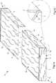
In
Den verschiedenen Varianten des in den
So wird bei dem erfindungsgemäßen Verfahren zunächst ein sich in eine Längsrichtung L erstreckendes Kantenband
Das Kantenband
Die Struktur
Ob das Kantenband
Wie im Folgenden anhand der Ausführungsbeispiele in den
Wie bereits angedeutet, kann das Kantenband
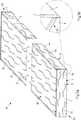
Im Folgenden wird unter Bezugnahme auf die
In den
Die nachgeschaltete Prägewalze
Auch die dreidimensionale Struktur
Für ein besonders gutes Ergebnis kann auch vorgesehen sein, dass die Struktur
Bei dem Verfahren in
Um das Prägeergebnis zu optimieren, sind verschiedene weitere Maßnahmen denkbar. So ist die die Struktur
Dem Kalander
Damit erfindungsgemäß die die Struktur
Zum einen kann vorgesehen sein, dass der Umfang des jeweiligen Druckzylinders
Zum anderen kann, wie
Die Markierungen
Die jeweilige Markierung
Die Steuerungseinrichtung
Wie gesagt kann alternativ oder zusätzlich aufgrund des Vergleichsergebnisses bei Überschreiten eines Sollwerts für den Versatz auch die Vorschubgeschwindigkeit des Kantenbands
In den
Die Oberseite
Die Schmalflächen
Dabei sind Dekor
Bei dem Ausführungsbeispiel eines Möbelteils
Das weitere Ausführungsbeispiel eines Möbelteils
ZITATE ENTHALTEN IN DER BESCHREIBUNG QUOTES INCLUDE IN THE DESCRIPTION
Diese Liste der vom Anmelder aufgeführten Dokumente wurde automatisiert erzeugt und ist ausschließlich zur besseren Information des Lesers aufgenommen. Die Liste ist nicht Bestandteil der deutschen Patent- bzw. Gebrauchsmusteranmeldung. Das DPMA übernimmt keinerlei Haftung für etwaige Fehler oder Auslassungen.This list of the documents listed by the applicant has been generated automatically and is included solely for the better information of the reader. The list is not part of the German patent or utility model application. The DPMA assumes no liability for any errors or omissions.
Zitierte PatentliteraturCited patent literature
- EP 2700511 A1[0004]EP 2700511 A1[0004]
- EP 1645339 A1[0005]EP 1645339 A1[0005]
- DE 19823195 C2[0014]DE 19823195 C2[0014]
Claims (23)
Translated fromGermanPriority Applications (6)
| Application Number | Priority Date | Filing Date | Title |
|---|---|---|---|
| DE102016109361.0ADE102016109361A1 (en) | 2016-05-20 | 2016-05-20 | Method for producing an edge profile and furniture part |
| CA3024567ACA3024567A1 (en) | 2016-05-20 | 2017-05-11 | Method for producing an edge profile and furniture component |
| US16/302,802US20190217601A1 (en) | 2016-05-20 | 2017-05-11 | Method for Producing an Edge Profile and Furniture Component |
| PCT/EP2017/061367WO2017198550A1 (en) | 2016-05-20 | 2017-05-11 | Method for producing an edge profile and furniture part |
| EP17723357.4AEP3458279A1 (en) | 2016-05-20 | 2017-05-11 | Method for producing an edge profile and furniture part |
| RU2018143204ARU2716191C1 (en) | 2016-05-20 | 2017-05-11 | Method of making edge profile and furniture element |
Applications Claiming Priority (1)
| Application Number | Priority Date | Filing Date | Title |
|---|---|---|---|
| DE102016109361.0ADE102016109361A1 (en) | 2016-05-20 | 2016-05-20 | Method for producing an edge profile and furniture part |
Publications (1)
| Publication Number | Publication Date |
|---|---|
| DE102016109361A1true DE102016109361A1 (en) | 2017-11-23 |
Family
ID=58707540
Family Applications (1)
| Application Number | Title | Priority Date | Filing Date |
|---|---|---|---|
| DE102016109361.0APendingDE102016109361A1 (en) | 2016-05-20 | 2016-05-20 | Method for producing an edge profile and furniture part |
Country Status (6)
| Country | Link |
|---|---|
| US (1) | US20190217601A1 (en) |
| EP (1) | EP3458279A1 (en) |
| CA (1) | CA3024567A1 (en) |
| DE (1) | DE102016109361A1 (en) |
| RU (1) | RU2716191C1 (en) |
| WO (1) | WO2017198550A1 (en) |
Cited By (2)
| Publication number | Priority date | Publication date | Assignee | Title |
|---|---|---|---|---|
| DE102017125744A1 (en)* | 2017-11-03 | 2019-05-09 | Falquon Gmbh | Method for producing a decorated surface of an article |
| EP4008554A1 (en)* | 2020-12-03 | 2022-06-08 | SWISS KRONO Tec AG | Method and device for processing an object |
Families Citing this family (4)
| Publication number | Priority date | Publication date | Assignee | Title |
|---|---|---|---|---|
| DE102019127325A1 (en)* | 2019-10-10 | 2021-04-15 | Leonhard Kurz Stiftung & Co. Kg | Coating device for coating a base body and a method |
| LU101796B1 (en)* | 2020-05-14 | 2021-11-15 | Phoenix Contact Gmbh & Co | Laser markable label |
| DE102022103652A1 (en)* | 2022-02-16 | 2023-08-17 | Van Der Vlis Design Gmbh | Three-dimensional structured decorative element |
| CN119278131A (en)* | 2022-05-31 | 2025-01-07 | 瓦林格创新股份有限公司 | Method for producing laminated substrate with embossed structure |
Citations (5)
| Publication number | Priority date | Publication date | Assignee | Title |
|---|---|---|---|---|
| EP0857442A2 (en)* | 1997-01-18 | 1998-08-12 | W. Döllken & Co GmbH | Method of making a profiled strip, in particular for an edge profile for the furniture industry |
| DE19823195C2 (en) | 1998-05-23 | 2003-03-20 | Doellken & Co Gmbh W | Method and device for printing on plastic workpiece surfaces |
| EP1645339A1 (en) | 2004-10-05 | 2006-04-12 | Fritz Egger GmbH & Co | Process and apparatus for making a structured surface and manufactured object with stuctured surface |
| EP2700511A1 (en) | 2012-08-21 | 2014-02-26 | Fritz Egger GmbH & Co. OG | Process for producing boards coated with decorative paper on both sides and method for producing such boards |
| EP2902216A1 (en)* | 2014-02-03 | 2015-08-05 | Kronotec AG | Functional unit |
Family Cites Families (7)
| Publication number | Priority date | Publication date | Assignee | Title |
|---|---|---|---|---|
| JP2000071691A (en)* | 1998-08-31 | 2000-03-07 | Dainippon Printing Co Ltd | Method of manufacturing wood decorative material |
| DE20315676U1 (en)* | 2003-10-11 | 2003-12-11 | Kronotec Ag | Panel, especially floor panel |
| SE526727C2 (en)* | 2003-11-13 | 2005-11-01 | Pergo Europ Ab | Process for making a decorative laminate with matched surface structure |
| US20070160807A1 (en)* | 2004-08-24 | 2007-07-12 | Mark Kraus | Grain-through flexible edgeband |
| US8474209B2 (en)* | 2008-01-11 | 2013-07-02 | Faus Group, Inc. | Precision surface technology |
| BE1018680A5 (en)* | 2008-12-19 | 2011-06-07 | Flooring Ind Ltd Sarl | METHODS FOR MANUFACTURING PANELS AND PANEL OBTAINED HEREBY |
| CA2684769A1 (en)* | 2009-11-06 | 2011-05-06 | Global Wood Concepts Ltd. | Edgebanding tape |
- 2016
- 2016-05-20DEDE102016109361.0Apatent/DE102016109361A1/enactivePending
- 2017
- 2017-05-11CACA3024567Apatent/CA3024567A1/enactivePending
- 2017-05-11RURU2018143204Apatent/RU2716191C1/enactive
- 2017-05-11EPEP17723357.4Apatent/EP3458279A1/enactivePending
- 2017-05-11WOPCT/EP2017/061367patent/WO2017198550A1/ennot_activeCeased
- 2017-05-11USUS16/302,802patent/US20190217601A1/ennot_activeAbandoned
Patent Citations (5)
| Publication number | Priority date | Publication date | Assignee | Title |
|---|---|---|---|---|
| EP0857442A2 (en)* | 1997-01-18 | 1998-08-12 | W. Döllken & Co GmbH | Method of making a profiled strip, in particular for an edge profile for the furniture industry |
| DE19823195C2 (en) | 1998-05-23 | 2003-03-20 | Doellken & Co Gmbh W | Method and device for printing on plastic workpiece surfaces |
| EP1645339A1 (en) | 2004-10-05 | 2006-04-12 | Fritz Egger GmbH & Co | Process and apparatus for making a structured surface and manufactured object with stuctured surface |
| EP2700511A1 (en) | 2012-08-21 | 2014-02-26 | Fritz Egger GmbH & Co. OG | Process for producing boards coated with decorative paper on both sides and method for producing such boards |
| EP2902216A1 (en)* | 2014-02-03 | 2015-08-05 | Kronotec AG | Functional unit |
Cited By (4)
| Publication number | Priority date | Publication date | Assignee | Title |
|---|---|---|---|---|
| DE102017125744A1 (en)* | 2017-11-03 | 2019-05-09 | Falquon Gmbh | Method for producing a decorated surface of an article |
| EP4008554A1 (en)* | 2020-12-03 | 2022-06-08 | SWISS KRONO Tec AG | Method and device for processing an object |
| WO2022117657A1 (en)* | 2020-12-03 | 2022-06-09 | SWISS KRONO Tec AG | Method and device for processing an object |
| US12397541B2 (en) | 2020-12-03 | 2025-08-26 | SWISS KRONO Tec AG | Method and device for processing an object |
Also Published As
| Publication number | Publication date |
|---|---|
| RU2716191C1 (en) | 2020-03-06 |
| CA3024567A1 (en) | 2017-11-23 |
| US20190217601A1 (en) | 2019-07-18 |
| EP3458279A1 (en) | 2019-03-27 |
| WO2017198550A1 (en) | 2017-11-23 |
Similar Documents
| Publication | Publication Date | Title |
|---|---|---|
| EP3458279A1 (en) | Method for producing an edge profile and furniture part | |
| DE60015603T2 (en) | METHOD FOR PRODUCING SURFACE ELEMENTS | |
| EP2516176B1 (en) | Method for producing a group of panels for imitating a slat | |
| EP2452829B1 (en) | Method for attaching a finish to a wooden material board | |
| EP1862304B1 (en) | Method for creating surface decoration on a panel and printing press for performing the process | |
| EP1973752B1 (en) | Wall panels, ceiling panels or floor panels | |
| EP2402154A1 (en) | Method for manufacturing flat components and component part | |
| EP3458240B1 (en) | Apparatus and method for fitting an edge profile, and furniture part | |
| DE102015118055A1 (en) | Edge profile for a plate-shaped material and plate-shaped material | |
| EP1175168B1 (en) | Method for producing furniture bodies and furniture body | |
| EP3649892A1 (en) | Edge strip and method for the production thereof | |
| EP2700511A1 (en) | Process for producing boards coated with decorative paper on both sides and method for producing such boards | |
| EP3415317A1 (en) | Method and device for producing a decorative surface | |
| DE102015110268A1 (en) | Process for producing a structuring material and structuring material | |
| EP3433109B1 (en) | Method for producing a laminate | |
| AT521998B1 (en) | Process for printing elongated profile strips and profile strips | |
| DE102022213489B3 (en) | Creating a decorative surface | |
| DE102012207965A1 (en) | Plate with a viewing surface, useful for producing furniture, preferably front of kitchen furniture, comprises a decorative layer printed with a pattern, a transparent layer, in which a surface structure is embossed | |
| DE102006048092A1 (en) | Furniture plate decorating method, involves printing coated broadside and circular edges with sublimable dispersed dye for decoration, and fixing imprint in and/or at powder lacquer under pressing pressure and heat | |
| DE102022103652A1 (en) | Three-dimensional structured decorative element | |
| DE102023103019A1 (en) | Decorative unit | |
| DE202023107534U1 (en) | Device for mechanical matting of bevels on decorative panel edges as well as decorative panel with mechanically matted bevel | |
| EP4624189A1 (en) | Method and device for producing a laminate, in particular a laminate in a cpl press with a synchronous structure to form a decoration | |
| WO2022117655A1 (en) | Method and apparatus for printing a surface of a paper |
Legal Events
| Date | Code | Title | Description |
|---|---|---|---|
| R012 | Request for examination validly filed |