DE102016108387A1 - Frame for a printed product - Google Patents
Frame for a printed productDownload PDFInfo
- Publication number
- DE102016108387A1 DE102016108387A1DE102016108387.9ADE102016108387ADE102016108387A1DE 102016108387 A1DE102016108387 A1DE 102016108387A1DE 102016108387 ADE102016108387 ADE 102016108387ADE 102016108387 A1DE102016108387 A1DE 102016108387A1
- Authority
- DE
- Germany
- Prior art keywords
- frame
- printed product
- removable
- elements
- magnetic elements
- Prior art date
- Legal status (The legal status is an assumption and is not a legal conclusion. Google has not performed a legal analysis and makes no representation as to the accuracy of the status listed.)
- Ceased
Links
- 239000011521glassSubstances0.000description3
- 230000007246mechanismEffects0.000description2
- 125000006850spacer groupChemical group0.000description2
- BUHVIAUBTBOHAG-FOYDDCNASA-N(2r,3r,4s,5r)-2-[6-[[2-(3,5-dimethoxyphenyl)-2-(2-methylphenyl)ethyl]amino]purin-9-yl]-5-(hydroxymethyl)oxolane-3,4-diolChemical compoundCOC1=CC(OC)=CC(C(CNC=2C=3N=CN(C=3N=CN=2)[C@H]2[C@@H]([C@H](O)[C@@H](CO)O2)O)C=2C(=CC=CC=2)C)=C1BUHVIAUBTBOHAG-FOYDDCNASA-N0.000description1
- 238000011109contaminationMethods0.000description1
- 230000007423decreaseEffects0.000description1
- 230000001419dependent effectEffects0.000description1
- 239000000428dustSubstances0.000description1
- 230000000694effectsEffects0.000description1
- 230000000977initiatory effectEffects0.000description1
- 230000010287polarizationEffects0.000description1
- 230000001681protective effectEffects0.000description1
- 230000000717retained effectEffects0.000description1
- 239000000725suspensionSubstances0.000description1
Images


Classifications
- A—HUMAN NECESSITIES
- A47—FURNITURE; DOMESTIC ARTICLES OR APPLIANCES; COFFEE MILLS; SPICE MILLS; SUCTION CLEANERS IN GENERAL
- A47G—HOUSEHOLD OR TABLE EQUIPMENT
- A47G1/00—Mirrors; Picture frames or the like, e.g. provided with heating, lighting or ventilating means
- A47G1/06—Picture frames
- A—HUMAN NECESSITIES
- A47—FURNITURE; DOMESTIC ARTICLES OR APPLIANCES; COFFEE MILLS; SPICE MILLS; SUCTION CLEANERS IN GENERAL
- A47G—HOUSEHOLD OR TABLE EQUIPMENT
- A47G1/00—Mirrors; Picture frames or the like, e.g. provided with heating, lighting or ventilating means
- A47G1/06—Picture frames
- A47G2001/0672—Picture frames employing magnets
Landscapes
- Mirrors, Picture Frames, Photograph Stands, And Related Fastening Devices (AREA)
Abstract
Translated fromGermanDescription
Translated fromGermanGegenstand der Erfindung ist ein Rahmen für ein Druckerzeugnis. Dieser Rahmen soll derart ausgestaltet sein, dass er zur Aufnahme des Druckerzeugnisses, also insbesondere eines Fotoalbums, Fotobuchs, Kalenders oder dergleichen geeignet ist. Insbesondere ist der Rahmen als ein Wandrahmen ausgebildet, das heisst das Druckerzeugnis wird mittels des Rahmens an einer Wand befestigt und gehalten.The invention relates to a frame for a printed product. This frame should be designed such that it is suitable for receiving the printed product, that is to say in particular a photo album, photo book, calendar or the like. In particular, the frame is designed as a wall frame, that is to say the printed product is fastened and held by means of the frame on a wall.
Herkömmliche Bilderrahmen, wie beispielsweise in der
In der
Allerdings eignet sich ein derartiger Bilderrahmen nicht für die Aufnahme eines Druckerzeugnisses, das heisst, eines Plattenelements, welches eine Dicke von mehr als 2 mm aufweist und ein Eigengewicht von mehr als 100 g aufweist. Ein derartiges Druckerzeugnis enthält insbesondere eine Mehrzahl von Blättern.However, such a picture frame is not suitable for receiving a printed product, that is, a plate member having a thickness of more than 2 mm and having a weight of more than 100 g. Such a printed product contains in particular a plurality of sheets.
Durch eine geringfügige Auslenkung der Magnete wird die Haltekraft derart verringert, dass ein Buch oder anderes Druckerzeugnis durch sein Eigengewicht die Rahmenecke verschieben kann. Durch eine Verschiebung der Position der Magneten kann die Rahmenecke öffnen und das Buch aus dem Rahmen fallen. Hierdurch kann eine Beschädigung des Rahmens und/oder des Buchs resultieren, insbesondere wenn der Bilderrahmen für eine Befestigung an einer Wand vorgesehen ist.By a slight deflection of the magnets, the holding force is reduced so that a book or other printed matter can move the frame corner by its own weight. By shifting the position of the magnets, the frame corner can open and the book fall out of the frame. This can result in damage to the frame and / or the book, especially if the picture frame is intended for attachment to a wall.
Daher wurden auch Rahmen speziell zur Aufnahme von Büchern konzipiert, wie beispielsweise in der
Somit besteht ein Bedarf nach einem Rahmen zur Aufnahme eines Druckerzeugnisses, der die Nachteile des Standes der Technik vermeidet.Thus, there is a need for a frame for receiving a printed product which avoids the disadvantages of the prior art.
Die
Die
Allerdings zeigt keine dieser Lösungen ein einfach abnehmbares Rahmenelement, mittels welchem das Druckereierzeugnis ohne Hilfsmittel entnommen und wieder aufnehmbar ist.However, none of these solutions shows a simply removable frame element by means of which the printed product is removed without aids and can be taken up again.
Aufgabe der Erfindung ist es daher, einen Rahmen bereitzustellen, in welchem ein Druckereierzeugnis innerhalb einer Mehrzahl von Rahmenelementen aufnehmbar und haltbar ist, wobei das Druckereierzeugnis ohne Hilfsmittel aus dem Rahmen entnehmbar ist, sodass eine andere Seite des Druckereierzeugnisses präsentiert werden kann.The object of the invention is therefore to provide a framework in which a printed product within a plurality of frame members is receivable and durable, the printed matter without tools is removed from the frame, so that another side of the printed matter can be presented.
Die Lösung dieser Aufgabe erfolgt durch den Gegenstand von Anspruch 1. Vorteilhafte Ausführungsbeispiele ergeben sich durch den Gegenstand der abhängigen Ansprüche 2–10.The solution of this object is achieved by the subject matter of
Der erfindungsgemässe Rahmen umfasst ein erstes Rahmenelement sowie ein zweites Rahmenelement. Das erste Rahmenelement kann aus einer Mehrzahl von Teilrahmenelementen bestehen. Zumindest eines der Rahmenelemente kann als abnehmbares Rahmenelement ausgebildet sein. Jedes der Teilrahmenelemente kann ebenfalls abnehmbar sein. Das abnehmbare Rahmenelement ist insbesondere das zweite Rahmenelement. Das abnehmbare Rahmenelement weist ein erstes Ende und ein zweites Ende auf, sowie eine an das Druckerzeugnis angrenzende Innenkante und eine Aussenkante. Das erste und das zweite Ende bilden je eine Seitenkante aus. Die Innenkante und die Aussenkante erstrecken sich vom ersten Ende bis zum zweiten Ende. Je ein Magnetelement ist am ersten Ende und am zweiten Ende vorgesehen, sodass das Rahmenelement an den ersten und zweiten Enden mit dem angrenzenden Rahmenelement mittels der Magnetelemente verbindbar ist. Somit kann das abnehmbare Rahmenelement von den Magnetelementen im ersten Rahmenelement gehalten werden. Zumindest eines der Rahmenelemente weist auf der an das Druckerzeugnis angrenzenden Kante eine Ausnehmung zur Aufnahme des zu präsentierenden Druckerzeugnisses auf. Die Magnetelemente sind als stabförmige Magnetelemente ausgebildet.The inventive frame comprises a first frame member and a second frame member. The first frame element may consist of a plurality of subframe elements. At least one of the frame members may be formed as a removable frame member. Each of the subframe elements may also be removable. The removable frame element is in particular the second frame element. The removable frame member has a first end and a second end, and an inner edge adjacent to the printed product and an outer edge. The first and the second end each form a side edge. The inner edge and the outer edge extend from the first end to the second end. Depending on a magnetic element is provided at the first end and the second end, so that the frame member is connectable at the first and second ends to the adjacent frame member by means of the magnetic elements. Thus, the detachable frame member can be held by the magnetic members in the first frame member. At least one of the frame elements has a recess for receiving the printed product to be presented on the edge adjacent to the printed product. The magnetic elements are designed as rod-shaped magnetic elements.
Vorteilhafterweise weisen die stabförmigen Magnetelemente eine Tragkraft von mindestens je 1 kg auf. Hierdurch können Druckerzeugnisse, wie insbesondere Kalender, kleinere Fotoalben, Bildbände oder dergleichen in diesem Rahmen gehalten werden. Für grössere Rahmen und/oder schwerere Objekte, die beispielsweise auch Flachbildschirme oder Tablets umfassen können, kann durch das abnehmbare Rahmenelement insbesondere eine Tragkraft von mindestens je 5 kg aufgenommen werden, insbesondere wenn das abnehmbare Rahmenelement bei vertikaler Ausrichtung an der Unterseite des Rahmens angeordnet ist.Advantageously, the rod-shaped magnetic elements have a carrying capacity of at least 1 kg each. As a result, printed products, in particular calendars, smaller photo albums, illustrated books or the like can be kept within this framework. For larger frames and / or heavier objects, which may include, for example, flat screens or tablets, can be absorbed by the removable frame member in particular a carrying capacity of at least 5 kg, especially if the removable frame member is arranged at vertical orientation on the underside of the frame.
Das abnehmbare Rahmenelement ist durch eine Auslenkung um einen Winkel von mindestens 5 Grad aus seiner Ruhelage vom Rahmen entfernbar. Die Auslenkung ist durch eine Drehung des Rahmenelements um seine Längsachse erzeugbar. Die Auslenkung kann um einen kleinen Winkel, der zwischen 5 und 15 Grad liegt, erfolgen. Insbesondere kann die Auslenkung um eine Längsachse des abnehmbaren Rahmenelements erfolgen.The removable frame member is removable by a deflection by an angle of at least 5 degrees from its rest position from the frame. The deflection can be generated by a rotation of the frame member about its longitudinal axis. The deflection can be done by a small angle, which is between 5 and 15 degrees. In particular, the deflection can take place about a longitudinal axis of the removable frame element.
Das stabförmige Magnetelement kann nach einem Ausführungsbeispiel einen rechteckigen Querschnitt aufweisen. Die Längsseite kann eine Länge von mindestens 10 mm und die Breitseite eine Breite von mindestens 2 mm aufweisen. Eine Mehrzahl von stabförmigen Magnetelementen kann vorgesehen sein. Die stabförmigen Magnetelemente können in Bezug auf die Dicke des abnehmbaren Rahmenelements nebeneinander angeordnet sein. Sie können auch hintereinander angeordnet sein, das heisst die stabförmigen Magnetelemente grenzen jeweils mit einer Breitseite aneinander.The rod-shaped magnetic element may have a rectangular cross-section according to an embodiment. The long side may have a length of at least 10 mm and the broad side a width of at least 2 mm. A plurality of rod-shaped magnetic elements may be provided. The rod-shaped magnetic members may be juxtaposed with respect to the thickness of the detachable frame member. They can also be arranged one behind the other, that is, the rod-shaped magnetic elements each adjoin one another with a broad side.
Insbesondere können die stabförmigen Magnetelemente von der Innenkante einen geringeren Abstand aufweisen als von der Aussenkante. Hierdurch kann die Hebelwirkung erhöht werden. Der Benutzer kann das abnehmbare Rahmenelement an seiner Aussenkante ergreifen oder die Aussenkante sowie die Innenkante umfassen und kann durch eine Winkeldrehung von 5 Grad bis maximal 15 Grad die stabförmigen Magnetelemente derart voneinander wegbewegen, dass die Haltekraft soweit vermindert ist, dass das abnehmbare Rahmenelement auf einfache Weise abgenommen werden kann. Der Benutzer kann auf eine Druckkraft auf die Aussenkante ausüben, um eine Kippbewegung einzuleiten, die dazu führt, dass die Magnetelemente des ersten Rahmenelements und des zweiten Rahmenelements nicht mehr übereinander liegen, wodurch die magnetische Anziehungskraft soweit vermindert wird, dass eine einfache Entnahme des Rahmenelements erfolgen kann. Die Kippbewegung oder Schwenkbewegung erfolgt somit um eine Längsachse des Rahmenelements, welche zwischen der Innenkante und der Aussenkante verläuft. Wenn die Innenkante parallel zur Aussenkante angeordnet ist, ist auch die Längsachse parallel zu der Innen- oder Aussenkante. Vorteilhafterweise ist die Längsachse näher der Innenkante als der Aussenkante gelegen. Dies hat zur Folge, das der Hebelarm von der Längsachse zur Aussenkante grösser ist, als der Hebelarm von der Längsachse zur Innenkante, sodass für die Ausführung der Schwenk- oder Kippbewegung ein geringerer Kraftaufwand erforderlich ist, wenn der Benutzer im Bereich der Aussenkante eine Druckkraft ausübt. Die Magnetelemente können sich auch bis über die gesamte Länge der Enden erstrecken, insbesondere wenn die Länge der Magnetelemente grösser als ihre Breite ist. Insbesondere ist es vorteilhaft, wenn die Länge des Magnetelements mindestens dreimal so gross wie dessen Breite ist. Werden zwei derartige lange, schmale gegenüberliegende Magnetelemente gegeneinander ausgelenkt, nimmt die Anziehungskraft selbst bei einer geringen Auslenkung von 5 bis 15 Grad schnell ab, sodass das Rahmenelement ohne grossen Kraftaufwand abgenommen werden kann, selbst wenn eine Mehrzahl von Magnetelementen hintereinander angeordnet sein muss, um eine höhere Tragkraft des Rahmens zu gewährleisten.In particular, the rod-shaped magnetic elements may have a smaller distance from the inner edge than from the outer edge. As a result, the leverage can be increased. The user can grasp the removable frame member at its outer edge or include the outer edge and the inner edge and can by an angular rotation of 5 degrees to a maximum of 15 degrees, the rod-shaped magnetic elements move away from each other so that the holding force is reduced so far that the removable frame element in a simple manner can be removed. The user can exert a compressive force on the outer edge to initiate a tilting movement, which causes the magnetic elements of the first frame member and the second frame member are no longer one above the other, whereby the magnetic attraction force is reduced so far that a simple removal of the frame member can. The tilting movement or pivoting movement thus takes place about a longitudinal axis of the frame element which extends between the inner edge and the outer edge. If the inner edge is arranged parallel to the outer edge, and the longitudinal axis is parallel to the inner or outer edge. Advantageously, the longitudinal axis is located closer to the inner edge than the outer edge. This has the consequence that the lever arm from the longitudinal axis to the outer edge is greater than the lever arm from the longitudinal axis to the inner edge, so that a lesser effort is required for the execution of the pivoting or tilting movement when the user exerts a compressive force in the region of the outer edge , The magnetic elements can also extend over the entire length of the ends, in particular if the length of the magnetic elements is greater than their width. In particular, it is advantageous if the length of the magnetic element is at least three times as large as its width. If two such long, narrow opposing magnetic elements deflected against each other, the attraction decreases rapidly even with a small deflection of 5 to 15 degrees, so that the frame member can be removed without much effort, even if a plurality of magnetic elements must be arranged one behind the other, a To ensure higher load capacity of the frame.
Nach dem vorliegenden Ausführungsbeispiel ist das abnehmbare Rahmenelement von der Unterseite des Rahmens ausgebildet, wenn der Rahmen sich in einer im Wesentlichen vertikalen Position befindet. Insbesondere kann der Rahmen an einer Wand befestigt sein. Wenn das abnehmbare Rahmenelement in dieser Position entfernt wird, kann das Druckerzeugnis durch sein Eigengewicht aus dem Rahmen entnommen werden. Es ist allerdings bei Öffnung des abnehmbaren Rahmenelements darauf zu achten, dass das Druckerzeugnis nicht unerwartet zu Boden fällt. Daher ist das abnehmbare Rahmenelement so konzipiert, dass es einhändig geöffnet werden kann. Insbesondere durch die Einleitung einer Drehbewegung durch Ausführung einer Kipp- oder Schwenkbewegung durch Druck auf die Aussenkante oder den an die Aussenkante angrenzenden Flächenbereich kann das Rahmenelement mit einer Hand entfernt werden und abgelegt werden, wobei mit der anderen Hand das Druckerzeugnis sicher gehalten werden kann bzw. gleichzeitig entnommen werden kann.According to the present embodiment, the detachable frame member is formed from the underside of the frame when the frame is in a substantially vertical position. In particular, the frame may be attached to a wall. When the detachable frame member is removed in this position, the printed matter can be removed from the frame by its own weight. However, when opening the removable frame element, make sure that the printed product does not fall unexpectedly to the floor. Therefore, the removable frame element is designed so that it can be opened with one hand. In particular, by initiating a rotary movement by executing a tilting or pivotal movement by pressure on the outer edge or adjacent to the outer edge surface area, the frame member can be removed and stored with one hand, with the other hand, the printed product can be held securely or can be removed simultaneously.
Der Rahmen kann eine Rückwand aufweisen. In der vertikalen Gebrauchsposition befindet sich die Rückwand zwischen dem Druckerzeugnis und der Wand, an welcher der Rahmen befestigt ist. Die Rückwand dient hauptsächlich dazu, den Raum, welcher das Druckerzeugnis aufnimmt, vor Verschmutzung zu bewahren. Die Rückwand kann auch eine dekorative Oberfläche aufweisen oder ein Bild oder Foto enthalten, das sichtbar wird, wenn kein Druckerzeugnis in dem Rahmen gehalten ist.The frame may have a back wall. In the vertical position of use is the back wall between the printed product and the wall to which the frame is attached. The back wall is mainly used to preserve the space that receives the printed matter, from contamination. The back wall may also have a decorative surface or contain an image or photograph that will become visible when no printed matter is held in the frame.
Insbesondere kann die Rückwand oder zumindest eines der Rahmenelemente ein Federelement umfassen, sodass Druckerzeugnisse mit variablen Dickenabmessungen in dem Rahmen aufnehmbar sind. Mit einem derartigen Federelement können Unterschiede in der Dicke der auszustellenden Druckerzeugnisse ausgeglichen werden.In particular, the rear wall or at least one of the frame elements may comprise a spring element, so that printed products with variable thickness dimensions can be accommodated in the frame. With such a spring element differences in the thickness of the printed products to be issued can be compensated.
Die Rückwand kann eine Ausnehmung zur Entnahme des Druckerzeugnisses enthalten. Insbesondere, wenn sich das abnehmbare Rahmenelement nicht an der Unterseite des Rahmens befindet, sondern an einer Seite oder der Oberseite des Rahmens, fällt das Druckerzeugnis nicht durch sein Eigengewicht aus dem Rahmen, sondern wird durch sein Eigengewicht im Rahmen zurückgehalten. Der Benutzer kann nach Abnahme des abnehmbaren Rahmenelements das Druckerzeugnis in der Ausnehmung halten und aus der Ausnehmung herausziehen. Durch die Ausnehmung kann die Lage des abnehmbaren Rahmenelements beliebig sein und das Druckerzeugnis kann auch aus einer beliebigen Lage des Rahmens entnommen werden. Insbesondere muss der Rahmen nicht von seiner Aufhängung an der Wand entfernt werden.The rear wall may include a recess for removing the printed product. In particular, if the removable frame member is not on the underside of the frame, but on one side or the top of the frame, the printed product does not fall from the frame by its own weight, but is retained by its own weight in the frame. The user can hold the printed product in the recess after removal of the removable frame member and pull out of the recess. Through the recess, the position of the removable frame member may be arbitrary and the printed product can also be removed from any position of the frame. In particular, the frame does not have to be removed from its suspension on the wall.
Nach einem Ausführungsbeispiel kann auf die Rückwand auch verzichtet werden, beispielsweise, wenn das Druckerzeugnis selbst mit einem Schutzumschlag ausgestattet ist.According to one embodiment, can also be dispensed with the back wall, for example, if the printed product itself is equipped with a dust jacket.
Insbesondere kann eines der Rahmenelemente aus drei Rahmenteilelementen aufgebaut sein. Die Rahmenteilelemente können fest miteinander verbunden sein, beispielsweise miteinander verklebt oder verleimt sein, sie können aber auch lösbar miteinander verbunden sein. Beispielsweise können an den Enden der Rahmenteilelemente ebenfalls Magnetelemente vorgesehen sein.In particular, one of the frame elements can be constructed from three frame sub-elements. The frame part elements may be firmly connected to each other, for example glued or glued together, but they can also be releasably connected to each other. For example, magnetic elements may also be provided at the ends of the frame part elements.
Insbesondere kann die Ausnehmung an der Innenseite zumindest eines der Rahmenelemente L-förmig ausgebildet sein, sodass mit der Rückwand ein u-förmiger Kanal ausgebildet wird. Die Ausnehmung kann insbesondere umlaufend ausgebildet sein. Insbesondere kann die Ausnehmung auch als Nut ausgeführt sein.In particular, the recess on the inside of at least one of the frame elements may be L-shaped, so that a U-shaped channel is formed with the rear wall. The recess may in particular be formed circumferentially. In particular, the recess may also be designed as a groove.
Das Druckerzeugnis kann insbesondere durch eine transparente Abdeckungsplatte vor Nässe oder Schmutz geschützt werden. Die Abdeckungsplatte kann beispielsweise eine Glas- oder Kunststoffplatte umfassen. Das Druckerzeugnis ist zwischen der Rückwand der transparenten Abdeckungsplatte sowie den Rahmenelementen haltbar.The printed product can be protected in particular by a transparent cover plate from moisture or dirt. The cover plate may for example comprise a glass or plastic plate. The printed matter is durable between the rear wall of the transparent cover plate and the frame members.
Nach einem Ausführungsbeispiel können das abnehmbare Rahmenelement sowie die Rahmenteilelemente aus Modulen aufgebaut sein, beispielsweise zusammengesteckt sein und/oder ebenfalls mit Magnetelementen miteinander verbunden sein. Durch die Verwendung von Modulen kann bei Bedarf die Rahmengrösse an Druckerzeugnisse mit unterschiedlichen Längenabmessungen sowie Breitenabmessungen angepasst werden, indem einzelne Module aus den Rahmenelementen entfernt werden oder zusätzliche Module angebracht werden. Vorzugsweise haben sämtliche Module dieselben Abmessungen, sodass sie für ein beliebiges Rahmenelement bausteinartig einsetzbar sind.According to one embodiment, the removable frame member and the frame part elements may be constructed of modules, for example, be plugged together and / or also be connected to each other with magnetic elements. By using modules, if necessary, the frame size can be adapted to print products with different length dimensions and width dimensions by removing individual modules from the frame elements or by attaching additional modules. Preferably, all modules have the same dimensions, so that they can be used in blocks for any frame element.
Nachfolgend wird der erfindungsgemässe Rahmen anhand einiger Ausführungsbeispiele dargestellt. Es zeigen:The frame according to the invention will now be described with reference to some embodiments. Show it:
Vorteilhafterweise weisen die stabförmigen Magnetelemente
Das abnehmbare Rahmenelement
Das stabförmige Magnetelement
Nach dem vorliegenden Ausführungsbeispiel ist das abnehmbare Rahmenelement
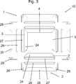
Gemäss des vorliegenden Ausführungsbeispiels ist das erste Rahmenelement
Insbesondere kann die Ausnehmung
Das Druckerzeugnis kann insbesondere durch eine transparente Abdeckungsplatte vor Nässe oder Schmutz geschützt werden. Die Abdeckungsplatte kann beispielsweise eine Glas- oder Kunststoffplatte umfassen. Das Druckerzeugnis ist zwischen der Rückwand
Der Rahmen
Ein weiterer Schnitt ist durch das Rahmenteilelement
Die Rückwand
Das Rahmenelement
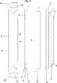
In
Das Rahmenteilelement
Die Innenansicht
In
Das abnehmbare Rahmenelement
Für die Innenansicht
Jedes der dargestellten Ausführungsbeispiele kann mit Halterungen ausgestattet sein, welche eine Befestigung des Rahmens an der Wand ermöglichen. Eine Rückwand könnte weggelassen werden, wenn die Rahmenelemente einen u-förmigen Kanal aufweisen, in welchen das Druckerzeugnis eingesteckt wird. Das Druckerzeugnis wird nach dieser Variante nur in den Rahmenelementen gehalten. Jedes der Rahmenelemente oder die Rückwand könnten Spannmechanismen enthalten, sodass auch Bücher unterschiedlicher Dicke im Rahmen gehalten werden können. Derartige Spannmechanismen sind beispielsweise in den Dokumenten
ZITATE ENTHALTEN IN DER BESCHREIBUNG QUOTES INCLUDE IN THE DESCRIPTION
Diese Liste der vom Anmelder aufgeführten Dokumente wurde automatisiert erzeugt und ist ausschließlich zur besseren Information des Lesers aufgenommen. Die Liste ist nicht Bestandteil der deutschen Patent- bzw. Gebrauchsmusteranmeldung. Das DPMA übernimmt keinerlei Haftung für etwaige Fehler oder Auslassungen.This list of the documents listed by the applicant has been generated automatically and is included solely for the better information of the reader. The list is not part of the German patent or utility model application. The DPMA assumes no liability for any errors or omissions.
Zitierte PatentliteraturCited patent literature
- US 20100083548 A1[0002, 0002, 0003]US 20100083548 A1[0002, 0002, 0003]
- US 2014259840 A1[0003]US 2014259840 A1[0003]
- GB 2451269 A[0006]GB 2451269 A[0006]
- GB 2451269[0008]GB 2451269[0008]
- US 6186465 B1[0009, 0055]US 6186465 B1[0009, 0055]
- US 2649799 A[0055]US 2649799A[0055]
Claims (10)
Translated fromGermanApplications Claiming Priority (2)
| Application Number | Priority Date | Filing Date | Title |
|---|---|---|---|
| CH00629/15ACH711086B1 (en) | 2015-05-07 | 2015-05-07 | Frame for a printed product. |
| CHCH00629/15 | 2015-05-07 |
Publications (1)
| Publication Number | Publication Date |
|---|---|
| DE102016108387A1true DE102016108387A1 (en) | 2016-11-10 |
Family
ID=57179093
Family Applications (1)
| Application Number | Title | Priority Date | Filing Date |
|---|---|---|---|
| DE102016108387.9ACeasedDE102016108387A1 (en) | 2015-05-07 | 2016-05-05 | Frame for a printed product |
Country Status (2)
| Country | Link |
|---|---|
| CH (1) | CH711086B1 (en) |
| DE (1) | DE102016108387A1 (en) |
Citations (5)
| Publication number | Priority date | Publication date | Assignee | Title |
|---|---|---|---|---|
| US2649799A (en) | 1950-08-19 | 1953-08-25 | Spertus Maurice | Picture-frame album |
| US6186465B1 (en) | 1998-08-27 | 2001-02-13 | Stephen Clark | Book display apparatus |
| GB2451269A (en) | 2007-07-25 | 2009-01-28 | Ricardo Pulido Garzon | Wall mountable display case for book |
| US20100083548A1 (en) | 2008-10-08 | 2010-04-08 | Reis Richard C | Configurable modular picture frame |
| US20140259840A1 (en) | 2013-03-15 | 2014-09-18 | Fujifilm North America Corporation | Multi-level picture frame |
- 2015
- 2015-05-07CHCH00629/15Apatent/CH711086B1/ennot_activeIP Right Cessation
- 2016
- 2016-05-05DEDE102016108387.9Apatent/DE102016108387A1/ennot_activeCeased
Patent Citations (5)
| Publication number | Priority date | Publication date | Assignee | Title |
|---|---|---|---|---|
| US2649799A (en) | 1950-08-19 | 1953-08-25 | Spertus Maurice | Picture-frame album |
| US6186465B1 (en) | 1998-08-27 | 2001-02-13 | Stephen Clark | Book display apparatus |
| GB2451269A (en) | 2007-07-25 | 2009-01-28 | Ricardo Pulido Garzon | Wall mountable display case for book |
| US20100083548A1 (en) | 2008-10-08 | 2010-04-08 | Reis Richard C | Configurable modular picture frame |
| US20140259840A1 (en) | 2013-03-15 | 2014-09-18 | Fujifilm North America Corporation | Multi-level picture frame |
Also Published As
| Publication number | Publication date |
|---|---|
| CH711086B1 (en) | 2018-11-15 |
| CH711086A2 (en) | 2016-11-15 |
Similar Documents
| Publication | Publication Date | Title |
|---|---|---|
| EP0105454A1 (en) | Holder for a stack of pictures | |
| DE69008470T2 (en) | Loose-leaf binder. | |
| DE102011014141A1 (en) | Closing device, which is connectable to the opening of the cooking chamber of a "trolley" type oven, for the sealed closure of the chamber without a trolley | |
| EP3714736A1 (en) | Mobile display part, whiteboard and method for holding a mobile display part | |
| DE102016108387A1 (en) | Frame for a printed product | |
| DE2122689C3 (en) | Strip board | |
| DE60004746T2 (en) | Paper container with attached side walls | |
| DE1934600A1 (en) | Coin holder | |
| DE202021100198U1 (en) | Hinged gift box | |
| DE102008019530A1 (en) | Holding device for being inserted into hinged storage space of passenger seat in e.g. aircraft, has transparent front side pressed and held against rear side by magnetic force in mounting condition | |
| DE212016000083U1 (en) | Fully demountable pocket filter with rigid filter panels | |
| AT521867A1 (en) | Color chart | |
| DE2637455A1 (en) | Changeable picture frame for wall - has triple element construction with folding flap section | |
| DE4110044A1 (en) | BACK PLATE HOLDER FOR LETTER FOLDER | |
| DE102006010575A1 (en) | Device for exchangeable holding of pages in form book has first and second holding and/or connecting element on inner side of front and rear cover side respectively, enabling pages to be added or exchanged | |
| DE20014306U1 (en) | Calendar, especially advent calendar | |
| DE1959890C3 (en) | Slide film protective cover | |
| DE212005000053U1 (en) | Adjustable material holding device | |
| DE2826039C2 (en) | ||
| DE1536481C3 (en) | Device for sticking several data sheets in specified fields of a carrier sheet | |
| AT404223B (en) | DEVICE FOR PRESENTING LARGE WRITTEN PAPERS | |
| DE538000C (en) | Film pack | |
| DE567540C (en) | Facility, e.g. B. folder or bag, for the orderly storage of documents and other flat objects | |
| DE102012107524A1 (en) | Flat presentation and/or holding device for presentation and/or holding object i.e. plant, has floor elements connected with each other over part of device, and fastening element and/or connection unit connected with each other | |
| DE2851509C3 (en) | Photo frames with multiple inner frames |
Legal Events
| Date | Code | Title | Description |
|---|---|---|---|
| R012 | Request for examination validly filed | ||
| R002 | Refusal decision in examination/registration proceedings | ||
| R003 | Refusal decision now final |