DE102016103426A1 - Refrigerant compressor and method for monitoring, controlling and / or controlling a refrigerant compressor - Google Patents
Refrigerant compressor and method for monitoring, controlling and / or controlling a refrigerant compressorDownload PDFInfo
- Publication number
- DE102016103426A1 DE102016103426A1DE102016103426.6ADE102016103426ADE102016103426A1DE 102016103426 A1DE102016103426 A1DE 102016103426A1DE 102016103426 ADE102016103426 ADE 102016103426ADE 102016103426 A1DE102016103426 A1DE 102016103426A1
- Authority
- DE
- Germany
- Prior art keywords
- refrigerant compressor
- system components
- compressor
- monitoring
- components
- Prior art date
- Legal status (The legal status is an assumption and is not a legal conclusion. Google has not performed a legal analysis and makes no representation as to the accuracy of the status listed.)
- Granted
Links
- 239000003507refrigerantSubstances0.000titleclaimsabstractdescription57
- 238000012544monitoring processMethods0.000titleclaimsdescription29
- 238000000034methodMethods0.000titleclaimsdescription9
- 230000001276controlling effectEffects0.000claimsdescription5
- 230000001105regulatory effectEffects0.000claimsdescription3
- 230000002457bidirectional effectEffects0.000claimsdescription2
- 238000005057refrigerationMethods0.000description6
- 238000001514detection methodMethods0.000description3
- 238000002347injectionMethods0.000description3
- 239000007924injectionSubstances0.000description3
- 239000007788liquidSubstances0.000description3
- 238000013021overheatingMethods0.000description3
- 238000004804windingMethods0.000description3
- 238000011109contaminationMethods0.000description2
- 238000001816coolingMethods0.000description2
- BUHVIAUBTBOHAG-FOYDDCNASA-N(2r,3r,4s,5r)-2-[6-[[2-(3,5-dimethoxyphenyl)-2-(2-methylphenyl)ethyl]amino]purin-9-yl]-5-(hydroxymethyl)oxolane-3,4-diolChemical compoundCOC1=CC(OC)=CC(C(CNC=2C=3N=CN(C=3N=CN=2)[C@H]2[C@@H]([C@H](O)[C@@H](CO)O2)O)C=2C(=CC=CC=2)C)=C1BUHVIAUBTBOHAG-FOYDDCNASA-N0.000description1
- 238000004891communicationMethods0.000description1
- 239000002826coolantSubstances0.000description1
- 238000004132cross linkingMethods0.000description1
- 230000007547defectEffects0.000description1
- 238000005461lubricationMethods0.000description1
- 230000007257malfunctionEffects0.000description1
- 238000012806monitoring deviceMethods0.000description1
- 230000002028prematureEffects0.000description1
- 230000001960triggered effectEffects0.000description1
Images

Classifications
- F—MECHANICAL ENGINEERING; LIGHTING; HEATING; WEAPONS; BLASTING
- F25—REFRIGERATION OR COOLING; COMBINED HEATING AND REFRIGERATION SYSTEMS; HEAT PUMP SYSTEMS; MANUFACTURE OR STORAGE OF ICE; LIQUEFACTION SOLIDIFICATION OF GASES
- F25B—REFRIGERATION MACHINES, PLANTS OR SYSTEMS; COMBINED HEATING AND REFRIGERATION SYSTEMS; HEAT PUMP SYSTEMS
- F25B49/00—Arrangement or mounting of control or safety devices
- F25B49/02—Arrangement or mounting of control or safety devices for compression type machines, plants or systems
- F—MECHANICAL ENGINEERING; LIGHTING; HEATING; WEAPONS; BLASTING
- F04—POSITIVE - DISPLACEMENT MACHINES FOR LIQUIDS; PUMPS FOR LIQUIDS OR ELASTIC FLUIDS
- F04B—POSITIVE-DISPLACEMENT MACHINES FOR LIQUIDS; PUMPS
- F04B35/00—Piston pumps specially adapted for elastic fluids and characterised by the driving means to their working members, or by combination with, or adaptation to, specific driving engines or motors, not otherwise provided for
- F04B35/04—Piston pumps specially adapted for elastic fluids and characterised by the driving means to their working members, or by combination with, or adaptation to, specific driving engines or motors, not otherwise provided for the means being electric
- F—MECHANICAL ENGINEERING; LIGHTING; HEATING; WEAPONS; BLASTING
- F04—POSITIVE - DISPLACEMENT MACHINES FOR LIQUIDS; PUMPS FOR LIQUIDS OR ELASTIC FLUIDS
- F04B—POSITIVE-DISPLACEMENT MACHINES FOR LIQUIDS; PUMPS
- F04B39/00—Component parts, details, or accessories, of pumps or pumping systems specially adapted for elastic fluids, not otherwise provided for in, or of interest apart from, groups F04B25/00 - F04B37/00
- F04B39/12—Casings; Cylinders; Cylinder heads; Fluid connections
- F04B39/121—Casings
Landscapes
- Engineering & Computer Science (AREA)
- Mechanical Engineering (AREA)
- General Engineering & Computer Science (AREA)
- Physics & Mathematics (AREA)
- Thermal Sciences (AREA)
- Control Of Positive-Displacement Pumps (AREA)
Abstract
Translated fromGermanDescription
Translated fromGermanDie Erfindung betrifft einen Kältemittelverdichter und ein Verfahren zur Überwachung, Regelung und/oder Steuerung eines Kältemittelverdichters.The invention relates to a refrigerant compressor and a method for monitoring, regulating and / or controlling a refrigerant compressor.
Aus der
Der Betriebszustand des Verdichters wird über wenigstens einen Parameter, beispielsweise über die Wicklungstemperatur oder die Heißgastemperatur, überwacht, wobei ein Über- oder Unterschreiten einer vorgegebenen Abschaltschwelle zum Abschalten des Verdichters führt. Die Auslösung des Verdichterschutzes bedeutet somit eine zwangsläufige Unterbrechung der Kälteerzeugung und kann daher erhebliche Folgen haben. Darüber hinaus ist ein Neustart mit der Verunsicherung über die Ursache der Auslösung verbunden. Manche Hersteller von Verdichtern lassen einen weiteren Betrieb des Verdichters in einem derartigen Fall erst dann zu, wenn die Ursache geklärt bzw. behoben ist. Bei einem bekannten Regelalgorithmus kann es daher aufgrund eines erhöhten Bedarfs, einer falsch ausgelegten Anlage, einer falschen Kältemittelmenge oder einer nicht ordnungsgemäßen Anwendung zu einen Auslösung des Verdichterschutzes kommen, ohne dass ein tatsächlicher Komponentendefekt oder eine Funktionsstörung im System vorliegt. Die
Der Erfindung liegt nun die Aufgabe zugrunde, die Verfügbarkeit und die Effizienz der Kälteerzeugung weiter zu optimieren.The invention is based on the object to further optimize the availability and efficiency of refrigeration.
Erfindungsgemäß wird diese Aufgabe durch die Merkmale der Ansprüche 1 und 13 gelöst. Vorteilhafte Ausgestaltungen der Erfindung sind Gegenstand der weiteren Ansprüche.According to the invention, this object is solved by the features of
Der erfindungsgemäße Kältemittelverdichter weist einen Elektromotor auf, der mit wenigstens zwei Systemkomponenten in Wirkverbindung steht. Die wenigstens zwei Systemkomponenten sind räumlich verteilt am oder im Kältemittelverdichter angebracht und sind mit jeweils eigener Elektronik ausgestattet, wobei die wenigstens zwei Systemkomponenten für einen Informationsaustausch über ein Bussystem miteinander verbunden sind.The refrigerant compressor according to the invention has an electric motor which is in operative connection with at least two system components. The at least two system components are spatially distributed on or in the refrigerant compressor and are each equipped with their own electronics, wherein the at least two system components are interconnected for information exchange via a bus system.
Beim erfindungsgemäßen Verfahren zur Überwachung, Regelung und/oder Steuerung eines Kältemittelverdichters mit einem Elektromotor kommen wenigstens zwei Systemkomponenten zum Einsatz, die mit eigener Elektronik funktionieren und räumlich verteilt am Kältemittelverdichter angeordnet sind, wobei Informationen zwischen den wenigstens zwei Systemkomponenten über ein Bussystem übertragen werden.In the method according to the invention for monitoring, regulating and / or controlling a refrigerant compressor with an electric motor, at least two system components are used, which operate with their own electronics and are arranged spatially distributed on the refrigerant compressor, wherein information is transmitted between the at least two system components via a bus system.
Die Systemkomponenten können insbesondere durch wenigstens zwei der nachfolgend aufgeführten Systemkomponenten gebildet werden: Überwachungssystem, Leistungssteller, Ölspiegelregulator oder weitere am Verdichter angebrachte Sensoren, Aktoren oder Steuerungen.The system components can be formed in particular by at least two of the system components listed below: monitoring system, power controller, oil level regulator or other sensors, actuators or controllers attached to the compressor.
Wenngleich Systemkomponenten, wie Überwachungssystem, Leistungssteller und Ölspiegelregulator bei bekannten Kältemittelverdichtern üblicherweise in Wirkverbindung stehen, findet jedoch bis jetzt noch keine direkte Kommunikation miteinander statt. Bisher sind diese Komponenten über eine „UND-Verknüpfung“ mit einem Schütz verbunden, sodass der Kältemittelverdichter über das Schütz abgeschaltet werden kann, sofern bei einer einzelnen Systemkomponente ein kritischer Zustand erreicht wird.Although system components such as monitoring system, power controller and oil level regulator are usually in operative connection with known refrigerant compressors, however, there is still no direct communication with each other. So far, these components are connected via an "AND link" with a contactor, so that the refrigerant compressor can be switched off via the contactor, if a critical condition is reached in a single system component.
Natürlich mag es andere Systemkomponenten in einer Kälteanlage geben, die beispielsweise in einem Schaltschrank untergebracht sind und über ein Bussystem miteinander verbunden sind, jedoch ist es bis jetzt noch nicht bekannt, zwei oder mehrere, am oder im Kältemittelverdichter angeordnete Systemkomponenten über ein Bussystem miteinander zu verbinden.Of course, there may be other system components in a refrigeration system that are housed for example in a control cabinet and connected to each other via a bus system, however, it is not yet known to connect two or more, arranged on or in the refrigerant compressor system components via a bus system ,
Durch den erfindungsgemäßen Informationsaustausch über das Bussystem sind beispielsweise folgende Szenarien denkbar, um die Effizienz und/oder Verfügbarkeit der Kälteerzeugung zu optimieren:
- – Wenn der Kältemittelverdichter läuft, kann ein Ölsumpfheizer ausgeschaltet werden, wodurch Energie eingespart wird.
- – Wenn die Umgebungstemperatur größer als ein bestimmter Wert ist, kann der Ölsumpfheizer ausgeschaltet werden, wodurch ebenfalls Energie eingespart wird.
- – Wenn der Saugdruck am Kältemittelverdichter zu niedrig ist, kann die Verdichterleistung reduziert werden, wodurch sich die Verfügbarkeit maximiert.
- – Die Flüssigkeitseinspritzung oder der Kopflüfter werden nur aktiviert, wenn das Überwachungssystem eine zu hohe Temperatur in der Motorwicklung oder beim Verdichten Heißgas melden, wodurch Energie gespart wird.
- - When the refrigerant compressor is running, an oil sump heater can be turned off, saving energy.
- - If the ambient temperature is greater than a certain value, the oil sump heater can be switched off, which also saves energy.
- - If the suction pressure at the refrigerant compressor is too low, the compressor capacity can be reduced, which maximizes the availability.
- - The liquid injection or the head fan will only be activated if the monitoring system reports too high a temperature in the motor winding or when compressing hot gas, which saves energy.
Die Erfindung schlägt somit eine Vernetzung der am oder im Kältemittelverdichter angebrachten Systemkomponenten vor, um die Betriebsweise einzelner oder mehrerer Systemkomponenten anzupassen.The invention thus proposes crosslinking the system components mounted on or in the refrigerant compressor in order to adapt the mode of operation of individual or several system components.
Unter einem Überwachungssystem wird eine Systemkomponente verstanden, die beispielsweise einen Sensor zur Überwachung eines Parameters des Kältemittelverdichters umfasst. Herbei kann es sich beispielsweise um einen Temperatur- oder Druckwert handeln. Der Ölspiegelregulator dient zur Überwachung und Einhaltung eines vorgegebenen Ölniveaus im Kältemittelverdichter. Der Leistungssteller dient beispielsweise zur Einstellung des Volumenstroms des Kältemittels oder zum Setzen der Ventile des Kältemittelverdichters in die richtige Position, um beispielsweise eine Entlastung beim Anlaufen zu bewirken. Ein Kopflüfter oder eine Steuerung zur Flüssigkeitseinspritzung dienen zur aktiven Kühlung des Verdichters, um ein Überhitzen und dadurch bedingtes Abschalten zu vermeiden.A monitoring system is understood to be a system component that includes, for example, a sensor for monitoring a parameter of the refrigerant compressor. For example, this can be a temperature or pressure value. The oil level regulator is used to monitor and maintain a given oil level in the refrigerant compressor. The power controller is used, for example, to adjust the volume flow of the refrigerant or to set the valves of the refrigerant compressor in the correct position, for example, to bring about relief during startup. A head fan or liquid injection control is used to actively cool the compressor to prevent overheating and consequent shutdown.
Gemäß einer bevorzugten Ausgestaltung der Erfindung wird eine der wenigstens zwei Systemkomponenten durch das Überwachungssystem gebildet, wobei dieses vorzugsweise wenigstens einen Sensor zur Überwachung eines Parameters des Kältemittelverdichters umfasst. Vorzugsweise sind aber sowohl das Überwachungssystem, der Leistungssteller, eine Steuerung von Kopflüfter oder Flüssigkeitseinspritzung und der Ölspiegelregulator vorhanden und über das Bussystem miteinander verbunden.According to a preferred embodiment of the invention, one of the at least two system components is formed by the monitoring system, which preferably comprises at least one sensor for monitoring a parameter of the refrigerant compressor. Preferably, however, both the monitoring system, the power controller, a controller of head fan or liquid injection and the oil level regulator are present and connected to each other via the bus system.
Gemäß einer weiteren Ausgestaltung der Erfindung weist der Kältemittelverdichter weiterhin ein mit wenigstens einer, vorzugsweise beiden, höchstvorzugsweise allen Systemkomponenten verbundenes Schütz zum Abschalten des Verdichtermotors auf. Die eine bzw. die mehreren Systemkomponenten sind dabei über eine vom Bussystem separate Leitung mit dem Schütz verbunden. Die Verbindung über diese separate Leitung ist dabei so aufgebaut, dass alle mit dem Schütz verbundenen Systemkomponenten in Reihe geschaltet sind und das Schütz dann zum Abschalten des Elektromotors deaktiviert wird, wenn diese separate Leitung durch eine der verbundenen Systemkomponenten unterbrochen wird („UND-Verknüpfung). Es reicht somit aus, wenn eine der Systemkomponenten einen Betriebszustand des Kältemittelverdichters feststellt, der ein Abschalten desselben erfordert.According to a further embodiment of the invention, the refrigerant compressor further comprises a contactor for switching off the compressor motor connected to at least one, preferably both, most preferably all system components. The one or more system components are connected via a separate line from the bus system to the contactor. The connection via this separate line is constructed in such a way that all system components connected to the contactor are connected in series and the contactor is then deactivated to switch off the electric motor if this separate line is interrupted by one of the connected system components ("AND operation"). , It is therefore sufficient if one of the system components detects an operating state of the refrigerant compressor, which requires a shutdown thereof.
Weiterhin kann vorgesehen werden, dass jede der wenigstens zwei Systemkomponenten als Stand-Alone-Komponente ausgebildet ist und somit die ihr zugewiesene Aufgabe auch unabhängig von den anderen Systemkomponenten ausüben kann. Durch das Bussystem, welches unidirektional oder bidirektional ausgebildet sein kann, werden den Systemkomponenten die Informationen anderer Systemkomponenten bereitgestellt, die dann von einem Prozessor dieser Systemkomponente verarbeitet und bei der Ausführung der Aufgabe dieser Systemkomponente berücksichtigt werden können.Furthermore, it can be provided that each of the at least two system components is designed as a stand-alone component and thus can also perform the assigned task independently of the other system components. The bus system, which may be unidirectional or bidirectional, provides the system components with the information of other system components, which can then be processed by a processor of this system component and taken into account in the execution of the task of this system component.
Weitere Vorteile und Ausgestaltungen der Erfindung werden im Folgenden anhand der nachfolgenden Beschreibung eines Ausführungsbeispiels und der Zeichnung näher erläutert.Further advantages and embodiments of the invention will be explained in more detail below with reference to the following description of an embodiment and the drawing.
In der Zeichnung zeigen:In the drawing show:
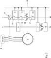
Der in
Im Bereich der Verdichtereinheit
Die Differenzdrucküberwachungseinheit
Der Ölspiegelregulator
Das im Klemmkasten
In
Des Weiteren sind ein Teil der Systemkomponenten, nämlich der Ölspiegelregulator
Im Folgenden werden verschiedene Szenarien erläutert, bei denen die über das Bussystem
Dient das Überwachungssystem
Stellt das Überwachungssystem beispielsweise einen erhöhten Motorwiderstand fest, kann der Leistungssteller eine Erhöhung des Volumenstroms des Kältemittels bewirken, um eine Überhitzung zu vermeiden. In ähnlicher Weise kann auch die Motortemperatur dazu genutzt werden.For example, if the monitoring system detects an increased motor resistance, the power controller may cause an increase in the volume flow of the refrigerant to prevent overheating. Similarly, the engine temperature can also be used.
Wenn das Überwachungssystem Aufgrund eines Defekts seines internen Relais nicht mehr abschalten kann (z.B. Kontakte verschweißt) erfolgt über den Bus die „Abschaltinformation“, so dass die anderen Komponenten ebenfalls die Sicherheitskette unterbrechen können und somit die Anlage dennoch abgeschaltet wird, bevor eine Beschädigung eintritt.If the monitoring system can not shut down due to a failure of its internal relay (e.g., contacts welded), the "shutdown information" will be sent through the bus so that the other components can also break the safety chain, thus shutting down the system before any damage occurs.
Misst das Überwachungsgerät beispielweise den Öldifferenzdruck, kann diese Information im Ölspiegelregulator als Plausibilitätskontrolle für eine Verschmutzung verwendet werden. Wird die Frequenz oder Drehzahl überwacht, kann dies beim Ölspiegelregulator im Falle einer hohen Frequenz zu einer vorsorglichen Nachspeisung von Öl führen. Wird mit dem Überwachungssystem die Temperatur des verdichteten Kühlmediums
Stellt der Ölspiegelregulator eine Information über die Anzahl der Ölnachfüllungen pro Stunde bereit, kann diese im Leistungssteller zur Optimierung der Leistungsregelung genutzt werden, um dadurch die Verfügbarkeit bei hohem Ölwurf zu gewährleisten.If the oil level regulator provides information on the number of oil refills per hour, it can be used in the power controller to optimize the power control, thereby ensuring high oil throw availability.
Die obige Aufstellung von verschiedenen Szenarien ist lediglich beispielhaft und keineswegs abschließend. Je nach Ausgestaltung des Überwachungssystems und des Leistungsstellers sind andere Anwendungsbeispiele denkbar.The above listing of different scenarios is merely exemplary and by no means exhaustive. Depending on the configuration of the monitoring system and the power controller other application examples are conceivable.
ZITATE ENTHALTEN IN DER BESCHREIBUNG QUOTES INCLUDE IN THE DESCRIPTION
Diese Liste der vom Anmelder aufgeführten Dokumente wurde automatisiert erzeugt und ist ausschließlich zur besseren Information des Lesers aufgenommen. Die Liste ist nicht Bestandteil der deutschen Patent- bzw. Gebrauchsmusteranmeldung. Das DPMA übernimmt keinerlei Haftung für etwaige Fehler oder Auslassungen.This list of the documents listed by the applicant has been generated automatically and is included solely for the better information of the reader. The list is not part of the German patent or utility model application. The DPMA assumes no liability for any errors or omissions.
Zitierte PatentliteraturCited patent literature
- DE 102005052042 A1[0002, 0003]DE 102005052042 A1[0002, 0003]
Claims (14)
Translated fromGermanPriority Applications (1)
| Application Number | Priority Date | Filing Date | Title |
|---|---|---|---|
| DE102016103426.6ADE102016103426B4 (en) | 2016-02-26 | 2016-02-26 | Refrigerant compressor and method for monitoring, regulating and / or controlling a refrigerant compressor |
Applications Claiming Priority (1)
| Application Number | Priority Date | Filing Date | Title |
|---|---|---|---|
| DE102016103426.6ADE102016103426B4 (en) | 2016-02-26 | 2016-02-26 | Refrigerant compressor and method for monitoring, regulating and / or controlling a refrigerant compressor |
Publications (2)
| Publication Number | Publication Date |
|---|---|
| DE102016103426A1true DE102016103426A1 (en) | 2017-08-31 |
| DE102016103426B4 DE102016103426B4 (en) | 2020-06-18 |
Family
ID=59580103
Family Applications (1)
| Application Number | Title | Priority Date | Filing Date |
|---|---|---|---|
| DE102016103426.6AActiveDE102016103426B4 (en) | 2016-02-26 | 2016-02-26 | Refrigerant compressor and method for monitoring, regulating and / or controlling a refrigerant compressor |
Country Status (1)
| Country | Link |
|---|---|
| DE (1) | DE102016103426B4 (en) |
Citations (4)
| Publication number | Priority date | Publication date | Assignee | Title |
|---|---|---|---|---|
| US20020020175A1 (en)* | 2000-03-14 | 2002-02-21 | Street Norman E. | Distributed intelligence control for commercial refrigeration |
| US20030077179A1 (en)* | 2001-10-19 | 2003-04-24 | Michael Collins | Compressor protection module and system and method incorporating same |
| DE60110300T2 (en)* | 2000-02-29 | 2006-01-26 | Copeland Corp., Sidney | Compressor with control u. protection system |
| DE102005052042A1 (en) | 2005-10-31 | 2007-05-03 | Kriwan Industrie-Elektronik Gmbh | Method for controlling of compressor in control loop for refrigerating plant, involves consideration of current operating condition of compressor during performance control of compressor |
- 2016
- 2016-02-26DEDE102016103426.6Apatent/DE102016103426B4/enactiveActive
Patent Citations (4)
| Publication number | Priority date | Publication date | Assignee | Title |
|---|---|---|---|---|
| DE60110300T2 (en)* | 2000-02-29 | 2006-01-26 | Copeland Corp., Sidney | Compressor with control u. protection system |
| US20020020175A1 (en)* | 2000-03-14 | 2002-02-21 | Street Norman E. | Distributed intelligence control for commercial refrigeration |
| US20030077179A1 (en)* | 2001-10-19 | 2003-04-24 | Michael Collins | Compressor protection module and system and method incorporating same |
| DE102005052042A1 (en) | 2005-10-31 | 2007-05-03 | Kriwan Industrie-Elektronik Gmbh | Method for controlling of compressor in control loop for refrigerating plant, involves consideration of current operating condition of compressor during performance control of compressor |
Also Published As
| Publication number | Publication date |
|---|---|
| DE102016103426B4 (en) | 2020-06-18 |
Similar Documents
| Publication | Publication Date | Title |
|---|---|---|
| DE2126560A1 (en) | PROTECTIVE CIRCUIT | |
| DE4412507A1 (en) | Control circuit for a cooling system | |
| DE102016123330A1 (en) | Laser device with function to prevent condensation | |
| EP1538337B1 (en) | Overload protective arrangement and method for reducing power consumption upon voltage fluctuations | |
| DE3517222A1 (en) | OPERATING METHOD AND CONTROL ARRANGEMENT FOR A REFRIGERATION SYSTEM | |
| EP3215723B1 (en) | Apparatus for monitoring an oil thermostat | |
| DE102014216658B4 (en) | Method for operating a cooling system of an internal combustion engine and protection system in a cooling system | |
| WO2014023694A2 (en) | Method for controlling a compressor of a refrigeration system, and refrigeration system | |
| WO2019158400A1 (en) | Monitoring system and network monitoring circuit | |
| DE102015104464A1 (en) | Control arrangement and method for controlling an R744 refrigerant circuit | |
| DE102005052042B4 (en) | Method and system for controlling a compressor | |
| DE102016103426B4 (en) | Refrigerant compressor and method for monitoring, regulating and / or controlling a refrigerant compressor | |
| WO2016087543A1 (en) | Power control apparatus for a load in a vehicle | |
| DE102009056041A1 (en) | Device for regulating coolant temperature of internal combustion engine of motor vehicle, has temperature-sensitive electrical resistance element e.g. positive temperature coefficient resistor, assigned to electrical heating element | |
| EP2235599B1 (en) | Method for operating a control unit for heat-sensitive actuators | |
| EP1073174A2 (en) | Electrical motor with self-protection against overheating | |
| EP2461342B1 (en) | Error-proof switching module | |
| DE102007031379A1 (en) | Cooling device for use in housing of machine tool, has digital power-controlled spiral compressor connected with electronic expansion valve to steplessly adjust power requirement in power dissipations produced in devices to be tempered | |
| WO2011060955A2 (en) | Hydraulic drive | |
| DE102011013437A1 (en) | Fluid compressor for heat pump, has control unit that is provided to turn off electric motor, when actual drive current of motor exceeds predetermined desired drive current | |
| DE102012108983B4 (en) | Method for controlling a compressor of a refrigeration system and a refrigeration system | |
| EP2827000A2 (en) | Method for controlling a fan device cooling an evaporator in a heat pump circuit | |
| DE102007035701A1 (en) | Motor vehicle generator regulating device, has battery and adjustable consumers exhibiting vehicle power supply management controlling emergency operation of motor vehicle generator during malfunctioning of generator regulator | |
| DE102011001050A1 (en) | Temperature protective circuit for supply voltage switching circuit of microcomputer of electric refrigeration compressor, has monitoring unit connected with supply unit, where power supply of circuit is maintained in high temperature mode | |
| DE102012107183B4 (en) | Method for controlling a compressor of a refrigeration system and a refrigeration system |
Legal Events
| Date | Code | Title | Description |
|---|---|---|---|
| R012 | Request for examination validly filed | ||
| R016 | Response to examination communication | ||
| R018 | Grant decision by examination section/examining division | ||
| R020 | Patent grant now final |