DE102016101441A1 - Adjustment system for a rearview element of a rearview device for a vehicle - Google Patents
Adjustment system for a rearview element of a rearview device for a vehicleDownload PDFInfo
- Publication number
- DE102016101441A1 DE102016101441A1DE102016101441.9ADE102016101441ADE102016101441A1DE 102016101441 A1DE102016101441 A1DE 102016101441A1DE 102016101441 ADE102016101441 ADE 102016101441ADE 102016101441 A1DE102016101441 A1DE 102016101441A1
- Authority
- DE
- Germany
- Prior art keywords
- socket
- drive housing
- mounting plate
- pin
- bushing
- Prior art date
- Legal status (The legal status is an assumption and is not a legal conclusion. Google has not performed a legal analysis and makes no representation as to the accuracy of the status listed.)
- Pending
Links
- 238000004519manufacturing processMethods0.000claimsabstractdescription4
- 239000004020conductorSubstances0.000claimsdescription31
- 239000011810insulating materialSubstances0.000claimsdescription12
- 238000010438heat treatmentMethods0.000claimsdescription10
- 239000004831Hot glueSubstances0.000claimsdescription6
- 239000000853adhesiveSubstances0.000claimsdescription4
- 230000001070adhesive effectEffects0.000claimsdescription4
- 229920001169thermoplasticPolymers0.000claimsdescription3
- 239000004416thermosoftening plasticSubstances0.000claimsdescription3
- 238000000034methodMethods0.000claimsdescription2
- 238000005476solderingMethods0.000claimsdescription2
- 238000012216screeningMethods0.000claims1
- 239000011521glassSubstances0.000description3
- 238000009434installationMethods0.000description3
- 239000000463materialSubstances0.000description3
- 230000006870functionEffects0.000description2
- 239000002184metalSubstances0.000description2
- 229910052751metalInorganic materials0.000description2
- 239000007769metal materialSubstances0.000description2
- BUHVIAUBTBOHAG-FOYDDCNASA-N(2r,3r,4s,5r)-2-[6-[[2-(3,5-dimethoxyphenyl)-2-(2-methylphenyl)ethyl]amino]purin-9-yl]-5-(hydroxymethyl)oxolane-3,4-diolChemical compoundCOC1=CC(OC)=CC(C(CNC=2C=3N=CN(C=3N=CN=2)[C@H]2[C@@H]([C@H](O)[C@@H](CO)O2)O)C=2C(=CC=CC=2)C)=C1BUHVIAUBTBOHAG-FOYDDCNASA-N0.000description1
- RYGMFSIKBFXOCR-UHFFFAOYSA-NCopperChemical compound[Cu]RYGMFSIKBFXOCR-UHFFFAOYSA-N0.000description1
- 239000000956alloySubstances0.000description1
- 229910045601alloyInorganic materials0.000description1
- 238000005452bendingMethods0.000description1
- 230000015572biosynthetic processEffects0.000description1
- 230000005494condensationEffects0.000description1
- 238000009833condensationMethods0.000description1
- 229910052802copperInorganic materials0.000description1
- 239000010949copperSubstances0.000description1
- 239000011888foilSubstances0.000description1
- 230000001771impaired effectEffects0.000description1
- 238000003780insertionMethods0.000description1
- 230000037431insertionEffects0.000description1
- 230000006386memory functionEffects0.000description1
- 239000004033plasticSubstances0.000description1
- 230000000717retained effectEffects0.000description1
- 239000000126substanceSubstances0.000description1
Images


Classifications
- B—PERFORMING OPERATIONS; TRANSPORTING
- B60—VEHICLES IN GENERAL
- B60R—VEHICLES, VEHICLE FITTINGS, OR VEHICLE PARTS, NOT OTHERWISE PROVIDED FOR
- B60R1/00—Optical viewing arrangements; Real-time viewing arrangements for drivers or passengers using optical image capturing systems, e.g. cameras or video systems specially adapted for use in or on vehicles
- B60R1/02—Rear-view mirror arrangements
- B60R1/06—Rear-view mirror arrangements mounted on vehicle exterior
- B60R1/0602—Rear-view mirror arrangements mounted on vehicle exterior comprising means for cleaning or deicing
- B—PERFORMING OPERATIONS; TRANSPORTING
- B60—VEHICLES IN GENERAL
- B60R—VEHICLES, VEHICLE FITTINGS, OR VEHICLE PARTS, NOT OTHERWISE PROVIDED FOR
- B60R1/00—Optical viewing arrangements; Real-time viewing arrangements for drivers or passengers using optical image capturing systems, e.g. cameras or video systems specially adapted for use in or on vehicles
- B60R1/12—Mirror assemblies combined with other articles, e.g. clocks
- B—PERFORMING OPERATIONS; TRANSPORTING
- B60—VEHICLES IN GENERAL
- B60R—VEHICLES, VEHICLE FITTINGS, OR VEHICLE PARTS, NOT OTHERWISE PROVIDED FOR
- B60R1/00—Optical viewing arrangements; Real-time viewing arrangements for drivers or passengers using optical image capturing systems, e.g. cameras or video systems specially adapted for use in or on vehicles
- B60R1/02—Rear-view mirror arrangements
- B60R1/06—Rear-view mirror arrangements mounted on vehicle exterior
- B60R1/062—Rear-view mirror arrangements mounted on vehicle exterior with remote control for adjusting position
- B60R1/07—Rear-view mirror arrangements mounted on vehicle exterior with remote control for adjusting position by electrically powered actuators
- B60R1/072—Rear-view mirror arrangements mounted on vehicle exterior with remote control for adjusting position by electrically powered actuators for adjusting the mirror relative to its housing
- B—PERFORMING OPERATIONS; TRANSPORTING
- B60—VEHICLES IN GENERAL
- B60R—VEHICLES, VEHICLE FITTINGS, OR VEHICLE PARTS, NOT OTHERWISE PROVIDED FOR
- B60R1/00—Optical viewing arrangements; Real-time viewing arrangements for drivers or passengers using optical image capturing systems, e.g. cameras or video systems specially adapted for use in or on vehicles
- B60R1/02—Rear-view mirror arrangements
- B60R1/06—Rear-view mirror arrangements mounted on vehicle exterior
- B—PERFORMING OPERATIONS; TRANSPORTING
- B60—VEHICLES IN GENERAL
- B60R—VEHICLES, VEHICLE FITTINGS, OR VEHICLE PARTS, NOT OTHERWISE PROVIDED FOR
- B60R1/00—Optical viewing arrangements; Real-time viewing arrangements for drivers or passengers using optical image capturing systems, e.g. cameras or video systems specially adapted for use in or on vehicles
- B60R1/02—Rear-view mirror arrangements
- B60R1/08—Rear-view mirror arrangements involving special optical features, e.g. avoiding blind spots, e.g. convex mirrors; Side-by-side associations of rear-view and other mirrors
- B60R1/083—Anti-glare mirrors, e.g. "day-night" mirrors
- B60R1/088—Anti-glare mirrors, e.g. "day-night" mirrors using a cell of electrically changeable optical characteristic, e.g. liquid-crystal or electrochromic mirrors
- F—MECHANICAL ENGINEERING; LIGHTING; HEATING; WEAPONS; BLASTING
- F16—ENGINEERING ELEMENTS AND UNITS; GENERAL MEASURES FOR PRODUCING AND MAINTAINING EFFECTIVE FUNCTIONING OF MACHINES OR INSTALLATIONS; THERMAL INSULATION IN GENERAL
- F16B—DEVICES FOR FASTENING OR SECURING CONSTRUCTIONAL ELEMENTS OR MACHINE PARTS TOGETHER, e.g. NAILS, BOLTS, CIRCLIPS, CLAMPS, CLIPS OR WEDGES; JOINTS OR JOINTING
- F16B17/00—Connecting constructional elements or machine parts by a part of or on one member entering a hole in the other and involving plastic deformation
- B—PERFORMING OPERATIONS; TRANSPORTING
- B60—VEHICLES IN GENERAL
- B60R—VEHICLES, VEHICLE FITTINGS, OR VEHICLE PARTS, NOT OTHERWISE PROVIDED FOR
- B60R1/00—Optical viewing arrangements; Real-time viewing arrangements for drivers or passengers using optical image capturing systems, e.g. cameras or video systems specially adapted for use in or on vehicles
- B60R1/12—Mirror assemblies combined with other articles, e.g. clocks
- B60R2001/1253—Mirror assemblies combined with other articles, e.g. clocks with cameras, video cameras or video screens
- H—ELECTRICITY
- H05—ELECTRIC TECHNIQUES NOT OTHERWISE PROVIDED FOR
- H05B—ELECTRIC HEATING; ELECTRIC LIGHT SOURCES NOT OTHERWISE PROVIDED FOR; CIRCUIT ARRANGEMENTS FOR ELECTRIC LIGHT SOURCES, IN GENERAL
- H05B3/00—Ohmic-resistance heating
- H05B3/84—Heating arrangements specially adapted for transparent or reflecting areas, e.g. for demisting or de-icing windows, mirrors or vehicle windshields
- H05B3/845—Heating arrangements specially adapted for transparent or reflecting areas, e.g. for demisting or de-icing windows, mirrors or vehicle windshields specially adapted for reflecting surfaces, e.g. bathroom - or rearview mirrors
Landscapes
- Engineering & Computer Science (AREA)
- Mechanical Engineering (AREA)
- Multimedia (AREA)
- General Engineering & Computer Science (AREA)
- Chemical & Material Sciences (AREA)
- Crystallography & Structural Chemistry (AREA)
- Rear-View Mirror Devices That Are Mounted On The Exterior Of The Vehicle (AREA)
- Details Of Connecting Devices For Male And Female Coupling (AREA)
- Fittings On The Vehicle Exterior For Carrying Loads, And Devices For Holding Or Mounting Articles (AREA)
- Seats For Vehicles (AREA)
Abstract
Translated fromGermanDescription
Translated fromGermanGEBIET DER ERFINDUNGFIELD OF THE INVENTION
Die Erfindung bezieht sich auf ein Einstellsystem für ein Rückblickelement einer Rückblickvorrichtung für ein Fahrzeug, vorzugsweise ein Kraftfahrzeug. Die Erfindung bezieht sich ferner auf eine Rückblickvorrichtung für ein Fahrzeug, vorzugsweise für ein Kraftfahrzeug umfassend solch ein Einstellsystem, und auf ein Verfahren zum Herstellen einer solchen Rückblickvorrichtung.The invention relates to an adjustment system for a rear view element of a rearview device for a vehicle, preferably a motor vehicle. The invention further relates to a rear view device for a vehicle, preferably for a motor vehicle comprising such an adjustment system, and to a method for producing such a rear view device.
HINTERGRUND DER ERFINDUNGBACKGROUND OF THE INVENTION
In modernen Fahrzeugen können Rückblickelemente, beispielsweise die reflektierenden Elemente, die in Rückblickvorrichtungen eingesetzt werden, um es dem Fahrer zu erleichtern, Bereiche hinter und neben dem Fahrzeug einzusehen, verschiedene elektronische Vorrichtungen, umfassen, beispielsweise ein Heizelement, um die Entstehung von Kondensation am Rückblickelement zu verhindern, oder eine Anzeige eines Toter-Winkel-Indikators usw. Beispielsweise beschreibt die Schrift
Die aus dem Stand der Technik bekannten Einstellsysteme verwenden jedoch eine große Menge an Drähten und Steckern zum Verbinden all der unterschiedlichen elektronischen Vorrichtungen mit ihren jeweiligen Energieversorgungseinrichtungen. Aufgrund der Menge an separaten Drähten und entsprechenden Verbindungen sind die aus dem Stand der Technik bekannten Lösungen kostspielig, weniger haltbar, schwer automatisierbar und weniger betriebssicher.However, the adjustment systems known in the art use a large amount of wires and connectors to connect all the different electronic devices to their respective power supplies. Due to the amount of separate wires and corresponding connections, the solutions known from the prior art are costly, less durable, difficult to automate and less reliable.
Die Aufgabe der Erfindung besteht daher darin, ein Einstellsystem für ein Rückblickelement bereitzustellen, das die vorgenannten Probleme überwindet.The object of the invention is therefore to provide a setting system for a rearview element, which overcomes the aforementioned problems.
ZUSAMMENFASSUNG DER ERFINDUNGSUMMARY OF THE INVENTION
Die Erfindung stellt ein Einstellsystem für ein Rückblickelement einer Rückblickvorrichtung für ein Fahrzeug, vorzugsweise ein Kraftfahrzeug, bereit, umfassend: ein Antriebsgehäuse mit einer elektrischen Schnittstelle und einer Buchse, insbesondere in Form einer Klinkenbuchse, aufweisend ein erstes Ende, das am Antriebsgehäuse befestigt ist, und eine Öffnung, die an einem dem ersten Ende der Buchse gegenüberliegenden zweiten Ende der Buchse zugänglich ist; und eine Befestigungsplatte für das Rückblickelement, die einen Stift, insbesondere in Form eines Klinkensteckers, umfasst, wobei zumindest ein Teil des Stiftes geeignet ist, in die Öffnung der Buchse eingeführt zu werden, und wobei der Stift angepasst ist, die Befestigungsplatte über die Buchse mechanisch und elektrisch mit dem Antriebsgehäuse zu verbinden.The invention provides an adjustment system for a rearview element of a rear view device for a vehicle, preferably a motor vehicle, comprising: a drive housing with an electrical interface and a socket, in particular in the form of a jack socket, having a first end which is fixed to the drive housing, and an opening accessible at a second end of the socket opposite the first end of the socket; and a mounting plate for the rearview element comprising a pin, in particular in the form of a jack plug, wherein at least a part of the pin is adapted to be inserted into the opening of the socket, and wherein the pin is adapted, the mounting plate mechanically via the socket and electrically connect to the drive housing.
Das Einstellsystem für ein Rückblickelement kann in einem Gehäuse einer Rückblickvorrichtung, beispielsweise einem Gehäuse eines Außentürspiegels, angeordnet sein. Mittels des Einstellsystems ist die horizontale und vertikale Neigungsposition des Rückblickelements einstellbar, und die Befestigungsplatte für das Rückblickelement kann mechanisch und elektrisch mit dem Antriebsgehäuse verbunden werden. Im Vorliegenden kann die Bezeichnung „Rückblickelement“ verwendet werden, um einen Glasspiegel oder auch eine anstelle des Glasspiegels oder zusätzlich zum Glasspiegel installierte Kamera zu bezeichnen.The adjustment system for a rearview element may be arranged in a housing of a rearview device, for example a housing of an outer door mirror. By means of the adjustment system, the horizontal and vertical tilt position of the rearview element is adjustable, and the mounting plate for the rearview element can be mechanically and electrically connected to the drive housing. As used herein, the term "rearview element" may be used to refer to a glass mirror or even a camera installed in place of the glass mirror or in addition to the glass mirror.
Das Antriebsgehäuse weist eine elektrische Schnittstelle zum elektrischen Verbinden der elektrischen Komponenten, die sich innerhalb des Antriebsgehäuses befinden oder die der Befestigungsplatte für das Rückblickelement zugeordnet sind, mit einer Energieversorgung und/oder Steuerung auf. Die elektrische Schnittstelle kann beispielsweise eine Schnittstelle sein, die geeignet ist, ein Bussystem, beispielsweise einen LIN-BUS, der in der Automobilindustrie eingesetzt wird, anzuschließen. Das Antriebsgehäuse weist ferner eine Buchse, insbesondere in Form einer Klinkenbuchse, aufweisend ein erstes Ende, das am Antriebsgehäuse befestigt ist, und einer Öffnung, die an einem dem ersten Ende der Buchse gegenüberliegenden zweiten Ende der Buchse zugänglich ist, auf. Das Antriebsgehäuse kann aus einem Kunststoff- oder einem Metallmaterial gefertigt und geeignet sein, zumindest einen Elektromotor aufzunehmen.The drive housing has an electrical interface for electrically connecting the electrical components that are located within the drive housing or that are assigned to the mounting plate for the rearview element, with a power supply and / or control. The electrical interface can be, for example, an interface that is suitable for connecting a bus system, for example a LIN-BUS, which is used in the automotive industry. The drive housing further comprises a socket, in particular in the form of a jack socket, having a first end which is fixed to the drive housing, and an opening which is accessible at a second end of the socket opposite the first end of the socket on. The drive housing can be made of a plastic or a metal material and be suitable to receive at least one electric motor.
Die Buchse kann eine im Wesentlichen längliche Form aufweisen und kann eine im Wesentlichen zylindrische Öffnung umfassen, die geeignet ist, einen Stift aufzunehmen, der in die Buchse gesteckt werden kann. Die Buchse ist vorzugsweise eine Klinkenbuchse, beispielsweise eine aus dem Stand der Technik bekannte 2,5/3,5/6,35 mm-Buchse, die eine Mehrzahl von Buchsenkontakten aufweist. Die Größe und Menge der Buchsenkontakte kann sich jedoch auch von den aus dem Stand der Technik bekannten Standardgrößen unterscheiden. Ferner ist das erste Ende der Buchse so am Antriebsgehäuse befestigt, dass es starr mit dem Antriebsgehäuse verbunden ist. Im Vorliegenden kann die Bezeichnung „erstes Ende der Buchse“ verwendet werden, um das Ende der Buchse zu bezeichnen, das sich gegenüber dem offenen Ende, das geeignet ist, einen Stift aufzunehmen, der in die Buchse gesteckt werden kann, befindet. Die Buchse kann sich beispielsweise auf der Bodenplatte des Antriebsgehäuses in einem Winkel von etwa 90 ° befinden, sodass sich die Buchse als eine zur Bodenplatte senkrechte Achse durch das gesamte Antriebsgehäuse erstrecken kann. Das Antriebsgehäuse und die Buchse können einstückig gefertigt sein oder die Buchse kann durch mechanische und/oder chemische Mittel am Antriebsgehäuse befestigt sein.The socket may have a substantially elongated shape and may include a substantially cylindrical opening adapted to receive a pin which may be plugged into the socket. The socket is preferably a jack, for example one of the prior Technik known 2.5 / 3.5 / 6.35 mm socket having a plurality of female contacts. However, the size and quantity of the socket contacts may also differ from the standard sizes known from the prior art. Further, the first end of the sleeve is fixed to the drive housing so that it is rigidly connected to the drive housing. As used herein, the term "first end of the sleeve" may be used to refer to the end of the sleeve which is opposite the open end adapted to receive a pin which can be inserted into the socket. For example, the bush may be at an angle of about 90 ° to the bottom plate of the drive housing so that the bush may extend through the entire drive housing as an axis perpendicular to the bottom plate. The drive housing and the socket may be made in one piece or the socket may be attached to the drive housing by mechanical and / or chemical means.
Die Befestigungsplatte für das Rückblickelement umfasst einen Stift, insbesondere in Form eines Klinkensteckers, wobei zumindest ein Teil des Stiftes geeignet ist, in die Öffnung der Buchse eingeführt zu werden, und wobei der Stift angepasst ist, die Befestigungsplatte über die Buchse mechanisch und elektrisch mit dem Antriebsgehäuse zu verbinden. Die Bezeichnung „Befestigungsplatte“ kann im Vorliegenden verwendet werden, um den Träger des Rückblickelements zu bezeichnen. Die Befestigungsplatte kann jedoch auch ein Teil des Rückblickelements sein und es können dem Rückblickelement zugeordnete elektronische Vorrichtungen auf der Befestigungsplatte angeordnet sein oder es können weitere Komponenten umfassend die elektronischen Vorrichtungen auf der Befestigungsplatte angeordnet sein. Der an der Befestigungsplatte befestigte Stift kann durch zumindest einen biegbaren Leiter, der zumindest teilweise flexibel sein kann und der die der Befestigungsplatte zugeordnet elektronischen Vorrichtungen elektrisch mit dem Stift verbinden kann, gehalten werden. Der Stift kann beispielsweise ein Klinkenstecker sein, welcher der vorstehend beschriebenen Klinkenbuchse entspricht. Die Bezeichnung „Leiter“ kann im Vorliegenden verwendet werden, um einen zum Verbinden des Stiftes mit dem Antriebsgehäuse verwendbaren Draht und/oder einen Leiter zu bezeichnen. Die Anzahl der unterschiedlichen verwendeten Leiter kann entsprechend der Anzahl elektrischer Komponenten, die der Befestigungsplatte zugeordnet sind, variieren.The mounting plate for the rear view element comprises a pin, in particular in the form of a jack plug, wherein at least a part of the pin is adapted to be inserted into the opening of the socket, and wherein the pin is adapted, the mounting plate via the socket mechanically and electrically with the Drive housing to connect. The term "mounting plate" may be used herein to refer to the carrier of the rearview element. However, the mounting plate may also be part of the rearview element and electronic devices associated with the rearview element may be disposed on the mounting plate or further components including the electronic devices may be disposed on the mounting plate. The pin attached to the mounting plate may be held by at least one bendable conductor which may be at least partially flexible and which may electrically connect the electronic devices associated with the mounting plate to the pin. The pin may for example be a jack, which corresponds to the above-described jack. The term "conductor" may be used herein to refer to a wire and / or conductor useful for connecting the pin to the drive housing. The number of different conductors used may vary according to the number of electrical components associated with the mounting plate.
Vorteilhafterweise können durch zumindest teilweises Einführen des Stiftes in die Buchse eine elektrische Verbindung und eine mechanische Verbindung zwischen dem Antriebsgehäuse und der Befestigungsplatte hergestellt werden. Somit sind alle erforderlichen Verbindungen allein durch Verbinden des Stiftes mit der Buchse schnell und effizient herstellbar. So erfüllt die Verbindung zwischen Stift und Buchse mehrere Funktionen, die beim Stand der Technik mit mehreren Komponenten, beispielsweise einer Schraube, einer Schwenkachse, und durch verschiedene Buchsen und Stecker erfüllt wurden.Advantageously, by at least partially inserting the pin into the socket, an electrical connection and a mechanical connection between the drive housing and the mounting plate can be produced. Thus, all necessary connections can be made quickly and efficiently simply by connecting the pin to the socket. Thus, the connection between the pin and socket fulfills several functions that have been met in the prior art with multiple components, such as a screw, a pivot axis, and through various sockets and plugs.
In einem Beispiel ist ein aufgeweiteter Buchsenabschnitt am zweiten Ende der Buchse bereitgestellt oder befestigt, insbesondere mittels einer Schraubverbindung, wobei der aufgeweitete Buchsenabschnitt vorzugsweise zumindest eine Aussparung umfasst, um die Installation des aufgeweiteten Buchsenabschnitts mit einem Montagewerkzeug, das einen entsprechenden Vorsprung aufweist, zu ermöglichen, und/oder wobei der aufgeweitete Buchsenabschnitt vorzugsweise im Wesentlichen die Form einer Trompete aufweist und/oder wobei der aufgeweitete Buchsenabschnitt vorzugsweise eine Schaukelbewegung der Befestigungsplatte ermöglicht.In one example, a flared bushing section is provided or secured to the second end of the bushing, in particular by means of a threaded connection, wherein the flared bushing section preferably comprises at least one recess to allow installation of the flared bushing section with a mounting tool having a corresponding protrusion, and / or wherein the flared bushing portion preferably has substantially the shape of a trumpet and / or wherein the flared bushing portion preferably allows a rocking movement of the mounting plate.
Die Bezeichnung „aufgeweitet“ ist verwendbar, um die Geometrie des aufgeweiteten Buchsenabschnitts zu bezeichnen, wobei sich der Durchmesser des aufgeweiteten Buchsenabschnitts von dem Punkt, an dem er am zweiten Ende der Buchse befestigt sein kann, nach außen zu einem breiteren Durchmesser in Richtung seines Endes ausbreiten kann. Somit kann die Bezeichnung „aufgeweitet“ auch verwendet werden, um eine trompetenähnliche Geometrie zu bezeichnen. Der aufgeweitete Buchsenabschnitt kann eine Öffnung zum Aufnehmen zumindest eines Teils des Stiftes der Befestigungsplatte aufweisen, wobei der Innendurchmesser der Öffnung auch mit dem Durchmesser des aufgeweiteten Buchsenabschnitts zunimmt. Sowohl das zweite Ende der Buchse als auch der aufgeweitete Buchsenabschnitt können entsprechende Gewinde zum Verbinden des aufgeweiteten Buchsenabschnitts mit dem zweiten Ende der Buchse umfassen. Ferner umfasst der aufgeweitete Buchsenabschnitt vorzugsweise zumindest eine Aussparung, um die Installation des aufgeweiteten Buchsenabschnitts mit einem Montagewerkzeug, das einen entsprechenden Vorsprung aufweist, zu ermöglichen. So kann der aufgeweitete Buchsenabschnitt beispielsweise eine Geometrie umfassen, die geeignet ist, mit dem entsprechenden Vorsprung in Eingriff zu kommen, oder umgekehrt. Vorteilhafterweise ermöglicht der aufgeweitete Buchsenabschnitt, dass die Befestigungsplatte zumindest teilweise um das Antriebsgehäuse neigbar ist, indem er ermöglicht, dass sich die Leiter, die den Stift mit dem Antriebsgehäuse verbinden, schwenkbar um die Buchsenachse bewegen.The term "flared" is used to refer to the geometry of the flared bushing portion, wherein the diameter of the flared bushing portion may expand outwardly from the point where it may be attached to the second end of the bushing to a wider diameter toward its end can spread. Thus, the term "flared" can also be used to refer to a trumpet-like geometry. The flared sleeve portion may have an aperture for receiving at least a portion of the pin of the mounting plate, wherein the inner diameter of the aperture also increases with the diameter of the flared sleeve portion. Both the second end of the sleeve and the flared sleeve portion may include corresponding threads for connecting the flared sleeve portion to the second end of the sleeve. Further, the flared bushing portion preferably includes at least one recess to facilitate installation of the flared bushing portion with a mounting tool having a corresponding protrusion. For example, the flared bushing portion may include a geometry that is adapted to engage the corresponding protrusion, or vice versa. Advantageously, the flared bushing section allows the mounting plate to be at least partially tiltable about the drive housing by allowing the conductors connecting the peg to the drive housing to pivot about the bushing axis.
In einem Beispiel ist die Buchse auf einer Bodenplatte des Antriebsgehäuses angeordnet und erstreckt sich im Wesentlichen senkrecht zur Bodenplatte und/oder die Längsachse der Buchse ist auf einer Einstellachse der Befestigungsplatte angeordnet und/oder die Buchse erstreckt sich durch das Antriebsgehäuse.In one example, the socket is disposed on a bottom plate of the drive housing and extends substantially perpendicular to the bottom plate and / or the longitudinal axis of the socket is on an adjustment axis of the mounting plate arranged and / or the sleeve extends through the drive housing.
In einem Beispiel ist ein Antriebsgehäusedeckel bereitgestellt, wobei der Antriebsgehäusedeckel zumindest ein Durchgangsloch für die Buchse umfasst, wobei der Antriebsgehäusedeckel vorzugsweise durch den aufgeweiteten Buchsenabschnitt am Antriebsgehäuse gehalten wird, wenn der aufgeweitete Buchsenabschnitt am zweiten Ende der Buchse befestigt ist. Der Durchmesser des aufgeweiteten Buchsenabschnitts kann beispielsweise etwas größer als der Durchmesser des Durchgangslochs gestaltet sein, sodass der Antriebsgehäusedeckel durch den aufgeweiteten Buchsenabschnitt an Ort und Stelle gehalten werden kann. Vorteilhafterweise kann vor dem Installieren des Einstellsystems die Verdrahtung innerhalb des Antriebsgehäuses vorgenommen werden, während der Antriebsgehäusedeckel abgenommen ist, und sobald alle Verbindungen an Ort und Stelle sind, kann der Antriebsgehäusedeckel mittels des aufgeweiteten Buchsenabschnitts schnell installiert werden.In one example, a drive housing cover is provided, wherein the drive housing cover includes at least one through-hole for the bush, wherein the drive housing cover is preferably retained by the flared bushing portion on the drive housing when the flared bushing portion is secured to the second end of the bushing. For example, the diameter of the flared bushing portion may be made slightly larger than the diameter of the through-hole so that the drive housing cover may be held in place by the flared bushing portion. Advantageously, prior to installing the adjustment system, the wiring can be made inside the drive housing while the drive housing cover is removed, and once all the connections are in place, the drive housing cover can be quickly installed by means of the flared socket section.
In einem Beispiel umfasst die Buchse in ihrer Öffnung zumindest einen ersten Buchsenkontakt und an ihrem Umfang zumindest einen zweiten Buchsenkontakt, der mit dem zumindest einen ersten Kontakt sowie mit der elektrischen Schnittstelle elektrisch verbunden ist, wobei vorzugsweise der erste Buchsenkontakt federbelastet und/oder auf einer Einlage in der Öffnung der Buchse angeordnet ist und/oder wobei der zweite Buchsenkontakt federbelastet und/oder mit der elektrischen Schnittstelle verbindbar ist und wobei der Stift zumindest einen Stiftkontakt umfasst, der geeignet ist, mit dem zumindest einen ersten Buchsenkontakt verbunden zu sein, wobei die Buchse vorzugsweise zumindest zwei, vorzugsweise drei, am meisten bevorzugt fünf erste und zweite Buchsenkontakte umfasst und der Stift zumindest zwei, vorzugsweise drei, am meisten bevorzugt fünf entsprechende Stiftkontakte umfasst.In one example, the socket comprises in its opening at least a first socket contact and at its periphery at least a second socket contact, which is electrically connected to the at least one first contact and to the electrical interface, wherein preferably the first socket contact spring-loaded and / or on an insert is disposed in the opening of the socket and / or wherein the second socket contact spring-loaded and / or connectable to the electrical interface and wherein the pin comprises at least one pin contact, which is adapted to be connected to the at least one first socket contact, wherein the socket Preferably, at least two, preferably three, most preferably five first and second socket contacts and the pin comprises at least two, preferably three, most preferably five corresponding pin contacts.
Der zumindest eine erste Buchsenkontakt kann federbelastet und von einer Einlage, die sich an der Innenseite der Buchse befindet, umfasst sein, wobei der federbelastete Kontakt anpassbar sein kann, um verschoben zu werden, während der Stift in die Buchse eingeführt wird, und um sich dann mittels der Feder in seine Ausgangsposition zurückzubewegen, wenn der Stift zumindest teilweise in die Buchse eingeführt ist, um eine Verbindung zwischen den beiden Kontakten herzustellen. Die Buchse und der Stift können jeweils drei entsprechende Kontakte für den Plus- und Minuspol einer Gleichstromquelle sowie einen dritten Kontakt für ein anpassbares Bussignal zur Steuerung der gegebenenfalls der Befestigungsplatte zugeordneten elektrischen Komponenten umfassen. Alternativ können die der Befestigungsplatte zugeordneten elektrischen Komponenten auch einzeln gesteuert werden, wobei eine schaltbare Energieversorgung einzeln mit jeder elektrischen Komponente verbunden ist. Im letzteren Fall können die Buchse und der Stift fünf entsprechende Kontakte umfassen. In Abhängigkeit von der Menge und der Art der verwendeten elektrischen Komponenten sind auch mehr oder weniger Kontakte verwendbar. Wenn mehr als zumindest ein erster Buchsenkontakt und zumindest ein Stiftkontakt verwendet werden, können ferner die ersten Buchsenkontakte vertikal übereinander angeordnet sein, während die entsprechenden Stiftkontakte am Umfang des Stiftes gleichmäßig übereinander angeordnet und dabei voneinander isoliert sein können. Vorteilhafterweise kann eine Mehrzahl von Verbindungen gleichzeitig hergestellt werden, wenn der Stift zumindest teilweise in die Buchse eingeführt wird.The at least one first socket contact may be spring loaded and encompassed by a liner located on the inside of the socket, wherein the spring loaded contact may be adaptable to be displaced while the pin is inserted into the socket and then around by the spring to return to its original position when the pin is at least partially inserted into the socket to make a connection between the two contacts. The socket and the pin may each comprise three corresponding contacts for the plus and minus poles of a DC power source and a third contact for an adjustable bus signal for controlling the optionally associated with the mounting plate electrical components. Alternatively, the electrical components associated with the mounting plate may also be individually controlled, with a switchable power supply individually connected to each electrical component. In the latter case, the socket and the pin may comprise five corresponding contacts. Depending on the amount and type of electrical components used, more or fewer contacts can be used. Further, when more than at least a first female contact and at least one pin contact are used, the first female contacts may be vertically stacked, while the corresponding male contacts may be uniformly stacked around the circumference of the pin while being isolated from one another. Advantageously, a plurality of connections can be made simultaneously when the pin is at least partially inserted into the socket.
In einem Beispiel ist eine Leiterplatte innerhalb des Antriebsgehäuses bereitgestellt und/oder elektrisch und mechanisch mit der Buchse verbunden, wobei die Buchse vorzugsweise an die Leiterplatte angelötet ist oder die Buchse in die Leiterplatte gepresst ist oder die Leiterplatte mit der oder an die Buchse geformt ist, insbesondere unter Verwendung eines Heißklebers, und/oder wobei die Leiterplatte die elektrische Schnittstelle umfasst, um das Einstellsystem mit einem Bus, insbesondere einem LIN-Bus, oder einer Steuereinheit der Rückblickvorrichtung und/oder des Fahrzeugs zu verbinden. Die Leiterplatte kann sich im Antriebsgehäuse befinden und eine Steuerung zum Steuern der der Befestigungsplatte zugeordneten elektrischen Komponenten sowie zum Steuern des Antriebs, z.B. des Elektromotors, zum Bewegen des Rückblickelements umfassen. Die Steuerung kann beispielsweise eine Speicherfunktion umfassen, um das Rückblickelement automatisch in eine voreingestellte oder zuletzt bekannte Stellung zurückzubringen. Der zumindest eine zweite Buchsenkontakt kann beispielsweise mit der Leiterplatte elektrisch verbunden sein, um die Buchse elektrisch mit der Leiterplatte zu verbinden. Ferner kann die Leiterplatte mit verschiedenen anderen Vorrichtungen, die sich in einer Rückblickvorrichtung befinden können, beispielsweise einem Bodenlicht, einer elektrischen Abklappeinheit oder einem Blinker, verbunden sein.In one example, a circuit board is provided within the drive housing and / or electrically and mechanically connected to the socket, wherein the socket is preferably soldered to the circuit board or the socket is pressed into the circuit board or the circuit board is formed with or to the socket, in particular using a hot melt adhesive, and / or wherein the circuit board comprises the electrical interface to connect the adjustment system to a bus, in particular a LIN bus, or a control unit of the rearview device and / or the vehicle. The circuit board may be located in the drive housing and a controller for controlling the electrical components associated with the mounting plate and for controlling the drive, e.g. of the electric motor, for moving the rearview element. For example, the controller may include a memory function to automatically return the rearview element to a pre-set or last known position. The at least one second socket contact may, for example, be electrically connected to the circuit board to electrically connect the socket to the circuit board. Further, the circuit board may be connected to various other devices that may be in a rearview device, such as a ground light, an electric flipping unit, or a turn signal.
In einem Beispiel umfasst das Einstellsystem zumindest einen biegbaren Leiter, um die Befestigungsplatte elektrisch und mechanisch mit dem Stift zu verbinden, vorzugsweise so, dass die Befestigungsplatte in einem Winkel von bis zu etwa 15 ° bezüglich des Stiftes und/oder um die Längsachse des Stiftes und/oder am aufgeweiteten Buchsenabschnitt schwenkbar ist. Der zumindest eine biegbare Leiter kann beispielsweise ein schmaler Streifen aus Metall, beispielsweise Kupfer, oder einer Legierung sein, der nach vorn und nach hinten biegbar ist, ohne beeinträchtigt zu werden. Wie vorstehend unter Bezugnahme auf die vorangehenden Beispiele beschrieben, sind im Stift drei, vier, fünf oder sogar mehr Stiftkontakte verwendbar. In diesen Beispielen sind drei, vier, fünf oder sogar mehr Metallstreifen verwendbar.In one example, the adjustment system includes at least one bendable conductor for electrically and mechanically connecting the attachment plate to the pin, preferably such that the attachment plate is at an angle of up to about 15 degrees with respect to the pin and / or about the longitudinal axis of the pin and / or is pivotable on the expanded socket portion. The at least one bendable conductor may, for example, be a narrow strip of metal, for example copper, or an alloy which is bendable forwards and backwards, without to be affected. As described above with reference to the previous examples, three, four, five or even more pin contacts are usable in the pin. In these examples, three, four, five or even more metal strips are usable.
In einem Beispiel ist der zumindest eine biegbare Leiter geeignet, mittels zumindest eines Niets und/oder durch Löten mit der Befestigungsplatte verbunden zu sein, wobei vorzugsweise jeder biegbare Leiter geeignet ist, mit zumindest einem Stiftkontakt des Stiftes verbunden zu sein und/oder wobei der zumindest eine biegbare Leiter zumindest teilweise in ein flexibles und/oder isolierendes Material, insbesondere in Form eines thermoplastischen Klebstoffs, beispielsweise eines Heißklebers oder dergleichen, eingeschlossen ist, wobei vorzugsweise eine Mehrzahl biegbarer Leiter zumindest teilweise in das flexible isolierende Material eingeschlossen ist und/oder wobei der zumindest eine biegbare Leiter eine im Wesentlichen L-förmige Form aufweist und/oder wobei eine Mehrzahl biegbarer Leiter in einer im Wesentlichen kronenförmigen Weise um den zumindest einen Stift verbunden ist. Der zumindest eine biegbare Leiter kann beispielsweise in einen thermoplastischen Klebstoff, beispielsweise in ein Heißklebermaterial, eingebettet sein. Durch Einbetten des zumindest einen biegbaren Leiters in ein flexibles isolierendes Material können vorzugsweise die einzelnen Leiter voneinander isoliert sein und es kann ein Korpus ausgebildet sein, der einfach vor und zurück biegbar ist, ohne zerstört zu werden. Ferner gewährleistet das flexible isolierende Material, dass die biegbaren Leiter flexibel eingeschlossen bleiben, ohne dass die Gefahr besteht, dass sie einander versehentlich berühren. Ferner bietet die Verwendung von Heißklebermaterial den Vorteil, dass dieses sowohl mit Metallmaterial als auch mit dem Material der Befestigungsplatte, beispielsweise einer an der Befestigungsplatte befestigten Folie, auf der ein Klebstoff verteilt ist, verbindbar ist. Dies sorgt für eine dauerhafte Verbindung zwischen den beiden Komponenten. Aufgrund der Flexibilität des Korpus kann beispielsweise die Befestigungsplatte um etwa 15 Grad um das Antriebsgehäuse neigbar sein, wenn der Stift in der Buchse installiert ist. Eine solche Verbindung ist vorteilhafterweise sehr zuverlässig und kann über 20.000 Biegebewegungen unter variierenden Klimabedingungen standhalten, ohne zerstört zu werden. Ferner können, wie vorstehend unter Bezugnahme auf die vorangehenden Beispiele beschrieben, drei, vier oder fünf Stiftkontakte im Stift verwendet werden. Im letzteren Fall kann jeder biegbare Leiter mittels zumindest jeweils eines Niets mit der Befestigungsplatte verbunden sein. Vorteilhafterweise gewährleisten Niete eine dauerhafte und langlebige mechanische Verbindung. Wenn die Niete in einer im Wesentlichen kronenförmigen Weise an der Befestigungsplatte befestigt sind, wird ferner vorteilhafterweise nicht die Enteisung eines gegebenenfalls an der Befestigungsplatte angeordneten Heizelements beeinträchtigt.In one example, the at least one bendable conductor is adapted to be connected to the mounting plate by means of at least one rivet and / or soldering, wherein preferably each bendable conductor is adapted to be connected to at least one pin contact of the pin and / or wherein the at least one a bendable conductor is at least partially enclosed in a flexible and / or insulating material, in particular in the form of a thermoplastic adhesive, for example a hot melt adhesive or the like, wherein preferably a plurality of flexible conductors are at least partially enclosed in the flexible insulating material and / or wherein the at least one bendable conductor has a substantially L-shaped form and / or wherein a plurality of bendable conductors is connected in a substantially crown-shaped manner about the at least one pin. The at least one bendable conductor may for example be embedded in a thermoplastic adhesive, for example in a hot-melt adhesive material. By embedding the at least one bendable conductor in a flexible insulating material, preferably the individual conductors may be insulated from each other and a body may be formed which is easily bendable back and forth without being destroyed. Further, the flexible insulating material ensures that the bendable conductors remain flexibly trapped without the risk of accidentally touching each other. Furthermore, the use of hot melt adhesive material has the advantage that it can be connected to both metal material and to the material of the fastening plate, for example a foil fastened to the fastening plate, on which an adhesive is distributed. This ensures a permanent connection between the two components. For example, due to the flexibility of the body, the mounting plate may be tiltable about 15 degrees about the drive housing when the pin is installed in the socket. Such a connection is advantageously very reliable and can withstand over 20,000 bending movements under varying climatic conditions without being destroyed. Further, as described above with reference to the previous examples, three, four or five pin contacts may be used in the pin. In the latter case, each bendable conductor can be connected by means of at least one rivet to the mounting plate. Advantageously, rivets ensure a durable and durable mechanical connection. Further, when the rivets are fastened to the mounting plate in a substantially crown-shaped manner, advantageously, the de-icing of a heating element optionally located on the mounting plate is not impaired.
In einem Beispiel umfasst oder trägt die Befestigungsplatte ein Heizelement, das über den Stift und die Buchse elektrisch verbunden ist, wobei das Heizelement vorzugsweise auf der Befestigungsplatte um den zumindest einen Stift angeordnet ist, und/oder wobei die Befestigungsplatte ein über den Stift und die Buchse elektrisch verbundenes elektrochromes Abblendelement umfasst oder trägt und/oder wobei die Befestigungsplatte ein über den Stift und die Buchse elektrisch verbundenes Anzeigeelement umfasst oder trägt, wobei das Anzeigeelement vorzugsweise einen Toter-Winkel-Indikator umfasst oder von einem solchen umfasst ist.In one example, the mounting plate includes or carries a heating element that is electrically connected via the pin and socket, wherein the heating element is preferably disposed on the mounting plate about the at least one pin, and / or wherein the mounting plate is via the pin and socket includes or carries electrically connected electrochromic Abblendelement and / or wherein the mounting plate comprises or transmits via the pin and the socket electrically connected display element, wherein the display element preferably comprises a blind spot indicator or is covered by such.
In einem Beispiel umfasst das Einstellsystem zumindest ein Antriebselement, insbesondere in Form eines Elektromotors, und/oder Führungsmittel, vorzugsweise verbunden mit dem Antriebselement, zum Einstellen der Befestigungsplatte. Der Elektromotor kann durch Führungsmittel, welche die Befestigungsplatte bewegen, mit der Befestigungsplatte verbunden sein. Die Führungsmittel können beispielsweise ihre Position in Abhängigkeit vom Drehwinkel des zumindest einen Elektromotors ändern. Die Führungsmittel können in einer außermittigen Position an der Befestigungsplatte befestigt sein, sodass die Befestigungsplatte um den Stift und die Buchsenverbindung neigbar sein kann, wenn das Einstellsystem vollständig installiert ist.In one example, the adjustment system comprises at least one drive element, in particular in the form of an electric motor, and / or guide means, preferably connected to the drive element, for adjusting the attachment plate. The electric motor may be connected to the mounting plate by guide means which move the mounting plate. The guide means can, for example, change their position as a function of the angle of rotation of the at least one electric motor. The guide means may be mounted in an off-center position on the mounting plate so that the mounting plate can be tiltable about the pin and the socket connection when the adjustment system is fully installed.
In einem Beispiel umfasst das Einstellsystem ein auf der Befestigungsplatte montiertes Rückblickelement, wobei das Rückblickelement zumindest ein Spiegelelement und/oder eine Kamera umfasst.In one example, the adjustment system comprises a rear-view element mounted on the mounting plate, the rear-view element comprising at least one mirror element and / or a camera.
Die Erfindung bezieht sich ferner auf eine Rückblickvorrichtung für ein Fahrzeug, vorzugsweise für ein Kraftfahrzeug, das zumindest ein erfindungsgemäßes Einstellsystem umfasst, wobei die elektrische Schnittstelle eine elektrische Verbindung des Einstellsystems mit zumindest einer Einheit der Rückblickvorrichtung und/oder des Fahrzeugs über eine einzige Leitung ermöglicht.The invention further relates to a rearview device for a vehicle, preferably for a motor vehicle, comprising at least one adjustment system according to the invention, wherein the electrical interface enables an electrical connection of the adjustment system with at least one unit of the rearview device and / or the vehicle via a single line.
In einem Beispiel umfasst die Einheit eine Steuereinheit, eine elektrische Abklappeinheit, eine Fahrtrichtungsanzeigeeinheit, eine Bodenlichteinheit und/oder eine Kameraeinheit, und/oder die Leitung umfasst eine Plusleitung, eine Masseleitung, eine Busleitung und zumindest eine Ausgabeleitung.In one example, the unit includes a control unit, an electric flare unit, a turn signal display unit, a ground light unit, and / or a camera unit, and / or the line includes a plus line, a ground line, a bus line, and at least one output line.
Ferner bezieht sich die Erfindung auf ein Verfahren zum Herstellen einer erfindungsgemäßen Rückblickvorrichtung, welches das Einführen des Stiftes der Befestigungsplatte in die Öffnung der Buchse des Antriebsgehäuses für eine gleichzeitige mechanische und elektrische Verbindung zwischen dem Befestigungsplatte und dem Antriebsgehäuse umfasst.Furthermore, the invention relates to a method for producing a rear view device according to the invention, which comprises inserting the pin of the mounting plate into the opening of the socket of the drive housing for a simultaneous mechanical and electrical connection between includes the mounting plate and the drive housing.
In einem Beispiel umfasst das Verfahren ferner das Befestigen des Antriebsgehäusedeckels am Antriebsgehäuse, insbesondere an der Bodenplatte des Antriebsgehäuses, durch Befestigen des aufgeweiteten Buchsenabschnitts an der Buchse vor dem Einführen des Stiftes in die Buchse.In one example, the method further includes securing the drive housing cover to the drive housing, particularly to the bottom plate of the drive housing, by attaching the flared socket portion to the socket prior to insertion of the pin into the socket.
KURZE BESCHREIBUNG DER ZEICHNUNGENBRIEF DESCRIPTION OF THE DRAWINGS
Die folgenden schematischen Zeichnungen zeigen Aspekte der Erfindung, um das Verständnis der Erfindung in Verbindung mit einigen beispielhaften Darstellungen zu verbessern. Es zeigen:The following schematic drawings illustrate aspects of the invention to enhance the understanding of the invention in conjunction with some exemplary illustrations. Show it:
DETAILLIERTE BESCHREIBUNGDETAILED DESCRIPTION
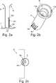
Ein Antriebsgehäuse
Ferner sind in
In der hier dargestellten Ausführungsform sind vier biegbare Leiter
Die in den Ansprüchen, der Beschreibung und den Zeichnungen offenbarten Eigenschaften können sowohl getrennt voneinander als auch in Kombination miteinander für verschiedene Ausführungsformen der beanspruchten Erfindung wesentlich sein.The characteristics disclosed in the claims, the description and the drawings may be essential both separately and in combination with each other for various embodiments of the claimed invention.
BezugszeichenlisteLIST OF REFERENCE NUMBERS
- 11
- Antriebsgehäusedrive housing
- 2, 2’2, 2 '
- Elektromotorelectric motor
- 33
- AntriebsgehäusedeckelDrive cover
- 44
- elektrische Schnittstelleelectrical interface
- 55
- BuchseRifle
- 66
- aufgeweiteter Buchsenabschnittexpanded socket section
- 77
- Führungsmittelguide means
- 88th
- Leiterplattecircuit board
- 9a–9n9a-9n
- zweite Buchsenkontaktesecond socket contacts
- 10a–10n10a-10n
- erste Buchsenkontaktefirst socket contacts
- 11a, 11b11a, 11b
- Aussparungrecess
- 1212
- Stiftpen
- 13a–13n13a-13n
- biegbare Leiterbendable ladder
- 1414
- flexibles isolierendes Materialflexible insulating material
- 1515
- Befestigungsplattemounting plate
- 1616
- Heizelementheating element
ZITATE ENTHALTEN IN DER BESCHREIBUNG QUOTES INCLUDE IN THE DESCRIPTION
Diese Liste der vom Anmelder aufgeführten Dokumente wurde automatisiert erzeugt und ist ausschließlich zur besseren Information des Lesers aufgenommen. Die Liste ist nicht Bestandteil der deutschen Patent- bzw. Gebrauchsmusteranmeldung. Das DPMA übernimmt keinerlei Haftung für etwaige Fehler oder Auslassungen.This list of the documents listed by the applicant has been generated automatically and is included solely for the better information of the reader. The list is not part of the German patent or utility model application. The DPMA assumes no liability for any errors or omissions.
Zitierte PatentliteraturCited patent literature
- US 7244912 B1[0002]US 7244912 B1[0002]
- EP 0989027 A2[0003]EP 0989027 A2[0003]
Claims (15)
Translated fromGermanPriority Applications (4)
| Application Number | Priority Date | Filing Date | Title |
|---|---|---|---|
| DE102016101441.9ADE102016101441A1 (en) | 2016-01-27 | 2016-01-27 | Adjustment system for a rearview element of a rearview device for a vehicle |
| CN201710057129.XACN107089196B (en) | 2016-01-27 | 2017-01-25 | Adjustment system for a rear-view element of a vehicle rear-view device |
| US15/416,194US11007941B2 (en) | 2016-01-27 | 2017-01-26 | Adjusting system for a rear view element of a rear view device for a vehicle |
| GB1701354.1AGB2547545B (en) | 2016-01-27 | 2017-01-27 | Adjusting system for a rear view element of a rear view device for a vehicle |
Applications Claiming Priority (1)
| Application Number | Priority Date | Filing Date | Title |
|---|---|---|---|
| DE102016101441.9ADE102016101441A1 (en) | 2016-01-27 | 2016-01-27 | Adjustment system for a rearview element of a rearview device for a vehicle |
Publications (1)
| Publication Number | Publication Date |
|---|---|
| DE102016101441A1true DE102016101441A1 (en) | 2017-07-27 |
Family
ID=58462662
Family Applications (1)
| Application Number | Title | Priority Date | Filing Date |
|---|---|---|---|
| DE102016101441.9APendingDE102016101441A1 (en) | 2016-01-27 | 2016-01-27 | Adjustment system for a rearview element of a rearview device for a vehicle |
Country Status (4)
| Country | Link |
|---|---|
| US (1) | US11007941B2 (en) |
| CN (1) | CN107089196B (en) |
| DE (1) | DE102016101441A1 (en) |
| GB (1) | GB2547545B (en) |
Families Citing this family (1)
| Publication number | Priority date | Publication date | Assignee | Title |
|---|---|---|---|---|
| US11370359B2 (en)* | 2017-06-30 | 2022-06-28 | SMR Patents S.à.r.l. | Rearview device with moveable head assembly and vehicle therewith |
Citations (3)
| Publication number | Priority date | Publication date | Assignee | Title |
|---|---|---|---|---|
| DE29620775U1 (en)* | 1996-11-29 | 1998-03-26 | Hohe GmbH & Co. KG, 97903 Collenberg | Outside mirrors for a vehicle |
| EP0989027A2 (en) | 1998-09-26 | 2000-03-29 | Reitter & Schefenacker GmbH & Co. KG | Adjusting device for a vehicle rear view mirror |
| US7244912B1 (en) | 2003-09-11 | 2007-07-17 | Magna Donnelly Mirrors North America, L.L.C. | Vehicular mirror with heater circuit module |
Family Cites Families (15)
| Publication number | Priority date | Publication date | Assignee | Title |
|---|---|---|---|---|
| US3624347A (en)* | 1970-03-16 | 1971-11-30 | Gen Motors Corp | Heated rearview mirror assembly |
| ES2019155A6 (en) | 1988-10-15 | 1991-06-01 | Mittelhaeuser Bernhard | An external rear-view mirror for motor vehicles |
| US5015824A (en) | 1989-02-06 | 1991-05-14 | Thermacon, Inc. | Apparatus for heating a mirror or the like |
| KR20010040391A (en)* | 1998-01-22 | 2001-05-15 | 브루스 알. 클루니 | Single pivot mirror assembly with security light |
| US7064882B2 (en)* | 2002-09-30 | 2006-06-20 | Gentex Corporation | Electrochromic devices having no positional offset between substrates |
| JP2002301987A (en)* | 2001-04-03 | 2002-10-15 | Ishizaki Honten:Kk | Vehicle side mirror |
| NL1019524C2 (en) | 2001-12-07 | 2003-06-11 | Iku Holding Montfoort Bv | Mirror adjustment mechanism with electrical connection. |
| US20060061008A1 (en)* | 2004-09-14 | 2006-03-23 | Lee Karner | Mounting assembly for vehicle interior mirror |
| US7329013B2 (en)* | 2002-06-06 | 2008-02-12 | Donnelly Corporation | Interior rearview mirror system with compass |
| JP2005119562A (en)* | 2003-10-17 | 2005-05-12 | Murakami Corp | Electric connection structure for attached unit for vehicle and electric connection structure for rearview mirror |
| JP4732491B2 (en)* | 2008-07-29 | 2011-07-27 | 株式会社村上開明堂 | Vehicle equipment |
| US9056584B2 (en)* | 2010-07-08 | 2015-06-16 | Gentex Corporation | Rearview assembly for a vehicle |
| JP5758250B2 (en)* | 2011-09-20 | 2015-08-05 | 株式会社村上開明堂 | door mirror |
| US9242606B2 (en)* | 2012-11-09 | 2016-01-26 | Magna Mirrors Of America, Inc. | Exterior mirror assembly with actuator |
| US9487142B2 (en)* | 2013-06-25 | 2016-11-08 | Magna Mirrors Of America, Inc. | Rearview mirror assembly for vehicle |
- 2016
- 2016-01-27DEDE102016101441.9Apatent/DE102016101441A1/enactivePending
- 2017
- 2017-01-25CNCN201710057129.XApatent/CN107089196B/enactiveActive
- 2017-01-26USUS15/416,194patent/US11007941B2/ennot_activeExpired - Fee Related
- 2017-01-27GBGB1701354.1Apatent/GB2547545B/ennot_activeExpired - Fee Related
Patent Citations (4)
| Publication number | Priority date | Publication date | Assignee | Title |
|---|---|---|---|---|
| DE29620775U1 (en)* | 1996-11-29 | 1998-03-26 | Hohe GmbH & Co. KG, 97903 Collenberg | Outside mirrors for a vehicle |
| EP0989027A2 (en) | 1998-09-26 | 2000-03-29 | Reitter & Schefenacker GmbH & Co. KG | Adjusting device for a vehicle rear view mirror |
| EP0989027B1 (en)* | 1998-09-26 | 2005-10-19 | Reitter & Schefenacker GmbH & Co. KG | Adjusting device for a vehicle rear view mirror |
| US7244912B1 (en) | 2003-09-11 | 2007-07-17 | Magna Donnelly Mirrors North America, L.L.C. | Vehicular mirror with heater circuit module |
Also Published As
| Publication number | Publication date |
|---|---|
| GB2547545B (en) | 2021-06-16 |
| CN107089196A (en) | 2017-08-25 |
| GB2547545A (en) | 2017-08-23 |
| CN107089196B (en) | 2021-09-28 |
| GB201701354D0 (en) | 2017-03-15 |
| US11007941B2 (en) | 2021-05-18 |
| US20170210296A1 (en) | 2017-07-27 |
Similar Documents
| Publication | Publication Date | Title |
|---|---|---|
| EP1518758B1 (en) | Device for detecting signals of sensors mounted in a vehicle | |
| DE102008053946B4 (en) | Shield shell unit | |
| DE19654275C2 (en) | Mounting arrangement for installing an electrical device module | |
| DE60008679T2 (en) | Fuse insert and method for its manufacture | |
| DE10304278B4 (en) | Structure for attaching a display unit to an instrument panel of an automobile | |
| DE3740593A1 (en) | WIRING HARNESS FOR A MOTOR VEHICLE | |
| DE102008009080A1 (en) | Electrical connection box | |
| DE102016116842B3 (en) | Connector for electrically connecting two electrical assemblies | |
| EP3701598B1 (en) | Cable retainer, busbar element, busbar system, mechanical connecting element for a busbar system, method for producing a busbar element, and method for producing a busbar system | |
| DE10215956B4 (en) | Sonnenblendenarmverbindungsanordnung | |
| DE2715660A1 (en) | METHOD FOR MAKING ELECTRICAL CONNECTIONS | |
| DE202013012817U1 (en) | Connector comprising a protective conductor bridge | |
| DE102015107385A1 (en) | Method for producing a camera for a motor vehicle with electrical connection of a printed circuit board and a lens housing, camera, driver assistance system and motor vehicle | |
| DE102016121047A1 (en) | LIGHTING DEVICE FOR A VEHICLE AND MANUFACTURING METHOD FOR A LIGHTING DEVICE | |
| DE60110509T2 (en) | Connection structure of electrical wires of a lamp unit | |
| DE2846825C3 (en) | Wall central | |
| DE102016101441A1 (en) | Adjustment system for a rearview element of a rearview device for a vehicle | |
| DE102015210321A1 (en) | Antenna module for a motor vehicle | |
| DE102018209235B4 (en) | Shielding shell and shielded connector | |
| DE102020004282A1 (en) | ELECTRICAL CONNECTION STRUCTURE | |
| DE69413177T2 (en) | Headlights for motor vehicles | |
| WO2014111271A1 (en) | Shielding arrangement for an electric plug connection | |
| EP1978600A1 (en) | Board assembly | |
| DE102010040595A1 (en) | Connection system and receiving unit for a control unit | |
| DE102018010157B4 (en) | Assembly with an electronic device and a coupling and method for assembling the assembly |
Legal Events
| Date | Code | Title | Description |
|---|---|---|---|
| R079 | Amendment of ipc main class | Free format text:PREVIOUS MAIN CLASS: B60R0001060000 Ipc:B60R0001072000 | |
| R163 | Identified publications notified | ||
| R084 | Declaration of willingness to licence | ||
| R012 | Request for examination validly filed |