Movatterモバイル変換


[0]ホーム

URL:


DE102016015207A1 - Actuating device and method for operating an actuating device and diaphragm pump with an actuating device and a diaphragm pump device and a blood treatment device with a diaphragm pump - Google Patents

Actuating device and method for operating an actuating device and diaphragm pump with an actuating device and a diaphragm pump device and a blood treatment device with a diaphragm pump
Download PDF

Info

Publication number
DE102016015207A1
DE102016015207A1DE102016015207.9ADE102016015207ADE102016015207A1DE 102016015207 A1DE102016015207 A1DE 102016015207A1DE 102016015207 ADE102016015207 ADE 102016015207ADE 102016015207 A1DE102016015207 A1DE 102016015207A1
Authority
DE
Germany
Prior art keywords
control
valve
fluid
diaphragm pump
working fluid
Prior art date
Legal status (The legal status is an assumption and is not a legal conclusion. Google has not performed a legal analysis and makes no representation as to the accuracy of the status listed.)
Withdrawn
Application number
DE102016015207.9A
Other languages
German (de)
Inventor
Jens Anderle
Hannes Wirtl
Current Assignee (The listed assignees may be inaccurate. Google has not performed a legal analysis and makes no representation or warranty as to the accuracy of the list.)
Fresenius Medical Care Deutschland GmbH
Original Assignee
Fresenius Medical Care Deutschland GmbH
Priority date (The priority date is an assumption and is not a legal conclusion. Google has not performed a legal analysis and makes no representation as to the accuracy of the date listed.)
Filing date
Publication date
Application filed by Fresenius Medical Care Deutschland GmbHfiledCriticalFresenius Medical Care Deutschland GmbH
Priority to DE102016015207.9ApriorityCriticalpatent/DE102016015207A1/en
Priority to PCT/EP2017/083404prioritypatent/WO2018114862A1/en
Priority to US16/470,564prioritypatent/US11441554B2/en
Priority to EP17816854.8Aprioritypatent/EP3559465B1/en
Priority to JP2019533617Aprioritypatent/JP7086965B2/en
Priority to CN201780079316.6Aprioritypatent/CN110088474B/en
Publication of DE102016015207A1publicationCriticalpatent/DE102016015207A1/en
Withdrawnlegal-statusCriticalCurrent

Links

Images

Classifications

Landscapes

Abstract

Translated fromGerman

Die Erfindung betrifft eine Betätigungseinrichtung (1) zur mechanischen Ansteuerung einer Membranpumpeneinrichtung (2), mit einem Grundkörper (4), der eine Montagefläche (7) für eine Membranpumpeneinrichtung (2) umfasst und der von einer Steuerfluidleitung (33, 35) durchsetzt ist, die sich von einem Steuerfluidanschluss (78, 79) bis zu einer Steuerfluidmündung (34, 36) erstreckt, die an der Montagefläche (7) ausmündet, wobei in der Steuerfluidleitung (33, 35) ein Steuerfluidventil (74, 75) angeordnet ist, das für eine Beeinflussung eines Querschnitts der Steuerfluidleitung (33, 35) ausgebildet ist, sowie mit einer Stelleinrichtung (9, 14), die einen an der Montagefläche (7) angeordneten Fluidaktor (38) zur Bereitstellung einer Stellbewegung und ein Arbeitsfluidventil (81, 82) umfasst, das für eine Beeinflussung eines Querschnitts einer Arbeitsfluidleitung (85, 86) ausgebildet ist, die den Grundkörper (4) durchsetzt, und wobei das Steuerfluidventil (74, 75) und das Arbeitsfluidventil (81, 82) elektrisch mit einer Steuereinrichtung (70) verbunden sind, die für eine elektrische Ansteuerung des Steuerfluidventils (74, 75) und des Arbeitsfluidventils (81, 82) ausgebildet ist. Darüber hinaus betrifft die Erfindung eine Membranpumpe, die über eine derartige Betätigungseinrichtung und eine derartige Membranpumpeneinrichtung verfügt, sowie eine Blutbehandlungsvorrichtung, die eine derartige Membranpumpe aufweist.The invention relates to an actuating device (1) for the mechanical actuation of a diaphragm pump device (2), comprising a base body (4) which comprises a mounting surface (7) for a diaphragm pump device (2) and which is penetrated by a control fluid line (33, 35). which extends from a control fluid port (78, 79) to a control fluid port (34, 36) which opens out at the mounting surface (7), wherein in the control fluid line (33, 35) a control fluid valve (74, 75) is arranged for influencing a cross section of the control fluid line (33, 35) and with an adjusting device (9, 14) which has a fluid actuator (38) arranged on the mounting surface (7) for providing an adjusting movement and a working fluid valve (81, 82) formed, which is for influencing a cross section of a working fluid line (85, 86) which passes through the base body (4), and wherein the control fluid valve (74, 75) and the working fluid idventil (81, 82) are electrically connected to a control device (70), which is designed for an electrical control of the control fluid valve (74, 75) and the working fluid valve (81, 82). Moreover, the invention relates to a diaphragm pump which has such an actuating device and such a diaphragm pump device, and a blood treatment device having such a diaphragm pump.

Description

Translated fromGerman

Die Erfindung betrifft eine Betätigungseinrichtung zur mechanischen Ansteuerung einer Membranpumpeneinrichtung und ein Verfahren zum Betreiben einer derartigen Betätigungseinrichtung. Darüber hinaus betrifft die Erfindung eine Membranpumpe, die über eine derartige Betätigungseinrichtung und eine derartige Membranpumpeneinrichtung verfügt, sowie eine Blutbehandlungsvorrichtung, insbesondere Dialysevorrichtung, die eine derartige Membranpumpe aufweist.The invention relates to an actuating device for the mechanical control of a diaphragm pump device and a method for operating such an actuating device. Moreover, the invention relates to a diaphragm pump which has such an actuating device and such a diaphragm pump device, and to a blood treatment device, in particular a dialysis device, which has such a diaphragm pump.

Zur Förderung von medizinischen Flüssigkeiten finden in der Medizintechnik Membranpumpen Verwendung. Der Vorteil von Membranpumpen liegt in der Trennung der Antriebseinheit von dem zu fördernden Fluid durch eine Membran.For the promotion of medical fluids membrane pumps are used in medical technology. The advantage of diaphragm pumps lies in the separation of the drive unit from the fluid to be delivered through a membrane.

In der Medizintechnik werden an Membranpumpen hohe Anforderungen gestellt. Für bestimmte Anwendungen sollen die Membranpumpen auch bei niedrigen Flüssen eine hohe Fördergenauigkeit haben. Eine besonders genaue Dosierung bei einer niedrigen Flussrate erfordert beispielsweise die Citratantikoagulation (CiCa-Antikoagulation) in der Dialyse.In medical technology, high demands are placed on diaphragm pumps. For certain applications, the diaphragm pumps should have a high conveying accuracy even at low flows. For example, particularly accurate dosing at a low flow rate requires citrate anticoagulation (CiCa anticoagulation) in dialysis.

Es sind Membranpumpen bekannt, die über eine nur zur einmaligen Verwendung bestimmte Membranpumpeneinrichtung verfügen. Die Membranpumpeneinrichtung dieser Membranpumpen kann als eine Einwegkassette ausgebildet sein, in der eine Ausnehmung ausgebildet ist, die von einer elastischen Membran verschlossen ist. Während der Saugphase wird die Fluidströmung aus der Pumpenkammer unterbrochen und während der Druckphase wird die Fluidströmung in die Pumpenkammer unterbrochen. Der Antrieb der elastischen Membran kann mit einer Betätigungseinrichtung erfolgen, die nicht zur einmaligen Verwendung bestimmt ist.Diaphragm pumps are known which have a diaphragm pump device intended for single use only. The membrane pump device of these membrane pumps can be designed as a disposable cassette in which a recess is formed, which is closed by an elastic membrane. During the suction phase, the fluid flow is interrupted from the pump chamber and during the pressure phase, the fluid flow is interrupted in the pump chamber. The drive of the elastic membrane can be done with an actuator that is not intended for single use.

Eine gattungsgemäße Betätigungseinrichtung wird dazu eingesetzt, eine Membranpumpeneinrichtung mechanisch anzusteuern, um ein Fluid, bei dem es sich insbesondere um eine Flüssigkeit handeln kann, von einem Eingangsanschluss der Membranpumpeneinrichtung zu einem Ausgangsanschluss der Membranpumpeneinrichtung zu fördern. Beispielhaft umfasst die Membranpumpeneinrichtung einen plattenförmig ausgebildeten Kanalkör- per, an dem ausgehend von einem Eingangsanschluss ein Saugkanal bis zu einer Pumpkammer erstreckt ist und an dem ausgehend von der Pumpkammer ein Druckkanal bis zu einem Ausgangsanschluss erstreckt ist. Dabei ist vorgesehen, dass die Pumpkammer als Ausnehmung in eine Oberfläche des Kanalkörpers eingebracht ist und von einer abdichtend am Kanalkörper angebrachten Membran verschlossen ist. Durch eine Bewegung der Membran wird ein Volumen der Pumpkammer verändert, wodurch unter der zusätzlichen Voraussetzung einer zyklischen Blockierung und Freigabe des Saugkanals und des Druckkanals ein Fluidmassenstrom für das Fluid hervorgerufen werden kann.A generic actuating device is used to mechanically control a diaphragm pump device in order to convey a fluid, which in particular can be a fluid, from an input port of the diaphragm pump device to an output port of the diaphragm pump device. By way of example, the diaphragm pump device comprises a plate-shaped channel body, on which, starting from an input connection, a suction channel extends up to a pumping chamber and on which, starting from the pumping chamber, a pressure channel extends up to an outlet connection. It is provided that the pumping chamber is introduced as a recess in a surface of the channel body and is closed by a sealing attached to the channel body membrane. By a movement of the membrane, a volume of the pumping chamber is changed, whereby under the additional requirement of a cyclic blocking and release of the suction channel and the pressure channel, a fluid mass flow for the fluid can be caused.

Die Aufgabe der Erfindung liegt darin, eine Betätigungseinrichtung zur Ansteuerung einer Membranpumpeneinrichtung zu schaffen, die eine zuverlässige Durchführung eines Fördervorgangs einer Membranpumpeneinrichtung ermöglicht, und ein Verfahren zum Betreiben einer Betätigungseinrichtung bereitzustellen, das eine zuverlässige Durchführung eines Fördervorgangs einer Membranpumpeneinrichtung erlaubt.The object of the invention is to provide an actuating device for controlling a diaphragm pump device, which enables a reliable performance of a conveying operation of a diaphragm pump device, and to provide a method for operating an actuating device, which allows reliable carrying out a conveying operation of a diaphragm pump device.

Eine weitere Aufgabe der Erfindung ist, die Fördergenauigkeit einer Membranpumpe zur Förderung einer medizinischen Flüssigkeit zu verbessern, insbesondere, eine Membranpumpe zu schaffen, die eine besonders genaue Dosierung von Fluiden, beispielsweise einer Lösung zur CiCa-Antikoagulation, auch bei sehr kleinen Flussraten erlaubt, wobei ein konstanter Fluidmassenstrom gewährleistet werden soll.Another object of the invention is to improve the delivery accuracy of a diaphragm pump for delivery of a medical fluid, in particular to provide a diaphragm pump which allows a particularly accurate dosage of fluids, such as a solution for CiCa anticoagulation, even at very low flow rates a constant fluid mass flow is to be ensured.

Darüber hinaus liegt der Erfindung die Aufgabe zugrunde, eine Blutbehandlungsvorrichtung, insbesondere eine Dialysevorrichtung, mit einer Membranpumpe bereitzustellen, die eine besonders genaue Dosierung eines Fluids, beispielsweise einer Lösung zur CiCa-Antikoagulation, auch bei sehr kleinen Flussraten mit einem konstanten Fluidmassenstrom erlaubt.In addition, the invention has for its object to provide a blood treatment device, in particular a dialysis machine, with a diaphragm pump that allows a particularly accurate dosing of a fluid, such as a solution for CiCa anticoagulation, even at very low flow rates with a constant fluid mass flow.

Die Lösung dieser Aufgaben erfolgt erfindungsgemäß mit den Merkmalen der unabhängigen Patentansprüche. Die abhängigen Ansprüche betreffen vorteilhafte Ausführungsformen der Erfindung.The solution of these objects is achieved according to the invention with the features of the independent claims. The dependent claims relate to advantageous embodiments of the invention.

Die erfindungsgemäße Betätigungseinrichtung weist einen Grundkörper auf, der eine Montagefläche für eine Membranpumpeneinrichtung umfasst und der von einer Steuerfluidleitung durchsetzt ist, die sich von einem Steuerfluidanschluss bis zu einer Steuerfluidmündung erstreckt, die an der Montagefläche ausmündet, wobei in der Steuerfluidleitung ein Steuerfluidventil angeordnet ist, das für eine Beeinflussung eines Querschnitts der Steuerfluidleitung ausgebildet ist. Ferner umfasst die Betätigungseinrichtung eine Stelleinrichtung, die einen an der Montagefläche angeordneten Fluidaktor zur Bereitstellung einer Stellbewegung und ein Arbeitsfluidventil aufweist, das für eine Beeinflussung eines Querschnitts einer Arbeitsfluidleitung ausgebildet ist, die den Grundkörper durchsetzt, und wobei das Steuerfluidventil und das Arbeitsfluidventil elektrisch mit einer Steuereinrichtung verbunden sind, die für eine elektrische Ansteuerung des Steuerfluidventils und des Arbeitsfluidventils ausgebildet ist.The actuating device according to the invention has a base body, which comprises a mounting surface for a diaphragm pump device and which is penetrated by a control fluid line extending from a control fluid port to a control fluid port, which opens at the mounting surface, wherein in the control fluid line, a control fluid valve is arranged is designed for influencing a cross section of the control fluid line. Furthermore, the actuating device comprises an actuating device, which has a fluid actuator arranged on the mounting surface for providing an adjusting movement and a working fluid valve, which is designed to influence a cross section of a working fluid line passing through the main body, and wherein the control fluid valve and the working fluid valve are electrically connected to a control device are connected, which is designed for an electrical control of the control fluid valve and the working fluid valve.

Der Grundkörper kann wahlweise einstückig oder mehrteilig ausgebildet sein und ist zumindest mit einer als Montagefläche bezeichneten Schnittstelle für die Ankopplung einer Membranpumpeneinrichtung ausgestattet. Die Montagefläche kann in Abhängigkeit von der Ausgestaltung der Membranpumpeneinrichtung als Ebene oder als dreidimensional strukturierte Fläche, insbesondere mit ebenen Bereichen, ausgebildet sein. Um eine Betätigung der, insbesondere als vollständig passives Bauelement ohne eigene Aktorik und/oder Sensorik ausgebildeten, Membranpumpeneinrichtung zu ermöglichen, ist der Grundkörper von einer Steuerfluidleitung durchsetzt, die sich von einem Steuerfluidanschluss bis zu einer Steuerfluidmündung erstreckt. Der Steuerfluidanschluss kann unmittelbar am Grundkörper angeordnet sein oder beabstandet vom Grundkörper ausgebildet sein, wobei dann beispielsweise eine Schlauchverbindung zwischen dem Steuerfluidanschluss und der Steuerfluidleitung vorgesehen sein kann. Die Steuerfluidleitung erstreckt sich ausgehend vom Steuerfluidanschluss bis zur Steuerfluidmündung, die an der Montagefläche ausmündet. An dem Steuerfluidanschluss kann beispielsweise eine Steuerfluid- quelle, insbesondere eine Druckluftquelle, oder eine Steuerfluidsenke, insbesondere ein Vakuumerzeuger, angeschlossen werden. Mit Hilfe des Steuerfluids wird eine Bewegung einer Pumpmembran der Membranpumpeneinrichtung durch zyklische oder azyklische Druckbeaufschlagung und/oder Unterdruckbeaufschlagung hervorgerufen, wodurch die Pumpmembran ein zu förderndes Fluid in eine Pumpkammer ansaugen und/oder aus der Pumpkammer ausstoßen/austragen kann. Um Einfluss auf einen Steuerfluidstrom nehmen zu können, ist in der Steuerfluidleitung ein Steuerfluidventil angeordnet, das für eine Beeinflussung eines Querschnitts der Steuerfluidleitung, insbesondere zwischen einer Schließstellung für eine vollständige Blockierung der Steuerfluidleitung und einer Öffnungsstellung für eine vollständige Freigabe des Querschnitts der Steuerfluidleitung, ausgebildet ist. The main body may optionally be formed in one piece or in several parts and is equipped at least with an interface designated as a mounting surface for the coupling of a diaphragm pump device. Depending on the configuration of the diaphragm pump device, the mounting surface can be designed as a plane or as a three-dimensionally structured surface, in particular with planar regions. In order to enable actuation of the diaphragm pump device, designed in particular as a completely passive component without its own actuator system and / or sensor, the main body is penetrated by a control fluid line which extends from a control fluid port to a control fluid port. The control fluid connection can be arranged directly on the base body or spaced from the base body, in which case, for example, a hose connection between the control fluid connection and the control fluid line can be provided. The control fluid line extends from the control fluid port to the control fluid port that terminates at the mounting surface. For example, a control fluid source, in particular a compressed air source, or a control fluid sink, in particular a vacuum generator, can be connected to the control fluid port. With the aid of the control fluid, a movement of a pump membrane of the membrane pump device is caused by cyclic or acyclic pressurization and / or negative pressure, whereby the pump membrane can suck a fluid to be delivered into a pumping chamber and / or discharge / discharge it. In order to be able to influence a control fluid flow, a control fluid valve is arranged in the control fluid line, which is designed to influence a cross section of the control fluid line, in particular between a closed position for a complete blockage of the control fluid line and an open position for a complete release of the cross section of the control fluid line ,

Dem Grundkörper ist weiterhin eine Stelleinrichtung zugeordnet, die für eine mechanische Betätigung eines an der Membranpumpeneinrichtung vorgesehenen Membranventils ausgebildet ist. Dieses Membranventil kann beispielsweise fluidisch kommunizierend mit der ebenfalls in der Membranpumpeneinrichtung ausgebildeten Pumpkammer verbunden sein und für eine Steuerung eines Fluidstroms in die Pumpkammer oder aus der Pumpkammer eingerichtet sein. Zur Betätigung dieses Membranventils weist die Stelleinrichtung einen an der Montagefläche angeordneten Fluidaktor auf, bei dem es sich beispielhaft um einen kompakt bauenden Pneumatikzylinder handelt. Die Stelleinrichtung umfasst ein bewegliches Aktorglied, das linear und/oder rotatorisch zwischen einer Ruhestellung und einer Funktionsstellung bewegt werden kann und insbesondere in der Funktionsstellung über die Montagefläche abragt. Hierdurch kann eine Membran des gegenüberliegend anbringbaren Membranventils der Membranpumpeneinrichtung lokal deformiert werden, um beispielsweise eine Schließstellung dieses Membranventils herbeizuführen. Ferner kann vorgesehen sein, dass das Membranventil sich in einer Öffnungsstellung befindet, wenn das Aktorglied die, insbesondere flächenbündig mit der Montagefläche ausgebildete, Ruhestellung einnimmt. Für eine fluidische Ansteuerung des Fluidaktors der Stelleinrichtung ist ein Arbeitsfluidventil vorgesehen, das einer Arbeitsfluidleitung zugeordnet ist, die den Grundkörper durchsetzt. Dabei ist das Arbeitsfluidventil beispielhaft zwischen einer Schließstellung für eine vollständige Blockierung der Arbeitsfluidleitung und einer Öffnungsstellung für eine vollständige Freigabe des Querschnitts der Arbeitsfluidleitung umschaltbar oder einstellbar. Eine Bereitstellung des Arbeitsfluids für die Betätigung des Fluidaktors kann beispielhaft über einen separat ausgebildeten Arbeitsfluidanschluss erfolgen, an dem eine Fluidquelle oder eine Fluidsenke für eine Bereitstellung eines druckbeaufschlagten Arbeitsfluids oder eines Unterdrucks angeschlossen werden können. Alternativ kann eine Verbindung der Arbeitsfluidleitung mit dem Steuerfluidanschluss vorgesehen sein.The main body is further associated with an actuating device which is designed for a mechanical actuation of a membrane valve provided on the diaphragm valve. This diaphragm valve can be connected, for example, in fluidic communication with the pumping chamber, which is likewise embodied in the diaphragm pump device, and can be set up to control a fluid flow into the pumping chamber or out of the pumping chamber. To actuate this diaphragm valve, the adjusting device has a fluid actuator arranged on the mounting surface, which is an example of a compact pneumatic cylinder. The adjusting device comprises a movable actuator member which can be moved linearly and / or rotationally between a rest position and a functional position and, in particular in the functional position, protrudes beyond the mounting surface. In this way, a membrane of the diaphragm valve opposite the attachable diaphragm pump device can be locally deformed, for example, to bring about a closed position of this diaphragm valve. Furthermore, it can be provided that the diaphragm valve is in an open position when the actuator member assumes the, in particular flush with the mounting surface formed, rest position. For a fluidic control of the fluid actuator of the adjusting device, a working fluid valve is provided, which is assigned to a working fluid line, which passes through the base body. In this case, the working fluid valve is exemplified switchable or adjustable between a closed position for complete blocking of the working fluid line and an open position for complete release of the cross section of the working fluid line. A provision of the working fluid for the actuation of the fluid actuator can take place, for example, via a separately designed working fluid connection, to which a fluid source or a fluid sink can be connected for providing a pressurized working fluid or a negative pressure. Alternatively, a connection of the working fluid line may be provided with the control fluid port.

Sowohl das Steuerfluidventil als auch das Arbeitsfluidventil sind elektrisch mit einer Steuereinrichtung verbunden, die für eine elektrische Ansteuerung des Steuerfluidventils und des Arbeitsfluidventils ausgebildet ist. Beispielhaft kann es sich bei der Steuereinrichtung um einen Mikroprozessor oder Mikrocontroller handeln, die zur Abarbeitung eines vorgebbaren Steuerprogramms für das Steuerfluidventil und das Arbeitsfluidventil ausgebildet sind. Die Steuereinrichtung kann ihrerseits für eine Kommunikation mit einer übergeordneten Steueranordnung, insbesondere einer speicherprogrammierbaren Steuerung, vorgesehen sein und hierfür eine geeignete Kommunikationsschnittstelle, insbesondere eine Multipol- Schnittstelle oder eine Busschnittstelle, umfassen.Both the control fluid valve and the working fluid valve are electrically connected to a control device, which is designed for an electrical control of the control fluid valve and the working fluid valve. By way of example, the control device may be a microprocessor or microcontroller, which are designed to process a predefinable control program for the control fluid valve and the working fluid valve. The control device can in turn be provided for communication with a superordinate control arrangement, in particular a programmable logic controller, and for this purpose comprise a suitable communication interface, in particular a multipole interface or a bus interface.

Eine bevorzugte Ausführungsform der Erfindung sieht vor, dass am Grundkörper ein Steuerfluid-Drucksensor angeordnet ist, der elektrisch mit der Steuereinrichtung verbunden ist und der für eine Erfassung eines Steuerfluiddrucks ausgebildet ist. Der Steuerfluid-Drucksensor kann über eine Fluidleitung fluidisch kommunizierend mit der Steuerfluidleitung verbunden sein oder in der Steuerfluidleitung angeordnet sein oder benachbart zur Steuerfluidmündung angeordnet sein und dient zur Erfassung des Steuerfluiddrucks, der bei Kopplung der Betätigungseinrichtung mit einer Membranpumpeneinrichtung auf die Pumpmembran aufgebracht werden kann. Anhand des gemessenen Steuerfluiddrucks und/oder einer zeitlichen Ableitung des gemessenen Steuerfluiddrucks können in der Steuereinrichtung Rückschlüsse darauf gezogen werden, in welcher Weise die Pumpmembran deformiert ist und ein Fördervorgang für das mit Hilfe der Membranpumpeneinrichtung zu fördernde Fluid abläuft.A preferred embodiment of the invention provides that the base body, a control fluid pressure sensor is arranged, which is electrically connected to the control device and which is designed for detecting a control fluid pressure. The control fluid pressure sensor may be fluidically communicating with the control fluid conduit via a fluid conduit or disposed within the control fluid conduit or adjacent to the control fluid orifice and for sensing the control fluid pressure that may be applied to the pumping diaphragm upon coupling of the actuator to a diaphragm pumping device. Based on the measured control fluid pressure and / or a time derivative of the measured Control fluid pressure conclusions can be drawn in the control device in which way the pumping membrane is deformed and a delivery process for the fluid to be pumped by means of the diaphragm pump device runs.

Bei einer Weiterbildung der Erfindung ist vorgesehen, dass der Arbeitsfluidleitung ein Arbeitsfluid-Drucksensor angeordnet ist, der elektrisch mit der Steuereinrichtung verbunden ist und der für eine Erfassung eines Arbeitsfluiddrucks ausgebildet ist. Der Arbeitsfluid-Drucksensor kann über eine Sensorleitung fluidisch kommunizierend mit der Arbeitsfluidleitung verbunden sein oder in der Arbeitsfluidleitung angeordnet sein. Ein Sensorsignal des Arbeitsfluid-Drucksensors wird entweder im Arbeitsfluidventil und/oder in der Steuereinrichtung verarbeitet und dient insbesondere zur Druckregelung des Arbeitsfluiddrucks, der an den Fluidaktor bereitgestellt wird. Bei einer Bereitstellung des Sensorsignals des Arbeitsfluid-Drucksensors an die Steuereinrichtung kann unter zusätzlicher Einbeziehung des Sensorsignals des Steuerfluid-Drucksensors eine besonders exakte Ansteuerung des Fluidaktors erfolgen, der beispielhaft zur Betätigung eines Membranventils der Membranpumpeneinrichtung ausgebildet ist.In a further development of the invention, it is provided that the working fluid line is arranged a working fluid pressure sensor, which is electrically connected to the control device and which is designed for detecting a working fluid pressure. The working fluid pressure sensor may be fluidly communicating with the working fluid line via a sensor line or disposed in the working fluid line. A sensor signal of the working fluid pressure sensor is processed either in the working fluid valve and / or in the control device and serves in particular for pressure control of the working fluid pressure which is provided to the fluid actuator. In a provision of the sensor signal of the working fluid pressure sensor to the control device can be carried out with additional inclusion of the sensor signal of the control fluid pressure sensor, a particularly accurate control of the fluid actuator, which is designed for example for actuating a diaphragm valve of the diaphragm pump device.

In weiterer Ausgestaltung der Erfindung ist vorgesehen, dass an der Montagefläche eine konkave Steuerkammer als Bewegungsraum für eine Pumpmembran ausgebildet ist und dass die Steuerfluidmündung an einer Oberfläche der Steuerkammer aus- mündet. Mit der konkav ausgebildeten Steuerkammer wird ein vorteilhafter Pumpenhub für die an der Membranpumpeneinrichtung ausgebildete Membranpumpe ermöglicht, da die Membran der Membranpumpe zusätzlich zu einem ohnehin möglichen konkaven Deformationszustand bei Druckbeaufschlagung der Steuerfluidleitung auch in einen konvexen Deformationszustand gebracht werden kann, der bei einer Unterdruckbeaufschlagung der Steuerkammer auftreten kann. Vorzugsweise ist in der Steuerkammer ein fluiddurchlässiger Formkörper vorgesehen, der beabstandet von der Oberfläche der Steuerkammer angeordnet ist und der bei einer Unterdruckbeaufschlagung der Membran der Membranpumpe als Anlagefläche für die Membran dient. Ein Raumvolumen zwischen der Oberfläche der Steuerkammer und einer der Membran zugewandten Anlagefläche des Formkörpers dient als Arbeitsraum für das an der Steuerfluidmündung bereitstellbare Steuerfluid, das beispielsweise nach einer Unterdruckbeaufschlagung der Steuerkammer und einer dadurch bedingten flächigen Anlage der Membran an der Anlagefläche für einen Austragvorgang der Membranpumpe genutzt werden soll.In a further embodiment of the invention it is provided that on the mounting surface a concave control chamber is designed as a movement space for a pumping diaphragm and that the control fluid orifice opens out at a surface of the control chamber. With the concave control chamber, an advantageous pump stroke is made possible for the diaphragm pump formed on the diaphragm pump device, since the membrane of the diaphragm pump can be brought into a convex deformation state in addition to an already possible concave deformation state upon pressurization of the control fluid line, which occur at a negative pressure of the control chamber can. Preferably, a fluid-permeable molded body is provided in the control chamber, which is arranged at a distance from the surface of the control chamber and which serves in a negative pressure of the membrane of the diaphragm pump as a contact surface for the membrane. A volume of space between the surface of the control chamber and a contact surface of the shaped body facing the diaphragm serves as a working space for the control fluid which can be provided at the control fluid orifice and which, for example, is used for a discharge process of the diaphragm pump after a negative pressure on the control chamber and a consequent contact of the membrane with the membrane shall be.

Bevorzugt ist im Grundkörper eine Unterdruckleitung ausgebildet, die sich von einem Unterdruckanschluss bis zur Steuerkammer oder zur Steuerfluidleitung erstreckt und in der ein Unterdruckventil angeordnet ist, das für eine Beeinflussung eines Querschnitts der Unterdruckleitung ausgebildet ist, wo- bei das Unterdruckventil elektrisch mit der Steuereinrichtung verbunden ist. In Abhängigkeit von der Gestaltung der Steuerkammer und des darin gegebenenfalls aufgenommenen Formkörpers kann wahlweise vorgesehen sein, dass die Unterdruckleitung unmittelbar an der Oberfläche der Steuerkammer ausmündet oder fluidisch kommunizierend mit der Steuerfluidleitung verbunden ist. Durch eine zyklische Wechselbeaufschlagung der Steuerkammer und der daran ankoppelbaren Membran der Membranpumpeneinrichtung wird eine Pumpbewegung für die Membran zwischen einem konkaven Deformationszustand bei Druckbeaufschlagung der Steuerfluidleitung und konvexen Deformationszustand und damit ein maximaler Pumpenhub ermöglicht. Bei der Unterdruckleitung handelt es sich ebenfalls um eine Steuerfluidleitung.Preferably, in the base body, a vacuum line is formed, which extends from a vacuum port to the control chamber or the control fluid line and in which a vacuum valve is arranged, which is designed to influence a cross section of the vacuum line, wherein the vacuum valve is electrically connected to the control device , Depending on the design of the control chamber and the molded body optionally accommodated therein, it may optionally be provided that the vacuum line opens directly on the surface of the control chamber or is connected in fluidic communication with the control fluid line. By cyclically alternating the control chamber and the diaphragm of the diaphragm pump device which can be coupled thereto, a pumping movement is made possible for the diaphragm between a concave deformation state when pressure is applied to the control fluid line and convex deformation state and thus a maximum pump stroke. The vacuum line is also a control fluid line.

Vorteilhaft ist es, wenn die Arbeitsfluidleitung fluidisch kommunizierend mit dem Steuerfluidanschluss verbunden ist.It is advantageous if the working fluid line is connected fluidically communicating with the control fluid port.

Bei einer vorteilhaften Weiterbildung der Erfindung ist vorgesehen, dass die Steuereinrichtung einen Beobachteralgorithmus umfasst, der für eine Ermittlung eines Fluidmassenstroms in einer Membranpumpeneinrichtung anhand des Drucksignals des Steuerfluid-Drucksensors ausgebildet ist. Die Aufgabe des Beobachteralgorithmus besteht darin, den Fluidmassenstrom in der Membranpumpeneinrichtung zu bestimmen, ohne dass hierfür eine Sensoreinrichtung unmittelbar in der Membranpumpeneinrichtung integriert ist. Der Beobachteralgorithmus kann beispielsweise als Gleichungssystem oder als neuronales Netzwerk ausgebildet sein. Vorzugsweise wird der Beobachteralgorithmus mit. Hilfe einer Referenzanordnung, die die Betätigungseinrichtung und die daran angebrachten Membranpumpeneinrichtung sowie einen externen, präzisen Durchflussmesser umfasst, durch Abgleich der Signale des Steuerfluid-Drucksensors und des externen Durchflussmessers kalibriert.In an advantageous development of the invention, it is provided that the control device comprises an observer algorithm, which is designed for ascertaining a fluid mass flow in a diaphragm pump device on the basis of the pressure signal of the control fluid pressure sensor. The task of the observer algorithm is to determine the fluid mass flow in the diaphragm pump device without a sensor device being integrated directly in the diaphragm pump device for this purpose. The observer algorithm can be designed, for example, as a system of equations or as a neural network. Preferably, the observer algorithm with. Using a reference arrangement, which comprises the actuator and the attached diaphragm pump device and an external, precise flow meter calibrated by adjusting the signals of the control fluid pressure sensor and the external flow meter.

Bei einer besonders bevorzugten Ausführungsform ist am Grundkörper eine erste Stelleinrichtung mit einem ersten Arbeitsfluidventil und eine zweite Stelleinrichtung mit einem zweiten Arbeitsfluidventil angeordnet sind, wobei das erste Arbeitsfluidventil als Schaltventil ausgebildet ist und wobei das zweite Arbeitsfluidventil als Proportionalventil, insbesondere als Druckregelventil, ausgebildet ist. Hierdurch kann die Betätigungseinrichtung bei angekoppelter Membranpumpeneinrichtung sowohl Einfluss auf einen Fluidzustrom in die Pumpkammer als auch Einfluss auf einen Fluidabstrom aus der Pumpkammer nehmen. Vorzugsweise ist die Steuereinrichtung derart ausgebildet, dass sie eine zyklisch wiederkehrende, gegensinnige Ansteuerung der beiden Stelleinrichtungen in Abhängigkeit von einer Bereitstellung von Steuerfluid an die Steuerkammer ermöglicht. Bevorzugt ist vorgesehen, dass die erste Stelleinrichtung in einem gesteuerten Betrieb betrieben wird, während die zweite Stelleinrichtung in einem geregelten Betrieb, insbesondere in Abhängigkeit von einem Sensorsignal eines dem zweiten Arbeitsfluidventil zugeordneten Arbeitsfluid-Drucksensors, betrieben wird. In dem geregelten Betrieb wirkt das zweite Arbeitsfluidventil als Druckregelventil. Hierdurch kann insbesondere eine Einhaltung eines engen begrenzten Durchflussintervalls für einen Fluidmassenstrom, der von der Membranpumpeneinrichtung während eines Pumpenhubs gefördert wird, gewährleistet werden.In a particularly preferred embodiment, a first actuating device with a first working fluid valve and a second actuating device with a second working fluid valve are arranged on the base body, wherein the first working fluid valve is designed as a switching valve and wherein the second working fluid valve as a proportional valve, in particular as a pressure control valve is formed. As a result, the actuating device can have an influence on a fluid flow into the pumping chamber as well as an influence on a fluid outflow from the pumping chamber when the diaphragm pump device is coupled. Preferably, the control device is designed such that it has a cyclically recurring, opposing control of the two actuating devices in response to a provision of control fluid to the control chamber allows. It is preferably provided that the first actuating device is operated in a controlled mode, while the second actuating device is operated in a regulated mode, in particular as a function of a sensor signal of a working fluid pressure sensor assigned to the second working fluid valve. In the controlled operation, the second working fluid valve acts as a pressure regulating valve. In particular, compliance with a narrow, limited flow interval for a fluid mass flow, which is conveyed by the diaphragm pump device during a pump stroke, can thereby be ensured.

Bei dem erfindungsgemäßen Verfahren zum Betreiben einer Betätigungseinrichtung erfolgt eine Ansteuerung des Arbeitsfluidventils durch die Steuereinrichtung, die mit einem Beobachteralgorithmus einen Fluidmassenstrom in einer Membranpumpeneinrichtung anhand der Drucksignale eines Steuerfluid-Drucksensors ermittelt und die einen Drucksollwert für das Arbeitsfluidventil in Abhängigkeit vom ermittelten Fluidmassenstrom bestimmt, um während einer Austragphase der Membranpumpeneinrichtung einen konstanten Fluidmassenstrom zu gewährleisten.In the method according to the invention for operating an actuating device, control of the working fluid valve is effected by the control device which uses an observer algorithm to determine a fluid mass flow in a diaphragm pump device on the basis of the pressure signals of a control fluid pressure sensor and which determines a pressure setpoint for the working fluid valve as a function of the ascertained fluid mass flow a discharge phase of the diaphragm pump device to ensure a constant fluid mass flow.

Bei einer Weiterbildung des Verfahrens ist vorgesehen, dass das die Steuereinrichtung das Steuerfluidventil und das Unterdruckventil während einer Austragphase der Membranpumpeneinrichtung derart ansteuert, dass die Steuerfluidleitung und die Unterdruckleitung gesperrt sind. Somit erfolgt der Austrag des Fluids aus der Pumpkammer der Membranpumpe ohne einen weiteren Zustrom von Steuerfluid in die Steuerkammer, sondern vielmehr aufgrund des bei Beginn der Austragphase in der Steuerkammer vorliegenden Steuerfluiddrucks in Verbindung mit der inneren Spannung in der deformierten Membran der Membranpumpe. Somit kann der Steuerfluiddruck als Maß für die Volumenänderung in der Steuerkammer und somit indirekt als Maß für den Fluidmassenstrom aus der Pumpkammer der Membranpumpe genutzt werden.In a development of the method, it is provided that the control device activates the control fluid valve and the vacuum valve during a discharge phase of the diaphragm pump device such that the control fluid line and the vacuum line are blocked. Thus, the discharge of the fluid from the pumping chamber of the diaphragm pump takes place without a further influx of control fluid into the control chamber, but rather due to the control fluid pressure present at the start of the discharge phase in the control chamber in conjunction with the internal stress in the deformed diaphragm of the diaphragm pump. Thus, the control fluid pressure can be used as a measure of the change in volume in the control chamber and thus indirectly as a measure of the fluid mass flow from the pumping chamber of the diaphragm pump.

Die erfindungsgemäße Membranpumpeneinrichtung, die von der erfindungsgemäßen Betätigungseinrichtung mechanisch angesteuert werden kann, weist vorzugsweise einen Pumpenkammerkörper auf, in dem eine Ausnehmung ausgebildet ist, die zur Bildung einer Pumpenkammer von einer elastischen Membran verschlossen ist. Darüber hinaus umfasst die Membranpumpeneinrichtung einen Zustrompfad, der einen Eingangsanschluss mit einer Einlassöffnung der Pumpenkammer verbindet, und einen Abstrompfad, der eine Auslassöffnung der Pumpenkammer mit einem Ausgangsanschluss verbindet. In dem Zustrompfad ist ein Einlassventil und in dem Abstrompfad ist ein Auslassventil vorgesehen, um die Flüssigkeitsströmung in dem Zustrom- bzw. Abstrompfad beeinflussen zu können.The membrane pump device according to the invention, which can be controlled mechanically by the actuating device according to the invention, preferably has a pump chamber body, in which a recess is formed, which is closed by an elastic membrane to form a pump chamber. In addition, the diaphragm pump device includes an inflow path connecting an input port to an inlet port of the pump chamber and an exhaust path connecting an outlet port of the pump chamber to an output port. In the inflow path is an inlet valve and in the Abstrompfad an exhaust valve is provided to influence the flow of liquid in the inflow or Abstrompfad can.

Die Membranpumpeneinrichtung oder ein Teil der Membranpumpeneinrichtung kann als eine zur einmaligen Verwendung bestimmte Kassette ausgebildet, die für die Verwendung mit der Betätigungseinrichtung der Membranpumpe bestimmt ist. Die Membranpumpeneinrichtung kann als eine an eine Montagefläche der Betätigungseinrichtung ankoppelbare Einrichtung ausgebildet sein. Membranpumpeneinrichtung und Betätigungseinrichtung können aber auch im Gebrauch nicht voneinander trennbare Einrichtungen sein.The diaphragm pump device or a part of the diaphragm pump device can be designed as a cassette intended for single use, which is intended for use with the actuating device of the diaphragm pump. The diaphragm pump device can be designed as a device that can be coupled to a mounting surface of the actuating device. However, diaphragm pump device and actuating device can also be inseparable from one another even in use.

Die erfindungsgemäße Membranpumpe umfasst die erfindungsgemäße Betätigungseinrichtung und die erfindungsgemäße Pumpeneinrichtung.The diaphragm pump according to the invention comprises the actuating device according to the invention and the pump device according to the invention.

Die Membranpumpe kann vorteilhafterweise in der Medizintechnik Verwendung finden. Vorteile ergeben sich aber auch bei einer Verwendung in anderen Bereichen der Technik. Eine besonders bevorzugte Verwendung ist der Einsatz der Membranpumpe in einer Blutbehandlungsvorrichtung, insbesondere Dialysevorrichtung, mit einem Behältnis zur Bereitstellung einer medizinischen Flüssigkeit, insbesondere einer Antikoagulations-Lösung, die mit einer besonders hohen Fördergenauigkeit bei einer relativ geringen Flussrate gefördert werden soll.The diaphragm pump can advantageously be used in medical technology. However, advantages also arise when used in other areas of technology. A particularly preferred use is the use of the membrane pump in a blood treatment device, in particular a dialysis device, with a container for providing a medical fluid, in particular an anticoagulation solution, which is to be delivered with a particularly high delivery accuracy at a relatively low flow rate.

Nachfolgend wird ein Ausführungsbeispiel einer Membranpumpe, die eine Pumpeneinrichtung und eine Betätigungseinrichtung umfasst, im Einzelnen beschrieben.Hereinafter, an embodiment of a diaphragm pump comprising a pump device and an actuator will be described in detail.

Es zeigen:

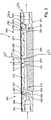
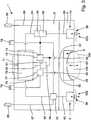
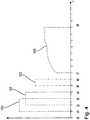
  • 1 eine Schnittdarstellung eines Teils einer Betätigungseinrichtung mit einer Steuerkammer und einer Stelleinrichtung,
  • 2 eine Schnittdarstellung einer Membranpumpeneinrichtung,
  • 3 ein schematisches Schaltbild der Betätigungseinrichtung gemäß der1,
  • 4 ein Steuerdiagramm für die Betätigungseinrichtung gemäß der1.
Show it:
  • 1 a sectional view of a part of an actuating device with a control chamber and an adjusting device,
  • 2 a sectional view of a diaphragm pump device,
  • 3 a schematic diagram of the actuator according to the 1 .
  • 4 a control diagram for the actuator according to the 1 ,

Die in der1 dargestellte Betätigungseinrichtung1 ist für eine mechanische Ansteuerung einer in2 dargestellten Membranpumpeneinrichtung2 vorgesehen, wobei ein nicht dargestellter mechanischer Verbund aus der Betätigungseinrichtung1 und der Membranpumpeneinrichtung2 eine Fluidförderung eines vorzugsweise flüssigen Fluids bei vollständiger Trennung des zu fördernden Fluids von der Betätigungseinrichtung1 ermöglicht.The in the 1 illustrated actuator 1 is for a mechanical control of an in 2 illustrateddiaphragm pump device 2 provided, wherein an unillustrated mechanical composite of the actuator 1 and the diaphragm pump device 2 a fluid delivery of a preferably liquid fluid with complete separation of the fluid to be delivered from the actuator 1 allows.

Die Betätigungseinrichtung1 ist gemäß der Darstellung der1 rein exemplarisch spiegelsymmetrisch zu einer Spiegelebene ausgebildet, die senkrecht zur Darstellungsebene der1 ausgerichtet ist und die eine Mittelachse3 umfasst. Die Betätigungseinrichtung1 umfasst einen Grundkörper4, der beispielhaft quaderförmig ausgebildet ist und der insbesondere als Kunststoffspritzgussteil hergestellt sein kann. An einer beispielhaft eben ausgebildeten Oberseite5 des Grundkörpers4 ist eine Steuerbaugruppe6 angebracht, die nachstehend im Zusammenhang mit der3 näher beschrieben wird. Eine exemplarisch zumindest im Wesentlichen eben ausgebildete Unterseite des Grundkörpers4 dient als Montagefläche7 für die in2 dargestellte und ebenfalls nachstehend näher beschriebene Membranpumpeneinrichtung2. The actuating device 1 is according to the representation of 1 purely exemplarily formed mirror-symmetrically to a mirror plane perpendicular to the plane of the 1 is aligned and the onecentral axis 3 includes. The actuating device 1 includes amain body 4 , which is formed by way of example parallelepiped and which can be made in particular as a plastic injection molded part. On an example just trainedtop 5 of thebasic body 4 is acontrol assembly 6 attached hereafter, in connection with the 3 will be described in more detail. An exemplarily at least substantially planar underside of thebase body 4 serves as a mountingsurface 7 for the in 2 represented and also described in more detail belowdiaphragm pump device 2 ,

Wie der teilweise geschnittenen Darstellung der1 entnommen werden kann, sind im Grundkörper4 eine Steuerkammer8 sowie eine Stelleinrichtung9 angeordnet. Dabei ist die Steuerkammer8 für eine Betätigung einer Membran201 einer Membranpumpe200, die in der Membranpumpeneinrichtung2 ausgebildet ist, vorgesehen. Die Stelleinrichtung 9 dient zur Ansteuerung eines Membranventils202,203, das ebenfalls in der Membranpumpeneinrichtung2 ausgebildet ist.Like the partially cut representation of the 1 can be taken, are in the main body 4 a control chamber 8th and anadjusting device 9 arranged. Here is the control chamber 8th for actuation of a membrane 201 adiaphragm pump 200 in thediaphragm pump device 2 is formed, provided. The adjustingdevice 9 serves to control adiaphragm valve 202 . 203 also in thediaphragm pump device 2 is trained.

Die Steuerkammer8 ist beispielhaft als rotationssymmetrische Ausnehmung in der Montagefläche7 ausgebildet, wobei die Mittelachse3 als Rotationsachse für ein Profil der Steuerkammer8 vorgesehen ist. Die Steuerkammer8 ist im Wesentlichen mit einem napfförmigen Querschnitt versehen und weist einen kreisrunden Bodenbereich10, einen konusabschnittsförmigen Wandbereich11, eine kreisringförmige Kontaktfläche12 und einen daran angrenzenden, konusabschnittsförmigen Auslaufbereich15 auf. Der Bodenbereich10 wird beispielhaft von einer Oberfläche eines kreisringförmigen Dichtelements16 gebildet, das in einer an die Steuerkammer8 angrenzenden Ausnehmung 17 eingesetzt ist und das bezogen auf die Mittelachse3 ein L-förmiges Profil aufweist. Das Dichtelement16 liegt mit einer kreiszylindrischen Außenoberfläche18 flächig an einer gegenüberliegenden, nicht bezeichneten inneren Oberfläche der Ausnehmung17 an und weist an einem kürzeren L-Schenkel einen radial nach innen weisenden Ringbund19 auf, der für eine abdichtende Anlage an einer Außenoberfläche eines rotationssymmetrisch zur Mittelachse3 ausgebildeten Kanalteils20 vorgesehen ist. Um eine eindeutige Platzierung des Dichtelements16 und des Kanalteils20 zu gewährleisten weist die Ausnehmung17 einen radial nach innen vorspringenden Ringbund21 auf, an dem eine axiale, kreisringförmige Stirnseite22 des Dichtelement16 formschlüssig anliegt. Das Kanalteil20 liegt seinerseits mit einer Stufe23 an der Stirnseite22 an. Sowohl das Dichtelement16 als auch das Kanalteil20 sind jeweils von einer zentrischen Ausnehmung24,25 durchsetzt, die als Bestandteil einer Steuerfluidleitung33 anzusehen sind.The control chamber 8th is exemplary as a rotationally symmetrical recess in the mountingsurface 7 formed, wherein thecentral axis 3 as a rotation axis for a profile of the control chamber 8th is provided. The control chamber 8th is essentially provided with a cup-shaped cross section and has acircular bottom portion 10 , a conesection wall area 11 , acircular contact surface 12 and an adjacent cone-shapedoutlet area 15 on. Thefloor area 10 is exemplified by a surface of anannular sealing element 16 formed in one to the control chamber 8thadjacent recess 17 is inserted and related to thecentral axis 3 has an L-shaped profile. The sealingelement 16 lies with a circular cylindricalouter surface 18 flat on an opposite, not designated inner surface of therecess 17 and at a shorter L-leg has a radially inwardly facingannular collar 19 on, which is for a sealing abutment on an outer surface of a rotationally symmetrical to thecentral axis 3 trainedchannel part 20 is provided. To ensure a clear placement of the sealingelement 16 and thechannel part 20 to ensure has the recess 17 a radially inwardly projectingannular collar 21 on, on which an axial, annular end face 22 of the sealingelement 16 positive fit. Thechannel part 20 is in turn with astep 23 at the front 22 at. Both the sealingelement 16 as well as thechannel part 20 are each of acentral recess 24 . 25 interspersed as part of acontrol fluid line 33 to be considered.

In der Steuerkammer8 ist ein Formkörper26 aufgenommen, der rein exemplarisch rotationssymmetrisch zur Mittelachse3 ausgebildet ist und umfasst einen im Wesentlichen als Kugelschalenabschnitt ausgeführten Hauptkörper27, einen hiervon radial nach außen abragenden Ringbund28 und einen koaxial zur Mittelachse3 ausgerichteten Stützring29. Der Hauptkörper27 ist von einer zentral angeordneten Ausnehmung30 durchsetzt und bildet an einer dem Stützring29 abgewandten Oberfläche eine als Kugelkalotte geformte Anlagefläche31 aus.In the control chamber 8th is a shapedbody 26 taken, the purely exemplary rotationally symmetric to thecentral axis 3 is formed and comprises a substantially executed as a spherical shell portionmain body 27 , an annular collar projecting radially outward therefrom 28 and a coaxial with thecentral axis 3 alignedsupport ring 29 , Themain body 27 is from a centrally located recess 30 interspersed and forms at one of thesupport ring 29 the surface facing away from a formed as a sphericalcap contact surface 31 out.

Der Ringbund28 liegt an der Kontaktfläche12 der Steuerkammer8 an, während der Stützring29 stirnseitig am Bodenbereich10 der Steuerkammer8 abgestützt ist. Die Anlagefläche31 dient als Begrenzung für einen Raumabschnitt, der als Membranarbeitsbereich32 bezeichnet wird und begrenzt bei Anbringung der Membranpumpeneinrichtung2 an der Betätigungseinrichtung1 eine Deformation der Membran201 der Membranpumpe200. Die Ausnehmung30 im Formkörper26 dient als Steuerfluidmündung34.Thering collar 28 lies at thecontact surface 12 the control chamber 8th on while thesupport ring 29 on the front side at thebottom area 10 the control chamber 8th is supported. Thecontact surface 31 serves as a boundary for a section of space that serves as amembrane working area 32 is designated and limited when attaching thediaphragm pump device 2 on the actuator 1 a deformation of themembrane 201 thediaphragm pump 200 , The recess 30 in themolding 26 serves as acontrol fluid outlet 34 ,

Benachbart zur Steuerkammer8 ist im Grundkörper4 die Stelleinrichtung9 angeordnet, bei der es sich beispielhaft um einen fluidisch betreibbaren Linearaktor handelt. Exemplarisch umfasst die Stelleinrichtung9 ein linearbeweglich in einer Ausnehmung37 aufgenommenes Stellglied38, das zur Betätigung des Membranventils202,203 der Membranpumpeneinrichtung2 vorgesehen ist. Das Stellglied38 wird beispielhaft ohne eine Bereitstellung von druckbeaufschlagtem Fluid durch Einwirkung einer nicht dargestellten Feder in eine nicht dargestellte Ruheposition verlagert. Gemäß der Darstellung der1 befindet sich das Stellglied38 durch Bereitstellung von druckbeaufschlagtem Fluid in einer Funktionsposition. Das Stellglied38 umfasst einen zylindrischen Stößel39, dessen Längsachse40 quer zur Montagefläche7 ausgerichtet ist. Der Stößel39 ist mit einem hinteren Endbereich an einer Verbindungsplatte41 angebracht und ist mit einem vorderen Endbereich42 an einer tellerförmig ausgebildeten Dichtmembran43 festgelegt. Die Verbindungsplatte41 ist rein exemplarisch kreisscheibenförmig ausgebildet und weist an einer Vorderseite44, an der der Stößel39 mittig angebracht ist, in einem radial außen liegenden Bereich einen kreisringförmigen Stützring45 auf, der in die gleiche Richtung wie der Stößel39 abragt. Wie aus der Darstellung der1 entnommen werden kann, weist der Stützring45 einen U-förmigen Querschnitt mit einer zentral angeordneten, umlaufenden Nut46 auf und liegt mit einer der Vorderseite44 abgewandten, konvex gekrümmten Stützfläche47 an einem Dichtring48 an.Adjacent to the control chamber 8th is in thebody 4 theadjusting device 9 arranged, which is an example of a fluid operable linear actuator. By way of example, the setting device comprises 9 a linear movement in a recess 37 receivedactuator 38 , which is used to operate thediaphragm valve 202 . 203 thediaphragm pump device 2 is provided. Theactuator 38 is moved by way of example without a provision of pressurized fluid by the action of a spring, not shown, in a non-illustrated rest position. According to the presentation of the 1 is the actuator 38 by providing pressurized fluid in a functional position. Theactuator 38 includes acylindrical plunger 39 whoselongitudinal axis 40 across the mountingsurface 7 is aligned. Thepestle 39 is with a rear end portion on aconnection plate 41 attached and is with afront end area 42 on a plate-shapedsealing membrane 43 established. Theconnection plate 41 is purely exemplary circular disc-shaped and has a front 44 on which thepestle 39 is mounted centrally, in a radially outer region anannular support ring 45 up in the same direction as thepestle 39 protrudes. As from the representation of 1 can be removed, the support ring has 45 a U-shaped cross section with a centrally disposed,circumferential groove 46 on and lies with one of the front 44 facing away, convexcurved support surface 47 on a sealingring 48 at.

Der Dichtring48 ist koaxial zum Stößel39 und rotationssymmetrisch zur Längsachse40 ausgebildet und weist radial innenliegend sowie radial außenliegend jeweils einen ringförmigen Dichtwulst49,50 auf. Der innenliegende Dichtwulst49 ist in einer nutförmigen, umlaufenden Vertiefung51 im Grundkörper4 aufgenommen und wird rein exemplarisch von einem Schraubring52, der auf einen koaxial zur Längsachse40 ausgebildeten und mit einer Ausnehmung53 für den Stößel39 versehenen Schraubstutzen54 des Grundkörpers4 aufgeschraubt ist, am Grundkörper4 festgelegt. In gleicher Weise wird der außen liegende Dichtwulst50 von einem Schraubring55, der mit einem Außengewinde56 in ein am Grundkörper4 ausgebildetes Innengewinde57 eingeschraubt ist, ebenfalls am Grundkörper4 festgelegt. The sealingring 48 is coaxial with theram 39 and rotationally symmetric to thelongitudinal axis 40 formed and has radially inwardly and radially outboard each having anannular sealing bead 49 . 50 on. Theinner sealing bead 49 is in a groove-shaped,circumferential recess 51 in themain body 4 and is purely exemplary of ascrew ring 52 which is coaxial with thelongitudinal axis 40 trained and with arecess 53 for thepestle 39 providedscrew socket 54 of thebasic body 4 is screwed on, at thebase body 4 established. In the same way, theouter sealing bead 50 from ascrew ring 55 , with anexternal thread 56 in one at thebase body 4 trainedinternal thread 57 is screwed in, also on themain body 4 established.

In einem Bereich zwischen dem inneren Dichtwulst49 und dem äußeren Dichtwulst50 ist gegenüberliegend zum Stützring45 im Grundkörper4 eine ringförmige Ausnehmung60 eingebracht, die eine Linearbewegung des Stellglieds38 entlang der Längsachse40 und gemäß der Darstellung der1 nach unten ermöglicht. Der abdichtend am Grundkörper 4 festgelegte Dichtring48 bestimmt zusammen mit der ringförmigen Ausnehmung60 einen Arbeitsraum, der einen Endbereich eines Arbeitsfluidkanals58 darstellt und mit druckbeaufschlagtem Fluid versorgt werden kann. Bei einer solchen Versorgung dieses Arbeitsraums wird das Stellglied aufgrund einer elastischen Deformation des Dichtrings 48 aus einer nicht dargestellten Ruheposition in die Funktionsposition gemäß der1 verlagert. Hier-durch wird auch die Dichtmembran43 deformiert, die aus einer von der Montagefläche7 abragenden Stellung in die zumindest im Wesentlichen oberflächenbündige Stellung gemäß der1 gebracht werden kann. Dabei ist vorgesehen, dass die Dichtmembran43 in der Ruhestellung an dem jeweils zugeordneten Membranventil202,203 der Membranpumpeneinrichtung2 anliegt, um das Membranventil202,203 aus einer Öffnungsstellung in eine Schließstellung zu bringen. Bei der Beaufschlagung des Arbeitsraums mit druckbeaufschlagtem Fluid findet durch die damit verbundene Verlagerung des Stellglieds38 in die Funktionsposition gemäß der1 eine Öffnungsbewegung30 für das jeweils zugeordnete Membranventil202,203 der Membranpumpeneinrichtung2 statt, wie dies schematisch auch in der3 dargestellt ist.In a region between theinner sealing bead 49 and theouter sealing bead 50 is opposite to thesupport ring 45 in themain body 4 anannular recess 60 introduced, which is a linear movement of theactuator 38 along thelongitudinal axis 40 and according to the representation of 1 down possible. The sealing on thebase body 4 fixed sealingring 48 determined together with the annular recess 60 a working space containing an end portion of a workingfluid channel 58 represents and can be supplied with pressurized fluid. In such a supply of this working space, the actuator is due to an elastic deformation of the sealingring 48 from a rest position not shown in the operating position according to the 1 relocated. This is also the sealingmembrane 43 deformed from one of the mountingsurface 7 projecting position in the at least substantially flush position according to the 1 can be brought. It is envisaged that the sealingmembrane 43 in the rest position on the respective associateddiaphragm valve 202 . 203 thediaphragm pump device 2 is applied to thediaphragm valve 202 . 203 to bring from an open position to a closed position. When loading the working space with pressurized fluid takes place through the associated displacement of theactuator 38 into the functional position according to 1 an opening movement 30 for the respective associateddiaphragm valve 202 . 203 thediaphragm pump device 2 instead, as shown schematically in the 3 is shown.

Die Dichtmembran43 weist an einer dem Stößel39 zugewandten Oberseite61 einen Ringbund62 auf, der mit einem radial nach innen weisenden Vorsprung63 versehen ist, der formschlüssig in eine am vorderen Endbereich42 ausgebildete Ringnut64 eingreift. Durch diese formschlüssige Verbindung zwischen Stößel39 und Dichtmembran43 wird eine bidirektionale Krafteinleitung vom Stößel39 auf die Dichtmembran43 und umgekehrt ermöglicht. In einem radial außenliegenden Umfangsbereich der Dichtmembran43 ist diese mit einem koaxial abragenden, einstückig angeformten Haltering65 versehen, der in einer im Grundkörper4 koaxial zur Längsachse40 nutartig eingebrachte Ringnut66 kraftschlüssig festgelegt ist, so das die Dichtmembran43 eine fluidische Trennung zwischen dem Bewegungsraum59 und einer Umgebung der Betätigungseinrichtung gewährleistet.The sealingmembrane 43 indicates aram 39 facing top 61 aring collar 62 on, with a radially inward-facingprojection 63 is provided, the form-fitting in one at thefront end portion 42 trainedannular groove 64 intervenes. Through this positive connection betweenplunger 39 and sealingmembrane 43 is a bidirectional force from theram 39 on the sealingmembrane 43 and vice versa. In a radially outer circumferential region of the sealingmembrane 43 this is with a coaxially projecting, integrally molded retainingring 65 provided in one in themain body 4 coaxial to thelongitudinal axis 40 groove-like introducedannular groove 66 is fixed force fit, so that's the sealing membrane 43 a fluidic separation between themovement space 59 and an environment of the actuator guaranteed.

In der2 ist eine rein schematische Schnittdarstellung einer Membranpumpeneinrichtung2 gezeigt, die für eine Ankopplung an die Betätigungseinrichtung1 ausgebildet ist und die für eine Förderung eines Fluids, das an einem Eingangsanschluss204 bereitgestellt wird, zu einem Ausgangsanschluss205, genutzt werden kann. Beispielhaft umfasst die Membranpumpeneinrichtung2 eine quaderförmige Grundplatte206, die von einer Unterseite207 mit einer Ausnehmung208 versehen ist. Die Ausnehmung208 ist mit einer von der Unterseite207 montierten Verschlussplatte210 zumindest weitestgehend ausgefüllt, die in einem der Unterseite207 abgewandten zentralen Bereich einen Stützvorsprung211 aufweist, der sich in Richtung der Oberseite209 erstreckt und der an einer der Unterseite207 abgewandten Stirnseite212 eine konkave, insbesondere kugelkalottenförmige Gestalt aufweist. Dadurch wird eine Pumpenkammer252 in einem Pumpenkammerkörper253 gebildet, der Teil des Gehäusekörpers254 der Pumpeneinrichtung2 ist. Die Ausnehmung208 in der Grundplatte206 ist derart ausgebildet, dass nach Montage der Verschlussplatte210 in die Grundplatte206 ein nutförmiger Zustromkanal213 sowie ein nutförmiger Abstromkanal 214 gebildet werden, die jeweils an Mündungsöffnungen215,216 benachbart zum Stützvorsprung211 in Richtung der Oberseite209 ausmünden. An einem dem Stützvorsprung211 abgewandten Endbereich mündet der Zustromkanal213 in einen beispielhaft zylindrisch ausgebildeten Ventilraum217 eines ersten Membranventils202, in gleicher Weise mündet der Abstromkanal214 an einem dem Stützvorsprung211 abgewandten Endbereich in einen beispielhaft zylindrisch ausgebildeten Ventilraum218 eines zweiten Membranventils203.In the 2 is a purely schematic sectional view of adiaphragm pump device 2 shown, for a coupling to the actuator 1 is formed and for a delivery of a fluid, which is at aninput port 204 is provided to anoutput terminal 205 , can be used. By way of example, the diaphragm pump device comprises 2 acuboid base plate 206 coming from a bottom 207 with arecess 208 is provided. Therecess 208 is with one from the bottom 207 mountedclosure plate 210 at least largely filled, in one of the bottom 207 remote central area a supportingprojection 211 which points towards the top 209 extends and at one of the bottom 207opposite end face 212 has a concave, in particular spherical cap shape. This will create apump chamber 252 in apump chamber body 253 formed, the part of thehousing body 254 thepump device 2 is. Therecess 208 in thebase plate 206 is designed such that after mounting theclosure plate 210 in the base plate 206 a groove-shapedinflow channel 213 and a groove-shapeddownstream channel 214 are formed, each at themouth openings 215 . 216 adjacent to the supportingprojection 211 towards the top 209 open out. At one thesupport projection 211 remote end region opens theinflow channel 213 in an exemplary cylindrical valve space 217 afirst diaphragm valve 202 , in the same way opens thedownstream channel 214 at asupport projection 211 remote end portion in an exemplary cylindrical valve space 218 asecond diaphragm valve 203 ,

Das erste Membranventil202 ist als Einlassventil für eine Beeinflussung eines Zustrompfads219, der den Eingangsanschluss204, den Ventilraum217 und den Zustromkanal213 umfasst, vorgesehen. Hierzu ist im Ventilraum217 ein ringförmig ausgebildeter Ventilsitz220 angeordnet, dessen Stirnseite221 beabstandet zur Oberseite 209 der Grundplatte206 angeordnet ist und der zentral von einem Ventilkanal222 durchsetzt ist. Demgegenüber ist die fluidisch kommunizierende Verbindung zwischen dem Ventilraum217 und dem Zustromkanal213 in einem radial außenliegenden Bereich des Ventilraums217 verwirklicht.Thefirst diaphragm valve 202 is as an inlet valve for influencing aZustrompfads 219 that has theinput connection 204 , thevalve room 217 and theinflow channel 213 includes provided. This is in the valve chamber 217 a ring-shapedvalve seat 220 arranged, whosefront side 221 spaced to the top 209 of thebaseplate 206 is arranged and the central of avalve channel 222 is interspersed. In contrast, the fluidically communicating connection between thevalve chamber 217 and theinflow channel 213 in a radially outer region of thevalve chamber 217 realized.

Das zweite Membranventil203 ist als Auslassventil für eine Beeinflussung eines Abstrompfads223, der den Ausgangsanschluss205, den Ventilraum218 und den Abstromkanal214 umfasst, vorgesehen. Hierzu ist im Ventilraum218 ein ringförmig ausgebildeter Ventilsitz224 angeordnet, der zentral von einem Ventilkanal240 durchsetzt ist. Die Stirnseite des Ventilsitzes224 ist beabstandet zur Oberseite209 der Grundplatte 206 angeordnet. Der Ventilsitz224 wird von dem Ventilraum konzentrisch umschlossen, wobei der Abstromkanal214 die Mündungsöffnung216 der Membranpumpe200, d. h. deren Auslassöffnung, mit dem Ventilraum218 verbindet. Die fluidisch kommunizierende Verbindung zwischen dem Ventilraum218 und dem Ausgangsanschluss205 ist in einem radial außenliegenden Bereich des Ventilraums218 verwirklicht. Der Abstrompfad223 umfasst neben dem zu dem Auslassventil203 führenden ersten Abstromkanal214 einen zweiten von dem Auslassventil203 abgehenden Abstromkanal214A, der an den Ventilkanal240 angeschlossen ist. Der zweite Abstromkanal214A verbindet den Ventilkanal240 mit dem Ausgangsanschluss205. Thesecond diaphragm valve 203 is as an outlet valve for influencing aAbstrompfads 223 that has theoutput connection 205 , thevalve room 218 and thedownstream channel 214 includes provided. This is in the valve chamber 218 a ring-shapedvalve seat 224 arranged centrally from avalve port 240 is interspersed. The front of thevalve seat 224 is spaced to the top 209 thebase plate 206 is arranged. Thevalve seat 224 is concentrically enclosed by the valve space, wherein thedownstream channel 214 themouth opening 216 thediaphragm pump 200 , ie its outlet opening, with thevalve chamber 218 combines. The fluidically communicating connection between thevalve chamber 218 and theoutput terminal 205 is in a radially outer region of thevalve chamber 218 realized. Thedrainage path 223 includes beside that to theexhaust valve 203 leading first outflow channel 214 a second one from theoutlet valve 203 outgoing flow channel 214A attached to thevalve channel 240 connected. The second downstream channel 214A connects thevalve channel 240 with theoutput connector 205 ,

Wenn der Abstrompfad einen ersten Abstromkanal umfasst, der die Auslassöffnung der Pumpenkammer mit einer Einlassöffnung des Ventilraums des Auslassventils verbindet, und einen zweiten Abstromkanal umfasst, der den Auslassventilkanal mit dem Ausgangsanschluss verbindet, wobei die Querschnittsfläche des Auslassventilsitzes kleiner als die Querschnittsfläche des den Auslassventilsitz umschließenden Bereichs des Auslassventilraums ist, kann das Verhalten der Regelung der Flüssigkeitsströmung noch verbessert werden. Es hat sich gezeigt, dass die Regelung bei einer derartigen Anordnung nicht zum Schwingen neigt. Grundsätzlich ist aber auch möglich, dass der erste Abstromkanal die Auslassöffnung der Pumpenkammer mit dem Auslassventilkanal und der zweite Abstromkanal eine Auslassöffnung des Ventilraums des Auslassventils mit dem Ausgangsanschluss verbindet.When the exhaust path includes a first downstream passage connecting the exhaust port of the pump chamber to an inlet port of the exhaust valve's valve space, and a second downstream port connecting the exhaust valve port to the output port, the cross sectional area of the exhaust valve seat being smaller than the cross sectional area of the exhaust valve seat enclosing portion the outlet valve space is, the behavior of the control of the liquid flow can be further improved. It has been found that the control does not tend to oscillate in such an arrangement. In principle, however, it is also possible for the first outflow channel to connect the outlet opening of the pump chamber to the outlet valve channel and the second outflow channel to connect an outlet opening of the valve space of the outlet valve to the outlet connection.

Rein exemplarisch ist die gesamte Oberseite209 der Grundplatte206 mit einer gummielastischen Membran201 überzogen, die beispielsweise stoffschlüssig an der Oberseite209 festgelegt ist und somit eine fluidische Trennung zwischen den Ventilräumen217,218 und einer Umgebung der Membranpumpeneinrichtung2 gewährleistet. Ferner dient die Membran201 auch zur Abtrennung eines Pumpraums227, der von der Ausnehmung208 sowie vom Stützvorsprung211 und der Membran201 berandet wird, von der Umgebung der Membranpumpeneinrichtung2.Purely exemplary is the entire top 209 thebase plate 206 with a rubber-elastic membrane 201 coated, for example, the material fit on the top 209 is fixed and thus a fluidic separation between thevalve chambers 217 . 218 and an environment of thediaphragm pump device 2 guaranteed. Furthermore, the membrane is used 201 also for the separation of apump room 227 from therecess 208 as well as thesupport projection 211 and themembrane 201 is surrounded by the environment of thediaphragm pump device 2 ,

Bei einer Anbringung der Membranpumpeneinrichtung2 an der Betätigungseinrichtung1 kann mit Hilfe der in der1 dargestellten ersten Stelleinrichtung9 beispielsweise eine Deformation der Membran201 über dem Ventilsitz220 vorgenommen werden, um dadurch die Membran201 lokal abdichtend auf die Stirnseite221 des Ventilsitzes220 zu pressen und damit eine fluidisch kommunizierende Verbindung zwischen dem Eingangsanschluss204 und dem Zustromkanal213 zu unterbrechen. Ferner kann mit Hilfe einer spiegelbildlich zu der in1 dargestellten zweiten Stelleinrichtung9 (14), die aus Gründen der Übersichtlichkeit in der1 nicht gezeigt ist, eine Deformation der Membran201 über dem Ventilsitz224 vorgenommen werden, um dadurch die Membran 201 lokal abdichtend auf die Stirnseite225 des Ventilsitzes224 zu pressen und damit eine fluidisch kommunizierende Verbindung zwischen dem ersten Abstromkanal214 und dem Ausgangsanschluss205 zu unterbrechen.When mounting thediaphragm pump device 2 on the actuator 1 can with the help of in the 1 shownfirst adjusting device 9 for example, a deformation of themembrane 201 above thevalve seat 220 be made to thereby themembrane 201 locally sealing on thefront side 221 of thevalve seat 220 to press and thus a fluidically communicating connection between theinput terminal 204 and theinflow channel 213 to interrupt. Furthermore, with the help of a mirror image of the in 1 illustrated second adjusting device 9 ( 14 ), which for reasons of clarity in the 1 not shown, a deformation of themembrane 201 above thevalve seat 224 be made to thereby themembrane 201 locally sealing on thefront side 225 of thevalve seat 224 to press and thus a fluidically communicating connection between thefirst outflow channel 214 and theoutput terminal 205 to interrupt.

Darüber hinaus kann die Membran201 im Bereich des Pumpraums227 oberhalb des Stützvorsprungs211 durch geeignete Beaufschlagung der Ausnehmung30 mit Steuerfluid oder einem Unterdruck aus der in2 dargestellten Neutralstellung in eine rein schematisch in der3 dargestellte konvexe Ansaugkonfiguration oder in eine rein schematisch in der3 dargestellte konkave Austragkonfiguration gebracht werden.In addition, the membrane can 201 in the area of thepump room 227 above thesupport projection 211 by suitable loading of the recess 30 with control fluid or a negative pressure from the in 2 illustrated neutral position in a purely schematic in the 3 illustrated convex suction configuration or in a purely schematic in the 3 shown concave discharge configuration can be brought.

Die in der3 dargestellte Betätigungseinrichtung1 ist, wie bereits obenstehend ausgeführt wurde, rein exemplarisch in den Grundkörper4 und die Steuerbaugruppe6 aufgeteilt, wobei die im Grundkörper4 enthaltenen Komponenten bereits im Zusammenhang mit der1 vorstehend umfassend beschrieben wurden.The in the 3 illustrated actuator 1 is, as already stated above, purely exemplary in thebody 4 and thecontrol board 6 split, with themain body 4 contained components already in connection with the 1 have been comprehensively described above.

Die Steuerbaugruppe6 enthält eine Steuereinrichtung70, die beispielsweise als Mikroprozessor oder Mikrocontroller ausgebildet sein kann und die zur Abarbeitung eines vorgebbaren Ablaufprogramms ausgebildet ist. Exemplarisch ist vorgesehen, dass die Steuereinrichtung70 über eine Schnittstelle71 in elektrische Verbindung mit einer nicht dargestellten übergeordneten Steuerungseinrichtung, bei der es sich beispielsweise um eine speicherprogrammierbare Steuerung handeln kann, gebracht werden kann, so dass die übergeordnete Steuerungseinrichtung Steuerbefehl an die Steuereinrichtung70 bereitstellen kann. Alternativ ist vorgesehen, dass die Steuereinrichtung70 ohne externe Befehle autark arbeiten kann und die nachstehend näher beschriebenen Komponenten in geeigneter Weise ansteuert. Bei diesen Komponenten handelt es sich zum einen um eine Steuerfluidanordnung72 zur Bereitstellung von Steuerfluid an die Steuerkammer8 und zum anderen um eine Arbeitsfluidanordnung73 zur Bereitstellung von Arbeitsfluid an die beiden schematisch eingezeichneten Stelleinrichtungen9,14, die als Einlass-Stelleinrichtung9 und Auslass-Stelleinrichtung14 bezeichnet werden.Thecontrol module 6 contains acontrol device 70 , which may be formed for example as a microprocessor or microcontroller and which is designed for processing a predefinable sequence program. By way of example, it is provided that thecontrol device 70 via aninterface 71 in electrical connection with a higher-level control device, not shown, which may be, for example, a programmable logic controller, can be brought, so that the higher-level control device control command to thecontroller 70 can provide. Alternatively, it is provided that thecontrol device 70 can operate autonomously without external commands and controls the components described in more detail below in a suitable manner. These components are on the one hand a control fluid arrangement 72 for providing control fluid to the control chamber 8th and second, a working fluid arrangement 73 for providing working fluid to the two schematically illustrated adjustingdevices 9 . 14 acting as aninlet control device 9 and outlet actuator 14 be designated.

Die Steuerfluidanordnung72 umfasst ein erstes Steuerfluidventil74 und ein zweites Steuerfluidventil75, die beispielhaft jeweils als Magnetventile ausgebildet sein können und die elektrisch über Steuerleitungen76,77 mit der Steuereinrichtung70 verbunden sind. Das erste Steuerfluidventil74 steht über die erste Steuerfluidleitung33, die in der Steuerkammer8 mit einer ersten Steuerfluidmündung34 ausmündet, in fluidisch kommunizierender Verbindung. Ferner ist das erste Steuerfluidventil74 fluidisch kommunizierend mit einem ersten Steuerfluidanschluss78 verbunden und ermöglicht eine wahlweise Freigabe oder Blockierung einer fluidisch kommunizierenden Verbindung zwischen dem ersten Steuerfluidanschluss78 und der ersten Steuerfluidmündung34. The control fluid arrangement 72 includes a firstcontrol fluid valve 74 and a secondcontrol fluid valve 75 , which may be formed by way of example each as solenoid valves and the electrically via control lines 76 . 77 with thecontrol device 70 are connected. The firstcontrol fluid valve 74 is above the firstcontrol fluid line 33 in the control chamber 8th with a firstcontrol fluid outlet 34 terminates, in fluidically communicating connection. Further, the firstcontrol fluid valve 74 fluidically communicating with a firstcontrol fluid port 78 and selectively enables or blocks a fluidly communicating connection between the firstcontrol fluid port 78 and the firstcontrol fluid port 34 ,

Das zweite Steuerfluidventil75 steht über eine zweite Steuerfluidleitung35, die in der Steuerkammer8 mit einer zweiten Steuerfluidmündung36 ausmündet, in fluidisch kommunizierender Verbindung. Ferner ist das zweite Steuerfluidventil75 fluidisch kommunizierend mit einem zweiten Steuerfluidanschluss79 verbunden und ermöglicht eine wahlweise Freigabe oder Blockierung einer fluidisch kommunizierenden Verbindung zwischen dem zweiten Steuerfluidanschluss79 und der zweiten Steuerfluidmündung36.The secondcontrol fluid valve 75 is via a secondcontrol fluid line 35 in the control chamber 8th with a secondcontrol fluid port 36 terminates, in fluidically communicating connection. Further, the secondcontrol fluid valve 75 fluidically communicating with a secondcontrol fluid port 79 and selectively enables or blocks a fluidly communicating connection between the secondcontrol fluid port 79 and the secondcontrol fluid port 36 ,

Vorzugsweise ist vorgesehen, dass am ersten Steuerfluidanschluss78 eine nicht dargestellte Druckluftquelle angeschlossen ist, während am zweiten Steuerfluidanschluss 79 eine nicht dargestellte Unterdruckquelle angeschlossen ist. Somit kann bei einer Anbringung der in2 dargestellten Membranpumpeneinrichtung2 an der in3 dargestellten Betätigungseinrichtung1 durch geeignete, vorzugsweise wechselweise, insbesondere zyklisch wiederkehrende, Ansteuerung der beiden Steuerfluidventile74 und 75 eine Abfolge einer Überdruckbeaufschlagung und einer Unterdruckbeaufschlagung für die Steuerkammer8 bewirkt werden, wodurch die Membran201 der Membranpumpe200 aus der Neutralstellung180 zunächst in eine konvex gewölbte Ansaugstellung181 und anschließend in eine konkav gewölbte Austragstellung182 gebracht werden kann. Durch diese wechselnde Deformation der Membran201 der Membranpumpe200 wird ein Förderhub für ein in der Membranpumpe200 aufgenommenes Fluid bewirkt, so dass dieses bei geeigneter Ansteuerung der Membranventile202 und203 vom Eingangsanschluss204 zum Ausgangsanschluss200 gefördert werden kann. Um diese Ansteuerung der beiden Membranventile202 und203 bewirken zu können, sind die Einlass- und Auslass-Stelleinrichtungen9 und14 vorgesehen, die jeweils mit den zugeordneten Einlass- und Auslass-Stellgliedem38 auf die gegenüberliegenden Abschnitte der Membran201 einwirken können, um wahlweise eine abdichtende Anlage der Membran201 am jeweiligen Ventilsitz220,224 oder eine Freigabe des jeweiligen Ventilsitzes220,224 zu ermöglichen.It is preferably provided that at the first control fluid port 78 a compressed air source, not shown, is connected, while at the secondcontrol fluid port 79, a vacuum source, not shown, is connected. Thus, in an attachment of in 2 illustrateddiaphragm pump device 2 at the in 3 illustrated actuator 1 by suitable, preferably alternately, in particular cyclically recurring, control of the two controlfluid valves 74 and Fig. 75 shows a sequence of pressurization and negative pressure for the control chamber 8th causes themembrane 201 thediaphragm pump 200 from theneutral position 180 first in aconvex suction position 181 and then into a concavelycurved discharge position 182 can be brought. Due to this changing deformation of themembrane 201 thediaphragm pump 200 becomes a delivery stroke for a in thediaphragm pump 200 absorbed fluid causes, so this with appropriate control of thediaphragm valves 202 and 203 from theinput terminal 204 to theoutput terminal 200 can be promoted. To this control of the twodiaphragm valves 202 and 203 To be able to effect, are the inlet andoutlet actuators 9 and 14 provided, respectively with the associated inlet and outlet actuators 38 on the opposite sections of themembrane 201 can act to selectively sealing themembrane 201 at therespective valve seat 220 . 224 or a release of therespective valve seat 220 . 224 to enable.

Zu diesem Zweck umfasst die Einlass-Stelleinrichtung9, die rein exemplarisch für eine Beeinflussung des dem Zustromkanal213 zugeordneten Membranventils202 vorgesehen ist, ein erstes Arbeitsfluidventil81, das über eine Steuerleitung83 mit der Steuereinrichtung70 verbunden ist, um eine elektrische Ansteuerung des Arbeitsfluidventils81 zu ermöglichen. Ferner ist das Arbeitsfluidventil81 fluidisch mit dem ersten Steuerfluidanschluss78 verbunden und über eine erste Arbeitsfluidleitung85 mit der ersten Stelleinrichtung9 fluidisch kommunizierend gekoppelt. Dementsprechend kann das Arbeitsfluidventil81, bei dem es sich insbesondere um ein 2/2- Wege-Magnetventil handeln kann, wahlweise eine Versorgung der Einlass-Stelleinrichtung9 mit druckbeaufschlagtem Arbeitsfluid oder eine Entlüftung der Stelleinrichtung9 bewirken, wobei die Entlüftung über einen ersten Entlüftungskanal87 bis zu einem ersten Schalldämpfer89 erfolgt. Wie aus der Darstellung der1 hervorgeht, führt eine Beaufschlagung der ersten Stelleinrichtung9 mit druckbeaufschlagtem Fluid zu einer Stellbewegung des Stößels39, wodurch die in der1 in einer Neutralstellung befindliche Dichtmembran43 nach unten ausgelenkt wird und die darunter anbringbare Membran201 der Membranpumpeneinrichtung2 auf den Ventilsitz220 gepresst werden kann, um dadurch die gewünschte Blockierwirkung für den Zustromkanal213 hervorzurufen.For this purpose, the inlet adjusting device comprises 9 , purely exemplary for influencing theinflow channel 213 associateddiaphragm valve 202 is provided, a first workingfluid valve 81 that via acontrol line 83 with thecontrol device 70 is connected to an electrical control of the workingfluid valve 81 to enable. Further, the workingfluid valve 81 fluidic with the firstcontrol fluid port 78 connected and via a first workingfluid line 85 with thefirst adjusting device 9 coupled fluidically communicating. Accordingly, the workingfluid valve 81 , which may be in particular a 2/2-way solenoid valve, optionally a supply of theinlet control device 9 with pressurized working fluid or venting theactuator 9 effect, with the vent via afirst vent passage 87 up to afirst silencer 89 he follows. As from the representation of 1 shows an admission of thefirst adjusting device 9 with pressurized fluid to an actuating movement of theplunger 39 , causing the in the 1 in a neutral position located sealingmembrane 43 is deflected down and attachable underneathmembrane 201 thediaphragm pump device 2 on thevalve seat 220 can be pressed, thereby the desired blocking effect for theinflow channel 213 cause.

Die Auslass-Stelleinrichtung14, die rein exemplarisch für eine Beeinflussung des dem Abstromkanal214 zugeordneten Membranventils203 vorgesehen ist, umfasst ein zweites Arbeitsfluidventil82, das über eine Steuerleitung84 mit der Steuereinrichtung70 verbunden ist, um eine elektrische Ansteuerung des Arbeitsfluidventils82 zu ermöglichen. Ferner ist das Arbeitsfluidventil82 fluidisch mit dem ersten Steuerfluidanschluss78 verbunden und über eine zweite Arbeitsfluidleitung86 mit der Auslass-Stelleinrichtung14 fluidisch kommunizierend gekoppelt. Dementsprechend kann das Arbeitsfluidventil 82, bei dem es sich insbesondere um ein 3/3-Wege-Piezo- Druckregelventil handeln kann, wahlweise eine Versorgung der zweiten Stelleinrichtung14 mit druckbeaufschlagtem Arbeitsfluid oder eine Entlüftung der zweiten Stelleinrichtung14 bewirken, wobei die Entlüftung über einen zweiten Entlüftungskanal88 bis zu einem zweiten Schalldämpfer90 erfolgt.Theoutlet actuator 14 , purely exemplary for influencing thedownflow channel 214 associateddiaphragm valve 203 is provided, includes a second workingfluid valve 82 that via acontrol line 84 with thecontrol device 70 is connected to an electrical control of the workingfluid valve 82 to enable. Further, the workingfluid valve 82 fluidic with the firstcontrol fluid port 78 connected and via a second workingfluid line 86 with theoutlet actuator 14 coupled fluidically communicating. Accordingly, the workingfluid valve 82, which may in particular be a 3/3-way piezo-pressure control valve, optionally a supply of thesecond actuating device 14 with pressurized working fluid or venting thesecond actuator 14 cause, with the vent via asecond vent channel 88 up to asecond silencer 90 he follows.

Wie aus der Darstellung der1 hervorgeht, führt eine Beaufschlagung der Auslass-Stelleinrichtung14 mit druckbeaufschlagtem Fluid zu einer Stellbewegung des Stößels39, wodurch die in der1 in einer Neutralstellung nach unten ausgelenkte Dichtmembran 43, die die darunter anbringbare Membran201 der Membranpumpeneinrichtung2 auf den Ventilsitz224 presst, wodurch eine Blockierwirkung für den Abstromkanal214 hervorgerufen wird, in eine Funktionsstellung gebracht werden kann, in der die Dichtmembran43 zumindest nahezu eben ist, wie dies in der1 dargestellt ist und wodurch die darunter anbringbare Membran201 der Membranpumpeneinrichtung2 aufgrund ihrer Elastizitätseigenschaften vom Ventilsitz224 abgehoben wird und den Abstromkanal214 freigibt.As from the representation of 1 shows an admission causes theoutlet control device 14 with pressurized fluid to an actuating movement of theplunger 39 , causing the in the 1 in a neutral position downwardly deflected sealingmembrane 43, the attachable underneathmembrane 201 thediaphragm pump device 2 on thevalve seat 224 presses, creating a blocking effect for thedownstream channel 214 is caused to be brought into a functional position in which the sealingmembrane 43 at least nearly as is, as in the 1 is shown and whereby the attachable underneathmembrane 201 thediaphragm pump device 2 due to their elasticity properties from thevalve seat 224 is lifted off and thedownstream channel 214 releases.

Für eine Druckregelung in der Steuerkammer8 ist ein Drucksensor91 vorgesehen, der über eine Sensorleitung92 elektrisch mit der Steuereinrichtung70 verbunden ist und der rein exemplarisch mittels einer Fluidleitung94 in fluidisch kommunizierender Verbindung mit der ersten Steuerfluidleitung33 steht. Hierdurch kann der Drucksensor91 den in der Steuerkammer8 vorliegenden Fluiddruck ermitteln und als elektrisches Signal über die Sensorleitung92 an die Steuereinrichtung70 weiterleiten.For pressure regulation in the control chamber 8th is apressure sensor 91 provided, via asensor line 92 electrically with thecontrol device 70 is connected and purely by way of example by means of afluid line 94 in fluid communication with the firstcontrol fluid line 33 stands. This allows thepressure sensor 91 in the control chamber 8th determine the present fluid pressure and as an electrical signal via thesensor line 92 to thecontroller 70 hand off.

Beispielhaft ist zusätzlich dem zweiten Arbeitsfluidventil82 ein Drucksensor93 zugeordnet, der rein exemplarisch in das zweite Arbeitsfluidventil82 integriert ist und über die zugeordnete zweite Steuerleitung84 elektrisch mit der Steuereinrichtung70 verbunden ist.A further example is the second working fluid valve 82 apressure sensor 93 assigned, the purely exemplary in the second workingfluid valve 82 is integrated and via the associatedsecond control line 84 electrically with thecontrol device 70 connected is.

In der4 ist ein streng schematischer, modellhafter Ablauf für die Ansteuersignale101 bis104 dargestellt, die zur Ansteuerung der einzelnen Komponenten der Betätigungseinrichtung1 von der Steuereinrichtung70 bereitgestellt werden. Dabei sind weder die Signalpegel noch die Zeitabschnitte maßstäblich gewählt.In the 4 is a strictly schematic, model process for the drive signals 101 to 104 shown, for driving the individual components of the actuator 1 from thecontroller 70 to be provided. Neither the signal levels nor the time segments are scaled.

Zu einem Zeitpunkt t0 wird von der Steuereinrichtung70 kein Ansteuersignal ausgegeben. Somit befinden sich die beiden Stelleinrichtungen9,14 jeweils in einer Ruhestellung, in der das zugeordnete Stellglied38 die jeweilige Dichtmembran43 jeweils von der Montagefläche7 abragen lässt und somit eine Deformation der Membran der jeweils gegenüberliegenden Membranventile202,203 gewährleistet ist. Dies geht aus der3 anhand der strichpunktierten Membran der Membranventile202,203 hervor. Somit sind zu diesem Zeitpunkt sowohl der Zustromkanal213 als auch der Abstromkanal214 blockiert.At a time t0 is from thecontroller 70 no drive signal is output. Thus, the two adjusting devices are located 9 . 14 each in a rest position, in which the associatedactuator 38 therespective sealing membrane 43 each from the mountingsurface 7 can protrude and thus a deformation of the membrane of the respectiveopposite diaphragm valves 202 . 203 is guaranteed. This is from the 3 on the dot-dash membrane of thediaphragm valves 202 . 203 out. Thus, at this time, both theinflow channel 213 as well as thedownstream channel 214 blocked.

Zu einem Zeitpunkt t1 gibt die Steuereinrichtung70 ein Ansteuersignal100 für das erste Arbeitsfluidventil81 aus, wodurch dieses aus einer Entlüftungsstellung in eine Belüftungsstellung geschaltet wird und eine Druckbeaufschlagung der Einlass-Stelleinrichtung9 erfolgt. Aufgrund dieser Druckbeaufschlagung bewegt sich der Stößel 39 der Einlass-Stelleinrichtung9 aus der Neutralstellung gemäß der3, in der die Dichtmembran43 von der Montagefläche7 abragt und die in3 strichtpunktiert dargestellte Membran des zugeordneten Membranventils202 deformiert wird, in eine Funktionsstellung, wie sie in der3 gestrichelt dargestellt ist. Dadurch wird das gegenüberliegend anbringbare Membranventil202 der Membranpumpeneinrichtung2 geöffnet, wie dies in der3 gestrichelt dargestellt ist, und ermöglicht zumindest prinzipiell einen Zustrom von Fluid vom Eingangsanschluss204 in die Membranpumpe 200.At a time t1, the controller gives 70 adrive signal 100 for the first workingfluid valve 81 from, whereby this is switched from a venting position to a venting position and a pressurization of the inlet-adjustingdevice 9 he follows. Due to this pressurization, theplunger 39 of the inlet actuator moves 9 from the neutral position according to the 3 in which the sealingmembrane 43 from the mountingsurface 7 protrudes and the in 3 Plotted dotted membrane of the associateddiaphragm valve 202 is deformed, in a functional position, as in the 3 is shown in dashed lines. As a result, the oppositelyattachable diaphragm valve 202 thediaphragm pump device 2 opened like this in the 3 is shown in dashed lines, and at least in principle allows an influx of fluid from theinput port 204 in thediaphragm pump 200.

Zu einem Zeitpunkt t2 gibt die Steuerschaltung70 ein Ansteuersignal101 an das zweite Steuerfluidventil75 aus, wodurch dieses aus einer Blockierstellung in eine Freigabestellung geschaltet wird und eine Unterdruckbeaufschlagung der Steuerkammer8 erfolgt. Durch diese Unterdruckbeaufschlagung wird die Membran201 der Membranpumpe200 in die Steuerkammer8 gesaugt und legt sich an der Anlagefläche31 des Formkörpers26 an, so dass sie die konvex gewölbte Ansaugstellung181 einnimmt. Zu diesem Zeitpunkt weist die Pumpkammer227 der Membranpumpe200 ein maximales Volumen auf, wobei im Zuge der Deformation der Membran201 das zu fördernde Fluid vom Eingangsanschluss204 in die Pumpkammer227 gesaugt wird.At a time t2, the control circuit outputs 70 adrive signal 101 to the secondcontrol fluid valve 75 from, whereby this is switched from a blocking position to a release position and a negative pressure of the control chamber 8th he follows. By this negative pressure, themembrane 201 thediaphragm pump 200 in the control chamber 8th sucked and settles on thecontact surface 31 of themolding 26 so that they have theconvex suction position 181 occupies. At this time, the pumping chamber points 227 the diaphragm pump 200 a maximum volume, wherein in the course of deformation of themembrane 201 the fluid to be delivered from theinlet port 204 into thepumping chamber 227 is sucked.

Zu einem Zeitpunkt t3 schaltet die Steuerschaltung70 das Ansteuersignal100 für das erste Arbeitsfluidventil81 ab, wodurch dieses aus der Belüftungsstellung in die Entlüftungsstellung geschaltet wird und eine Druckbeaufschlagung der Einlass-Stelleinrichtung9 beendet wird. Dadurch bewegt sich der Stößel39 der Einlass-Stelleinrichtung9, insbesondere aufgrund einer Federwirkung einer nicht dargestellten Rückstellfeder, aus der in1 dargestellten Funktionsstellung in eine von der Montagefläche7 abragende Neutralstellung, wie sie in der3 strichpunktiert dargestellt ist, so dass das gegenüberliegend anbringbare Membranventil202 der Membranpumpeneinrichtung2 geschlossen wird. Zu diesem Zeitpunkt t3 ist der Zustromkanal213 in der Membranpumpeneinrichtung2 blockiert und es wird ein Entweichen von Fluid aus der Pumpkammer227 der Membranpumpe200 verhindert.At a time t3, the control circuit switches 70 thedrive signal 100 for the first workingfluid valve 81 from, whereby this is switched from the ventilation position to the venting position and a pressurization of theinlet actuator 9 is ended. As a result, the plunger moves 39 theinlet actuator 9 , in particular due to a spring action of a return spring, not shown, from the in 1 shown functional position in one of the mountingsurface 7 protruding neutral position, as in the 3 is shown in phantom, so that the oppositelyattachable diaphragm valve 202 thediaphragm pump device 2 is closed. At this time t3 is theinflow channel 213 in thediaphragm pump device 2 blocked and there is an escape of fluid from thepumping chamber 227 thediaphragm pump 200 prevented.

Zu einem Zeitpunkt t4 wird das Ansteuersignal101 durch die Steuerschaltung70 abgeschaltet, so dass das zweite Steuerfluidventil76 wieder die Blockierstellung einnimmt und die Steuerkammer8 ab diesem Zeitpunkt t4 zunächst einen konstanten Unterdruck aufweist.At a time t4, thedrive signal 101 through thecontrol circuit 70 shut off, leaving the secondcontrol fluid valve 76 again takes the blocking position and the control chamber 8th from this time t4 initially has a constant negative pressure.

Zu einem Zeitpunkt t5 gibt die Steuerschaltung70 ein Ansteuersignal102 an das erste Steuerfluidventil74 aus, wodurch dieses aus einer Blockierstellung in eine Freigabestellung geschaltet wird und eine Druckbeaufschlagung der Steuerkammer8 erfolgt. Durch diese Druckbeaufschlagung wird das in der Membranpumpe200 aufgenommene Fluid zusätzlich unter Druck gesetzt. Vorzugsweise ist der Druck in der Steuerkammer8 so bemessen, dass bei einem nachfolgenden Austragvorgang eine vollständige Verformung der Membran201 der Membranpumpe200 aus der konvex gewölbten Ansaugstellung181 in die konkav gewölbte Austragstellung erfolgt, so dass mit Hilfe der Membranpumpe200 eine maximale Fluidmenge gefördert werden kann.At a time t5 gives the control circuit 70 adrive signal 102 to the firstcontrol fluid valve 74 from, whereby this is switched from a blocking position to a release position and a pressurization of the control chamber 8th he follows. By this pressurization is the in thediaphragm pump 200 absorbed fluid additionally pressurized. Preferably, the pressure in the control chamber 8th so dimensioned that in a subsequent discharge a complete deformation of themembrane 201 thediaphragm pump 200 from theconvex suction position 181 into the concavely curved discharge position, so that with the help of the diaphragm pump 200 a maximum amount of fluid can be promoted.

Zu einem Zeitpunkt t6 wird das Ansteuersignal102 durch die Steuerschaltung70 abgeschaltet, so dass das erste Steuerfluidventil74 wieder die Blockierstellung einnimmt.At a time t6, thedrive signal 102 through thecontrol circuit 70 shut off, leaving the firstcontrol fluid valve 74 again takes the blocking position.

Zu einem Zeitpunkt t7 stellt die Steuerschaltung70 ein Ansteuersignal103 für das zweite Arbeitsfluidventil82 bereit, damit dieses eine geregelte Stellbewegung des der Auslass-Stelleinrichtung14 zugehörigen Stößels39 durchführen kann.At a time t7, the control circuit 70 adrive signal 103 for the second workingfluid valve 82 ready for this to be a regulated actuator movement of theexhaust actuator 14 associatedplunger 39 can perform.

Dabei wird das Ansteuersignal103 in Abhängigkeit von Drucksignalen des Drucksensors 91 in der Steuerschaltung70 unter Zuhilfenahme eines Beobachteralgorithmus berechnet, um beispielsweise einen möglichst konstanten Fluidmassenstrom aus der Membranpumpe 200 zum Ausgangsanschluss205 zu bewirken.In this case, thedrive signal 103 in response to pressure signals of thepressure sensor 91 in thecontrol circuit 70 calculated with the aid of an observer algorithm, for example, a fluid mass flow as constant as possible from thediaphragm pump 200 to theoutput terminal 205 to effect.

Dementsprechend verändert sich die Stellung des Stößels39 dynamisch während des Fluidfördervorgangs, wobei das Membranventil203 in der Art eines Proportionalventils betrieben wird. Aufgrund des Überdrucks in der Steuerkammer8 wird das Fluid in der Pumpkammer227 der Membranpumpe200 zum Ausgangsanschluss205 gedrängt, dieser Vorgang halt vorzugsweise solange an, bis die Membran201 flächig an der Stirnseite212 des Stützvorsprungs211 anliegt und somit die Pumpkammer227 zumindest nahezu vollständig entleert ist.Accordingly, the position of the plunger changes 39 dynamically during the fluid delivery process, wherein thediaphragm valve 203 operated in the manner of a proportional valve. Due to the overpressure in the control chamber 8th the fluid is in thepumping chamber 227 thediaphragm pump 200 to theoutput terminal 205 urged, this process preferably stops until themembrane 201 flat on thefront side 212 thesupport projection 211 is applied and thus thepumping chamber 227 at least almost completely emptied.

Zu einem Zeitpunkt t8 schaltet die Steuerschaltung70 das Ansteuersignal103 ab, so dass zu diesem Zeitpunkt der Fördervorgang für die Membranpumpe200 beendet ist und ein neuer Fördervorgang beginnen kann.At a time t8, the control circuit switches 70 thedrive signal 103 from, so that at this time the delivery process for thediaphragm pump 200 is finished and a new funding process can begin.

Claims (14)

Translated fromGerman
Betätigungseinrichtung zur mechanischen Ansteuerung einer Membranpumpeneinrichtung (2) zur Förderung von Fluiden, insbesondere medizinischen Flüssigkeiten für eine Blutbehandlung, mit einem Grundkörper (4), der eine Montagefläche (7) für eine Membranpumpeneinrichtung (2) umfasst und der von einer Steuerfluidleitung (33, 35) durchsetzt ist, die sich von einem Steuerfluidanschluss (78, 79) bis zu einer Steuerfluidmündung (34, 36) erstreckt, die an der Montagefläche (7) ausmündet, wobei in der Steuerfluidleitung (33, 35) ein Steuerfluidventil (74, 75) angeordnet ist, das für eine Beeinflussung eines Querschnitts der Steuerfluidleitung (33, 35) ausgebildet ist, sowie mit einer Stelleinrichtung (9, 14), die einen an der Montagefläche (7) angeordneten Fluidaktor (38) zur Bereitstellung einer Stellbewegung und ein Arbeitsfluidventil (81, 82) umfasst, das für eine Beeinflussung eines Querschnitts einer Arbeitsfluidleitung (85, 86) ausgebildet ist, die den Grundkörper (4) durchsetzt, und wobei das Steuerfluidventil (74, 75) und das Arbeitsfluidventil (81, 82) elektrisch mit einer Steuereinrichtung (70) verbunden sind, die für eine elektrische Ansteuerung des Steuerfluidventils (74, 75) und des Arbeitsfluidventils (81, 20, 82) ausgebildet ist.Actuating device for the mechanical actuation of a diaphragm pump device (2) for conveying fluids, in particular medical fluids for a blood treatment, having a base body (4) which comprises a mounting surface (7) for a diaphragm pump device (2) and which is controlled by a control fluid line (33, 35 ) extending from a control fluid port (78, 79) to a control fluid port (34, 36) opening out at the mounting surface (7), a control fluid valve (74, 75) in the control fluid conduit (33, 35). which is designed to influence a cross section of the control fluid line (33, 35) and to an adjusting device (9, 14) which has a fluid actuator (38) arranged on the mounting surface (7) for providing an adjusting movement and a working fluid valve ( 81, 82) which is designed to influence a cross-section of a working fluid line (85, 86) which passes through the base body (4) zt, and wherein the control fluid valve (74, 75) and the working fluid valve (81, 82) are electrically connected to a control device (70), for an electrical control of the control fluid valve (74, 75) and the working fluid valve (81, 20, 82 ) is trained.Betätigungseinrichtung nachAnspruch 1,dadurch gekennzeichnet, dass am Grundkörper (4) ein Steuerfluid-Drucksensor (91) angeordnet ist, der elektrisch mit der Steuereinrichtung (70) verbunden ist und der für eine Erfassung eines Steuerfluiddrucks ausgebildet ist.Actuator after Claim 1characterized in that a control fluid pressure sensor (91), which is electrically connected to the control device (70) and which is designed for detecting a control fluid pressure, is arranged on the base body (4).Betätigungseinrichtung nachAnspruch 2,dadurch gekennzeichnet, dass die Steuereinrichtung (70) einen Beobachteralgorithmus umfasst, wobei die Steuereinrichtung (70) derart konfiguriert ist, dass auf der Grundlage des Beobachteralgorithmus ein Fluidmassenstrom einer Membranpumpeneinrichtung (2) in Abhängigkeit von Drucksignalen des Steuerfluid-Drucksensors (91) ermittelt wird.Actuator after Claim 2characterized in that the control means (70) comprises an observer algorithm, the control means (70) being configured to determine a fluid mass flow of a diaphragm pump means (2) in response to pressure signals from the control fluid pressure sensor (91) based on the observer algorithm ,Betätigungseinrichtung nach einem derAnsprüche 1 bis3,dadurch gekennzeichnet, dass der Arbeitsfluidleitung (86) ein Arbeitsfluid-Drucksensor (93) zugeordnet ist, der elektrisch mit der Steuereinrichtung (70) verbunden ist und der für eine Erfassung eines Arbeitsfluiddrucks ausgebildet ist.Actuating device according to one of Claims 1 to 3characterized in that the working fluid conduit (86) is associated with a working fluid pressure sensor (93) electrically connected to the control means (70) and adapted for detecting a working fluid pressure.Betätigungseinrichtung nach einem derAnsprüche 1 bis4,dadurch gekennzeichnet, dass an der Montagefläche (7) eine konkave Steuerkammer (8) als Bewegungsraum für eine Pumpmembran (201) ausgebildet ist und dass die Steuerfluidmündung (34, 36) an einer Oberfläche der Steuerkammer (8) ausmündet.Actuating device according to one of Claims 1 to 4 ,characterized in that on the mounting surface (7) a concave control chamber (8) as a movement space for a pumping membrane (201) is formed and that the control fluid outlet (34, 36) opens at a surface of the control chamber (8).Betätigungseinrichtung nach einem derAnsprüche 1 bis5,dadurch gekennzeichnet, dass im Grundkörper (4) eine Unterdruckleitung (35) ausgebildet ist, die sich von einem Unterdruckanschluss (36) bis zur Steuerkammer (8) oder zur Steuerfluidleitung (33) erstreckt und in der ein Unterdruckventil (75) angeordnet ist, das für eine Beeinflussung eines Querschnitts der Unterdruckleitung (35) ausgebildet ist, wobei das Unterdruckventil (75) elektrisch mit der Steuereinrichtung (70) verbunden ist.Actuating device according to one of Claims 1 to 5 ,characterized in that in the base body (4) a vacuum line (35) is formed which extends from a vacuum port (36) to the control chamber (8) or the control fluid line (33) and in which a vacuum valve (75) is arranged, formed for influencing a cross section of the vacuum line (35), wherein the vacuum valve (75) is electrically connected to the control device (70).Betätigungseinrichtung nach einem derAnsprüche 1 bis6,dadurch gekennzeichnet, dass die Arbeitsfluidleitung (85, 86) fluidisch kommunizierend mit dem Steuerfluidanschluss (78) verbunden ist. Actuating device according to one of Claims 1 to 6 ,characterized in that the working fluid line (85, 86) is fluidically communicating with the control fluid port (78).Betätigungseinrichtung nach einem derAnsprüche 1 bis7,dadurch gekennzeichnet, dass am Grundkörper (4) eine erste Stelleinrichtung (9) mit einem ersten Arbeitsfluidventil (81) und eine zweite Stelleinrichtung (14) mit einem zweiten Arbeitsfluidventil (82) angeordnet sind, wobei das erste Arbeitsfluidventil (81) als Schaltventil ausgebildet ist und wobei das zweite Arbeitsfluidventil (82) als Proportionalventil, insbesondere als Druckregelventil, ausgebildet ist.Actuating device according to one of Claims 1 to 7 ,characterized in that on the base body (4) a first adjusting device (9) with a first working fluid valve (81) and a second adjusting device (14) with a second working fluid valve (82) are arranged, wherein the first working fluid valve (81) formed as a switching valve is and wherein the second working fluid valve (82) as a proportional valve, in particular as a pressure control valve is formed.Betätigungseinrichtung nachAnspruch 8,dadurch gekennzeichnet, dass die Steuereinrichtung derart konfiguriert ist, dass eine Ansteuerung des zweiten Arbeitsfluidventils (82) durch die Steuereinrichtung (70) erfolgt, die einen Fluidmassenstrom in einer Membranpumpeneinrichtung (2) ermittelt und einen Drucksollwert für das zweite Arbeitsfluidventil (82) in Abhängigkeit vom ermittelten Fluidmassenstrom derart bestimmt, dass während einer Austragphase der Membranpumpeneinrichtung (2) ein konstanter Fluidmassenstrom erzeugt wird.Actuator after Claim 8 ,characterized in that the control device is configured such that a control of the second working fluid valve (82) by the control device (70), which determines a fluid mass flow in a diaphragm pump device (2) and a pressure setpoint for the second working fluid valve (82) in dependence determined by the determined fluid mass flow such that during a discharge phase of the diaphragm pump device (2) a constant fluid mass flow is generated.Verfahren zum Betreiben einer Betätigungseinrichtung zur mechanischen Ansteuerung einer Membranpumpeneinrichtung (2) nach einem der vorhergehenden Ansprüche,dadurch gekennzeichnet, dass eine Ansteuerung des Arbeitsfluidventils (81, 82) durch die Steuereinrichtung (70) erfolgt, die auf der Grundlage eines Beobachteralgorithmus einen Fluidmassenstrom in einer Membranpumpeneinrichtung (2) in Abhängigkeit von Drucksignalen eines Steuerfluid-Drucksensors (91) ermittelt und einen Drucksollwert für das Arbeitsfluidventil (81, 82) in Abhängigkeit vom ermittelten Fluidmassenstrom bestimmt, um während einer Austragphase der Membranpumpeneinrichtung (2) einen konstanten Fluidmassenstrom zu gewährleisten.Method for operating an actuating device for the mechanical actuation of a diaphragm pump device (2) according to one of the preceding claims,characterized in that a control of the working fluid valve (81, 82) by the control device (70), based on an observer algorithm, a fluid mass flow in a Diaphragm pump device (2) determined in response to pressure signals of a control fluid pressure sensor (91) and determines a desired pressure value for the working fluid valve (81, 82) in dependence on the determined fluid mass flow to ensure during a discharge phase of the diaphragm pump device (2) a constant fluid mass flow.Verfahren nachAnspruch 10,dadurch gekennzeichnet, dass die Steuereinrichtung (70) das Steuerfluidventil (74) und das Unterdruckventil (75) während einer Austragphase der Membranpumpeneinrichtung (2) derart ansteuert, dass die Steuerfluidleitung (34) und die Unterdruckleitung (36) gesperrt sind.Method according to Claim 10 ,characterized in that the control device (70) controls the control fluid valve (74) and the vacuum valve (75) during a discharge phase of the diaphragm pump device (2) in such a way that the control fluid line (34) and the vacuum line (36) are blocked.Membranpumpe zur Förderung von Fluiden, insbesondere medizinischen Flüssigkeiten für eine Blutbehandlung, mit einer Betätigungseinrichtung (1) nach einem derAnsprüche 1 bis11 und einer Membranpumpeneinrichtung (2).Diaphragm pump for conveying fluids, in particular medical fluids for a blood treatment, with an actuating device (1) according to one of Claims 1 to 11 and a diaphragm pump device (2).Membranpumpe nachAnspruch 12,dadurch gekennzeichnet, dass die Membranpumpeneinrichtung (2) aufweist:einen Pumpenkammerkörper (253), in dem eine Ausnehmung ausgebildet ist, die zur Bildung einer Pumpenkammer (252) von einer elastischen Membran (201) verschlossen ist, einen Zustrompfad (219), der einen Eingangsanschluss (204) mit einer Einlassöffnung (215) der Pumpenkammer (252) verbindet,einen Abstrompfad (223), der eine Auslassöffnung (216) der Pumpenkammer (252) mit einem Ausgangsanschluss (254) verbindet,einen in dem Zustrompfad (219) vorgesehenen Einlassventil (202) zur Beeinflussung der Flüssigkeitsströmung in dem Zustrompfad und einen in dem Abstrompfad (223) vorgesehenen Auslassventil (203) zur Beeinflussung der Flüssigkeitsströmung in dem Abstrompfad.After the diaphragm pump Claim 12characterized in that the diaphragm pump means (2) comprises: a pumping chamber body (253) in which a recess is formed, which is closed by an elastic membrane (201) to form a pumping chamber (252), an inflow path (219) connecting an input port (204) to an inlet port (215) of the pump chamber (252), an exhaust path (223) connecting an outlet port (216) of the pump chamber (252) to an output port (254) in the inflow path (219) provided inlet valve (202) for influencing the liquid flow in the inflow path and an outlet valve (203) provided in the Abstrompfad (223) for influencing the liquid flow in the Abstrompfad.Blutbehandlungsvorrichtung, insbesondere Dialysevorrichtung, mit einem Behältnis zur Bereitstellung einer medizinischen Flüssigkeit, insbesondere einer Antikoagulations-Lösung, und einer Membranpumpe nachAnspruch 12 oder13 zum Fördern einer medizinischen Flüssigkeit, insbesondere einer Antikoagulations-Lösung.Blood treatment device, in particular a dialysis machine, with a container for providing a medical fluid, in particular an anticoagulation solution, and a diaphragm pump according to Claim 12 or 13 for conveying a medical fluid, in particular an anticoagulation solution.
DE102016015207.9A2016-12-212016-12-21 Actuating device and method for operating an actuating device and diaphragm pump with an actuating device and a diaphragm pump device and a blood treatment device with a diaphragm pumpWithdrawnDE102016015207A1 (en)

Priority Applications (6)

Application NumberPriority DateFiling DateTitle
DE102016015207.9ADE102016015207A1 (en)2016-12-212016-12-21 Actuating device and method for operating an actuating device and diaphragm pump with an actuating device and a diaphragm pump device and a blood treatment device with a diaphragm pump
PCT/EP2017/083404WO2018114862A1 (en)2016-12-212017-12-18Operating device, method for operating an operating device, diaphragm pump having an operating device and a diaphragm pump device, and a blood treatment apparatus having a diaphragm pump
US16/470,564US11441554B2 (en)2016-12-212017-12-18Operating device, method for operating an operating device, diaphragm pump having an operating device and a diaphragm pump device, and a blood treatment apparatus having a diaphragm pump
EP17816854.8AEP3559465B1 (en)2016-12-212017-12-18Operating device, method for operating an operating device, diaphragm pump having an operating device and a diaphragm pump device, and a blood treatment apparatus having a diaphragm pump
JP2019533617AJP7086965B2 (en)2016-12-212017-12-18 Activating devices and methods for operating the actuating devices, as well as membrane pumps having working devices and membrane pump devices, and blood treatment devices having membrane pumps.
CN201780079316.6ACN110088474B (en)2016-12-212017-12-18Operating device, method for operating an operating device, diaphragm pump and blood treatment apparatus

Applications Claiming Priority (1)

Application NumberPriority DateFiling DateTitle
DE102016015207.9ADE102016015207A1 (en)2016-12-212016-12-21 Actuating device and method for operating an actuating device and diaphragm pump with an actuating device and a diaphragm pump device and a blood treatment device with a diaphragm pump

Publications (1)

Publication NumberPublication Date
DE102016015207A1true DE102016015207A1 (en)2018-06-21

Family

ID=60702797

Family Applications (1)

Application NumberTitlePriority DateFiling Date
DE102016015207.9AWithdrawnDE102016015207A1 (en)2016-12-212016-12-21 Actuating device and method for operating an actuating device and diaphragm pump with an actuating device and a diaphragm pump device and a blood treatment device with a diaphragm pump

Country Status (6)

CountryLink
US (1)US11441554B2 (en)
EP (1)EP3559465B1 (en)
JP (1)JP7086965B2 (en)
CN (1)CN110088474B (en)
DE (1)DE102016015207A1 (en)
WO (1)WO2018114862A1 (en)

Cited By (3)

* Cited by examiner, † Cited by third party
Publication numberPriority datePublication dateAssigneeTitle
WO2021008788A1 (en)*2019-07-122021-01-21Eppendorf AgControl arrangement and method for controlling a sensorless membrane pump
DE102021205735A1 (en)2021-06-082022-12-08Robert Bosch Gesellschaft mit beschränkter Haftung Method for controlling a pump, method for training a neural network and fluid supply system
US11608484B2 (en)2016-01-292023-03-21Eppendorf AgSingle-use connection device

Families Citing this family (2)

* Cited by examiner, † Cited by third party
Publication numberPriority datePublication dateAssigneeTitle
US10450147B2 (en)*2017-11-292019-10-22Fedex Ground Package System, Inc.Conveying system for conveyable and non-conveyable articles
CN115868940B (en)*2023-02-272023-05-26安徽通灵仿生科技有限公司IABP-based physiological signal quality assessment method and device

Citations (4)

* Cited by examiner, † Cited by third party
Publication numberPriority datePublication dateAssigneeTitle
DE2118056A1 (en)*1970-04-151971-11-04N} strom, Ernst Holger Bertil, Dully, Bursinel (Schweiz) Diaphragm pump
US6223130B1 (en)*1998-11-162001-04-24Deka Products Limited PartnershipApparatus and method for detection of a leak in a membrane of a fluid flow control system
US20030194328A1 (en)*1999-07-202003-10-16Bryant Robert J.Methods for pulsed delivery of fluids from a pump
DE10216146A1 (en)*2002-04-122003-10-30Bayer Ag diaphragm pump

Family Cites Families (35)

* Cited by examiner, † Cited by third party
Publication numberPriority datePublication dateAssigneeTitle
US2383193A (en)*1943-11-011945-08-21Oliver United Felters IncDiaphragm pump
US3154021A (en)*1962-03-141964-10-27Dow Chemical CoPumping apparatus
US3357360A (en)*1965-11-221967-12-12Purex Corp LtdHydraulic pumping system
US3689204A (en)*1970-05-181972-09-05Gen Motors CorpLaminated liquid pump and method of making same
US4158530A (en)*1974-07-011979-06-19Bernstein Robert EPumping apparatus comprising two collapsible chambers
US4290346A (en)*1979-04-301981-09-22Abbott LaboratoriesIntravenous pump chamber
US4479762A (en)*1982-12-281984-10-30Baxter Travenol Laboratories, Inc.Prepackaged fluid processing module having pump and valve elements operable in response to applied pressures
US4583920A (en)*1983-12-281986-04-22M&T Chemicals Inc.Positive displacement diaphragm pumps employing displacer valves
US4646781A (en)*1985-05-071987-03-03Pacesetter Infusion, Ltd.Diaphragm valve for medication infusion pump
US5195986A (en)*1986-03-041993-03-23Deka Products Limited PartnershipIntegral intravenous fluid delivery device
US5088515A (en)*1989-05-011992-02-18Kamen Dean LValve system with removable fluid interface
BE1002153A3 (en)*1989-03-161990-08-07Dorr Oliver S A METHOD AND DEVICE FOR MONITORING AND REGULATING THE PHYSICAL CONDITION OF AN INCOMPRESSIBLE FLUID.
US5252041A (en)*1992-04-301993-10-12Dorr-Oliver IncorporatedAutomatic control system for diaphragm pumps
US5499909A (en)*1993-11-171996-03-19Aisin Seiki Kabushiki Kaisha Of KariyaPneumatically driven micro-pump
DE4402119C2 (en)*1994-01-251998-07-23Karlsruhe Forschzent Process for the production of micromembrane pumps
US5593290A (en)*1994-12-221997-01-14Eastman Kodak CompanyMicro dispensing positive displacement pump
DE19720482C5 (en)*1997-05-162006-01-26INSTITUT FüR MIKROTECHNIK MAINZ GMBH Micro diaphragm pump
US6520753B1 (en)*1999-06-042003-02-18California Institute Of TechnologyPlanar micropump
US7238164B2 (en)*2002-07-192007-07-03Baxter International Inc.Systems, methods and apparatuses for pumping cassette-based therapies
DE10316395B4 (en)*2003-04-102008-04-17Jähn, Peter diaphragm pump
US7284966B2 (en)*2003-10-012007-10-23Agency For Science, Technology & ResearchMicro-pump
US7832429B2 (en)*2004-10-132010-11-16Rheonix, Inc.Microfluidic pump and valve structures and fabrication methods
US7717682B2 (en)*2005-07-132010-05-18Purity Solutions LlcDouble diaphragm pump and related methods
US8197231B2 (en)*2005-07-132012-06-12Purity Solutions LlcDiaphragm pump and related methods
US7763453B2 (en)*2005-11-302010-07-27Micronics, Inc.Microfluidic mixing and analytic apparatus
US7976795B2 (en)*2006-01-192011-07-12Rheonix, Inc.Microfluidic systems
US8273049B2 (en)*2007-02-272012-09-25Deka Products Limited PartnershipPumping cassette
US7794141B2 (en)*2006-04-142010-09-14Deka Products Limited PartnershipThermal and coductivity sensing systems, devices and methods
US8038640B2 (en)*2007-11-262011-10-18Purity Solutions LlcDiaphragm pump and related systems and methods
CN101251101A (en)*2008-03-102008-08-27李建松Pressure regulating type stabilivolt membrane pump
JP5185475B2 (en)*2011-04-112013-04-17株式会社村田製作所 Valve, fluid control device
US20130032210A1 (en)*2011-08-022013-02-07Teledyne Dalsa Semiconductor, Inc.Integrated microfluidic device with actuator
TWI448413B (en)*2011-09-072014-08-11Ind Tech Res Inst Pneumatic micro pump
DE102013102397B4 (en)*2013-03-112020-01-02Bürkert Werke GmbH Dosing system, housing part for a dosing unit and dosing unit
DE102013009646A1 (en)*2013-06-082014-12-11Festo Ag & Co. Kg Piezoelectric actuator device

Patent Citations (4)

* Cited by examiner, † Cited by third party
Publication numberPriority datePublication dateAssigneeTitle
DE2118056A1 (en)*1970-04-151971-11-04N} strom, Ernst Holger Bertil, Dully, Bursinel (Schweiz) Diaphragm pump
US6223130B1 (en)*1998-11-162001-04-24Deka Products Limited PartnershipApparatus and method for detection of a leak in a membrane of a fluid flow control system
US20030194328A1 (en)*1999-07-202003-10-16Bryant Robert J.Methods for pulsed delivery of fluids from a pump
DE10216146A1 (en)*2002-04-122003-10-30Bayer Ag diaphragm pump

Cited By (3)

* Cited by examiner, † Cited by third party
Publication numberPriority datePublication dateAssigneeTitle
US11608484B2 (en)2016-01-292023-03-21Eppendorf AgSingle-use connection device
WO2021008788A1 (en)*2019-07-122021-01-21Eppendorf AgControl arrangement and method for controlling a sensorless membrane pump
DE102021205735A1 (en)2021-06-082022-12-08Robert Bosch Gesellschaft mit beschränkter Haftung Method for controlling a pump, method for training a neural network and fluid supply system

Also Published As

Publication numberPublication date
WO2018114862A1 (en)2018-06-28
EP3559465B1 (en)2020-12-09
EP3559465A1 (en)2019-10-30
US20190353159A1 (en)2019-11-21
US11441554B2 (en)2022-09-13
CN110088474A (en)2019-08-02
JP2020514612A (en)2020-05-21
JP7086965B2 (en)2022-06-20
CN110088474B (en)2022-04-26

Similar Documents

PublicationPublication DateTitle
EP3559464B1 (en)Diaphragm pump device and diaphragm pump having a diaphragm pump device and an actuation device
EP3559465B1 (en)Operating device, method for operating an operating device, diaphragm pump having an operating device and a diaphragm pump device, and a blood treatment apparatus having a diaphragm pump
EP3066036B1 (en)Valve for a vacuum handling or clamping device, and vacuum handling device
EP3562769A1 (en)Suction device
EP2531760A1 (en)Micro-fluidic component for manipulating a fluid, and microfluidic chip
EP1758007A1 (en)Fluid actuated position controller
EP1834704A2 (en)Discharge device for a flowable medium
DE102013103596B4 (en) Pneumatic dosing unit and pneumatic dosing system
WO2018114727A1 (en)Displacement pump for medical liquids, blood treatment device, and method for controlling same
DE10309112A1 (en) suck back
DE10238564B4 (en) pipetting
EP1745812B1 (en)Valve for a fluid, in particular for being used in a mechanically actuated liquid pump
DE2613219A1 (en) HYDRAULIC BRAKE AMPLIFIER
EP1818547A2 (en)Compressed air maintenance device
DE3040905C2 (en)
DE2413531C3 (en) Pneumatically driven double-acting piston engine
EP3641947B1 (en)Spray nozzle for a spray tool
DE10330457B4 (en) Air lubricator
DE102023132501B3 (en) Dosing device for dosing liquids
DE102020209593B4 (en) fluid device
DE102014118218A1 (en) dosing
EP0072951A2 (en)Hydraulic control means
DE3042113A1 (en)Hydraulic system with pressure accumulator - has accumulator diaphragm actuating valve connecting to pump or equipment served
DE2241950A1 (en) PRESSURE REGULATING VALVE
DE102008059205A1 (en)Device for supplying medium along pipeline system, has inlet and outlet for medium, and hoisting device, which has pressure side and suction side

Legal Events

DateCodeTitleDescription
R012Request for examination validly filed
R120Application withdrawn or ip right abandoned

[8]ページ先頭

©2009-2025 Movatter.jp