DE102016014269A1 - Nozzle device with at least two nozzle plates and at least three openings - Google Patents
Nozzle device with at least two nozzle plates and at least three openingsDownload PDFInfo
- Publication number
- DE102016014269A1 DE102016014269A1DE102016014269.3ADE102016014269ADE102016014269A1DE 102016014269 A1DE102016014269 A1DE 102016014269A1DE 102016014269 ADE102016014269 ADE 102016014269ADE 102016014269 A1DE102016014269 A1DE 102016014269A1
- Authority
- DE
- Germany
- Prior art keywords
- nozzle
- nozzle plate
- opening
- openings
- plate
- Prior art date
- Legal status (The legal status is an assumption and is not a legal conclusion. Google has not performed a legal analysis and makes no representation as to the accuracy of the status listed.)
- Withdrawn
Links
Images


Classifications
- B—PERFORMING OPERATIONS; TRANSPORTING
- B05—SPRAYING OR ATOMISING IN GENERAL; APPLYING FLUENT MATERIALS TO SURFACES, IN GENERAL
- B05C—APPARATUS FOR APPLYING FLUENT MATERIALS TO SURFACES, IN GENERAL
- B05C5/00—Apparatus in which liquid or other fluent material is projected, poured or allowed to flow on to the surface of the work
- B05C5/02—Apparatus in which liquid or other fluent material is projected, poured or allowed to flow on to the surface of the work the liquid or other fluent material being discharged through an outlet orifice by pressure, e.g. from an outlet device in contact or almost in contact, with the work
- B05C5/0254—Coating heads with slot-shaped outlet
- B—PERFORMING OPERATIONS; TRANSPORTING
- B05—SPRAYING OR ATOMISING IN GENERAL; APPLYING FLUENT MATERIALS TO SURFACES, IN GENERAL
- B05C—APPARATUS FOR APPLYING FLUENT MATERIALS TO SURFACES, IN GENERAL
- B05C5/00—Apparatus in which liquid or other fluent material is projected, poured or allowed to flow on to the surface of the work
- B05C5/02—Apparatus in which liquid or other fluent material is projected, poured or allowed to flow on to the surface of the work the liquid or other fluent material being discharged through an outlet orifice by pressure, e.g. from an outlet device in contact or almost in contact, with the work
- B05C5/0204—Apparatus in which liquid or other fluent material is projected, poured or allowed to flow on to the surface of the work the liquid or other fluent material being discharged through an outlet orifice by pressure, e.g. from an outlet device in contact or almost in contact, with the work for applying liquid or other fluent material to the edges of essentially flat articles
- B—PERFORMING OPERATIONS; TRANSPORTING
- B05—SPRAYING OR ATOMISING IN GENERAL; APPLYING FLUENT MATERIALS TO SURFACES, IN GENERAL
- B05C—APPARATUS FOR APPLYING FLUENT MATERIALS TO SURFACES, IN GENERAL
- B05C5/00—Apparatus in which liquid or other fluent material is projected, poured or allowed to flow on to the surface of the work
- B05C5/02—Apparatus in which liquid or other fluent material is projected, poured or allowed to flow on to the surface of the work the liquid or other fluent material being discharged through an outlet orifice by pressure, e.g. from an outlet device in contact or almost in contact, with the work
- B05C5/0208—Apparatus in which liquid or other fluent material is projected, poured or allowed to flow on to the surface of the work the liquid or other fluent material being discharged through an outlet orifice by pressure, e.g. from an outlet device in contact or almost in contact, with the work for applying liquid or other fluent material to separate articles
- B05C5/0212—Apparatus in which liquid or other fluent material is projected, poured or allowed to flow on to the surface of the work the liquid or other fluent material being discharged through an outlet orifice by pressure, e.g. from an outlet device in contact or almost in contact, with the work for applying liquid or other fluent material to separate articles only at particular parts of the articles
- B05C5/0216—Apparatus in which liquid or other fluent material is projected, poured or allowed to flow on to the surface of the work the liquid or other fluent material being discharged through an outlet orifice by pressure, e.g. from an outlet device in contact or almost in contact, with the work for applying liquid or other fluent material to separate articles only at particular parts of the articles by relative movement of article and outlet according to a predetermined path
- B—PERFORMING OPERATIONS; TRANSPORTING
- B05—SPRAYING OR ATOMISING IN GENERAL; APPLYING FLUENT MATERIALS TO SURFACES, IN GENERAL
- B05C—APPARATUS FOR APPLYING FLUENT MATERIALS TO SURFACES, IN GENERAL
- B05C5/00—Apparatus in which liquid or other fluent material is projected, poured or allowed to flow on to the surface of the work
- B05C5/02—Apparatus in which liquid or other fluent material is projected, poured or allowed to flow on to the surface of the work the liquid or other fluent material being discharged through an outlet orifice by pressure, e.g. from an outlet device in contact or almost in contact, with the work
- B05C5/027—Coating heads with several outlets, e.g. aligned transversally to the moving direction of a web to be coated
- B05C5/0275—Coating heads with several outlets, e.g. aligned transversally to the moving direction of a web to be coated flow controlled, e.g. by a valve
- B05C5/0279—Coating heads with several outlets, e.g. aligned transversally to the moving direction of a web to be coated flow controlled, e.g. by a valve independently, e.g. individually, flow controlled
- B—PERFORMING OPERATIONS; TRANSPORTING
- B05—SPRAYING OR ATOMISING IN GENERAL; APPLYING FLUENT MATERIALS TO SURFACES, IN GENERAL
- B05B—SPRAYING APPARATUS; ATOMISING APPARATUS; NOZZLES
- B05B1/00—Nozzles, spray heads or other outlets, with or without auxiliary devices such as valves, heating means
- B05B1/02—Nozzles, spray heads or other outlets, with or without auxiliary devices such as valves, heating means designed to produce a jet, spray, or other discharge of particular shape or nature, e.g. in single drops, or having an outlet of particular shape
- B05B1/04—Nozzles, spray heads or other outlets, with or without auxiliary devices such as valves, heating means designed to produce a jet, spray, or other discharge of particular shape or nature, e.g. in single drops, or having an outlet of particular shape in flat form, e.g. fan-like, sheet-like
- B05B1/044—Slits, e.g. narrow openings defined by two straight and parallel lips; Elongated outlets for producing very wide discharges, e.g. fluid curtains
- B—PERFORMING OPERATIONS; TRANSPORTING
- B05—SPRAYING OR ATOMISING IN GENERAL; APPLYING FLUENT MATERIALS TO SURFACES, IN GENERAL
- B05B—SPRAYING APPARATUS; ATOMISING APPARATUS; NOZZLES
- B05B1/00—Nozzles, spray heads or other outlets, with or without auxiliary devices such as valves, heating means
- B05B1/14—Nozzles, spray heads or other outlets, with or without auxiliary devices such as valves, heating means with multiple outlet openings; with strainers in or outside the outlet opening
- B—PERFORMING OPERATIONS; TRANSPORTING
- B05—SPRAYING OR ATOMISING IN GENERAL; APPLYING FLUENT MATERIALS TO SURFACES, IN GENERAL
- B05B—SPRAYING APPARATUS; ATOMISING APPARATUS; NOZZLES
- B05B7/00—Spraying apparatus for discharge of liquids or other fluent materials from two or more sources, e.g. of liquid and air, of powder and gas
- B05B7/02—Spray pistols; Apparatus for discharge
- B05B7/08—Spray pistols; Apparatus for discharge with separate outlet orifices, e.g. to form parallel jets, i.e. the axis of the jets being parallel, to form intersecting jets, i.e. the axis of the jets converging but not necessarily intersecting at a point
- B05B7/0807—Spray pistols; Apparatus for discharge with separate outlet orifices, e.g. to form parallel jets, i.e. the axis of the jets being parallel, to form intersecting jets, i.e. the axis of the jets converging but not necessarily intersecting at a point to form intersecting jets
- B05B7/0846—Spray pistols; Apparatus for discharge with separate outlet orifices, e.g. to form parallel jets, i.e. the axis of the jets being parallel, to form intersecting jets, i.e. the axis of the jets converging but not necessarily intersecting at a point to form intersecting jets with jets being only jets constituted by a liquid or a mixture containing a liquid
Landscapes
- Coating Apparatus (AREA)
- Nozzles (AREA)
- Treatment Of Fiber Materials (AREA)
Abstract
Translated fromGermanDescription
Translated fromGermanDie Erfindung betrifft eine Düsenvorrichtung zur Abgabe zumindest eines vorzugsweise viskosen, insbesondere hochviskosen Abgabemediums auf ein Bauteil, vorzugsweise zur Abgabe des Abgabemediums auf einen Falz (z. B. Stehfalz), eine Kante oder eine Übergangsnaht des Bauteils. Das Bauteil ist vorzugsweise ein Kraftfahrzeugbauteil (z. B. ein Kraftfahrzeugkarosseriebauteil), kann aber auch z. B. ein Bauteil eines Nutzfahrzeugs (z. B. ein Nutzfahrzeugkarosseriebauteil), ein Bauteil eines Luftfahrzeugs, ein Fenster (z. B. eine Fensterscheibe) oder ein Fassadenbauteil sein.The invention relates to a nozzle device for dispensing at least one preferably viscous, in particular highly viscous, dispensing medium onto a component, preferably for dispensing the dispensing medium onto a fold (eg standing seam), an edge or a transition seam of the component. The component is preferably a motor vehicle component (for example a motor vehicle body component), but may also be, for example, a motor vehicle component. Example, a component of a commercial vehicle (eg., A commercial vehicle body component), a component of an aircraft, a window (eg, a window) or a facade component.
Unter Bezugnahme auf
Die Anforderungen an eine konventionelle PVC-Naht liegen bei üblicherweise 15 mm bis 25 mm Nahtbreite und 1,5 mm bis 2,5 mm Nahthöhe. Damit dies mit einer baulich begrenzten Düse realisiert werden kann, wird die Schlitzöffnung der konventionellen Flachstrahldüse konvex ausgeprägt, so dass sich die Strahlbreite des Spritzstrahls zum Stehfalz und somit zur Abgabeseite hin vergrößert.The requirements for a conventional PVC seam are usually 15 mm to 25 mm seam width and 1.5 mm to 2.5 mm seam height. So that this can be realized with a structurally limited nozzle, the slot opening of the conventional flat jet nozzle is convex, so that the jet width of the spray jet increases to the standing seam and thus to the discharge side.
Nachteilig bei dem zuvor beschriebenen Stand der Technik ist insbesondere, dass ein Teil des abgegebenen PVC-Materials prozessbedingt an dem Stehfalz „vorbeigeschossen“ wird. Das hat zur Folge, dass der die Flachstrahldüse führende Roboter und/oder die Applikationszelle, in der das Verfahren ausgeführt wird, verschmutzt wird, und somit ein erhöhter Reinigungsaufwand entsteht. Die Applikation lässt sich aufgrund von Bauteiltoleranzen, die üblicherweise bei KraftfahrzeugKarosserien vorliegen, meist nicht anders einstellen. Die Bauteiltoleranzen führen auch dazu, dass der Stehfalz von beiden Seiten appliziert werden muss. Gefügte Blechkanten z. B. unterscheiden sich in ihrer Länge von Karosserie zu Karosserie.A disadvantage of the prior art described above is in particular that a part of the dispensed PVC material process is "shot past" the standing seam. This has the consequence that the flat-jet nozzle leading robot and / or the application cell in which the process is carried out, is contaminated, and thus an increased cleaning effort arises. The application can usually not be adjusted differently due to component tolerances, which are usually present in motor vehicle bodies. The component tolerances also mean that the standing seam must be applied from both sides. Fitted sheet edges z. B. differ in length from body to body.
Nachteilig bei dem zuvor beschriebenen Stand der Technik ist zusätzlich die Unflexibilität. So müssen in Abhängigkeit unterschiedlicher Qualitätsanforderungen oder in Abhängigkeit unterschiedlicher Konfigurationen des mit dem Abgabemedium zu versehenden Kraftfahrzeugbauteils unterschiedliche Düsen verwendet werden. Düsenwechselvorgänge sind aber zeitaufwendig und stören den eigentlichen Applikationsprozess.A disadvantage of the previously described prior art is additionally the inflexibility. Thus, different nozzles must be used depending on different quality requirements or depending on different configurations of the vehicle to be provided with the release medium component. However, nozzle changes are time consuming and interfere with the actual application process.
Eine Aufgabe der Erfindung ist es, eine Möglichkeit zu schaffen, mittels der Applikationsprozesse zur Abgabe eines z. B. viskosen Abgabemediums auf ein Bauteil, z. B. einen Falz, eine Kante oder eine Übergangsnaht des Bauteils, flexibel und somit effizient durchführbar sind und vorzugsweise zusätzlich die erforderliche Menge des Abgabemediums reduziert werden kann.An object of the invention is to provide a way by means of the application processes for delivering a z. B. viscous dispensing medium on a component, for. As a fold, an edge or a transition seam of the component, flexible and thus efficiently feasible and preferably in addition the required amount of the dispensing medium can be reduced.
Diese Aufgabe kann mit den Merkmalen des unabhängigen Anspruchs gelöst werden. Vorteilhafte Weiterbildungen der Erfindung können den abhängigen Ansprüchen und der folgenden Beschreibung bevorzugter Ausführungsformen der Erfindung entnommen werden.This object can be achieved with the features of the independent claim. Advantageous developments of the invention can be taken from the dependent claims and the following description of preferred embodiments of the invention.
Die Erfindung betrifft eine Düsenvorrichtung zur Abgabe zumindest eines Abgabemediums auf ein Bauteil, vorzugsweise auf einen Falz (z. B. Stehfalz), eine Kante oder eine Übergangsnaht des Bauteils.The invention relates to a nozzle device for dispensing at least one dispensing medium onto a component, preferably onto a fold (eg standing seam), an edge or a transition seam of the component.
Das Bauteil ist vorzugsweise ein Kraftfahrzeugbauteil, z. B. eine Kraftfahrzeugkarosserie.The component is preferably a motor vehicle component, for. B. a motor vehicle body.
Das Bauteil kann aber auch z. B. ein Bauteil eines Nutzfahrzeugs (z. B. ein Nutzfahrzeugkarosseriebauteil), ein Bauteil eines Luftfahrzeugs, ein Fenster (z. B. eine Fensterscheibe) oder ein Fassadenbauteil sein.The component can also z. Example, a component of a commercial vehicle (eg., A commercial vehicle body component), a component of an aircraft, a window (eg, a window) or a facade component.
Anwendungsbereiche der Düsenvorrichtung sind somit insbesondere: Kraftfahrzeuge, Nutzfahrzeuge, Luftfahrzeuge, Fenster und/oder der Fassadenbau.Areas of application of the nozzle device are thus in particular: motor vehicles, commercial vehicles, aircraft, windows and / or facade construction.
Die Düsenvorrichtung umfasst zumindest zwei, vorzugsweise zumindest drei, nebeneinander angeordnete Düsenplatten, insbesondere im Wesentlichen parallel nebeneinander angeordnete Düsenplatten.The nozzle device comprises at least two, preferably at least three, juxtaposed nozzle plates, in particular substantially parallel juxtaposed nozzle plates.
Eine erste Düsenplatte umfasst zumindest eine Öffnung zur Abgabe zumindest eines Abgabestrahls und eine zweite Düsenplatte umfasst zumindest zwei Öffnungen zur Abgabe von zumindest zwei Abgabestrahlen. Somit ist z. B. auch eine Düsenplatte mit zumindest drei Öffnungen möglich.A first nozzle plate comprises at least one opening for emitting at least one delivery jet and a second nozzle plate comprises at least two openings for delivery of at least two delivery jets. Thus, z. B. also a nozzle plate with at least three openings possible.
Dadurch, dass die Düsenvorrichtung zumindest drei Öffnungen aufweist, können mit ein und derselben Düsenvorrichtung unterschiedliche Qualitätsanforderungen realisiert werden und/oder unterschiedliche Konfigurationen des mit dem Abgabemedium zu versehenden Bauteils bearbeitet werden und zwar insbesondere ohne einen Düsenwechsel. So kann z. B. der Strahl aus der ersten Düsenplatte für einen ganz bestimmten Verwendungszweck genutzt werden, wobei die Strahlen aus der zweiten Düsenplatte für einen anderen Verwendungszweck genutzt werden können. Alternativ oder ergänzend kann der Strahl aus der ersten Düsenplatte und die Strahlen aus der zweiten Düsenplatte in Abhängigkeit des Verwendungszwecks z. B. auch gleichzeitig ausgegeben werden.Characterized in that the nozzle device has at least three openings, can with and the same nozzle device different quality requirements are realized and / or different configurations of the dispensing medium to be provided with the component to be processed and in particular without a nozzle change. So z. B. the jet from the first nozzle plate can be used for a specific purpose, the beams from the second nozzle plate can be used for a different purpose. Alternatively or additionally, the jet from the first nozzle plate and the jets from the second nozzle plate depending on the intended use z. B. also be issued simultaneously.
Es ist möglich, dass der zumindest eine Abgabestrahl aus der ersten Düsenplatte eine Strahlbreite definiert und die erste Düsenplatte eine Öffnungskonfiguration zur Ausbildung der zumindest einen Öffnung aufweist und die Öffnungskonfiguration konkav, insbesondere gekrümmt konkav, ausgeformt ist, um eine Verschmälerung der Strahlbreite zur Abgabeseite hin zu bewirken.It is possible that the at least one discharge jet from the first nozzle plate defines a jet width and the first nozzle plate has an opening configuration for forming the at least one opening and the opening configuration is concave, in particular curved concave, to narrow the jet width toward the discharge side cause.
Die Strahlbreite kann z. B. einen einzigen Abgabestrahl umfassen, falls die Öffnungskonfiguration nur eine einzige Öffnung zur Abgabe eines einzigen Abgabestrahls aufweist.The beam width can z. B. comprise a single discharge jet, if the opening configuration has only a single opening for delivering a single discharge beam.
Die Strahlbreite kann z. B. zumindest zwei Abgabestrahlen umfassen, falls die Öffnungskonfiguration zumindest zwei Öffnungen zur Abgabe zumindest zweier Abgabestrahlen aufweist. Die zumindest zwei Abgabestrahlen können eine die zumindest zwei Abgabestrahlen umfassende Strahlbreite definieren, so dass eine Verschmälerung der die zumindest zwei Abgabestrahlen umfassenden Strahlbreite zur Abgabeseite hin bewirkt werden kann.The beam width can z. B. comprise at least two discharge jets, if the opening configuration has at least two openings for discharging at least two discharge jets. The at least two output beams may define a beam width comprising the at least two output beams, so that a narrowing of the beam width comprising the at least two output beams to the output side can be effected.
Es ist möglich, dass die zumindest zwei Öffnungen der zweiten Düsenplatte einwärts ausgerichtet sind, so dass die zumindest zwei Abgabestrahlen der zweiten Düsenplatte sich zur Abgabeseite hin einander annähern. Die zwei Abgabestrahlen können z. B. einen Verjüngungswinkel bilden von größer 5°, größer 10°, größer 15°, größer 90°, größer 95° oder größer 100° und kleiner 180°.It is possible that the at least two openings of the second nozzle plate are inwardly aligned so that the at least two discharge jets of the second nozzle plate approach each other toward the discharge side. The two discharge jets can z. B. form a taper angle of greater than 5 °, greater than 10 °, greater than 15 °, greater than 90 °, greater than 95 ° or greater than 100 ° and less than 180 °.
Durch die Bereitstellung mehrerer Öffnungen und vorzugsweise der Verschmälerung der Strahlbreite und/oder der sich einander annähernden Abgabestrahlen können z. B. eine oder mehrere der folgenden Vorteile erzielt werden:
- - Der Verbrauch an Abgabemedium kann reduziert werden.
- - Die Verschmutzung einer Applikationszelle kann reduziert werden.
- - Eine prozesssichere Abdichtung unterschiedlicher Falzarten, insbesondere Stehfalze, kann ermöglicht werden.
- - Auf ein Bauteilvermessungssystem zur Vermessung des (Kraftfahrzeug-) Bauteils kann verzichtet werden.
- - Eine hohe Applikationsgeschwindigkeit kann erzielt werden, insbesondere gegenüber Applikationsverfahren mit Bauteilvermessung.
- - Ein größerer Spritzabstand zwischen Düsenvorrichtung und (Kraftfahrzeug-) Bauteil kann ermöglicht werden, z. B. bis zu 50mm.
- - Größere Bauteiltoleranzen können ermöglicht werden, z. B. +/- 3mm bis 5mm.
- - Aufgrund der einfachen Bauform der Düsenvorrichtung entsteht vorzugsweise keine zusätzliche Störkontur am Applikator und/oder am Roboter, so dass z. B. auch schwer zugängliche Stellen, z. B. Falze, Nähte, Kanten, etc., gut erreicht werden können.
- - Durch Erhöhung der Ausflussrate des Abgabemediums kann ermöglicht werden, auch eine konventionelle Naht, z. B. aus PVC, auf das (Kraftfahrzeug-) Bauteil aufzutragen.
- - The consumption of release medium can be reduced.
- - The contamination of an application cell can be reduced.
- - A process-reliable sealing of different types of folds, especially standing seams, can be made possible.
- - On a component measuring system for measuring the (motor vehicle) component can be omitted.
- - A high application speed can be achieved, in particular with respect to application methods with component measurement.
- - A larger spray distance between the nozzle device and (motor vehicle) component can be made possible, for. B. up to 50mm.
- - Larger component tolerances can be made possible, for. B. +/- 3mm to 5mm.
- - Due to the simple design of the nozzle device is preferably formed no additional interference contour on the applicator and / or on the robot, so that z. As well as hard to reach places, eg. B. folds, seams, edges, etc., can be achieved easily.
- By increasing the outflow rate of the delivery medium can be made possible, even a conventional seam, z. B. of PVC, on the (motor vehicle) component to apply.
Die Düsenvorrichtung eignet sich insbesondere für zumindest eine der folgenden Anwendungsmöglichkeiten:
- - Abdichtung von z. B. metallischen (Kraftfahrzeug-) Bauteilen, die geschweißt oder geklebt werden, z. B. Falze (insbesondere Stehfalze) oder Übergangsnähte, aber auch z. B. Bauteilkanten einzelner Bauteile.
- - Z. B. 3-seitig umgreifende (umschließende) Applikation (Beschichtung) eines z. B. viskosen oder hochviskosen Abgabemediums auf ein (Kraftfahrzeug-) Bauteil, zum Korrosionsschutz von Schnittkanten an z. B. Blechen, Schutz vor Verletzungen beim manuellen Bauteilhandling (z. B. bei scharfkantigen Blechkanten), Schutz vor Kantenbeschädigung (z. B. bei Faserverbundwerkstoffen) und/oder Scheuerschutz.
- - sealing of z. As metallic (automotive) components that are welded or glued, z. B. folds (especially standing seams) or transition seams, but also z. B. component edges of individual components.
- - For example, 3-sided embracing (enclosing) application (coating) of a z. B. viscous or highly viscous dispensing medium on a (motor vehicle) component, for the corrosion protection of cut edges on z. Sheet metal, protection against injury during manual component handling (eg with sharp-edged sheet metal edges), protection against edge damage (eg with fiber composite materials) and / or abrasion protection.
Es ist möglich, dass die erste Düsenplatte eine Eintrittsöffnung für ein Abgabemedium aufweist und die zweite Düsenplatte eine Eintrittsöffnung für ein Abgabemedium aufweist und die Eintrittsöffnung der ersten Düsenplatte und die Eintrittsöffnung der zweiten Düsenplatte räumlich voneinander getrennt sind.It is possible that the first nozzle plate has an inlet for a discharge medium and the second nozzle plate has an inlet for a discharge medium and the inlet opening of the first nozzle plate and the inlet opening of the second nozzle plate are spatially separated.
Es ist möglich, dass die Düsenvorrichtung einen Zufuhrkanal für das Abgabemedium aufweist, über den das Abgabemedium zu der zumindest einen Öffnung der ersten Düsenplatte und ebenfalls zu den zumindest zwei Öffnungen der zweiten Düsenplatte geführt werden kann. Somit können zweckmäßig die zumindest eine Öffnung der ersten Düsenplatte und die zumindest zwei Öffnungen der zweiten Düsenplatte mit demselben Zufuhrkanal in Fluidverbindung gebracht werden, um vorzugsweise das gleicher Abgabemedium zu applizieren.It is possible that the nozzle device has a delivery channel for the delivery medium, via which the discharge medium to the at least one opening of the first nozzle plate and also to the at least two openings of the second nozzle plate can be performed. Thus, the at least one opening of the first nozzle plate and the at least two openings of the second nozzle plate may expediently be brought into fluid communication with the same feed channel in order to preferably apply the same dispensing medium.
Es ist möglich, dass die Düsenvorrichtung zumindest ein zweckmäßig ansteuerbares Ventil (z. B. ein Nadelventil) aufweist und das Ventil zum wahlweisen Aktivieren und/oder Deaktivieren einer Abgabe eines Abgabemediums aus der zumindest einen Öffnung der ersten Düsenplatte und/oder einer Abgabe eines Abgabemediums aus den zumindest zwei Öffnungen der zweiten Düsenplatte ausgeführt ist.It is possible that the nozzle device comprises at least one suitably controllable valve (eg a needle valve) and the valve for selectively activating and / or deactivating dispensing of a dispensing medium from the at least one opening of the first nozzle plate and / or dispensing a dispensing medium is executed from the at least two openings of the second nozzle plate.
Die Düsenvorrichtung kann z. B. ein Sockelbauteil (vorzugsweise ein Basisbauteil) für die zumindest zwei Düsenplatten umfassen und in dem Sockelbauteil kann z. B. ein erster Zufuhrabschnitt zur Zufuhr des Abgabemediums zu der ersten Düsenplatte und ein zweiter Zufuhrabschnitt zur Zufuhr des Abgabemediums zu der zweiten Düsenplatte angeordnet sein. Der erste Zufuhrabschnitt dient zweckmäßig zur Zufuhr des Abgabemediums zu der zumindest einen Öffnung der ersten Düsenplatte. Der zweite Zufuhrabschnitt dient zweckmäßig zur Zufuhr des Abgabemediums zu den zumindest zwei Öffnungen der zweiten Düsenplatte.The nozzle device may, for. B. a base member (preferably a base member) for the at least two nozzle plates and in the base member may, for. B. a first supply section for supplying the discharge medium to the first nozzle plate and a second supply section for supplying the discharge medium to the second nozzle plate may be arranged. The first supply section is useful for supplying the discharge medium to the at least one opening of the first nozzle plate. The second supply section is useful for supplying the discharge medium to the at least two openings of the second nozzle plate.
Das Sockelbauteil kann anwendungsabhängig z. B. über, unter und/oder seitlich neben den zumindest zwei Düsenplatten angeordnet sein.The base component can, depending on the application z. B. above, below and / or laterally adjacent to the at least two nozzle plates.
Der erste Zufuhrabschnitt und der zweite Zufuhrabschnitt können vorzugsweise durch den Zufuhrkanal mit Abgabemedium versorgt werden.The first supply section and the second supply section may preferably be supplied with delivery medium through the supply channel.
Es ist möglich, dass das Ventil zum wahlweisen Öffnen und/oder Schließen des ersten Zufuhrabschnitts und/oder des zweiten Zufuhrabschnitts dient und zu diesem Zweck z. B. in den ersten Zufuhrabschnitt und/oder den zweiten Zufuhrabschnitt hineinragen kann.It is possible that the valve is used for selectively opening and / or closing the first feed section and / or the second feed section and for this purpose z. B. can protrude into the first feed section and / or the second feed section.
Das Ventil kann vorzugsweise zumindest abschnittsweise in dem Sockelbauteil aufgenommen sein.The valve may preferably be accommodated at least in sections in the base component.
Es ist möglich, dass die Düsenvorrichtung eine Plattenhalterung zur Halterung der zumindest zwei Düsenplatten und/oder zur Aufnahme des Sockelbauteils aufweist.It is possible that the nozzle device has a plate holder for holding the at least two nozzle plates and / or for receiving the base component.
Die Plattenhalterung kann z. B. zwei Klemmteile (z. B. Klemmplatten) umfassen.The plate holder can, for. B. comprise two clamping parts (eg clamping plates).
Die Plattenhalterung und/oder das Sockelbauteil kann z. B. Teil eines Applikationskopfes sein, an dem vorzugsweise mehrere, in unterschiedliche Raumrichtungen ausgerichtete Düsenanordnungen angeordnet sind, wovon zumindest eine als Düsenvorrichtung wie hierin offenbart ausgeführt sein kann. Der Applikationskopf wird üblicherweise auch z. B. als 3D-(Applikations-)Kopf oder 3D-Gun bezeichnet.The plate holder and / or the base member may, for. B. be part of an application head to which preferably a plurality, aligned in different spatial directions nozzle assemblies are arranged, of which at least one can be embodied as a nozzle device as disclosed herein. The application head is usually also z. B. referred to as 3D (application) head or 3D gun.
Es ist möglich, dass das Ventil zumindest abschnittsweise in der Plattenhalterung aufgenommen ist, z. B. in einem Klemmteil der Plattenhalterung.It is possible that the valve is at least partially received in the plate holder, z. B. in a clamping part of the plate holder.
Die zumindest eine Öffnung der ersten Düsenplatte kann z. B. als Schlitzöffnung zur Abgabe eines Flachstrahls ausgeführt sein. Alternativ oder ergänzend können die zumindest zwei Öffnungen der zweiten Düsenplatte als Schlitzöffnungen zur Abgabe von zwei Flachstrahlen ausgeführt sein.The at least one opening of the first nozzle plate can, for. B. be designed as a slot opening for dispensing a flat jet. Alternatively or additionally, the at least two openings of the second nozzle plate can be designed as slot openings for dispensing two flat jets.
Es ist möglich, dass die zumindest zwei Öffnungen der zweiten Düsenplatte in derselben Ebene ausgerichtet sind oder zumindest parallel zueinander ausgerichtet sind.It is possible that the at least two openings of the second nozzle plate are aligned in the same plane or at least aligned parallel to each other.
Es ist möglich, dass die zumindest eine Öffnung der ersten Düsenplatte einerseits und die zumindest zwei Öffnungen der zweiten Düsenplatte andererseits in Querrichtung der ersten Düsenplatte und der zweiten Düsenplatte versetzt zueinander angeordnet sind, aber vorzugsweise in im Wesentlichen parallelen Ebenen ausgerichtet sind.It is possible that the at least one opening of the first nozzle plate on the one hand and the at least two openings of the second nozzle plate on the other hand in the transverse direction of the first nozzle plate and the second nozzle plate are offset from each other, but are preferably aligned in substantially parallel planes.
Es ist möglich, dass die erste Düsenplatte eine zweiseitig abstehende Hornstruktur mit zwei einwärts geformten Innenflanken umfasst, um das aus der zumindest einen Öffnung der ersten Düsenplatte ausgegebene Abgabemedium einwärts umzulenken. Alternativ oder ergänzend kann die zweite Düsenplatte eine zweiseitig abstehende Hornstruktur mit zwei einwärts geformten Innenflanken umfassen, um das aus den zumindest zwei Öffnungen der zweiten Düsenplatte ausgegebene Abgabemedium einwärts umzulenken.It is possible for the first nozzle plate to include a bi-directional horn structure having two inwardly-shaped inner flanks for inwardly diverting the dispensing medium dispensed from the at least one opening of the first nozzle plate. Alternatively or additionally, the second nozzle plate may comprise a bilaterally projecting horn structure having two inwardly formed inner flanks for inwardly diverting the dispensing medium dispensed from the at least two apertures of the second nozzle plate.
Die Düsenvorrichtung kann zumindest drei oder sogar zumindest vier Düsenplatten umfassen.The nozzle device may comprise at least three or even at least four nozzle plates.
Eine dritte Düsenplatte kann z. B. dazu dienen, die zumindest eine Öffnung der ersten Düsenplatte und/oder die zumindest zwei Öffnungen der zweiten Düsenplatte in Umfangsrichtung zu schließen.A third nozzle plate can, for. B. serve to close the at least one opening of the first nozzle plate and / or the at least two openings of the second nozzle plate in the circumferential direction.
Die erste Düsenplatte kann z. B. genutzt werden, um die zumindest zwei Öffnungen der zweiten Düsenplatte in Umfangsrichtung zu schließen. Alternativ oder ergänzend kann die zweite Düsenplatte genutzt werden, um die zumindest eine Öffnung der ersten Düsenplatte in Umfangsrichtung zu schließen.The first nozzle plate can, for. B. are used to close the at least two openings of the second nozzle plate in the circumferential direction. Alternatively or additionally, the second nozzle plate can be used to close the at least one opening of the first nozzle plate in the circumferential direction.
Es ist möglich, dass zumindest zwei der folgenden Düsenplatten abgabeseitig zumindest abschnittsweise komplementär zueinander ausgebildet sind, um vorzugsweise im Wesentlichen bündig mit miteinander abzuschließen: die erste Düsenplatte, die zweite Düsenplatte und/oder die dritte Düsenplatte.It is possible that at least two of the following nozzle plates at least on the discharge side are formed in sections complementary to each other, preferably to terminate substantially flush with each other: the first nozzle plate, the second nozzle plate and / or the third nozzle plate.
Die dritte Düsenplatte kann eine Blindplatte, zweckmäßig ohne eigenen eingearbeiteten Materialkanal zur Führung von Abgabemedium sein. Es ist möglich, dass die Düsenvorrichtung eine oder mehrere solcher vorzugsweise als Blindplatten ausgeführte dritte Düsenplatten aufweist.The third nozzle plate may be a dummy plate, expediently without its own incorporated material channel for guiding dispensing medium. It is possible that the nozzle device has one or more such third nozzle plates, preferably designed as blank plates.
Das Abgabemedium kann ein Gas und/oder ein viskoses, insbesondere hochviskoses Abgabemedium (z. B. PVC: Polyvinylchlorid) sein.The release medium can be a gas and / or a viscous, in particular high-viscosity, release medium (eg PVC: polyvinyl chloride).
Die Öffnungsweite der zumindest einen Öffnung der ersten Düsenplatte und/oder der zumindest zwei Öffnungen der zweiten Düsenplatte kann z. B. einen Wert zwischen 0,2 mm und 0,5 mm aufweisen.The opening width of the at least one opening of the first nozzle plate and / or the at least two openings of the second nozzle plate may, for. B. have a value between 0.2 mm and 0.5 mm.
Die erste Düsenplatte umfasst vorzugsweise nur eine einzige Öffnung. Die erste Düsenplatte kann aber auch mehrere Öffnungen umfassen und z. B. ausgeführt sein wie die zweite Düsenplatte.The first nozzle plate preferably comprises only a single opening. The first nozzle plate may also include a plurality of openings and z. B. executed as the second nozzle plate.
Die hierin zur zweiten Düsenplatte gemachte Offenbarung kann zweckmäßig auch für die erste Düsenplatte gelten und umgekehrt, so dass die erste Düsenplatte zweckmäßig z. B. wie die zweite Düsenplatte ausgebildet sein kann und umgekehrt.The disclosure made herein for the second nozzle plate may expediently apply to the first nozzle plate and vice versa, so that the first nozzle plate expedient z. B. how the second nozzle plate can be formed and vice versa.
Das Auftragsmedium kann z. B. PVC (Polyvinylchlorid) und/oder ein PVC-Plastisol umfassen.The application medium can, for. As PVC (polyvinyl chloride) and / or a PVC plastisol include.
Die Merkmale „konkav“ und „gekrümmt konkav“ umfassen im Rahmen der Erfindung vorzugsweise im Wesentlichen bogenförmig konkave Ausgestaltungen, sind aber hierauf nicht eingeschränkt, sondern können auch z. B. linear konkave Ausgestaltungen umfassen.The features "concave" and "curved concave" in the context of the invention preferably include substantially arcuate concave configurations, but are not limited thereto, but may also be such. B. comprise linear concave configurations.
Die oben beschriebenen bevorzugten Ausführungsformen der Erfindung sind miteinander kombinierbar. Andere vorteilhafte Weiterbildungen der Erfindung sind in den Unteransprüchen offenbart oder ergeben sich aus der folgenden Beschreibung bevorzugter Ausführungsformen der Erfindung in Verbindung mit den beigefügten Figuren.
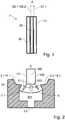
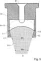
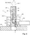
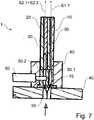
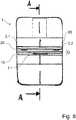
1 zeigt eine Seitenansicht einer Düsenvorrichtung gemäß einer Ausführungsform der Erfindung,2 zeigt eine Schnittansicht der in1 gezeigten ersten Düsenplatte,3 zeigt eine Schnittansicht der in1 gezeigten zweiten Düsenplatte,4 zeigt eine Schnittansicht der in1 gezeigten dritten Düsenplatte und illustriert einen mit der Düsenvorrichtung realisierbaren Applikationsprozess,5 zeigt eine Schnittansicht einer Düsenplatte gemäß einer anderen Ausführungsform der Erfindung,6 zeigt eine Schnittansicht einer Düsenvorrichtung gemäß einer Ausführungsform der Erfindung,7 zeigt eine Schnittansicht einer Düsenvorrichtung gemäß einer anderen Ausführungsform der Erfindung,8 zeigt eine Draufsicht auf die Düsenvorrichtung der7 ,9 zeigt eine Seitenansicht und eine zugehörige Draufsicht einer Düsenplatte gemäß einer anderen Ausführungsform der Erfindung,10 zeigt eine Seitenansicht und eine zugehörige Draufsicht einer Düsenplatte gemäß einer anderen Ausführungsform der Erfindung, und11 zeigt eine Seitenansicht und eine zugehörige Draufsicht einer Düsenplatte gemäß einer anderen Ausführungsform der Erfindung,12 zeigt eine Schnittansicht einer Düsenplatte gemäß einer anderen Ausführungsform der Erfindung,13 zeigt eine Schnittansicht einer Düsenplatte gemäß einer anderen Ausführungsform der Erfindung, und14 zeigt einen Applikationsprozess zur Abdichtung eines Stehfalzes gemäß Stand der Technik.
1 shows a side view of a nozzle device according to an embodiment of the invention,2 shows a sectional view of the in1 shown first nozzle plate,3 shows a sectional view of the in1 shown second nozzle plate,4 shows a sectional view of the in1 shown third nozzle plate and illustrates an implementable with the nozzle device application process,5 shows a sectional view of a nozzle plate according to another embodiment of the invention,6 shows a sectional view of a nozzle device according to an embodiment of the invention,7 shows a sectional view of a nozzle device according to another embodiment of the invention,8th shows a plan view of the nozzle device of7 .9 shows a side view and an associated plan view of a nozzle plate according to another embodiment of the invention,10 shows a side view and an associated plan view of a nozzle plate according to another embodiment of the invention, and11 shows a side view and an associated plan view of a nozzle plate according to another embodiment of the invention,12 shows a sectional view of a nozzle plate according to another embodiment of the invention,13 shows a sectional view of a nozzle plate according to another embodiment of the invention, and14 shows an application process for sealing a standing seam according to the prior art.
Die unter Bezugnahme auf die Figuren beschriebenen Ausführungsformen der Erfindung stimmen teilweise überein, wobei ähnliche oder identische Teile mit den gleichen Bezugszeichen versehen sind, und zu deren Erläuterung auch auf die Beschreibung anderer Ausführungsformen oder Figuren verwiesen wird, um Wiederholungen zu vermeiden.The embodiments of the invention described with reference to the figures are partly identical, with similar or identical parts being given the same reference numerals, and to the explanation of which reference is also made to the description of other embodiments or figures in order to avoid repetition.
Die Düsenvorrichtung
Die Düsenvorrichtung
Die Düsenvorrichtung
Die erste Düsenplatte
Die zweite Düsenplatte
Der Flachstrahl
Die zwei Öffnungen
Die zweite Düsenplatte
Eine dritte Düsenplatte
Ein Vergleich der
Beidseitig außen neben der Öffnung
Während der Abgabe des Abgabemediums können die Düsenvorrichtung
Der Strahl
Die Strahlen
Anwendungsfallabhängig und vorzugsweise ventilgesteuert kann das Abgabemedium aus der Öffnung
Die Düsenvorrichtung
Anwendungsfallabhängig und vorzugsweise ventilgesteuert kann das Abgabemedium aus den zwei Öffnungen
Anwendungsfallabhängig und vorzugsweise ventilgesteuert kann das Abgabemedium aus den zwei Öffnungen
Der Strahl
Eine Öffnungskonfiguration
Die Düsenplatte
Die Düsenvorrichtung
Die Düsenvorrichtung
Ein Ventil
Die Düsenvorrichtung
Das Sockelbauteil
Das Sockelbauteil
Das Sockelbauteil
Der erste Zufuhrabschnitt
Das Ventil
Eine z. B. zwei Klemmteile aufweisende Plattenhalterung
Das Ventil
Das Ventil
Die Düsenvorrichtung
Die Düsenvorrichtung
Eine Besonderheit ist aber, dass das Sockelbauteil
Das Ventil
Die zwei Öffnungen
Die Öffnung
Auch bei dieser Ausführungsform sind die zwei Öffnungen
Bei dieser Ausführungsform ist die Öffnungskonfiguration zur Ausbildung der Öffnung
Es ist möglich, dass die in den
So kann z. B. eine dritte Düsenplatte
Die Düsenplatte
Die zwei Strahlen
Die in
Die Düsenplatte
Eine Besonderheit ist aber, dass die Düsenplatte
Im Rahmen der Erfindung ist es möglich, die erste Düsenplatte zweckmäßig wie die zweite Düsenplatte auszubilden oder umgekehrt, so dass die Offenbarung hierin zur zweiten Düsenplatte zweckmäßig auch für die erste Düsenplatte gilt oder umgekehrt.In the context of the invention, it is possible to form the first nozzle plate expediently as the second nozzle plate or vice versa, so that the disclosure herein applies to the second nozzle plate expediently also for the first nozzle plate or vice versa.
Die Erfindung ist nicht auf die oben beschriebenen bevorzugten Ausführungsformen beschränkt. Vielmehr ist eine Vielzahl von Varianten und Abwandlungen möglich, die ebenfalls von dem Erfindungsgedanken Gebrauch machen und deshalb ebenfalls in den Schutzbereich fallen. Darüber hinaus beansprucht die Erfindung auch Schutz für den Gegenstand und die Merkmale der Unteransprüche unabhängig von den in Bezug genommenen Merkmalen und Ansprüchen.The invention is not limited to the preferred embodiments described above. Rather, a variety of variants and modifications is possible, which also make use of the idea of the invention and therefore also fall within the scope. Moreover, the invention also claims protection of the subject matter and the features of the subclaims independently of the features and claims referred to.
BezugszeichenlisteLIST OF REFERENCE NUMBERS
- 11
- Düsenvorrichtungnozzle device
- 1.11.1
- Öffnung, vorzugsweise SchlitzöffnungOpening, preferably slot opening
- 1.21.2
- Öffnung, vorzugsweise SchlitzöffnungOpening, preferably slot opening
- 2.12.1
- Öffnung, vorzugsweise SchlitzöffnungOpening, preferably slot opening
- 2.22.2
- Öffnung, vorzugsweise SchlitzöffnungOpening, preferably slot opening
- 2.32.3
- Öffnung, vorzugsweise SchlitzöffnungOpening, preferably slot opening
- 3.13.1
- Hornstrukturhorn structure
- 3.23.2
- Hornstrukturhorn structure
- 4.14.1
- Innenflankeinside edge
- 4.24.2
- Innenflankeinside edge
- 1010
- Düsenplattenozzle plate
- 2020
- Düsenplattenozzle plate
- 3030
- Düsenplattenozzle plate
- 4040
- Applikationskopf, z. B. 3D-Gun oder 3D-ApplikationskopfApplication head, z. B. 3D gun or 3D application head
- 5050
- Materialzufuhrmaterial supply
- 50.150.1
- Zufuhrabschnittfeeding section
- 50.250.2
- Zufuhrabschnittfeeding section
- 6060
- Ventil, vorzugsweise NadelventilValve, preferably needle valve
- 7070
- Sockelbauteil (Basisbauteil)Base component (base component)
- 8080
- Plattenhalterungdrive bracket
- S1.1S1.1
- Abgabestrahl, vorzugsweise FlachstrahlDispensing jet, preferably flat jet
- S1.2S1.2
- Abgabestrahl, vorzugsweise FlachstrahlDispensing jet, preferably flat jet
- S2.1S2.1
- Abgabestrahl, vorzugsweise FlachstrahlDispensing jet, preferably flat jet
- S2.2S2.2
- Abgabestrahl, vorzugsweise FlachstrahlDispensing jet, preferably flat jet
- S2.3S2.3
- Abgabestrahl, vorzugsweise FlachstrahlDispensing jet, preferably flat jet
- E1E1
- Eintrittsöffnunginlet opening
- E2E2
- Eintrittsöffnunginlet opening
- KK
- Öffnungskonfigurationopening configuration
- B1B1
- Strahlbreitebeamwidth
- B2B2
- Strahlbreitebeamwidth
- M1M1
- Materialzufuhrmaterial supply
- M2M2
- Materialzufuhrmaterial supply
- Querrichtungtransversely
- TT
- Teilungsabschnittdividing section
- 100100
- Bauteil, vorzugsweise KraftfahrzeugbauteilComponent, preferably motor vehicle component
- 101101
- Seitenflächeside surface
- 102102
- Seitenflächeside surface
- 103103
- Stirnflächeface
Claims (21)
Translated fromGermanPriority Applications (8)
| Application Number | Priority Date | Filing Date | Title |
|---|---|---|---|
| DE102016014269.3ADE102016014269A1 (en) | 2016-11-30 | 2016-11-30 | Nozzle device with at least two nozzle plates and at least three openings |
| EP17816557.7AEP3548191B1 (en) | 2016-11-30 | 2017-11-29 | Nozzle device having at least two nozzle plates and at least three openings |
| MX2019005991AMX2019005991A (en) | 2016-11-30 | 2017-11-29 | Nozzle device having at least two nozzle plates and at least three openings. |
| ES17816557TES2961945T3 (en) | 2016-11-30 | 2017-11-29 | Nozzle device with at least two nozzle plates and at least three openings |
| HUE17816557AHUE063588T2 (en) | 2016-11-30 | 2017-11-29 | Nozzle device having at least two nozzle plates and at least three openings |
| PCT/EP2017/080803WO2018099960A1 (en) | 2016-11-30 | 2017-11-29 | Nozzle device having at least two nozzle plates and at least three openings |
| US16/349,300US11583869B2 (en) | 2016-11-30 | 2017-11-29 | Nozzle device having at least two nozzle plates and at least three openings |
| CN201780074227.2ACN110022989B (en) | 2016-11-30 | 2017-11-29 | Nozzle arrangement with at least two nozzle plates and at least three openings |
Applications Claiming Priority (1)
| Application Number | Priority Date | Filing Date | Title |
|---|---|---|---|
| DE102016014269.3ADE102016014269A1 (en) | 2016-11-30 | 2016-11-30 | Nozzle device with at least two nozzle plates and at least three openings |
Publications (1)
| Publication Number | Publication Date |
|---|---|
| DE102016014269A1true DE102016014269A1 (en) | 2018-05-30 |
Family
ID=60702646
Family Applications (1)
| Application Number | Title | Priority Date | Filing Date |
|---|---|---|---|
| DE102016014269.3AWithdrawnDE102016014269A1 (en) | 2016-11-30 | 2016-11-30 | Nozzle device with at least two nozzle plates and at least three openings |
Country Status (8)
| Country | Link |
|---|---|
| US (1) | US11583869B2 (en) |
| EP (1) | EP3548191B1 (en) |
| CN (1) | CN110022989B (en) |
| DE (1) | DE102016014269A1 (en) |
| ES (1) | ES2961945T3 (en) |
| HU (1) | HUE063588T2 (en) |
| MX (1) | MX2019005991A (en) |
| WO (1) | WO2018099960A1 (en) |
Cited By (1)
| Publication number | Priority date | Publication date | Assignee | Title |
|---|---|---|---|---|
| DE102022119669A1 (en)* | 2022-08-04 | 2024-02-15 | Atlas Copco Ias Gmbh | Nozzle device for applying a viscous material |
Families Citing this family (1)
| Publication number | Priority date | Publication date | Assignee | Title |
|---|---|---|---|---|
| TWI852577B (en)* | 2023-05-23 | 2024-08-11 | 輝能科技股份有限公司 | Slot die coating apparatus and the coating method thereof |
Citations (1)
| Publication number | Priority date | Publication date | Assignee | Title |
|---|---|---|---|---|
| DE102013217686A1 (en)* | 2013-09-04 | 2015-03-05 | Heidelberger Druckmaschinen Ag | Device for printing on three-dimensional objects |
Family Cites Families (47)
| Publication number | Priority date | Publication date | Assignee | Title |
|---|---|---|---|---|
| US866163A (en) | 1906-10-15 | 1907-09-17 | Henry E Shaffer | Burner for acetylene gas. |
| US1186117A (en)* | 1915-02-25 | 1916-06-06 | James S Moe | Nozzle for painting apparatus. |
| US2284443A (en) | 1940-07-15 | 1942-05-26 | Raymond P Paradise | Blanket spray nozzle |
| US3615054A (en)* | 1965-09-24 | 1971-10-26 | Aerojet General Co | Injectors |
| BE757054R (en) | 1969-10-06 | 1971-04-05 | Monsanto Chemicals | IMPROVEMENTS WITH FOAMS |
| US5845846A (en) | 1969-12-17 | 1998-12-08 | Fujisaki Electric Co., Ltd. | Spraying nozzle and method for ejecting liquid as fine particles |
| GB2316022B (en) | 1996-02-16 | 2000-12-20 | Fujisaki Electric Co Ltd | Spraying nozzle and method for ejecting liquid as fine particles |
| US4195782A (en) | 1978-02-03 | 1980-04-01 | Rain Bird Sprinkler Mfg. Corp. | Method and device for enhancing the distribution of water from a sprinkler operated at low pressures |
| US4476165A (en)* | 1982-06-07 | 1984-10-09 | Acumeter Laboratories, Inc. | Method of and apparatus for multi-layer viscous fluid deposition such as for the application of adhesives and the like |
| US4567934A (en) | 1983-02-28 | 1986-02-04 | Kabushiki Kaisha Kobe Seiko Sho | Cooling mechanism for use in continuous metal casting |
| US4962891A (en)* | 1988-12-06 | 1990-10-16 | The Boc Group, Inc. | Apparatus for removing small particles from a substrate |
| US5088649A (en) | 1990-07-12 | 1992-02-18 | Par-Way Group | Pump sprayable dispensing system for vegetable oil based pan coatings |
| US5145689A (en)* | 1990-10-17 | 1992-09-08 | Exxon Chemical Patents Inc. | Meltblowing die |
| EP0579012B1 (en)* | 1992-07-08 | 1998-04-01 | Nordson Corporation | Apparatus and methods for applying discrete coatings |
| IL107120A (en) | 1992-09-29 | 1997-09-30 | Boehringer Ingelheim Int | Atomising nozzle and filter and spray generating device |
| US5503336A (en)* | 1994-07-14 | 1996-04-02 | United Air Specialists | High volume - low volume electrostatic dispensing nozzle assembly |
| ATE200325T1 (en)* | 1994-09-09 | 2001-04-15 | Voith Paper Patent Gmbh | APPLICATION WORK FOR THE DIRECT OR INDIRECT APPLICATION OF A LIQUID OR PASTY MEDIUM TO A RUNNING MATERIAL WEB |
| US5618566A (en)* | 1995-04-26 | 1997-04-08 | Exxon Chemical Patents, Inc. | Modular meltblowing die |
| GB9619260D0 (en) | 1995-11-01 | 1996-10-30 | Benest Eng Ltd | Agricultural and other spraying systems |
| US5904298A (en)* | 1996-10-08 | 1999-05-18 | Illinois Tool Works Inc. | Meltblowing method and system |
| US6680021B1 (en)* | 1996-07-16 | 2004-01-20 | Illinois Toolworks Inc. | Meltblowing method and system |
| DE29617525U1 (en) | 1996-10-11 | 1996-12-12 | Josef Schiele oHG, 56651 Niederzissen | Painting head |
| US6001178A (en)* | 1997-05-13 | 1999-12-14 | Nordson Corporation | Method and apparatus for applying uniform layers of adhesive to contoured surfaces of a substrate |
| JP2002512122A (en)* | 1998-04-17 | 2002-04-23 | ノードソン コーポレーション | Method and apparatus for applying a controlled pattern of fibrous material to a moving support |
| US6602554B1 (en) | 2000-01-14 | 2003-08-05 | Illinois Tool Works Inc. | Liquid atomization method and system |
| US6435425B1 (en)* | 2000-05-15 | 2002-08-20 | Nordson Corporation | Module and nozzle for dispensing controlled patterns of liquid material |
| US6375099B1 (en)* | 2000-06-21 | 2002-04-23 | Illinois Tool Works Inc. | Split output adhesive nozzle assembly |
| US7014131B2 (en) | 2002-06-20 | 2006-03-21 | Bowles Fluidics Corporation | Multiple spray devices for automotive and other applications |
| DE60319273T3 (en) | 2002-12-25 | 2014-03-13 | Kyoritsu Gokin Co., Ltd. | descaling |
| US20040155125A1 (en) | 2003-02-11 | 2004-08-12 | Kramer Martin S. | High pressure fluid jet nozzles and methods of making |
| JP2004283779A (en) | 2003-03-25 | 2004-10-14 | Hirata Corp | Liquid coating device and liquid coating method |
| US6817493B1 (en) | 2003-08-22 | 2004-11-16 | S. C. Johnson & Son, Inc. | Spray nozzle |
| DE102006012373B3 (en)* | 2006-03-17 | 2007-06-28 | Bayerische Motoren Werke Ag | Sound proof material application nozzle for motor vehicle, has outlet opening with two parallel slit-shaped openings of different lengths, where slit-shaped openings run parallel to one another |
| US7798434B2 (en)* | 2006-12-13 | 2010-09-21 | Nordson Corporation | Multi-plate nozzle and method for dispensing random pattern of adhesive filaments |
| GB0800709D0 (en) | 2008-01-16 | 2008-02-20 | Dunne Stephen T | Double jet impinging nozzle |
| US8074902B2 (en) | 2008-04-14 | 2011-12-13 | Nordson Corporation | Nozzle and method for dispensing random pattern of adhesive filaments |
| JP5676877B2 (en)* | 2009-12-28 | 2015-02-25 | ユニ・チャーム株式会社 | Nozzle device and diaper having a stretchable sheet manufactured using the same |
| DE202010002549U1 (en) | 2010-02-15 | 2010-11-18 | Schattat, Karl-Heinz, Dipl.-Ing. | Nozzles for applying glue / glue |
| US9138753B1 (en) | 2010-09-02 | 2015-09-22 | Hiroshi Takahara | Spray nozzle and the application |
| DE102011001597B4 (en) | 2011-03-28 | 2016-09-22 | Aluplast Gmbh | Adhesive nozzle with several outlet openings and method for introducing adhesive material |
| JP5830056B2 (en) | 2013-06-05 | 2015-12-09 | トヨタ自動車株式会社 | Press device and spray nozzle |
| US9643201B2 (en) | 2013-06-17 | 2017-05-09 | The Boeing Company | High viscosity fluid dispensing system |
| KR101503402B1 (en)* | 2013-07-12 | 2015-03-17 | 삼성디스플레이 주식회사 | Slit nozzle and method of manufacturing display device using the same |
| JP6319798B2 (en) | 2014-06-06 | 2018-05-09 | Necエナジーデバイス株式会社 | Coating apparatus and method for manufacturing secondary battery electrode |
| KR102231206B1 (en)* | 2014-07-18 | 2021-03-23 | 삼성디스플레이 주식회사 | Slot die coater and coating method using the same |
| DE102015200236A1 (en) | 2015-01-12 | 2016-07-14 | Lechler Gmbh | Method of producing a spray jet and two-fluid nozzle |
| CN106140563A (en) | 2016-07-22 | 2016-11-23 | 屠春山 | One can accurately adjust discharging uniform die head pad |
- 2016
- 2016-11-30DEDE102016014269.3Apatent/DE102016014269A1/ennot_activeWithdrawn
- 2017
- 2017-11-29EPEP17816557.7Apatent/EP3548191B1/enactiveActive
- 2017-11-29MXMX2019005991Apatent/MX2019005991A/enunknown
- 2017-11-29WOPCT/EP2017/080803patent/WO2018099960A1/ennot_activeCeased
- 2017-11-29CNCN201780074227.2Apatent/CN110022989B/enactiveActive
- 2017-11-29ESES17816557Tpatent/ES2961945T3/enactiveActive
- 2017-11-29HUHUE17816557Apatent/HUE063588T2/enunknown
- 2017-11-29USUS16/349,300patent/US11583869B2/enactiveActive
Patent Citations (1)
| Publication number | Priority date | Publication date | Assignee | Title |
|---|---|---|---|---|
| DE102013217686A1 (en)* | 2013-09-04 | 2015-03-05 | Heidelberger Druckmaschinen Ag | Device for printing on three-dimensional objects |
Cited By (1)
| Publication number | Priority date | Publication date | Assignee | Title |
|---|---|---|---|---|
| DE102022119669A1 (en)* | 2022-08-04 | 2024-02-15 | Atlas Copco Ias Gmbh | Nozzle device for applying a viscous material |
Also Published As
| Publication number | Publication date |
|---|---|
| EP3548191A1 (en) | 2019-10-09 |
| US11583869B2 (en) | 2023-02-21 |
| MX2019005991A (en) | 2019-07-08 |
| US20200179956A1 (en) | 2020-06-11 |
| WO2018099960A1 (en) | 2018-06-07 |
| CN110022989B (en) | 2022-05-31 |
| CN110022989A (en) | 2019-07-16 |
| EP3548191B1 (en) | 2023-08-16 |
| HUE063588T2 (en) | 2024-01-28 |
| ES2961945T3 (en) | 2024-03-14 |
Similar Documents
| Publication | Publication Date | Title |
|---|---|---|
| EP3548186B1 (en) | Nozzle device with concave opening configuration and method for dispensing a viscous application medium | |
| EP2678112B1 (en) | Nozzle head for applying an insulating material | |
| DE69926402T2 (en) | ABDICHTUNGSDÜSE | |
| EP3863895A1 (en) | Attachment for a wiper arm | |
| EP3548190B1 (en) | Nozzle device for dispensing two approaching jets of a medium to be dispensed | |
| EP3548191B1 (en) | Nozzle device having at least two nozzle plates and at least three openings | |
| EP3251762A1 (en) | Lubricating device for applying a lubricant when rolling a product to be rolled | |
| DE202015005290U1 (en) | nozzle assembly | |
| EP3205407B1 (en) | Method and installation for covering internal walls of a cavity with a protective layer made of corrosion protecting wax | |
| DE3709507A1 (en) | TIP PROTECTOR ON A SPRAY GUN | |
| DE19846073A1 (en) | Arrangement for flushing painting equipment, esp. for motor vehicle painting systems, has channel side matched to valve needle ends, which lie flush with surface of channel in closed state | |
| DE69400060T2 (en) | Flat jet nozzle, especially for high pressure cleaners | |
| DE2535587A1 (en) | Fluid applicator for moulded articles - has spray block with parallel channels between end blocks | |
| DE3312274A1 (en) | Spray head for the distribution of liquid or viscous materials within box-like metal profile parts | |
| WO2019043455A1 (en) | DEVICE FOR SPRAYING ADHESIVE AND PROCESSING | |
| DE102008036659A1 (en) | Device for applying coating on edge area of component, particularly sheet metal component, has application nozzle with U-shaped end area, where end area has exit slit for coating material | |
| DE1954813C3 (en) | Spray device, in particular spray gun | |
| DE102016011275B4 (en) | Device, modular system and method for applying liquid to pasty greasing agent to a workpiece surface | |
| WO2023046257A1 (en) | Method for discharging a liquid using a nozzle device | |
| EP0381052B1 (en) | Method and apparatus for spraying surfaces | |
| DE102012011352A1 (en) | Spray nozzle unit with at least two spray nozzles and coater with such a spray nozzle unit | |
| DE29708102U1 (en) | Device for applying adhesive | |
| DE102008017275B4 (en) | Moistening device of a spray dampening unit | |
| DE3732755C2 (en) | ||
| DE3206616C2 (en) | Process for lining pipes |
Legal Events
| Date | Code | Title | Description |
|---|---|---|---|
| R012 | Request for examination validly filed | ||
| R120 | Application withdrawn or ip right abandoned |