DE102016013740A1 - System for ventilating patients - Google Patents
System for ventilating patientsDownload PDFInfo
- Publication number
- DE102016013740A1 DE102016013740A1DE102016013740.1ADE102016013740ADE102016013740A1DE 102016013740 A1DE102016013740 A1DE 102016013740A1DE 102016013740 ADE102016013740 ADE 102016013740ADE 102016013740 A1DE102016013740 A1DE 102016013740A1
- Authority
- DE
- Germany
- Prior art keywords
- interface
- inlet port
- gas
- ventilating patients
- opening
- Prior art date
- Legal status (The legal status is an assumption and is not a legal conclusion. Google has not performed a legal analysis and makes no representation as to the accuracy of the status listed.)
- Pending
Links
Images


Classifications
- A—HUMAN NECESSITIES
- A61—MEDICAL OR VETERINARY SCIENCE; HYGIENE
- A61M—DEVICES FOR INTRODUCING MEDIA INTO, OR ONTO, THE BODY; DEVICES FOR TRANSDUCING BODY MEDIA OR FOR TAKING MEDIA FROM THE BODY; DEVICES FOR PRODUCING OR ENDING SLEEP OR STUPOR
- A61M16/00—Devices for influencing the respiratory system of patients by gas treatment, e.g. ventilators; Tracheal tubes
- A61M16/0057—Pumps therefor
- A61M16/0066—Blowers or centrifugal pumps
- A—HUMAN NECESSITIES
- A61—MEDICAL OR VETERINARY SCIENCE; HYGIENE
- A61M—DEVICES FOR INTRODUCING MEDIA INTO, OR ONTO, THE BODY; DEVICES FOR TRANSDUCING BODY MEDIA OR FOR TAKING MEDIA FROM THE BODY; DEVICES FOR PRODUCING OR ENDING SLEEP OR STUPOR
- A61M16/00—Devices for influencing the respiratory system of patients by gas treatment, e.g. ventilators; Tracheal tubes
- A61M16/10—Preparation of respiratory gases or vapours
- A61M16/12—Preparation of respiratory gases or vapours by mixing different gases
- A—HUMAN NECESSITIES
- A61—MEDICAL OR VETERINARY SCIENCE; HYGIENE
- A61M—DEVICES FOR INTRODUCING MEDIA INTO, OR ONTO, THE BODY; DEVICES FOR TRANSDUCING BODY MEDIA OR FOR TAKING MEDIA FROM THE BODY; DEVICES FOR PRODUCING OR ENDING SLEEP OR STUPOR
- A61M16/00—Devices for influencing the respiratory system of patients by gas treatment, e.g. ventilators; Tracheal tubes
- A61M16/0057—Pumps therefor
- A61M16/0063—Compressors
- A—HUMAN NECESSITIES
- A61—MEDICAL OR VETERINARY SCIENCE; HYGIENE
- A61M—DEVICES FOR INTRODUCING MEDIA INTO, OR ONTO, THE BODY; DEVICES FOR TRANSDUCING BODY MEDIA OR FOR TAKING MEDIA FROM THE BODY; DEVICES FOR PRODUCING OR ENDING SLEEP OR STUPOR
- A61M16/00—Devices for influencing the respiratory system of patients by gas treatment, e.g. ventilators; Tracheal tubes
- A61M16/021—Devices for influencing the respiratory system of patients by gas treatment, e.g. ventilators; Tracheal tubes operated by electrical means
- A61M16/022—Control means therefor
- A—HUMAN NECESSITIES
- A61—MEDICAL OR VETERINARY SCIENCE; HYGIENE
- A61M—DEVICES FOR INTRODUCING MEDIA INTO, OR ONTO, THE BODY; DEVICES FOR TRANSDUCING BODY MEDIA OR FOR TAKING MEDIA FROM THE BODY; DEVICES FOR PRODUCING OR ENDING SLEEP OR STUPOR
- A61M16/00—Devices for influencing the respiratory system of patients by gas treatment, e.g. ventilators; Tracheal tubes
- A61M16/08—Bellows; Connecting tubes ; Water traps; Patient circuits
- A61M16/0816—Joints or connectors
- A—HUMAN NECESSITIES
- A61—MEDICAL OR VETERINARY SCIENCE; HYGIENE
- A61M—DEVICES FOR INTRODUCING MEDIA INTO, OR ONTO, THE BODY; DEVICES FOR TRANSDUCING BODY MEDIA OR FOR TAKING MEDIA FROM THE BODY; DEVICES FOR PRODUCING OR ENDING SLEEP OR STUPOR
- A61M16/00—Devices for influencing the respiratory system of patients by gas treatment, e.g. ventilators; Tracheal tubes
- A61M16/10—Preparation of respiratory gases or vapours
- A61M16/1005—Preparation of respiratory gases or vapours with O2 features or with parameter measurement
- A—HUMAN NECESSITIES
- A61—MEDICAL OR VETERINARY SCIENCE; HYGIENE
- A61M—DEVICES FOR INTRODUCING MEDIA INTO, OR ONTO, THE BODY; DEVICES FOR TRANSDUCING BODY MEDIA OR FOR TAKING MEDIA FROM THE BODY; DEVICES FOR PRODUCING OR ENDING SLEEP OR STUPOR
- A61M16/00—Devices for influencing the respiratory system of patients by gas treatment, e.g. ventilators; Tracheal tubes
- A61M16/20—Valves specially adapted to medical respiratory devices
- A61M16/201—Controlled valves
- A—HUMAN NECESSITIES
- A61—MEDICAL OR VETERINARY SCIENCE; HYGIENE
- A61M—DEVICES FOR INTRODUCING MEDIA INTO, OR ONTO, THE BODY; DEVICES FOR TRANSDUCING BODY MEDIA OR FOR TAKING MEDIA FROM THE BODY; DEVICES FOR PRODUCING OR ENDING SLEEP OR STUPOR
- A61M16/00—Devices for influencing the respiratory system of patients by gas treatment, e.g. ventilators; Tracheal tubes
- A61M16/0003—Accessories therefor, e.g. sensors, vibrators, negative pressure
- A61M2016/0027—Accessories therefor, e.g. sensors, vibrators, negative pressure pressure meter
- A—HUMAN NECESSITIES
- A61—MEDICAL OR VETERINARY SCIENCE; HYGIENE
- A61M—DEVICES FOR INTRODUCING MEDIA INTO, OR ONTO, THE BODY; DEVICES FOR TRANSDUCING BODY MEDIA OR FOR TAKING MEDIA FROM THE BODY; DEVICES FOR PRODUCING OR ENDING SLEEP OR STUPOR
- A61M16/00—Devices for influencing the respiratory system of patients by gas treatment, e.g. ventilators; Tracheal tubes
- A61M16/0003—Accessories therefor, e.g. sensors, vibrators, negative pressure
- A61M2016/003—Accessories therefor, e.g. sensors, vibrators, negative pressure with a flowmeter
- A—HUMAN NECESSITIES
- A61—MEDICAL OR VETERINARY SCIENCE; HYGIENE
- A61M—DEVICES FOR INTRODUCING MEDIA INTO, OR ONTO, THE BODY; DEVICES FOR TRANSDUCING BODY MEDIA OR FOR TAKING MEDIA FROM THE BODY; DEVICES FOR PRODUCING OR ENDING SLEEP OR STUPOR
- A61M16/00—Devices for influencing the respiratory system of patients by gas treatment, e.g. ventilators; Tracheal tubes
- A61M16/10—Preparation of respiratory gases or vapours
- A61M16/1005—Preparation of respiratory gases or vapours with O2 features or with parameter measurement
- A61M2016/102—Measuring a parameter of the content of the delivered gas
- A—HUMAN NECESSITIES
- A61—MEDICAL OR VETERINARY SCIENCE; HYGIENE
- A61M—DEVICES FOR INTRODUCING MEDIA INTO, OR ONTO, THE BODY; DEVICES FOR TRANSDUCING BODY MEDIA OR FOR TAKING MEDIA FROM THE BODY; DEVICES FOR PRODUCING OR ENDING SLEEP OR STUPOR
- A61M2202/00—Special media to be introduced, removed or treated
- A61M2202/02—Gases
- A61M2202/0208—Oxygen
- A—HUMAN NECESSITIES
- A61—MEDICAL OR VETERINARY SCIENCE; HYGIENE
- A61M—DEVICES FOR INTRODUCING MEDIA INTO, OR ONTO, THE BODY; DEVICES FOR TRANSDUCING BODY MEDIA OR FOR TAKING MEDIA FROM THE BODY; DEVICES FOR PRODUCING OR ENDING SLEEP OR STUPOR
- A61M2205/00—General characteristics of the apparatus
- A61M2205/02—General characteristics of the apparatus characterised by a particular materials
- A61M2205/0272—Electro-active or magneto-active materials
- A61M2205/0294—Piezoelectric materials
Landscapes
- Health & Medical Sciences (AREA)
- Emergency Medicine (AREA)
- Pulmonology (AREA)
- Engineering & Computer Science (AREA)
- Anesthesiology (AREA)
- Biomedical Technology (AREA)
- Heart & Thoracic Surgery (AREA)
- Hematology (AREA)
- Life Sciences & Earth Sciences (AREA)
- Animal Behavior & Ethology (AREA)
- General Health & Medical Sciences (AREA)
- Public Health (AREA)
- Veterinary Medicine (AREA)
- Accommodation For Nursing Or Treatment Tables (AREA)
- Respiratory Apparatuses And Protective Means (AREA)
Abstract
Translated fromGerman
Description
Translated fromGermanDie Erfindung betrifft ein System zum Beatmen von Patienten, die eine Patientenschnittstelleneinheit zum Beatmen mit einer Schnittstellen-Einlassöffnung, ein Gasleitungselement, das fluidkommunizierend mit der Schnittstellen-Einlassöffnung verbunden ist, und eine Steuerungseinheit aufweist.The invention relates to a system for ventilating patients comprising a patient interface unit for breathing with an interface inlet port, a gas conduit member fluidly communicating with the interface inlet port, and a control unit.
Die Beatmung von Patienten wird in Krankenhäusern mit stationären und mobilen Geräten durchgeführt. Dabei kommt je nachdem, wie gut ein Patient selbst atmen kann oder nicht, ein stationäres Gerät oder ein mobiles Gerät zum Einsatz. Stationäre Geräte werden dabei für Patienten genutzt, die nicht mehr oder nur unter größten Schwierigkeiten selbst atmen können. Für Patienten, die nur eine leichte Unterstützung zum Atmen brauchen, werden mobile Geräte verwendet. Weiter werden mobile Beatmungsgeräte verwendet, um Patienten, die bislang stationär beatmet wurden, von den Beatmungsgeräten abzugewöhnen.Ventilation of patients is performed in hospitals with stationary and mobile devices. Depending on how well a patient can breathe or not, a stationary device or a mobile device is used. Stationary devices are used for patients who can no longer or only with great difficulty breathe themselves. For patients who only need light breathing support, mobile devices are used. Furthermore, mobile ventilators are used to wean patients who have been hospital-assisted ventilators from ventilators.
Stationäre Beatmungsgeräte umfassen Gasmischer, eine Druck- /Volumensteuerung, Sicherheitseinrichtungen, Energieversorgungseinrichtungen, eine Gesamtsteuerung, Monitoring-Einrichtungen und Bedienungsvorrichtungen. Sie sind komplex und schwer aufgebaut und sind nicht dazu geeignet, durch die Patienten mitgeführt zu werden. Die Beatmung erfolgt dabei über Einwegschläuche mit Durchmessern von ca. 18 mm und Masken. Exspirationsventile, die in Kontakt mit eventuell mit Keimen kontaminierter Ausatemluft gebracht wurden, werden entweder aufbereitet oder als Wegwerfartikel ausgeführt. Bei hoher Performance sind diese Geräte groß und teuer.Stationary ventilators include gas mixers, pressure / volume control, safety devices, power supplies, overall control, monitoring devices, and controls. They are complex and difficult to set up and are not designed to be carried by the patients. The respiration takes place via disposable tubes with diameters of approx. 18 mm and masks. Exhalation valves placed in contact with potentially exhaled air contaminated with germs are either treated or made disposable. At high performance, these devices are big and expensive.
Weiter sind CPAP (continuous positive airway pressure)-Geräte bekannt, die einen kontinuierlichen Druck bereitstellen. Außerdem sind Highflow-Systeme bekannt, die einen Blender/Gasmischer, Anfeuchter und eine Kanüle umfassen. Diese beiden Geräteklassen werden bei Patienten eingesetzt, die selbst atmen können und nur eine sehr geringe Beatmungsunterstützung benötigen. Nachteil dieser Geräteklassen ist, dass sie keine assistierte Unterstützung und keine mandatorischen Beatmungsmodi erlauben.Further, continuous positive airway pressure (CPAP) devices are known which provide continuous pressure. In addition, highflow systems are known, which include a blender / gas mixer, humidifier and a cannula. These two device classes are used in patients who can breathe on their own and only need very little ventilation support. Disadvantage of these device classes is that they do not allow assisted support and mandatory modes of ventilation.
Aufgabe der Erfindung ist es daher, eine Vorrichtung bzw. ein System bereitzustellen, das eine vollwertige Beatmung mit hoher Performance bereitstellt, wobei der gerätetechnische Aufwand minimal sein soll.The object of the invention is therefore to provide a device or a system that provides a full-blown ventilation with high performance, the device complexity should be minimal.
Die Aufgabe wird gelöst durch die Merkmale der unabhängigen Ansprüche. Vorteilhafte Weiterbildungen sind Gegenstand der abhängigen Ansprüche.The object is solved by the features of the independent claims. Advantageous developments are the subject of the dependent claims.
Erfindungsgemäß ist ein System zum Beatmen von Patienten vorgesehen, dass eine Gasdurchgangseinheit, die eine erste Einlassöffnung zum Anschließen einer Druckgasquelle und eine fluidkommunizierend mit der ersten Einlassöffnung verbundene Auslassöffnung aufweist, eine Patientenschnittstelleneinheit zum Beatmen, die eine Schnittstellen-Einlassöffnung umfasst, ein Gasleitungselement, das die Auslassöffnung mit der Schnittstellen-Einlassöffnung fluidkommunizierend verbindet, ein erstes steuerbares Druckänderungselement zwischen der ersten Einlassöffnung und der Schnittstellen-Einlassöffnung, eine zweite Einlassöffnung, die fluidkommunizierend mit dem Gasleitungselement verbunden ist, und eine Steuerungseinheit zum Steuern des steuerbaren Druckänderungselements umfasst.According to the invention, there is provided a system for ventilating patients in that a gas passage unit having a first inlet port for connecting a pressurized gas source and an outlet port fluidly communicating with the first inlet port, a patient interface unit for respiration that includes an interface inlet port, a gas conduit element that controls the Outlet opening fluidly communicating with the interface inlet port, a first controllable pressure change element between the first inlet port and the interface inlet port, a second inlet port, which is fluid communicating with the gas line element, and a control unit for controlling the controllable pressure change element comprises.
Durch das steuerbare Druckänderungselement zwischen der Gasdurchgangseinheit, die die erste Einlassöffnung aufweist, und der Patientenschnittstelleneinheit, die die Schnittstellen-Einlassöffnung aufweist, kann ein Druckunterschied zwischen der Gasdurchgangseinheit und der Patientenschnittstelleneinheit hergestellt werden. Auf diese Weise kann an der Gasdurchgangseinheit ein hoher Druck angelegt werden, wobei an der Patientenschnittstelleneinheit ein niedriger Druck angelegt ist. Dabei kann zum Beispiel eine Sauerstoffgasflasche oder eine Sauerstoffdruckversorgung mit der ersten Einlassöffnung verbunden werden. An der Gasdurchgangseinheit herrscht dann ein so hoher Druck, dass er zunächst für eine Einatmung durch einen Patienten nicht geeignet ist. Mittels des steuerbaren Druckänderungselementes wird dieser hohe Druck auf der Seite der Patientenschnittstelleneinheit so weit verringert, dass ein Patient, der durch die Patientenschnittstelleneinheit atmet, angenehm beatmet werden kann. Druckschwankungen auf Seiten der Gasdurchgangseinheit werden mittels des steuerbaren Druckänderungselementes ausgeglichen, sodass an der Patientenschnittstelleneinheit jeweils ein physiologisch sinnvoller Druck herrscht. Durch die Nutzung des Druckänderungselementes zwischen der Gasdurchgangseinheit und der Patientenschnittstelleneinheit kann damit eine beliebige Druckquelle für die Beatmung eines Patienten genutzt werden. So können zum Beispiel Wandversorgungseinheiten, die in dem ganzen Krankenhaus Druckluft bzw. unter Druck stehenden Sauerstoff bereitstellen, für die Beatmung des Patienten genutzt werden. Dabei kann eine assistierte bzw. mandatorische Beatmung erfolgen. Sogar Patienten, die eine große Unterstützung beim Atmen benötigen, können mittels der Erfindung mit hoher Performance und sicher beatmet werden.By the controllable pressure change element between the gas passage unit having the first inlet port and the patient interface unit having the interface inlet port, a pressure difference between the gas passage unit and the patient interface unit can be established. In this way, a high pressure can be applied to the gas passage unit, wherein a low pressure is applied to the patient interface unit. In this case, for example, an oxygen cylinder or an oxygen pressure supply can be connected to the first inlet opening. At the gas passage unit then prevails such a high pressure that it is initially not suitable for inhalation by a patient. By means of the controllable pressure change element, this high pressure on the side of the patient interface unit is reduced so far that a patient who breathes through the patient interface unit can be pleasantly ventilated. Pressure fluctuations on the part of the gas passage unit are compensated by means of the controllable pressure change element, so that in each case a physiologically sensible pressure prevails at the patient interface unit. By using the pressure change element between the gas passage unit and the patient interface unit can thus be used any pressure source for the ventilation of a patient. For example, wall supply units that provide compressed air or pressurized oxygen throughout the hospital can be used to ventilate the patient. This can be an assisted or mandatory ventilation. Even patients who require a great deal of breathing assistance can be ventilated with high performance and safety by means of the invention.
Weiter erlaubt die Erfindung, dass Patienten mobil mit dieser hohen Performance beatmet werden können, da bei einer Nutzung einer Druckluftflasche lediglich die Druckluftflasche mit dem Patientenbett mitgeführt werden muss. Im Gegensatz zum Stand der Technik ist es nun nicht mehr nötig, ein gesamtes, schweres Beatmungsgerät zu bewegen, das weiter eine kontinuierliche Stromversorgung benötigt. Im Gegensatz zu CPAP-Geräten bzw. Highflow-Geräten, sind nun auch Patienten mobil, die eine starke Unterstützung bei der Beatmung benötigen oder sogar mandatorisch beatmet werden müssen.Furthermore, the invention allows patients to be ventilated with this high performance on a mobile basis, since when using a compressed air cylinder only the compressed air cylinder with the patient bed has to be carried along. In contrast to It is no longer necessary, according to the prior art, to move an entire, heavy ventilator, which furthermore requires a continuous power supply. In contrast to CPAP devices or Highflow devices, patients are now also mobile, who need strong support in ventilation or even need mandatory ventilation.
Mittels der Erfindung wird damit bei einer hohen, vollwertigen Beatmungsperformance der gerätetechnische Aufwand minimal gehalten. Es lassen sich damit herkömmliche Gasquellen unabhängig von Beatmungsgeräten nutzen. Die Performance ist wie bei herkömmlichen Beatmungsgeräten, jedoch ist das erfindungsgemäße System kleiner, leichter, günstiger und einfacher zu bedienen.By means of the invention, the equipment complexity is thus kept to a minimum with a high, full-blown ventilation performance. This makes it possible to use conventional gas sources independently of respirators. The performance is the same as with conventional ventilators, but the system according to the invention is smaller, lighter, cheaper and easier to use.
Vorteilhafterweise ist das Druckänderungselement ein Feinregelventil. An dem Feinregelventil fällt dabei ein Druck zwischen der Gasdurchgangseinheit und der Patientenschnittstelleneinheit ab. Falls kein Gasfluss vorhanden ist, entfällt der Druckabfall am Feinregelventil, sodass an der Leitung zur Maske, d.h. zwischen dem Feinregelventil und der ersten Einlassöffnung, ein hoher Druck entsteht. Sobald wieder Gas in Richtung Maske fließen kann, wird der hohe Druck schnell abgebaut. Damit kann eine Patientengefährdung in einem einfachen Fehlerfall ausgeschlossen werden. Alternativ kann das steuerbare Druckänderungselement als schneller Druckminder ausgebildet sein.Advantageously, the pressure change element is a fine control valve. At the fine control valve thereby drops a pressure between the gas passage unit and the patient interface unit. If there is no gas flow, the pressure drop across the fine control valve is eliminated, so on the line to the mask, i. between the fine control valve and the first inlet opening, a high pressure arises. As soon as gas can flow again in the direction of the mask, the high pressure is rapidly reduced. Thus, a patient's risk in a simple error case can be excluded. Alternatively, the controllable pressure change element can be designed as a fast pressure reducer.
Mit Vorteil umfasst die Patientenschnittstelleneinheit eine Schnittstellen-Auslassöffnung, die ein steuerbares Gasauslassventil aufweist und die fluidkommunizierend mit der Schnittstellen-Einlassöffnung verbunden ist.Advantageously, the patient interface unit comprises an interface outlet port having a controllable gas outlet valve and being fluidly communicated with the interface inlet port.
Zweckmäßigerweise ist die zweite Einlassöffnung am Gasleitungselement angeordnet. Dabei kann die zweite Einlassöffnung als Venturi-Düse ausgebildet sein.Conveniently, the second inlet opening is arranged on the gas line element. In this case, the second inlet opening may be formed as a Venturi nozzle.
Mit Vorteil kann die zweite Einlassöffnung alternativ an der Gasdurchgangseinheit angeordnet sein. Damit kann eine zweite Hochdruckquelle an die Gasdurchgangseinheit angeschlossen werden. Wenn an der ersten und der zweiten Einlassöffnung verschiedene Gase oder Gasgemische eingeleitet werden, können die beiden Gase bzw. Gasgemische in der Gasdurchgangseinheit auf dem Weg zu der Auslassöffnung miteinander vermischt werden. Damit können physiologisch sinnvolle Gasgemische für den Patienten bereitgestellt werden.Advantageously, the second inlet opening may alternatively be arranged on the gas passage unit. Thus, a second high-pressure source can be connected to the gas passage unit. When various gases or gas mixtures are introduced at the first and second inlet openings, the two gases or gas mixtures in the gas passage unit can be mixed with one another on the way to the outlet opening. This physiologically useful gas mixtures can be provided for the patient.
Vorteilhafterweise ist ein zweites steuerbares Druckänderungselement zwischen der zweiten Einlassöffnung und der Schnittstellen-Einlassöffnung vorgesehen und fluidkommunizierend verbunden.Advantageously, a second controllable pressure change element is provided between the second inlet opening and the interface inlet opening and connected in a fluid-communicating manner.
Weiter kann es zweckmäßig sein, eine Anfeuchtvorrichtung zwischen der Auslassöffnung und der Schnittstellen-Einlassöffnung anzuordnen. Durch das Anordnen der Anfeuchtvorrichtung im Gaspfad zwischen der Auslassöffnung und der Schnittstellen-Einlassöffnung kann trockene Luft aus Gasflaschen bzw. aus Wandversorgungseinheiten befeuchtet werden. Weiter kann dem Patienten physiologisch sinnvoll aufbereitete Atemluft zugeführt werden. Die Anfeuchtvorrichtung ist vorzugweise mit dem Gasleitungselement verbunden.Furthermore, it may be expedient to arrange a moistening device between the outlet opening and the interface inlet opening. By arranging the moistening device in the gas path between the outlet opening and the interface inlet opening, dry air can be moistened from gas cylinders or from wall supply units. Furthermore, physiologically useful breathing air can be supplied to the patient. The moistening device is preferably connected to the gas line element.
Zwischen der Auslassöffnung und der Schnittstellen-Einlassöffnung kann mit Vorteil ein Gaskonzentrationssensor, vorzugsweise für Sauerstoff, angeordnet sein. Mit dem Gaskonzentrationssensor kann für bestimmte Gase, wie zum Beispiel Sauerstoff, eine Konzentration gemessen werden, die dann mittels der Steuerungseinheit und dem steuerbaren Druckänderungselement auf eine Konzentration eingestellt werden kann, die dem Patienten zugeführt werden soll.Between the outlet opening and the interface inlet opening, a gas concentration sensor, preferably for oxygen, can advantageously be arranged. With the gas concentration sensor for certain gases, such as oxygen, a concentration can be measured, which can then be adjusted by means of the control unit and the controllable pressure change element to a concentration to be supplied to the patient.
Weiter kann es zweckmäßig sein, einen Flusssensor zwischen der Auslassöffnung und der Schnittstellen-Einlassöffnung anzuordnen. Mit dem Flusssensor kann der Gasfluss zwischen der Auslassöffnung und der Schnittstellen-Einlassöffnung gemessen werden.Furthermore, it may be expedient to arrange a flow sensor between the outlet opening and the interface inlet opening. With the flow sensor, the gas flow between the outlet port and the interface inlet port can be measured.
Vorteilhafterweise ist die erste Einlassöffnung mit einer Sauerstoffdruckquelle verbunden. Weiter ist mit Vorteil die zweite Einlassöffnung mit einer Raumluftdruckquelle oder einer Raumluftquelle verbunden. Auf diese Weise kann Raumluft unter Druck mit Sauerstoff angereichert werden und dem Patienten zugeführt werden.Advantageously, the first inlet opening is connected to an oxygen pressure source. Furthermore, the second inlet opening is advantageously connected to a room air pressure source or a room air source. In this way, room air can be enriched under pressure with oxygen and fed to the patient.
Es zweckmäßig die Patientenschnittstelleneinheit als Maske, vorzugsweise als Nasenmaske, auszubilden. Auf diese Weise kann ein Patient bequem beatmet werden.It is expedient to design the patient interface unit as a mask, preferably as a nasal mask. In this way, a patient can be comfortably ventilated.
Weiter ist vorteilhafterweise eine Nutzerschnittstelle zum Bedienen der Steuerungseinheit vorgesehen, die über eine Signalverbindung mit der Steuerungseinheit verbunden sein kann. Die Signalverbindung kann dabei kabelgebunden oder kabellos erfolgen.Furthermore, a user interface for operating the control unit is advantageously provided, which may be connected to the control unit via a signal connection. The signal connection can be wired or wireless.
Mit Vorteil ist die Nutzerschnittstelle als Smartphone ausgebildet, auf der ein Steuerungsprogramm eine Eingabemaske für die einzustellenden Werte des Systems bereitstellt. Auf diese Weise kann auf einfache Weise eine Eingabemaske bereitgestellt werden, die von dem Personal oder auch von dem Patienten selbst unter Anleitung bedient werden kann. Anstatt eines Smartphones kann ein Tablet oder eine andere tragbare Recheneinheit als Nutzerschnittstelle verwendet werden. Ebenso kann ein einfacher Touchscreen als Nutzerschnittstelle verwendet werden.Advantageously, the user interface is designed as a smartphone, on which a control program provides an input mask for the values of the system to be set. In this way, an input mask can be provided in a simple manner, which can be operated by the staff or even by the patient himself under guidance. Instead of a smartphone, a tablet or other portable computing device can be used as a user interface. Likewise, a simple touchscreen can be used as a user interface.
Zweckmäßigerweise ist ein Drucksensor an dem Patientenschnittstellenelement angeordnet. Die steuerbaren Druckänderungselemente können in diesem Fall von der Steuerungseinheit auf Basis der Signale des Drucksensors geregelt. Auf diese Weise kann das System zum Beatmen unabhängig vom Eingangsdruck an den Einlassöffnungen betrieben werden.Conveniently, a pressure sensor is arranged on the patient interface element. The controllable pressure change elements can in this case be regulated by the control unit on the basis of the signals of the pressure sensor. In this way, the system can be operated to ventilate regardless of the inlet pressure at the inlet openings.
Mit Vorteil kann das Gasleitungselement weiter einen freien Durchmesser zwischen 5 mm und 15 mm, vorzugsweise 10 mm, aufweisen. Durch die Regelung des Drucks mittels des Druckänderungselements kann ein Druckabfall, der durch den Durchmesser des Gasleitungselements zwischen der Auslassöffnung und der Schnittstellen-Einlassöffnung bewirkt wird, durch einen entsprechend höheren Druck an der Auslassöffnung ausgeglichen werden. Der Durchmesser des Gasleitungselements kann daher flexibel, insbesondere kleiner als im Stand der Technik, gewählt werden. Dadurch können dünnere Gasleitungselemente als im Stand der Technik genutzt werden, die flexibel und leicht sind. Einem Patienten wird die Mobilität durch die flexibleren, dünneren und damit leichteren Gasleitungen erleichtert.Advantageously, the gas line element further has a free diameter between 5 mm and 15 mm, preferably 10 mm. By controlling the pressure by means of the pressure change element, a pressure drop, which is caused by the diameter of the gas line element between the outlet opening and the interface inlet opening, can be compensated by a correspondingly higher pressure at the outlet opening. The diameter of the gas line element can therefore be chosen flexibly, in particular smaller than in the prior art. As a result, thinner gas line elements than in the prior art can be used, which are flexible and lightweight. A patient is facilitated mobility through the more flexible, thinner and therefore lighter gas lines.
Die Erfindung wird im Folgenden anhand der beigefügten Zeichnungen mittels eines vorteilhaften Ausführungsbeispiels näher erläutert. Es zeigen:
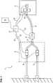
1 : eine schematische Darstellung eines Systems zum Beatmen, das an zwei Wandversorgungsgasquellen angeschlossen ist;2 : eine schematische Darstellung eines Systems zum Beatmen mit einem Wandanschluss und einer Venturi-Düse; und3 : eine schematische Darstellung eines steuerbaren Exspirationsventils.
1 Fig. 1 is a schematic illustration of a system for breathing connected to two wall supply gas sources;2 a schematic representation of a system for breathing with a wall connection and a venturi nozzle; and3 : a schematic representation of a controllable expiratory valve.
Im Folgenden wird das System zum Beatmen in seiner Gesamtheit mit dem Referenzzeichen
Das System
Die Gasdurchgangseinheit
Weiter ist zwischen der zweiten Einlassöffnung
An die erste und zweite Einlassöffnung
Durch die steuerbaren Druckänderungselemente
Weiter kann mittels der steuerbaren Druckänderungselemente
Die Schnittstelle zum Patienten wird über die Patientenschnittstelleneinheit
Weiter umfasst die Patientenschnittstelleneinheit
Es weist gemäß
Der Antrieb
Die Pumpöffnung
Das System
Die Steuerungseinheit
Eine als Smartphone oder Tablet ausgebildete Nutzerschnittstelle
Weiter wird einem Patienten ermöglicht, Feinjustierungen mittels der Nutzerschnittstelle
Das Gasleitungselement
Weiter umfasst das Gasleitungselement
Das Gasleitungselement
Dabei ist weiter ein Drucksensor
Die Steuerungseinheit
In
An die Auslassöffnung
Das Gasleitungselement
Die Patientenschnittstelleneinheit
Weiter umfasst die Gasdurchgangseinheit
Weiter wird das Signal des Flusssensors
Auf diese Weise kann mittels einer kostengünstigen Hochdruckquelle eine vollwertige Beatmung mit hoher Performance für einen zu beatmenden Patienten durchgeführt werden.In this way, by means of a low-cost high-pressure source, full-quality ventilation with high performance for a patient to be ventilated can be performed.
BezugszeichenlisteLIST OF REFERENCE NUMBERS
- 11
- Systemsystem
- 22
- GasdurchgangseinheitGas passage unit
- 33
- PatientenschnittstelleneinheitPatient interface unit
- 44
- GasleitungselementGas line element
- 55
- erstes steuerbares Druckänderungselementfirst controllable pressure change element
- 66
- erste Einlassöffnungfirst inlet opening
- 77
- Steuerungseinheitcontrol unit
- 88th
- zweite Einlassöffnungsecond inlet opening
- 99
- Auslassöffnungoutlet
- 1010
- Schnittstellen-EinlassöffnungInterfaces inlet port
- 1111
- zweites steuerbares Druckänderungselementsecond controllable pressure change element
- 1212
- SauerstoffdruckquelleOxygen pressure source
- 1313
- LuftdruckquelleAir pressure source
- 1414
- Maskemask
- 1515
- Exspirationsventilexpiratory
- 1616
- NutzerschnittstelleUser interface
- 1717
- EnergiequellenelementEnergy source element
- 1818
- GaskonzentrationssensorGas concentration sensor
- 1919
- Flusssensorflow sensor
- 2020
- Anzeigeelementdisplay element
- 2121
- AnfeuchtmodulAnfeuchtmodul
- 2222
- Signalverbindungsignal connection
- 2323
- Drucksensorpressure sensor
- 2424
- Antriebdrive
- 2525
- Membranmembrane
- 2626
- Pumpenkammerpump chamber
- 2727
- Pumpöffnungpumping port
- 2828
- erste Endöffnungfirst end opening
- 2929
- zweite Endöffnungsecond end opening
- 3030
- SteuerdruckkammerControl pressure chamber
- 3131
- Pumpleitungpumping line
- 3232
- Ventilöffnungvalve opening
Claims (15)
Translated fromGermanPriority Applications (3)
| Application Number | Priority Date | Filing Date | Title |
|---|---|---|---|
| DE102016013740.1ADE102016013740A1 (en) | 2016-11-17 | 2016-11-17 | System for ventilating patients |
| US15/814,812US10898665B2 (en) | 2016-11-17 | 2017-11-16 | System for ventilating patients |
| JP2017220646AJP6707508B2 (en) | 2016-11-17 | 2017-11-16 | System to give artificial respiration to patient |
Applications Claiming Priority (1)
| Application Number | Priority Date | Filing Date | Title |
|---|---|---|---|
| DE102016013740.1ADE102016013740A1 (en) | 2016-11-17 | 2016-11-17 | System for ventilating patients |
Publications (1)
| Publication Number | Publication Date |
|---|---|
| DE102016013740A1true DE102016013740A1 (en) | 2018-05-17 |
Family
ID=62026125
Family Applications (1)
| Application Number | Title | Priority Date | Filing Date |
|---|---|---|---|
| DE102016013740.1APendingDE102016013740A1 (en) | 2016-11-17 | 2016-11-17 | System for ventilating patients |
Country Status (3)
| Country | Link |
|---|---|
| US (1) | US10898665B2 (en) |
| JP (1) | JP6707508B2 (en) |
| DE (1) | DE102016013740A1 (en) |
Families Citing this family (5)
| Publication number | Priority date | Publication date | Assignee | Title |
|---|---|---|---|---|
| DE102019003643A1 (en)* | 2019-05-24 | 2020-11-26 | Drägerwerk AG & Co. KGaA | Arrangement with an inspiration valve for a ventilation system |
| CN114450053A (en)* | 2019-09-10 | 2022-05-06 | 费雪派克医疗保健有限公司 | Methods and systems for controlling oxygen delivery in flow therapy devices |
| US12292429B2 (en) | 2020-06-29 | 2025-05-06 | Dräger Safety AG & Co. KGaA | Monitoring system |
| DE102021111431A1 (en) | 2020-06-29 | 2021-12-30 | Dräger Safety AG & Co. KGaA | Surveillance system |
| DE102023113215A1 (en)* | 2023-05-19 | 2024-11-21 | Egor Egorov | Hypoxia device and method for conducting hypoxia training |
Citations (1)
| Publication number | Priority date | Publication date | Assignee | Title |
|---|---|---|---|---|
| DE102012024672A1 (en)* | 2012-12-18 | 2014-06-18 | Dräger Medical GmbH | Respirator and method of operating a ventilator |
Family Cites Families (29)
| Publication number | Priority date | Publication date | Assignee | Title |
|---|---|---|---|---|
| US3840006A (en)* | 1973-04-26 | 1974-10-08 | Department Of Health Education | Respirator |
| JPS5854963A (en)* | 1981-09-25 | 1983-04-01 | 株式会社アイカ | Fighting preventing apparatus in artificial respirator |
| DE3822949A1 (en)* | 1988-07-07 | 1990-01-11 | Draegerwerk Ag | PNEUMATIC CONTROL VALVE |
| JP2000014784A (en) | 1998-07-02 | 2000-01-18 | Instrumentarium Oy | Auxiliary respiration ventilator and safety valve of patient conduit of auxiliary respiration apparatus |
| AU2506300A (en)* | 1999-02-04 | 2000-08-25 | Versamed Medical Systems Ltd. | Computer-controlled portable ventilator |
| JP2004298554A (en) | 2003-04-01 | 2004-10-28 | Teijin Ltd | Respiratory gas supplying device |
| US7484940B2 (en)* | 2004-04-28 | 2009-02-03 | Kinetic Ceramics, Inc. | Piezoelectric fluid pump |
| ITMI20060158U1 (en) | 2006-05-04 | 2007-11-05 | Starmed S P A | EQUIPMENT FOR THE ADMINISTRATION OF OXYGEN OR AIR ADDED BY OXYGEN, FOR RESPIRATORY THERAPIES. |
| DE102008028733B4 (en)* | 2008-06-17 | 2016-02-04 | Drägerwerk AG & Co. KGaA | Device for determining a flow state in a breathing system |
| WO2011070471A1 (en) | 2009-12-07 | 2011-06-16 | Koninklijke Philips Electronics N.V. | Modular ventilation system |
| JP5417561B2 (en)* | 2011-09-12 | 2014-02-19 | 株式会社メトラン | Expiratory valve and respiratory assistance device |
| JP5286476B2 (en)* | 2011-12-08 | 2013-09-11 | 株式会社メトラン | Pump unit, breathing assistance device |
| EP2804654A4 (en)* | 2012-02-15 | 2015-08-26 | Fisher & Paykel Healthcare Ltd | System, apparatus and methods for supplying gases |
| JP5636555B2 (en)* | 2012-04-02 | 2014-12-10 | 株式会社メトラン | Pump unit, breathing assistance device |
| JP6240823B2 (en)* | 2012-04-16 | 2017-12-06 | 株式会社メトラン | Opening and closing device and respiratory assistance device |
| WO2013175345A1 (en)* | 2012-05-22 | 2013-11-28 | Koninklijke Philips N.V. | Cough assistance and measurement system and method cross-reference to related applications |
| US9669172B2 (en)* | 2012-07-05 | 2017-06-06 | Resmed Limited | Discreet respiratory therapy system |
| WO2014057457A2 (en)* | 2012-10-10 | 2014-04-17 | Koninklijke Philips N.V. | Adaptive patient circuit compensation with pressure sensor at mask apparatus |
| US10149954B2 (en)* | 2013-03-14 | 2018-12-11 | Resmed Limited | Device for providing breathable gas |
| JP6273420B2 (en) | 2013-03-18 | 2018-02-07 | 株式会社メトラン | Expiratory valve and respiratory assistance device |
| DE102013006545B4 (en)* | 2013-04-16 | 2020-02-27 | Dräger Safety AG & Co. KGaA | Measuring device and measuring method for a reaction carrier |
| JP2015073830A (en)* | 2013-10-11 | 2015-04-20 | 株式会社メトラン | Opening/closing implement and respiration auxiliary device |
| SG2013097191A (en)* | 2013-12-04 | 2015-07-30 | Innosparks Pte Ltd | Respiratory device with active venting system |
| US10344753B2 (en)* | 2014-02-28 | 2019-07-09 | Encite Llc | Micro pump systems |
| JP6326569B2 (en)* | 2014-03-26 | 2018-05-23 | 株式会社メトラン | Respiratory device |
| DE102014109394A1 (en)* | 2014-07-04 | 2016-01-07 | Ms Westfalia Gmbh | breathing device |
| US20160287824A1 (en)* | 2015-04-03 | 2016-10-06 | Invent Medical Corporation | Ventilator |
| US10695522B2 (en)* | 2016-03-14 | 2020-06-30 | ResMed Pty Ltd | Respiratory pressure therapy device |
| US10773045B2 (en)* | 2016-09-30 | 2020-09-15 | Kirura Holding B.V. | Anesthesia delivery and ventilation system |
- 2016
- 2016-11-17DEDE102016013740.1Apatent/DE102016013740A1/enactivePending
- 2017
- 2017-11-16USUS15/814,812patent/US10898665B2/enactiveActive
- 2017-11-16JPJP2017220646Apatent/JP6707508B2/enactiveActive
Patent Citations (1)
| Publication number | Priority date | Publication date | Assignee | Title |
|---|---|---|---|---|
| DE102012024672A1 (en)* | 2012-12-18 | 2014-06-18 | Dräger Medical GmbH | Respirator and method of operating a ventilator |
Also Published As
| Publication number | Publication date |
|---|---|
| US20180133420A1 (en) | 2018-05-17 |
| JP2018079325A (en) | 2018-05-24 |
| US10898665B2 (en) | 2021-01-26 |
| JP6707508B2 (en) | 2020-06-10 |
Similar Documents
| Publication | Publication Date | Title |
|---|---|---|
| DE102007019487B3 (en) | Modular breathing system for patient, has stationary parts detachably attaching breathing module, and detachable connection interface for data, electrical energy and inhaled gas attached to stationary parts receiving module | |
| EP3164183B1 (en) | Respiratory device | |
| DE69513042T2 (en) | VENTILATOR | |
| DE102016013740A1 (en) | System for ventilating patients | |
| DE69822886T2 (en) | PISTON VENTILATOR WITH OXYGEN MIXTURE | |
| DE69635451T2 (en) | BY MICROPROCESSOR HYBRID-CONTROLLED VENTILATION UNIT | |
| DE69930183T2 (en) | anesthesia machine | |
| EP3815729A1 (en) | Anesthesia machine and system | |
| DE69729416T2 (en) | anesthesia systems | |
| DE2801546A1 (en) | VENTILATION DEVICE ESPECIALLY FOR SMALL CHILDREN | |
| EP3536369B1 (en) | Respiratory apparatus with switching valve | |
| JP2004290673A (en) | Portable assembly for emergency ventilation | |
| DE102016122187A1 (en) | High-frequency generator for ventilation and procedures | |
| DE202015105799U1 (en) | oxygen mask | |
| DE102004011907B4 (en) | Anesthesia ventilator | |
| DE60028532T2 (en) | Device for high-frequency mechanical ventilation | |
| DE102006032498B3 (en) | Respirator, e.g. combined narcosis- and/or therapy respirator, for therapeutic and operational application, has fresh mixture decoupling valve coupled with hybrid point and corresponding to reversing valve by control- and regulating device | |
| EP4197580B1 (en) | Arrangement for supplying a patient-side coupling unit with a gas mixture | |
| EP4197581B1 (en) | Arrangement for supplying a patient-side coupling unit with a gas mixture | |
| EP3218039B1 (en) | Multifunctional applicator which can be used in a mobile manner | |
| EP3936177B1 (en) | Breathing apparatus | |
| DE19708094C2 (en) | Ventilator and method for operating a respirator | |
| DE102007058807A1 (en) | Device for providing respiratory gas mixture consisting of at least two gases has facility for recording volumetric flow and/or mass flow, or of gas composition, of at least one gas or gas mixture to be mixed | |
| DE102005039220B3 (en) | Breathing apparatus, used for patient during operation, comprises hand breathing bag with actuating sensor connected to inspiratory line via connecting line | |
| DE102013017348B3 (en) | Multifunctional, mobile applicator |
Legal Events
| Date | Code | Title | Description |
|---|---|---|---|
| R163 | Identified publications notified | ||
| R012 | Request for examination validly filed | ||
| R016 | Response to examination communication |