DE102016002225A1 - Process and apparatus for cryogenic synthesis gas separation - Google Patents
Process and apparatus for cryogenic synthesis gas separationDownload PDFInfo
- Publication number
- DE102016002225A1 DE102016002225A1DE102016002225.6ADE102016002225ADE102016002225A1DE 102016002225 A1DE102016002225 A1DE 102016002225A1DE 102016002225 ADE102016002225 ADE 102016002225ADE 102016002225 A1DE102016002225 A1DE 102016002225A1
- Authority
- DE
- Germany
- Prior art keywords
- separation column
- feed gas
- carbon monoxide
- column
- reboiler
- Prior art date
- Legal status (The legal status is an assumption and is not a legal conclusion. Google has not performed a legal analysis and makes no representation as to the accuracy of the status listed.)
- Withdrawn
Links
- 238000000926separation methodMethods0.000titleclaimsabstractdescription97
- 238000000034methodMethods0.000titleclaimsabstractdescription37
- 230000015572biosynthetic processEffects0.000titledescription2
- 238000003786synthesis reactionMethods0.000titledescription2
- 239000007789gasSubstances0.000claimsabstractdescription72
- UGFAIRIUMAVXCW-UHFFFAOYSA-NCarbon monoxideChemical compound[O+]#[C-]UGFAIRIUMAVXCW-UHFFFAOYSA-N0.000claimsabstractdescription55
- 229910002091carbon monoxideInorganic materials0.000claimsabstractdescription55
- VNWKTOKETHGBQD-UHFFFAOYSA-NmethaneChemical compoundCVNWKTOKETHGBQD-UHFFFAOYSA-N0.000claimsabstractdescription45
- 239000007791liquid phaseSubstances0.000claimsabstractdescription37
- 238000001816coolingMethods0.000claimsabstractdescription32
- 238000010438heat treatmentMethods0.000claimsabstractdescription25
- 239000003507refrigerantSubstances0.000claimsabstractdescription23
- 239000001257hydrogenSubstances0.000claimsabstractdescription19
- 229910052739hydrogenInorganic materials0.000claimsabstractdescription19
- UFHFLCQGNIYNRP-UHFFFAOYSA-NHydrogenChemical compound[H][H]UFHFLCQGNIYNRP-UHFFFAOYSA-N0.000claimsabstractdescription14
- 239000012071phaseSubstances0.000claimsabstractdescription12
- 150000002431hydrogenChemical class0.000claimsabstractdescription5
- 239000007788liquidSubstances0.000claimsdescription24
- 238000010992refluxMethods0.000claimsdescription12
- 238000001704evaporationMethods0.000claimsdescription11
- 230000008020evaporationEffects0.000claimsdescription11
- 238000009833condensationMethods0.000claimsdescription8
- 230000005494condensationEffects0.000claimsdescription8
- 239000012808vapor phaseSubstances0.000claimsdescription7
- 238000005057refrigerationMethods0.000claimsdescription6
- 238000000354decomposition reactionMethods0.000claimsdescription3
- IJGRMHOSHXDMSA-UHFFFAOYSA-NAtomic nitrogenChemical compoundN#NIJGRMHOSHXDMSA-UHFFFAOYSA-N0.000description30
- 229910052757nitrogenInorganic materials0.000description15
- 239000002737fuel gasSubstances0.000description6
- 239000000203mixtureSubstances0.000description5
- 238000005265energy consumptionMethods0.000description2
- 238000004172nitrogen cycleMethods0.000description2
- 238000010792warmingMethods0.000description2
- LYCAIKOWRPUZTN-UHFFFAOYSA-NEthylene glycolChemical compoundOCCOLYCAIKOWRPUZTN-UHFFFAOYSA-N0.000description1
- 239000003990capacitorSubstances0.000description1
- 238000006243chemical reactionMethods0.000description1
- 238000005056compactionMethods0.000description1
- 239000002826coolantSubstances0.000description1
- 238000004821distillationMethods0.000description1
- 238000000605extractionMethods0.000description1
- 230000003647oxidationEffects0.000description1
- 238000007254oxidation reactionMethods0.000description1
- 230000008092positive effectEffects0.000description1
- 238000000746purificationMethods0.000description1
- 238000004064recyclingMethods0.000description1
- 239000000126substanceSubstances0.000description1
- 238000011144upstream manufacturingMethods0.000description1
- 238000009834vaporizationMethods0.000description1
- 230000008016vaporizationEffects0.000description1
- XLYOFNOQVPJJNP-UHFFFAOYSA-NwaterSubstancesOXLYOFNOQVPJJNP-UHFFFAOYSA-N0.000description1
Images

Classifications
- F—MECHANICAL ENGINEERING; LIGHTING; HEATING; WEAPONS; BLASTING
- F25—REFRIGERATION OR COOLING; COMBINED HEATING AND REFRIGERATION SYSTEMS; HEAT PUMP SYSTEMS; MANUFACTURE OR STORAGE OF ICE; LIQUEFACTION SOLIDIFICATION OF GASES
- F25J—LIQUEFACTION, SOLIDIFICATION OR SEPARATION OF GASES OR GASEOUS OR LIQUEFIED GASEOUS MIXTURES BY PRESSURE AND COLD TREATMENT OR BY BRINGING THEM INTO THE SUPERCRITICAL STATE
- F25J3/00—Processes or apparatus for separating the constituents of gaseous or liquefied gaseous mixtures involving the use of liquefaction or solidification
- F25J3/02—Processes or apparatus for separating the constituents of gaseous or liquefied gaseous mixtures involving the use of liquefaction or solidification by rectification, i.e. by continuous interchange of heat and material between a vapour stream and a liquid stream
- F25J3/0204—Processes or apparatus for separating the constituents of gaseous or liquefied gaseous mixtures involving the use of liquefaction or solidification by rectification, i.e. by continuous interchange of heat and material between a vapour stream and a liquid stream characterised by the feed stream
- F25J3/0223—H2/CO mixtures, i.e. synthesis gas; Water gas or shifted synthesis gas
- F—MECHANICAL ENGINEERING; LIGHTING; HEATING; WEAPONS; BLASTING
- F25—REFRIGERATION OR COOLING; COMBINED HEATING AND REFRIGERATION SYSTEMS; HEAT PUMP SYSTEMS; MANUFACTURE OR STORAGE OF ICE; LIQUEFACTION SOLIDIFICATION OF GASES
- F25J—LIQUEFACTION, SOLIDIFICATION OR SEPARATION OF GASES OR GASEOUS OR LIQUEFIED GASEOUS MIXTURES BY PRESSURE AND COLD TREATMENT OR BY BRINGING THEM INTO THE SUPERCRITICAL STATE
- F25J3/00—Processes or apparatus for separating the constituents of gaseous or liquefied gaseous mixtures involving the use of liquefaction or solidification
- F25J3/02—Processes or apparatus for separating the constituents of gaseous or liquefied gaseous mixtures involving the use of liquefaction or solidification by rectification, i.e. by continuous interchange of heat and material between a vapour stream and a liquid stream
- F25J3/0228—Processes or apparatus for separating the constituents of gaseous or liquefied gaseous mixtures involving the use of liquefaction or solidification by rectification, i.e. by continuous interchange of heat and material between a vapour stream and a liquid stream characterised by the separated product stream
- F25J3/0233—Processes or apparatus for separating the constituents of gaseous or liquefied gaseous mixtures involving the use of liquefaction or solidification by rectification, i.e. by continuous interchange of heat and material between a vapour stream and a liquid stream characterised by the separated product stream separation of CnHm with 1 carbon atom or more
- F—MECHANICAL ENGINEERING; LIGHTING; HEATING; WEAPONS; BLASTING
- F25—REFRIGERATION OR COOLING; COMBINED HEATING AND REFRIGERATION SYSTEMS; HEAT PUMP SYSTEMS; MANUFACTURE OR STORAGE OF ICE; LIQUEFACTION SOLIDIFICATION OF GASES
- F25J—LIQUEFACTION, SOLIDIFICATION OR SEPARATION OF GASES OR GASEOUS OR LIQUEFIED GASEOUS MIXTURES BY PRESSURE AND COLD TREATMENT OR BY BRINGING THEM INTO THE SUPERCRITICAL STATE
- F25J3/00—Processes or apparatus for separating the constituents of gaseous or liquefied gaseous mixtures involving the use of liquefaction or solidification
- F25J3/02—Processes or apparatus for separating the constituents of gaseous or liquefied gaseous mixtures involving the use of liquefaction or solidification by rectification, i.e. by continuous interchange of heat and material between a vapour stream and a liquid stream
- F25J3/0228—Processes or apparatus for separating the constituents of gaseous or liquefied gaseous mixtures involving the use of liquefaction or solidification by rectification, i.e. by continuous interchange of heat and material between a vapour stream and a liquid stream characterised by the separated product stream
- F25J3/0252—Processes or apparatus for separating the constituents of gaseous or liquefied gaseous mixtures involving the use of liquefaction or solidification by rectification, i.e. by continuous interchange of heat and material between a vapour stream and a liquid stream characterised by the separated product stream separation of hydrogen
- F—MECHANICAL ENGINEERING; LIGHTING; HEATING; WEAPONS; BLASTING
- F25—REFRIGERATION OR COOLING; COMBINED HEATING AND REFRIGERATION SYSTEMS; HEAT PUMP SYSTEMS; MANUFACTURE OR STORAGE OF ICE; LIQUEFACTION SOLIDIFICATION OF GASES
- F25J—LIQUEFACTION, SOLIDIFICATION OR SEPARATION OF GASES OR GASEOUS OR LIQUEFIED GASEOUS MIXTURES BY PRESSURE AND COLD TREATMENT OR BY BRINGING THEM INTO THE SUPERCRITICAL STATE
- F25J3/00—Processes or apparatus for separating the constituents of gaseous or liquefied gaseous mixtures involving the use of liquefaction or solidification
- F25J3/02—Processes or apparatus for separating the constituents of gaseous or liquefied gaseous mixtures involving the use of liquefaction or solidification by rectification, i.e. by continuous interchange of heat and material between a vapour stream and a liquid stream
- F25J3/0228—Processes or apparatus for separating the constituents of gaseous or liquefied gaseous mixtures involving the use of liquefaction or solidification by rectification, i.e. by continuous interchange of heat and material between a vapour stream and a liquid stream characterised by the separated product stream
- F25J3/0261—Processes or apparatus for separating the constituents of gaseous or liquefied gaseous mixtures involving the use of liquefaction or solidification by rectification, i.e. by continuous interchange of heat and material between a vapour stream and a liquid stream characterised by the separated product stream separation of carbon monoxide
- F—MECHANICAL ENGINEERING; LIGHTING; HEATING; WEAPONS; BLASTING
- F25—REFRIGERATION OR COOLING; COMBINED HEATING AND REFRIGERATION SYSTEMS; HEAT PUMP SYSTEMS; MANUFACTURE OR STORAGE OF ICE; LIQUEFACTION SOLIDIFICATION OF GASES
- F25J—LIQUEFACTION, SOLIDIFICATION OR SEPARATION OF GASES OR GASEOUS OR LIQUEFIED GASEOUS MIXTURES BY PRESSURE AND COLD TREATMENT OR BY BRINGING THEM INTO THE SUPERCRITICAL STATE
- F25J2200/00—Processes or apparatus using separation by rectification
- F25J2200/40—Features relating to the provision of boil-up in the bottom of a column
- F—MECHANICAL ENGINEERING; LIGHTING; HEATING; WEAPONS; BLASTING
- F25—REFRIGERATION OR COOLING; COMBINED HEATING AND REFRIGERATION SYSTEMS; HEAT PUMP SYSTEMS; MANUFACTURE OR STORAGE OF ICE; LIQUEFACTION SOLIDIFICATION OF GASES
- F25J—LIQUEFACTION, SOLIDIFICATION OR SEPARATION OF GASES OR GASEOUS OR LIQUEFIED GASEOUS MIXTURES BY PRESSURE AND COLD TREATMENT OR BY BRINGING THEM INTO THE SUPERCRITICAL STATE
- F25J2200/00—Processes or apparatus using separation by rectification
- F25J2200/50—Processes or apparatus using separation by rectification using multiple (re-)boiler-condensers at different heights of the column
- F—MECHANICAL ENGINEERING; LIGHTING; HEATING; WEAPONS; BLASTING
- F25—REFRIGERATION OR COOLING; COMBINED HEATING AND REFRIGERATION SYSTEMS; HEAT PUMP SYSTEMS; MANUFACTURE OR STORAGE OF ICE; LIQUEFACTION SOLIDIFICATION OF GASES
- F25J—LIQUEFACTION, SOLIDIFICATION OR SEPARATION OF GASES OR GASEOUS OR LIQUEFIED GASEOUS MIXTURES BY PRESSURE AND COLD TREATMENT OR BY BRINGING THEM INTO THE SUPERCRITICAL STATE
- F25J2200/00—Processes or apparatus using separation by rectification
- F25J2200/70—Refluxing the column with a condensed part of the feed stream, i.e. fractionator top is stripped or self-rectified
- F—MECHANICAL ENGINEERING; LIGHTING; HEATING; WEAPONS; BLASTING
- F25—REFRIGERATION OR COOLING; COMBINED HEATING AND REFRIGERATION SYSTEMS; HEAT PUMP SYSTEMS; MANUFACTURE OR STORAGE OF ICE; LIQUEFACTION SOLIDIFICATION OF GASES
- F25J—LIQUEFACTION, SOLIDIFICATION OR SEPARATION OF GASES OR GASEOUS OR LIQUEFIED GASEOUS MIXTURES BY PRESSURE AND COLD TREATMENT OR BY BRINGING THEM INTO THE SUPERCRITICAL STATE
- F25J2200/00—Processes or apparatus using separation by rectification
- F25J2200/72—Refluxing the column with at least a part of the totally condensed overhead gas
- F—MECHANICAL ENGINEERING; LIGHTING; HEATING; WEAPONS; BLASTING
- F25—REFRIGERATION OR COOLING; COMBINED HEATING AND REFRIGERATION SYSTEMS; HEAT PUMP SYSTEMS; MANUFACTURE OR STORAGE OF ICE; LIQUEFACTION SOLIDIFICATION OF GASES
- F25J—LIQUEFACTION, SOLIDIFICATION OR SEPARATION OF GASES OR GASEOUS OR LIQUEFIED GASEOUS MIXTURES BY PRESSURE AND COLD TREATMENT OR BY BRINGING THEM INTO THE SUPERCRITICAL STATE
- F25J2200/00—Processes or apparatus using separation by rectification
- F25J2200/76—Refluxing the column with condensed overhead gas being cycled in a quasi-closed loop refrigeration cycle
- F—MECHANICAL ENGINEERING; LIGHTING; HEATING; WEAPONS; BLASTING
- F25—REFRIGERATION OR COOLING; COMBINED HEATING AND REFRIGERATION SYSTEMS; HEAT PUMP SYSTEMS; MANUFACTURE OR STORAGE OF ICE; LIQUEFACTION SOLIDIFICATION OF GASES
- F25J—LIQUEFACTION, SOLIDIFICATION OR SEPARATION OF GASES OR GASEOUS OR LIQUEFIED GASEOUS MIXTURES BY PRESSURE AND COLD TREATMENT OR BY BRINGING THEM INTO THE SUPERCRITICAL STATE
- F25J2205/00—Processes or apparatus using other separation and/or other processing means
- F25J2205/02—Processes or apparatus using other separation and/or other processing means using simple phase separation in a vessel or drum
- F25J2205/04—Processes or apparatus using other separation and/or other processing means using simple phase separation in a vessel or drum in the feed line, i.e. upstream of the fractionation step
- F—MECHANICAL ENGINEERING; LIGHTING; HEATING; WEAPONS; BLASTING
- F25—REFRIGERATION OR COOLING; COMBINED HEATING AND REFRIGERATION SYSTEMS; HEAT PUMP SYSTEMS; MANUFACTURE OR STORAGE OF ICE; LIQUEFACTION SOLIDIFICATION OF GASES
- F25J—LIQUEFACTION, SOLIDIFICATION OR SEPARATION OF GASES OR GASEOUS OR LIQUEFIED GASEOUS MIXTURES BY PRESSURE AND COLD TREATMENT OR BY BRINGING THEM INTO THE SUPERCRITICAL STATE
- F25J2210/00—Processes characterised by the type or other details of the feed stream
- F25J2210/06—Splitting of the feed stream, e.g. for treating or cooling in different ways
- F—MECHANICAL ENGINEERING; LIGHTING; HEATING; WEAPONS; BLASTING
- F25—REFRIGERATION OR COOLING; COMBINED HEATING AND REFRIGERATION SYSTEMS; HEAT PUMP SYSTEMS; MANUFACTURE OR STORAGE OF ICE; LIQUEFACTION SOLIDIFICATION OF GASES
- F25J—LIQUEFACTION, SOLIDIFICATION OR SEPARATION OF GASES OR GASEOUS OR LIQUEFIED GASEOUS MIXTURES BY PRESSURE AND COLD TREATMENT OR BY BRINGING THEM INTO THE SUPERCRITICAL STATE
- F25J2210/00—Processes characterised by the type or other details of the feed stream
- F25J2210/42—Nitrogen
- F—MECHANICAL ENGINEERING; LIGHTING; HEATING; WEAPONS; BLASTING
- F25—REFRIGERATION OR COOLING; COMBINED HEATING AND REFRIGERATION SYSTEMS; HEAT PUMP SYSTEMS; MANUFACTURE OR STORAGE OF ICE; LIQUEFACTION SOLIDIFICATION OF GASES
- F25J—LIQUEFACTION, SOLIDIFICATION OR SEPARATION OF GASES OR GASEOUS OR LIQUEFIED GASEOUS MIXTURES BY PRESSURE AND COLD TREATMENT OR BY BRINGING THEM INTO THE SUPERCRITICAL STATE
- F25J2250/00—Details related to the use of reboiler-condensers
- F25J2250/20—Boiler-condenser with multiple exchanger cores in parallel or with multiple re-boiling or condensing streams
- F—MECHANICAL ENGINEERING; LIGHTING; HEATING; WEAPONS; BLASTING
- F25—REFRIGERATION OR COOLING; COMBINED HEATING AND REFRIGERATION SYSTEMS; HEAT PUMP SYSTEMS; MANUFACTURE OR STORAGE OF ICE; LIQUEFACTION SOLIDIFICATION OF GASES
- F25J—LIQUEFACTION, SOLIDIFICATION OR SEPARATION OF GASES OR GASEOUS OR LIQUEFIED GASEOUS MIXTURES BY PRESSURE AND COLD TREATMENT OR BY BRINGING THEM INTO THE SUPERCRITICAL STATE
- F25J2270/00—Refrigeration techniques used
- F25J2270/02—Internal refrigeration with liquid vaporising loop
- F—MECHANICAL ENGINEERING; LIGHTING; HEATING; WEAPONS; BLASTING
- F25—REFRIGERATION OR COOLING; COMBINED HEATING AND REFRIGERATION SYSTEMS; HEAT PUMP SYSTEMS; MANUFACTURE OR STORAGE OF ICE; LIQUEFACTION SOLIDIFICATION OF GASES
- F25J—LIQUEFACTION, SOLIDIFICATION OR SEPARATION OF GASES OR GASEOUS OR LIQUEFIED GASEOUS MIXTURES BY PRESSURE AND COLD TREATMENT OR BY BRINGING THEM INTO THE SUPERCRITICAL STATE
- F25J2270/00—Refrigeration techniques used
- F25J2270/12—External refrigeration with liquid vaporising loop
- F—MECHANICAL ENGINEERING; LIGHTING; HEATING; WEAPONS; BLASTING
- F25—REFRIGERATION OR COOLING; COMBINED HEATING AND REFRIGERATION SYSTEMS; HEAT PUMP SYSTEMS; MANUFACTURE OR STORAGE OF ICE; LIQUEFACTION SOLIDIFICATION OF GASES
- F25J—LIQUEFACTION, SOLIDIFICATION OR SEPARATION OF GASES OR GASEOUS OR LIQUEFIED GASEOUS MIXTURES BY PRESSURE AND COLD TREATMENT OR BY BRINGING THEM INTO THE SUPERCRITICAL STATE
- F25J2270/00—Refrigeration techniques used
- F25J2270/24—Quasi-closed internal or closed external carbon monoxide refrigeration cycle
- F—MECHANICAL ENGINEERING; LIGHTING; HEATING; WEAPONS; BLASTING
- F25—REFRIGERATION OR COOLING; COMBINED HEATING AND REFRIGERATION SYSTEMS; HEAT PUMP SYSTEMS; MANUFACTURE OR STORAGE OF ICE; LIQUEFACTION SOLIDIFICATION OF GASES
- F25J—LIQUEFACTION, SOLIDIFICATION OR SEPARATION OF GASES OR GASEOUS OR LIQUEFIED GASEOUS MIXTURES BY PRESSURE AND COLD TREATMENT OR BY BRINGING THEM INTO THE SUPERCRITICAL STATE
- F25J2270/00—Refrigeration techniques used
- F25J2270/42—Quasi-closed internal or closed external nitrogen refrigeration cycle
- F—MECHANICAL ENGINEERING; LIGHTING; HEATING; WEAPONS; BLASTING
- F25—REFRIGERATION OR COOLING; COMBINED HEATING AND REFRIGERATION SYSTEMS; HEAT PUMP SYSTEMS; MANUFACTURE OR STORAGE OF ICE; LIQUEFACTION SOLIDIFICATION OF GASES
- F25J—LIQUEFACTION, SOLIDIFICATION OR SEPARATION OF GASES OR GASEOUS OR LIQUEFIED GASEOUS MIXTURES BY PRESSURE AND COLD TREATMENT OR BY BRINGING THEM INTO THE SUPERCRITICAL STATE
- F25J2270/00—Refrigeration techniques used
- F25J2270/88—Quasi-closed internal refrigeration or heat pump cycle, if not otherwise provided
- F—MECHANICAL ENGINEERING; LIGHTING; HEATING; WEAPONS; BLASTING
- F25—REFRIGERATION OR COOLING; COMBINED HEATING AND REFRIGERATION SYSTEMS; HEAT PUMP SYSTEMS; MANUFACTURE OR STORAGE OF ICE; LIQUEFACTION SOLIDIFICATION OF GASES
- F25J—LIQUEFACTION, SOLIDIFICATION OR SEPARATION OF GASES OR GASEOUS OR LIQUEFIED GASEOUS MIXTURES BY PRESSURE AND COLD TREATMENT OR BY BRINGING THEM INTO THE SUPERCRITICAL STATE
- F25J2270/00—Refrigeration techniques used
- F25J2270/90—External refrigeration, e.g. conventional closed-loop mechanical refrigeration unit using Freon or NH3, unspecified external refrigeration
- F25J2270/904—External refrigeration, e.g. conventional closed-loop mechanical refrigeration unit using Freon or NH3, unspecified external refrigeration by liquid or gaseous cryogen in an open loop
Landscapes
- Engineering & Computer Science (AREA)
- Physics & Mathematics (AREA)
- Mechanical Engineering (AREA)
- Thermal Sciences (AREA)
- General Engineering & Computer Science (AREA)
- Separation By Low-Temperature Treatments (AREA)
- Carbon And Carbon Compounds (AREA)
Abstract
Translated fromGermanDescription
Translated fromGermanDie Erfindung betrifft ein Verfahren zur kryogenen Zerlegung eines vorwiegend aus Wasserstoff und Kohlenmonoxid bestehenden, Methan enthaltenden Einsatzgases, das dabei durch Abkühlung partiell kondensiert wird, um eine weitgehend aus Kohlenmonoxid und Methan bestehende, Wasserstoff enthaltende erste Flüssigphase zu gewinnen, aus der in einer H2-Strippkolonne durch die Abtrennung von Wasserstoff eine zweite Flüssigphase erzeugt wird, aus welcher in einer CO/CH4-Trennkolonne eine kohlenmonoxidreiche Gasphase mit einer Reinheit, die ihre Abgabe als Kohlenmonoxidprodukt erlaubt, sowie ein weitgehend aus Methan und Kohlenmonoxid bestehendes Sumpfprodukt erhalten werden, wobei einem, in einem durch einen Kreislaufverdichter angetriebenen Kühlkreislauf geführten Kältemittel Wärme entzogen und zur Beheizung der CO/CH4-Trennkolonne verwendet wird.The invention relates to a process for the cryogenic decomposition of a predominantly consisting of hydrogen and carbon monoxide, methane-containing feed gas, which is partially condensed by cooling to obtain a largely consisting of carbon monoxide and methane, hydrogen-containing first liquid phase, from which in an H2 -Strippkolonne by the separation of hydrogen, a second liquid phase is generated, from which in a CO / CH4 separation column a carbon monoxide-rich gas phase having a purity that allows their release as carbon monoxide product, and a largely consisting of methane and carbon monoxide bottom product, wherein a, in a driven by a cycle compressor driven cooling circuit refrigerant heat withdrawn and used to heat the CO / CH4 separation column.
Weiterhin betrifft die Erfindung eine Vorrichtung zur Durchführung des erfindungsgemäßen Verfahrens.Furthermore, the invention relates to a device for carrying out the method according to the invention.
Verfahren der gattungsgemäßen Art sind dem Fachmann seit vielen Jahren als sog. Kondensationsprozesse bekannt. Sie werden vorzugsweise zur Zerlegung von Synthesegasen eingesetzt, die durch Partielle Oxidation gewonnen werden und daher einen hohen Kohlenmonoxid- und einen niedrigen Methangehalt aufweisen. Unter der Voraussetzung einer genügend weiten Abkühlung des Einsatzgases erlaubt es der Kondensationsprozess, ein Kohlenmonoxidprodukt mit einer Ausbeute von mehr als 85% zu erzeugen, das einen Methangehalt von weniger als 100 vppm aufweist und das daher ohne einen weiteren Reinigungsschritt beispielsweise zur Erzeugung von Monoethylenglykol eingesetzt werden kann.Methods of the generic type have been known to the person skilled in the art for many years as so-called condensation processes. They are preferably used for the decomposition of synthesis gases obtained by partial oxidation and therefore have a high carbon monoxide and a low methane content. Provided that the feed gas is sufficiently cooled, the condensation process makes it possible to produce a carbon monoxide product with a yield of more than 85%, which has a methane content of less than 100 vppm and which therefore can be used, for example, to produce monoethylene glycol without a further purification step can.
Um insbesondere die für den Prozess benötigte Spitzenkälte zur Verfügung zu stellen und zur Generierung eines Rücklaufs am Kopf der CO/CH4-Kolonne wird nach dem Stand der Technik ein über einen Kreislaufverdichter angetriebener Kühlkreislauf eingesetzt, in dem entweder von außerhalb zugeführter Stickstoff oder intern erzeugtes Kohlenmonoxid als Kältemittel zirkuliert.In order to provide in particular the peak cooling required for the process and to generate a reflux at the top of the CO / CH4 column, according to the state of the art a cooling circuit driven by a cycle compressor is used, in which either externally supplied nitrogen or internally generated Carbon monoxide circulates as refrigerant.
Für den Kohlenmonoxidkreislauf wird ein Teil der in der CO/CH4-Trennkolonne erhaltenen und gegen abzukühlende Verfahrensströme angewärmten kohlenmonoxidreichen Gasphase verdichtet, gegen anzuwärmende Verfahrensströme verflüssigt und kälteleistend auf den Kopf der CO/CH4-Kolonne entspannt. Ein Teil der dabei anfallenden Flüssigphase bildet einen Kolonnenrücklauf, durch den die geforderte Reinheit des Kohlenmonoxidprodukts erreicht wird, während der Rest weiter entspannt wird, um die Spitzenkälte für den Prozess zu liefern.For the carbon monoxide cycle, part of the carbon monoxide-rich gas phase obtained in the CO / CH4 separation column and heated against the process streams to be cooled is compressed, liquefied against process streams to be heated and depressurized to the top of the CO / CH4 column. Part of the resulting liquid phase forms a column return which achieves the required purity of the carbon monoxide product while the remainder is further relaxed to provide the peak refrigeration for the process.
Auch ein Stickstoffkreislauf wird nach dem Stand der Technik dazu eingesetzt, um die Spitzenkälte für den Prozess bereitzustellen und einen Rücklauf für die CO/CH4-Trennkolonne zu erzeugen, die hierfür mit einem Kondensator ausgerüstet ist, der, mit flüssigem Stickstoff gekühlt, am Kolonnenkopf eine Temperaturdifferenz zum Antrieb eines internen Kohlenmonoxidrücklaufs liefert.Also, a nitrogen cycle is used in the prior art to provide the peak cooling for the process and produce a reflux for the CO / CH4 separation column equipped therewith with a condenser cooled with liquid nitrogen at the top of the column provides a temperature difference to drive an internal carbon monoxide return.
Der jeweilige Kühlkreislauf umfasst einen als Reboiler bezeichneten Wärmetauscher, über den der CO/CH4-Kolonne Wärme zugeführt wird. Hierzu wird Flüssigkeit aus dem Sumpfraum der Kolonne, im Wärmetauscher gegen das im Kühlkreislauf zirkulierende Kühlmittel angewärmt und teilweise verdampft und anschließend wieder in die Kolonne entlassen.The respective cooling circuit comprises a designated as reboiler heat exchanger, through which the CO / CH4 column heat is supplied. For this purpose, liquid from the bottom space of the column is warmed in the heat exchanger against the circulating in the cooling circuit coolant and partially evaporated and then discharged back into the column.
Das Sumpfprodukt der CO/CH4-Kolonne besteht weitgehend aus Methan und Kohlenmonoxid, wobei der Kohlenmonoxidgehalt zwischen 50 und 70 Vol-% liegt. Es eignet sich daher nicht für eine stoffliche Verwertung und wird nach Verdampfung und Anwärmung gegen abzukühlende Verfahrensströme als Brenngas abgegeben. Insbesondere dann, wenn der lokale Brenngasbedarf geringer ist als die anfallende Menge des Sumpfprodukts, so dass ein Teil von ihm verworfen werden muss, oder wenn das Kohlenmonoxidprodukt höher bewertet wird, als Brenngas, ist es wünschenswert, den Kohlenmonoxidgehalt im Sumpfprodukt zu verringern. Nach dem Stand der Technik kann dies durch eine Erhöhung des Drucks im Kühlkreislauf erreicht werden, wodurch die Verdampfung eines größeren Teils des Sumpfprodukts möglich ist. Allerdings werden die wirtschaftlichen Vorteile bei dieser Verfahrensweise durch den höheren Energieeinsatz für den Betrieb des Kreislaufverdichters aufgehoben.The bottom product of the CO / CH4 column consists largely of methane and carbon monoxide, wherein the carbon monoxide content is between 50 and 70% by volume. It is therefore not suitable for recycling and is released after evaporation and warming against cooling process streams as fuel gas. In particular, when the local fuel gas demand is less than the accumulated amount of the bottoms product, so that a part of it must be discarded, or if the carbon monoxide product is valued higher than fuel gas, it is desirable to reduce the carbon monoxide content in the bottoms product. In the prior art, this can be achieved by increasing the pressure in the cooling circuit, which allows the evaporation of a larger part of the sump product. However, the economic advantages of this procedure are offset by the higher energy consumption for the operation of the cycle compressor.
Aufgabe der vorliegenden Erfindung ist es daher, ein Verfahren der gattungsgemäßen Art sowie eine Vorrichtung zu dessen Durchführung anzugeben, die es erlauben, den Kohlenmonoxidgehalt im Sumpfprodukt mit einem gegenüber dem Stand der Technik deutlich reduzierten Energieeinsatz zu verringern.Object of the present invention is therefore to provide a method of the generic type and a device for its implementation, which allow to reduce the carbon monoxide content in the bottom product with respect to the prior art significantly reduced energy consumption.
Diese Aufgabe wird verfahrensseitig erfindungsgemäß dadurch gelöst, dass zumindest einem Teil des Einsatzgases Wärme entzogen und zur Beheizung der CO/CH4-Trennkolonne verwendet wird.According to the invention, this object is achieved in that heat is removed from at least part of the feed gas and used to heat the CO / CH4 separating column.
Vorzugsweise wird das Einsatzgas hierzu in indirektem Wärmetausch gegen eine in der CO/CH4-Trennkolonne anfallende Flüssigkeit abgekühlt, die dabei teilweise verdampft. Während das entstehende Flüssigkeits-Dampf-Gemisch nachfolgend in die CO/CH4-Trennkolonne entlassen wird, wird das abgekühlte, bevorzugt jedoch nicht kondensierte Einsatzgas in einem weiteren Abkühlschritt partiell kondensiert. Besonders bevorzugt wird das Einsatzgas gegen Sumpfprodukt der CO/CH4-Trennkolonne abgekühlt, das nach Teilverdampfung zusammen mit der gebildeten Dampfphase wieder in den Sumpfraum zurückgeführt wird.For this purpose, the feed gas is preferably cooled in indirect heat exchange with a liquid which accumulates in the CO / CH4 separation column and which partially evaporates during this process. While the resulting liquid-vapor mixture is subsequently discharged into the CO / CH4 separation column, the cooled, but preferably not condensed feed gas is partially condensed in a further cooling step. Particularly preferred is the feed gas cooled against bottom product of the CO / CH4 separation column, which is recycled after partial evaporation together with the vapor phase formed back into the bottom space.
Es ist möglich, die Gesamtmenge oder nur einen Teil des Einsatzgases, das bereits gegen anzuwärmende Verfahrensströme vorgekühlt sein kann, zur Beheizung der CO/CH4-Trennkolonne zu verwenden. Falls nur ein Teil des Einsatzgases für die Beheizung der CO/CH4-Trennkolonne eingesetzt wird, ist vorgesehen, das Einsatzgas in einen ersten und einen zweiten Teilstrom aufzuteilen, von denen der erste zur Beheizung der CO/CH4-Trennkolonne abgekühlt und nachfolgend wieder mit dem zweiten Teilstrom zusammengeführt wird, bevor beide gemeinsam partiell kondensiert werden.It is possible to use the total amount or only part of the feed gas, which may already be pre-cooled against process streams to be heated, for heating the CO / CH4 separation column. If only part of the feed gas is used for heating the CO / CH4 separation column, it is provided to divide the feed gas into a first and a second substream, of which the first is cooled to heat the CO / CH4 separation column and subsequently again is combined with the second partial stream before both are partially condensed together.
Zweckmäßigerweise wird der Kühlkreislauf zeitlich stationär betrieben, so dass er nicht dazu eingesetzt werden kann, um insbesondere die Temperaturverhältnisse in der CO/CH4-Trennkolonne bei sich verändernden Betriebsbedingungen konstant zu halten. Es wird daher vorgeschlagen, die Temperaturverhältnisse in der CO/CH4-Trennkolonne mit Hilfe der Einsatzgasmenge zu kontrollieren, die zur Beheizung der CO/CH4-Trennkolonne eingesetzt wird.Advantageously, the cooling circuit is operated stationary in time, so that it can not be used to keep in particular the temperature conditions in the CO / CH4 separation column constant under changing operating conditions. It is therefore proposed to control the temperature conditions in the CO / CH4 separation column with the aid of the feed gas used for heating the CO / CH4 separation column.
Das erfindungsgemäße Verfahren weiterbildend wird vorgeschlagen, bei der Beheizung der CO/CH4-Trennkolonne über den Kühlkreislauf ebenfalls Sumpfprodukt der CO/CH4-Trennkolonne anzuwärmen. Das bereits vorgekühlte, gasförmige Kältemittel wird dabei in indirektem Wärmetausch gegen die Flüssigkeit abgekühlt, wobei die Flüssigkeit teilweise verdampft, das Kältemittel jedoch seinen Aggregatzustand beibehält. Das entstehende Flüssigkeits-Dampf-Gemisch wird nachfolgend vorzugsweise in den Sumpfraum der CO/CH4-Trennkolonne entlassen.Further developing the process according to the invention, it is also proposed to heat in the heating of the CO / CH4 separation column via the cooling circuit also bottom product of the CO / CH4 separation column. The already pre-cooled, gaseous refrigerant is cooled in indirect heat exchange with the liquid, the liquid partially evaporated, but the refrigerant retains its state of matter. The resulting liquid-vapor mixture is subsequently discharged into the bottom space of the CO / CH4 separation column.
Das Kältemittel, bei dem es sich bevorzugt um von außerhalb zugeführten Stickstoff oder um intern erzeugtes Kohlenmonoxid handelt, kann entweder gemeinsam mit dem Einsatzgas gegen dieselbe und/oder unabhängig vom Einsatzgas gegen eine andere in der CO/CH4-Trennkolonne anfallende Flüssigkeit abgekühlt werden. Beispielsweise ist es möglich, das Einsatzgas gegen Sumpfprodukt der CO/CH4-Trennkolonne abzukühlen, während für die Abkühlung des Kältemittels eine oberhalb des Sumpfraums der CO/CH4-Trennkolonne anfallende Flüssigkeit verwendet wird. Das aus dieser Flüssigkeit entstehende Flüssigkeits-Dampf-Gemisch, dessen Dampfanteil bevorzugt unter 50% und besonders bevorzugt unter 25% liegt, wird sinnvollerweise oberhalb der Entnahmestelle der Flüssigkeit in die CO/CH4-Trennkolonne zurückgeführt. Vorzugsweise wird die abzuziehende Flüssigkeit in einem oberhalb des Sumpfraums der CO/CH4-Trennkolonne Kaminboden gesammelt. Diese Verfahrensvariante erlaubt es, eine zwischen 50 und 70 Vol-% liegende Kohlenmonoxidkonzentration in der sich im Kaminboden sammelnden Flüssigkeit zu erreichen.The refrigerant, which is preferably nitrogen introduced from the outside or internally generated carbon monoxide, may either be cooled together with the feed gas therewith and / or independently of the feed gas to another liquid arising in the CO / CH4 separation column. For example, it is possible to cool the feed gas to bottom product of the CO / CH4 separation column, while for the cooling of the refrigerant used above the bottom space of the CO / CH4 separation column liquid is used. The resulting from this liquid liquid-vapor mixture whose vapor content is preferably less than 50% and more preferably less than 25%, is usefully recirculated above the extraction point of the liquid in the CO / CH4 separation column. Preferably, the liquid to be withdrawn is collected in a chimney tray above the bottom space of the CO / CH4 separation column. This process variant makes it possible to achieve a carbon monoxide concentration of between 50 and 70% by volume in the liquid collecting in the chimney tray.
Falls Einsatzgas und Kältemittel gemeinsam gegen Sumpfprodukt der CO/CH4-Trennkolonne abgekühlte, jedoch nicht kondensiert werden, sieht eine bevorzugte Ausgestaltung des erfindungsgemäßen Verfahrens vor, dass das Kältemittel weiter gegen zumindest einen ersten Teil der in der H2-Strippkolonne anfallenden zweiten Flüssigphase abgekühlt und dabei verflüssigt wird, wobei durch die Verdampfung der Flüssigphase aus der H2-Strippkolonne eine erste Dampfphase gebildet wird. Das verflüssigte Kältemittel wird nachfolgend zweckmäßigerweise zur Erzeugung eines Rücklaufs am Kopf der CO/CH4-Trennkolonne eingesetzt. Zumindest ein Teil des Kältemittels wird anschließend weiter entspannt, um die Spitzenkälte für den Prozess zu liefern.If feed gas and refrigerant are cooled together but not condensed against bottom product of the CO / CH4 separation column, a preferred embodiment of the process according to the invention provides that the refrigerant is further cooled against at least a first part of the second liquid phase arising in the H2 -stripping column and is thereby liquefied, wherein the vaporization of the liquid phase from the H2 -trip column, a first vapor phase is formed. The liquefied refrigerant is subsequently used expediently for generating a reflux at the top of the CO / CH4 separation column. At least a portion of the refrigerant is then further expanded to provide the peak cooling for the process.
Weiterhin wird vorgeschlagen, aus einem zweiten Teil der in der H2-Strippkolonne anfallenden zweiten Flüssigphase durch Verdampfung gegen das partiell kondensierende Einsatzgas eine zweite Dampfphase zu erzeugen, diese mit der ersten Dampfphase zusammenzuführen und der CO/CH4-Trennkolonne als Zwischenheizung aufzugeben.It is also proposed to generate a second vapor phase from a second part of the second liquid phase obtained in the H2 -stripping column by evaporation against the partially condensing feed gas, to combine this with the first vapor phase and to give up the CO / CH4 separating column as intermediate heating.
Zusätzlich kann ein dritter Teil der in der H2-Strippkolonne anfallenden zweiten Flüssigphase, der typischerweise ca. 5–10% von deren Gesamtmenge ausmacht, entspannt und der CO/CH4-Trennkolonne als Zwischenrücklauf aufgegeben werden.In addition, a third part of the obtained in the H2 -Strippkolonne second liquid phase, which typically makes up about 5-10% of the total amount, relaxed and the CO / CH4 separation column are given as intermediate reflux.
Im Vergleich zum Stand der Technik, bei dem die in der H2-Strippkolonne anfallende zweiten Flüssigphase nur in zwei Teile aufgeteilt wird, von denen der größere gegen teilkondensierendes Einsatzgas verdampft und nachfolgend der CO/CH4-Trennkolonne als Zwischenheizung zugeführt und der zweite Teil nach einer Entspannung der CO/CH4-Trennkolonne als Zwischenrücklauf aufgegeben wird, ermöglicht das erfindungsgemäße Verfahren ein deutlich niedrigeres Temperaturniveau der Zwischenheizung, so dass der Kühlkreislauf mit geringerem Druck betrieben werden kann, was sich positiv auf die für die Verdichtung anfallenden Kosten auswirkt. So kann der Energiebedarf gegenüber dem Stand der Technik bei vergleichbarem Kohlenmonoxidgehalt in der Sumpffraktion der CO/CH4-Trennkolonne um bis zu 10% reduziert werden.Compared to the prior art, in which the obtained in the H2 -Strippkolonne second liquid phase is divided into two parts, of which the larger vaporized against partially condensing feed gas and subsequently fed to the CO / CH4 separation column as an intermediate heater and the second part after a relaxation of the CO / CH4 separation column is given as intermediate reflux, the inventive method allows a significantly lower temperature level of the intermediate heating, so that the cooling circuit can be operated at a lower pressure, which has a positive effect on the costs incurred for the compaction costs. Thus, the energy requirement compared to the prior art can be reduced by up to 10% at a comparable carbon monoxide content in the bottom fraction of the CO / CH4 separation column.
Weiterhin betrifft die Erfindung eine Vorrichtung zur kryogenen Zerlegung eines vorwiegend aus Wasserstoff und Kohlenmonoxid bestehenden, Methan enthaltenden Einsatzgases mit wenigstens einem Wärmetauscher zur Abkühlung und partiellen Kondensation des Einsatzgases, einem Abscheider, in dem eine erste Flüssigphase aus dem partiell kondensierten Einsatzgas abgetrennt werden kann, einer H2-Strippkolonne, in der aus der ersten Flüssigphase durch Abtrennung von Wasserstoff eine zweite Flüssigphase erzeugt werden kann, sowie einer CO/CH4-Trennkolonne, in der aus der zweiten Flüssigphase eine kohlenmonoxidreiche Gasphase mit einer Reinheit, die ihre Abgabe als Kohlenmonoxidprodukt erlaubt, sowie ein weitgehend aus Methan und Kohlenmonoxid bestehendes Sumpfprodukt erhältlich sind, wobei die CO/CH4-Trennkolonne mit einem Reboiler in Verbindung steht, der Teil eines durch einen Kreislaufverdichter angetriebenen Kühlkreislaufs ist und über den einem im Kühlkreislauf geführten Kältemitte Wärme entzogen und der CO/CH4-Trennkolonne zu deren Beheizung zugeführt werden kann.Furthermore, the invention relates to a device for the cryogenic disassembly of a predominantly consisting of hydrogen and carbon monoxide, methane-containing feed gas with at least one heat exchanger for cooling and partial condensation of the feed gas, a separator in which a first liquid phase from the partially condensed feed gas can be separated, a H2 -Strippkolonne in which from the first liquid phase by separation of hydrogen, a second liquid phase can be generated, and a CO / CH4 separation column, in the second liquid phase, a high carbon monoxide rich gas phase with a purity , which allows its release as a carbon monoxide product, as well as a largely consisting of methane and carbon monoxide bottom product, wherein the CO / CH4 separation column is in communication with a reboiler, which is part of a driven by a cycle compressor cooling circuit and the one in the cooling circuit heat withdrawn from the cooled refrigerant and the CO / CH4 separation column can be supplied to their heating.
Vorrichtungsseitig wird die gestellte Aufgabe erfindungsgemäß dadurch gelöst, dass die CO/CH4-Trennkolonne mit einem im Strömungsweg des Einsatzgases angeordneten Reboiler verbunden ist, über den zumindest ein Teil des Einsatzgases geführt werden kann, um Wärme für die Beheizung der CO/CH4-Trennkolonne zu liefern.On the device side, this object is achieved according to the invention in that the CO / CH4 separation column is connected to a reboiler arranged in the flow path of the feed gas, via which at least part of the feed gas can be passed in order to generate heat for heating the CO / CH4 . To deliver separating column.
Vorzugsweise ist der im Strömungsweg des Einsatzgases angeordneten Reboiler mit dem Sumpfraum der CO/CH4-Trennkolonne verbunden, so dass Sumpfprodukt im Reboiler gegen abzukühlendes Einsatzgas zumindest teilweise verdampft und nachfolgend wieder in den Sumpfraum der aus der CO/CH4-Trennkolonne entlassen werden kann.The reboiler arranged in the flow path of the feed gas is preferably connected to the bottom space of the CO / CH4 separation column, so that bottom product in the reboiler at least partially evaporates against the feed gas to be cooled and can subsequently be discharged into the bottom space from the CO / CH4 separation column ,
Zweckmäßigerweise ist im Strömungsweg des Einsatzgases stromaufwärts des Reboilers ein Strömungsteiler angeordnet, über den der Einsatzgasstrom in einen ersten und einen zweiten Teilstrom aufgeteilt werden kann, um den ersten über den Reboiler und den zweiten im Bypass zum Reboiler zu führen. Vorzugsweise ist der Strömungsteiler einstellbar ausgeführt und in einen Regelkreis eingebunden, über den die Temperaturverhältnisse in der CO/CH4-Trennkolonne durch Veränderung der Größe des ersten Teilstroms kontrollierbar sind.Conveniently, a flow divider is arranged in the flow path of the feed gas upstream of the reboiler, via which the feed gas stream can be divided into a first and a second partial flow to lead the first via the reboiler and the second in the bypass to the reboiler. Preferably, the flow divider is designed to be adjustable and integrated into a control loop, via which the temperature conditions in the CO / CH4 separation column can be controlled by changing the size of the first partial flow.
Die erfindungsgemäße Vorrichtung weiterbildend wird vorgeschlagen, dass der im Weg des Einsatzgases angeordnete Reboiler auch Teil des Kühlkreislaufs ist, so dass über ihn sowohl dem Kältemittel als auch dem Einsatzgas Wärme zur Beheizung der CO/CH4-Trennkolonne entzogen werden kann. In dieser Variante umfasst die erfindungsgemäße Vorrichtung vorzugsweise einen stromabwärts des Reboilers angeordneten und mit der H2-Strippkolonne verbundenen Kondensator, in dem das im Reboiler abgekühlte, jedoch nicht verflüssigte Kältemittel in indirektem Wärmetausch gegen zumindest einen Teil der zweiten Flüssigphase aus der H2-Strippkolonne kondensiert werden kann, wobei der eingesetzte Teil der zweiten Flüssigphase vollständig verdampft. Besonders bevorzugt ist die H2-Strippkolonne zusätzlich direkt mit dem zur partiellen Kondensation des Einsatzgases verwendeten Wärmtauscher sowie der CO/CH4-Trennkolonne verbunden, so dass ein erster Teil der zweiten Flüssigphase im Kondensator und ein zweiter Teil in dem zur partiellen Kondensation des Einsatzgases verwendeten Wärmtauscher verdampft und ein dritter der CO/CH4-Trennkolonne als Zwischenrücklauf zugeführt werden kann. Sowohl der Kondensator als auch der zur partiellen Kondensation des Einsatzgases verwendeten Wärmtauscher sinnvollerweise so mit der mit der CO/CH4-Trennkolonne verbunden, dass dieser die bei der Verdampfung der zweiten Flüssigphasen erhaltenen Gasströme als Zwischenheizung zuführbar sind.Further developing the device according to the invention, it is proposed that the reboiler arranged in the path of the feed gas is also part of the cooling circuit, so that heat can be withdrawn via it to heat both the refrigerant and the feed gas for heating the CO / CH4 separating column. In this variant, the device according to the invention preferably comprises a condenser arranged downstream of the reboiler and connected to the H2 -stripping column, in which the reboiler cooled but not liquefied refrigerant in indirect heat exchange against at least a portion of the second liquid phase from the H2 -Strippkolonne can be condensed, wherein the inserted part of the second liquid phase completely evaporated. Particularly preferably, the H2 -tripping column is additionally connected directly to the heat exchanger used for the partial condensation of the feed gas and the CO / CH4 separation column, so that a first part of the second liquid phase in the condenser and a second part in the partial condensation of the feed gas used heat exchanger evaporated and a third of the CO / CH4 separation column can be fed as intermediate reflux. Both the condenser and the heat exchanger used for partial condensation of the feed gas usefully connected with the CO / CH4 separation column in such a way that the gas streams obtained during the evaporation of the second liquid phases can be fed as intermediate heating.
In einer anderen Variante der erfindungsgemäßen Vorrichtung ist die CO/CH4-Trennkolonne mit einem ersten und einem zweiten Reboiler verbunden, von denen lediglich der erste im Strömungsweg des Einsatzgases angeordnet ist. Dabei soll nicht ausgeschlossen sein, dass der erste Reboiler auch Teil des Kühlkreislaufs ist; vorzugsweise ist er dies jedoch nicht.In another variant of the device according to the invention, the CO / CH4 separation column is connected to a first and a second reboiler, of which only the first is arranged in the flow path of the feed gas. It should not be excluded that the first reboiler is also part of the cooling circuit; but preferably he is not.
Zweckmäßigerweise ist die CO/CH4-Trennkolonne in ihrem unteren Bereich mit einem oberhalb des Sumpfraums angeordneten Kaminboden ausgeführt und derart mit dem zweiten Reboiler verbunden, dass Flüssigkeit aus dem Kaminboden abgezogen und nach zumindest teilweiser Verdampfung gegen abzukühlendes und kondensierendes Kältemittel im zweiten Reboiler oberhalb des Kaminbodens wieder in die CO/CH4-Trennkolonne zurückgeführt werden kann.Conveniently, the CO / CH4 separation column is designed in its lower region with a chimney tray arranged above the sump space and connected to the second reboiler such that liquid is withdrawn from the chimney tray and after at least partial evaporation against cooling and condensing refrigerant in the second reboiler above the Chimney tray back into the CO / CH4 distillation column can be returned.
Die Abschnitte der CO/CH4-Trennkolonne oberhalb und unterhalb des Kaminbodens sind durch einen Überlauf miteinander verbunden, so dass sich im Kaminboden sammelnde Flüssigkeit zur weiteren Abtrennung von Kohlenmonoxid in den unteren Abschnitt weitergeleitet werden kann. Sinnvollerweise ist der Kolonnenabschnitt unterhalb des Kaminbodens aufgrund des dort geringeren Stoffumsatzes mit einem kleineren Durchmesser ausgeführt als der Abschnitt oberhalb des Kaminbodens.The sections of the CO / CH4 separation column above and below the chimney tray are interconnected by an overflow, so that liquid collecting in the chimney tray floor can be passed on to the lower section for further separation of carbon monoxide. It makes sense, the column section below the chimney tray due to the lower conversion met there with a smaller diameter than the section above the chimney tray.
Bevorzugt ist ein Reboiler als Plattenwärmetauscher oder gewickelter Wärmetauscher ausgeführt und entweder außerhalb oder innerhalb der CO/CH4-Trennkolonne angeordnet. Insbesondere ist der im Strömungsweg des Einsatzgaseses angeordnete Reboiler als gewickelter Wärmetauscher ausgeführt und im Sumpfraum der CO/CH4-Trennkolonne angeordnet.Preferably, a reboiler is designed as a plate heat exchanger or coiled heat exchanger and arranged either outside or inside the CO / CH4 separation column. In particular, the reboiler arranged in the flow path of the feed gas is designed as a coiled heat exchanger and arranged in the bottom space of the CO / CH4 separation column.
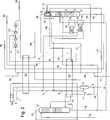
Im Folgenden soll die Erfindung anhand zweier in den
Die
Die
In den beiden Figuren sind gleiche Anlagenteile und Verfahrensströme mit den gleichen Bezugszeichen gekennzeichnet.In the two figures, the same system parts and process streams are identified by the same reference numerals.
In
Im zweiten Wärmetauscher E2 wird der Einsatzstrom
Die H2-Trennkolonne T1, die bei einem Druck betrieben wird, der zwischen einem Fünftel und einem Drittel des Drucks des Einsatzgases
Die wasserstoffreiche Kopffraktion
Die für den Prozess benötigte Spitzenkälte wird über einen durch den mit drei Stufen C1, C2 und C3 ausgeführten Kreislaufverdichter V angetriebenen Kältekreislauf erhalten, in dem Kohlenmonoxid als Kältemittel zirkuliert. Kohlenmonoxid
Das im Kondensator E3 kondensierte Kohlenmonoxid
Im Sumpfraum S der CO/CH4-Trennkolonne T2 sammelt sich eine methanreiche, Kohlenmonoxid enthaltende Flüssigphase
Im Ausführungsbeispiel der
Der Kaminboden K ist mit einem Überlauf U ausgeführt, über den Flüssigkeit in den unterhalb gelegenen Kolonnenabschnitt und den Sumpfraum S' der CO/CH4-Trennkolonne T2' gelangt. Der Sumpfraum S' ist mit einem zweiten Reboiler R2 verbunden, über den dem ersten Teilstrom
Die weitgehend wasserstofffreie, aus Kohlenmonoxid und Methan bestehende Sumpffraktion
Claims (14)
Translated fromGermanPriority Applications (3)
| Application Number | Priority Date | Filing Date | Title |
|---|---|---|---|
| DE102016002225.6ADE102016002225A1 (en) | 2016-02-25 | 2016-02-25 | Process and apparatus for cryogenic synthesis gas separation |
| PCT/EP2017/000090WO2017144151A1 (en) | 2016-02-25 | 2017-01-26 | Method and device for cryogenic syngas decomposition |
| TW106106315ATW201800333A (en) | 2016-02-25 | 2017-02-24 | Process and device for cryogenic synthesis gas separation |
Applications Claiming Priority (1)
| Application Number | Priority Date | Filing Date | Title |
|---|---|---|---|
| DE102016002225.6ADE102016002225A1 (en) | 2016-02-25 | 2016-02-25 | Process and apparatus for cryogenic synthesis gas separation |
Publications (1)
| Publication Number | Publication Date |
|---|---|
| DE102016002225A1true DE102016002225A1 (en) | 2017-10-05 |
Family
ID=57984876
Family Applications (1)
| Application Number | Title | Priority Date | Filing Date |
|---|---|---|---|
| DE102016002225.6AWithdrawnDE102016002225A1 (en) | 2016-02-25 | 2016-02-25 | Process and apparatus for cryogenic synthesis gas separation |
Country Status (3)
| Country | Link |
|---|---|
| DE (1) | DE102016002225A1 (en) |
| TW (1) | TW201800333A (en) |
| WO (1) | WO2017144151A1 (en) |
Families Citing this family (4)
| Publication number | Priority date | Publication date | Assignee | Title |
|---|---|---|---|---|
| FR3058996B1 (en)* | 2016-11-18 | 2022-01-07 | Air Liquide | METHOD AND PLANT FOR CRYOGENIC SEPARATION OF A GAS MIXTURE BY METHANE WASHING |
| US10520250B2 (en) | 2017-02-15 | 2019-12-31 | Butts Properties, Ltd. | System and method for separating natural gas liquid and nitrogen from natural gas streams |
| CN108332509A (en)* | 2018-03-22 | 2018-07-27 | 上海华林工业气体有限公司 | The HyCO cold box systems of nitrogen use level are saved when a kind of driving |
| FR3100057A1 (en)* | 2019-08-20 | 2021-02-26 | L'Air Liquide, Société Anonyme pour l'Etude et l'Exploitation des Procédés Georges Claude | PROCESS AND APPARATUS FOR THE PRODUCTION OF CARBON MONOXIDE BY PARTIAL CONDENSATION |
Family Cites Families (5)
| Publication number | Priority date | Publication date | Assignee | Title |
|---|---|---|---|---|
| US6161397A (en)* | 1998-08-12 | 2000-12-19 | Air Products And Chemicals, Inc. | Integrated cryogenic and non-cryogenic gas mixture separation |
| US6266976B1 (en)* | 2000-06-26 | 2001-07-31 | Air Products And Chemicals, Inc. | Cryogenic H2 and carbon monoxide production with an impure carbon monoxide expander |
| DE102006051759A1 (en)* | 2006-11-02 | 2008-05-08 | Linde Ag | Process and apparatus for decomposing synthesis gas by means of methane scrubbing |
| DE102007013325A1 (en)* | 2007-03-20 | 2008-09-25 | Linde Ag | Process and apparatus for recovering gas products and liquid methane from synthesis gas |
| DE102008059716A1 (en)* | 2008-11-29 | 2010-06-02 | Linde Ag | Process for minimizing recycle gas in a condensation process |
- 2016
- 2016-02-25DEDE102016002225.6Apatent/DE102016002225A1/ennot_activeWithdrawn
- 2017
- 2017-01-26WOPCT/EP2017/000090patent/WO2017144151A1/ennot_activeCeased
- 2017-02-24TWTW106106315Apatent/TW201800333A/enunknown
Also Published As
| Publication number | Publication date |
|---|---|
| TW201800333A (en) | 2018-01-01 |
| WO2017144151A1 (en) | 2017-08-31 |
Similar Documents
| Publication | Publication Date | Title |
|---|---|---|
| DE2920270C2 (en) | Process for generating oxygen | |
| DE69210009T2 (en) | High pressure air separation cycles with multiple reboiler and double column and their integration in gas turbines | |
| EP0092770B1 (en) | Process for obtaining carbon monoxide | |
| DE69504398T2 (en) | Method and device for separating a gas mixture | |
| DE69915722T2 (en) | Process and apparatus for the production of carbon monoxide and hydrogen | |
| EP0100923B1 (en) | Process and apparatus for separating a gas mixture | |
| DE2524179A1 (en) | PROCESS AND SYSTEM FOR COOLING A GAS MIXTURE | |
| DE60031256T2 (en) | VARIABLE LOAD DEVICE AND CORRESPONDING METHOD FOR SEPARATING A USE MIXTURE | |
| DE69905426T2 (en) | Process for the preparation of carbon monoxide | |
| DE69503095T2 (en) | Air separation | |
| DE69209572T2 (en) | Process for the production of the purest nitrogen | |
| DE69320116T2 (en) | Air separation | |
| DE69305317T2 (en) | Air separation process and plant for producing at least one compressed gas product and at least one liquid | |
| DE19803437A1 (en) | Oxygen and nitrogen extracted by low-temperature fractional distillation | |
| DE69004994T3 (en) | Air separation. | |
| EP0669509A1 (en) | Process and apparatus for obtaining pure argon | |
| DE2116326A1 (en) | Method and device for separating gas mixtures | |
| DE69814519T2 (en) | Cryogenic process with double acid and external evaporator condenser for an oxygen and nitrogen mixture | |
| WO2016128110A1 (en) | Combined removal of heavies and lights from natural gas | |
| DE102016002225A1 (en) | Process and apparatus for cryogenic synthesis gas separation | |
| DE69613066T2 (en) | Cryogenic air separation plant for the production of ultra high purity oxygen | |
| DE69709234T2 (en) | Air separation method and apparatus | |
| DE69004647T2 (en) | Method and device for the low-temperature separation of air. | |
| DE3107151A1 (en) | Process and apparatus for liquifying and fractionating air | |
| DE102017006552A1 (en) | Process for the recovery of gas products |
Legal Events
| Date | Code | Title | Description |
|---|---|---|---|
| R081 | Change of applicant/patentee | Owner name:LINDE GMBH, DE Free format text:FORMER OWNER: LINDE AKTIENGESELLSCHAFT, 80331 MUENCHEN, DE | |
| R119 | Application deemed withdrawn, or ip right lapsed, due to non-payment of renewal fee |