DE102015218094A1 - Drive unit for a massage system and massage system with such a drive unit - Google Patents
Drive unit for a massage system and massage system with such a drive unitDownload PDFInfo
- Publication number
- DE102015218094A1 DE102015218094A1DE102015218094.8ADE102015218094ADE102015218094A1DE 102015218094 A1DE102015218094 A1DE 102015218094A1DE 102015218094 ADE102015218094 ADE 102015218094ADE 102015218094 A1DE102015218094 A1DE 102015218094A1
- Authority
- DE
- Germany
- Prior art keywords
- housing
- drive unit
- thread
- unit according
- engine
- Prior art date
- Legal status (The legal status is an assumption and is not a legal conclusion. Google has not performed a legal analysis and makes no representation as to the accuracy of the status listed.)
- Ceased
Links
Images


Classifications
- A—HUMAN NECESSITIES
- A61—MEDICAL OR VETERINARY SCIENCE; HYGIENE
- A61H—PHYSICAL THERAPY APPARATUS, e.g. DEVICES FOR LOCATING OR STIMULATING REFLEX POINTS IN THE BODY; ARTIFICIAL RESPIRATION; MASSAGE; BATHING DEVICES FOR SPECIAL THERAPEUTIC OR HYGIENIC PURPOSES OR SPECIFIC PARTS OF THE BODY
- A61H23/00—Percussion or vibration massage, e.g. using supersonic vibration; Suction-vibration massage; Massage with moving diaphragms
- A61H23/02—Percussion or vibration massage, e.g. using supersonic vibration; Suction-vibration massage; Massage with moving diaphragms with electric or magnetic drive
- A61H23/0254—Percussion or vibration massage, e.g. using supersonic vibration; Suction-vibration massage; Massage with moving diaphragms with electric or magnetic drive with rotary motor
- A61H23/0263—Percussion or vibration massage, e.g. using supersonic vibration; Suction-vibration massage; Massage with moving diaphragms with electric or magnetic drive with rotary motor using rotating unbalanced masses
- A—HUMAN NECESSITIES
- A61—MEDICAL OR VETERINARY SCIENCE; HYGIENE
- A61H—PHYSICAL THERAPY APPARATUS, e.g. DEVICES FOR LOCATING OR STIMULATING REFLEX POINTS IN THE BODY; ARTIFICIAL RESPIRATION; MASSAGE; BATHING DEVICES FOR SPECIAL THERAPEUTIC OR HYGIENIC PURPOSES OR SPECIFIC PARTS OF THE BODY
- A61H15/00—Massage by means of rollers, balls, e.g. inflatable, chains, or roller chains
- A61H2015/0007—Massage by means of rollers, balls, e.g. inflatable, chains, or roller chains with balls or rollers rotating about their own axis
- A61H2015/0014—Massage by means of rollers, balls, e.g. inflatable, chains, or roller chains with balls or rollers rotating about their own axis cylinder-like, i.e. rollers
- A—HUMAN NECESSITIES
- A61—MEDICAL OR VETERINARY SCIENCE; HYGIENE
- A61H—PHYSICAL THERAPY APPARATUS, e.g. DEVICES FOR LOCATING OR STIMULATING REFLEX POINTS IN THE BODY; ARTIFICIAL RESPIRATION; MASSAGE; BATHING DEVICES FOR SPECIAL THERAPEUTIC OR HYGIENIC PURPOSES OR SPECIFIC PARTS OF THE BODY
- A61H15/00—Massage by means of rollers, balls, e.g. inflatable, chains, or roller chains
- A61H2015/0071—Massage by means of rollers, balls, e.g. inflatable, chains, or roller chains with balls or rollers having built-in vibrating means
- A—HUMAN NECESSITIES
- A61—MEDICAL OR VETERINARY SCIENCE; HYGIENE
- A61H—PHYSICAL THERAPY APPARATUS, e.g. DEVICES FOR LOCATING OR STIMULATING REFLEX POINTS IN THE BODY; ARTIFICIAL RESPIRATION; MASSAGE; BATHING DEVICES FOR SPECIAL THERAPEUTIC OR HYGIENIC PURPOSES OR SPECIFIC PARTS OF THE BODY
- A61H2201/00—Characteristics of apparatus not provided for in the preceding codes
- A61H2201/01—Constructive details
- A61H2201/0119—Support for the device
- A61H2201/0153—Support for the device hand-held
- A—HUMAN NECESSITIES
- A61—MEDICAL OR VETERINARY SCIENCE; HYGIENE
- A61H—PHYSICAL THERAPY APPARATUS, e.g. DEVICES FOR LOCATING OR STIMULATING REFLEX POINTS IN THE BODY; ARTIFICIAL RESPIRATION; MASSAGE; BATHING DEVICES FOR SPECIAL THERAPEUTIC OR HYGIENIC PURPOSES OR SPECIFIC PARTS OF THE BODY
- A61H2201/00—Characteristics of apparatus not provided for in the preceding codes
- A61H2201/02—Characteristics of apparatus not provided for in the preceding codes heated or cooled
- A61H2201/0214—Characteristics of apparatus not provided for in the preceding codes heated or cooled cooled
- A—HUMAN NECESSITIES
- A61—MEDICAL OR VETERINARY SCIENCE; HYGIENE
- A61H—PHYSICAL THERAPY APPARATUS, e.g. DEVICES FOR LOCATING OR STIMULATING REFLEX POINTS IN THE BODY; ARTIFICIAL RESPIRATION; MASSAGE; BATHING DEVICES FOR SPECIAL THERAPEUTIC OR HYGIENIC PURPOSES OR SPECIFIC PARTS OF THE BODY
- A61H2201/00—Characteristics of apparatus not provided for in the preceding codes
- A61H2201/02—Characteristics of apparatus not provided for in the preceding codes heated or cooled
- A61H2201/0221—Mechanism for heating or cooling
- A61H2201/0242—Mechanism for heating or cooling by a fluid circulating in the apparatus
- A—HUMAN NECESSITIES
- A61—MEDICAL OR VETERINARY SCIENCE; HYGIENE
- A61H—PHYSICAL THERAPY APPARATUS, e.g. DEVICES FOR LOCATING OR STIMULATING REFLEX POINTS IN THE BODY; ARTIFICIAL RESPIRATION; MASSAGE; BATHING DEVICES FOR SPECIAL THERAPEUTIC OR HYGIENIC PURPOSES OR SPECIFIC PARTS OF THE BODY
- A61H2201/00—Characteristics of apparatus not provided for in the preceding codes
- A61H2201/50—Control means thereof
- A61H2201/5005—Control means thereof for controlling frequency distribution, modulation or interference of a driving signal
- A—HUMAN NECESSITIES
- A61—MEDICAL OR VETERINARY SCIENCE; HYGIENE
- A61H—PHYSICAL THERAPY APPARATUS, e.g. DEVICES FOR LOCATING OR STIMULATING REFLEX POINTS IN THE BODY; ARTIFICIAL RESPIRATION; MASSAGE; BATHING DEVICES FOR SPECIAL THERAPEUTIC OR HYGIENIC PURPOSES OR SPECIFIC PARTS OF THE BODY
- A61H2201/00—Characteristics of apparatus not provided for in the preceding codes
- A61H2201/50—Control means thereof
- A61H2201/5023—Interfaces to the user
- A61H2201/5025—Activation means
Landscapes
- Health & Medical Sciences (AREA)
- Epidemiology (AREA)
- Pain & Pain Management (AREA)
- Physical Education & Sports Medicine (AREA)
- Rehabilitation Therapy (AREA)
- Life Sciences & Earth Sciences (AREA)
- Animal Behavior & Ethology (AREA)
- General Health & Medical Sciences (AREA)
- Public Health (AREA)
- Veterinary Medicine (AREA)
- Percussion Or Vibration Massage (AREA)
Abstract
Translated fromGermanDescription
Translated fromGermanDie Erfindung betrifft eine Antriebseinheit für ein Massagesystem, wobei die Antriebseinheit zumindest teilweise in einen Massagekörper des Massagesystems einführbar ist und wobei die Antriebseinheit Folgendes aufweist:
- a) Einen elektrischen Motor;
- b) Eine mittelbar oder unmittelbar von dem Motor angetriebene Unwucht, um die Antriebseinheit zu Vibrationen anzuregen;
- c) Ein Gehäuse, in dem der Motor und die Unwucht angeordnet sind;
- d) Eine erste Endscheibe am in Längsrichtung des Gehäuses betrachteten ersten Ende des Gehäuses;
- e) Einen Deckel im Bereich des in Längsrichtung des Gehäuses betrachteten zweiten Ende des Gehäuses, wobei der Deckel eine zweite Endscheibe aufweist, die der ersten Endscheibe gegenüberliegt.
- a) an electric motor;
- b) an imbalance driven directly or indirectly by the motor to cause the drive unit to vibrate;
- c) A housing in which the motor and the imbalance are arranged;
- d) a first end plate on the viewed in the longitudinal direction of the housing first end of the housing;
- e) A lid in the region of the viewed in the longitudinal direction of the housing second end of the housing, wherein the lid has a second end plate, which is opposite to the first end plate.
Eine solche Antriebseinheit ist unter der Bezeichnung „Blackroll-Set-Vyper” auf dem Markt erhältlich. Die bekannte Antriebseinheit weist an beiden Endscheiben Bedienelemente zur Steuerung der Antriebseinheit auf. Zur Demontage und Montage der bekannten Antriebseinheit von dem bzw. an den Massagekörper muss zumindest eine Endscheibe entfernt werden. Beim Entfernen bzw. Montieren dieser Endscheibe müssen elektrische Leitungen getrennt bzw. verbunden werden. Hierdurch ist das Nachrüsten oder Austauschen einer Antriebseinheit für einen Endkunden bzw. für einen Endnutzer nur schwer zu bewältigen.Such a drive unit is available on the market under the name "Blackroll Set Vyper". The known drive unit has operating elements for controlling the drive unit on both end disks. For disassembly and assembly of the known drive unit from or to the massage body, at least one end plate must be removed. When removing or mounting this end plate electrical lines must be disconnected or connected. As a result, the retrofitting or replacement of a drive unit for an end user or for an end user is difficult to handle.
Eine weitere gattungsgemäße Antriebseinheit ist unter der Bezeichnung „Power-Roll” auf dem Markt erhältlich. Auch die Power-Roll weist an beiden Endscheiben elektrische Komponenten auf, wodurch die bekannte Antriebseinheit für einen Endkunden bzw. Verbraucher nur aufwändig austauschbar ist.Another generic drive unit is available on the market under the name "Power Roll". The power roll has electrical components on both end plates, as a result of which the known drive unit is only extensively exchangeable for an end customer or consumer.
Beide vorgenannten Antriebseinheiten weisen weiterhin zur Montage und Demontage der Antriebseinheit zumindest eine Endscheibe auf, die mittels einer oder mehreren Schrauben mit dem Gehäuse verbunden sind. Die axiale Länge der Antriebseinheit ist festgelegt. Hierdurch sind die bekannten Antriebseinheiten nicht an unterschiedlich lange Massagekörper adaptierbar.Both aforementioned drive units furthermore have at least one end disk for mounting and dismounting the drive unit, which are connected to the housing by means of one or more screws. The axial length of the drive unit is fixed. As a result, the known drive units are not adaptable to different length massage body.
Aus der
Weiterhin sind in Massagekörpern angeordnete vibrierende Antriebseinheiten aus der
Schließlich offenbart die
Aufgabe der vorliegenden Erfindung ist es demgegenüber, eine Antriebseinheit und ein Massagesystem mit einer solchen Antriebseinheit zu schaffen, wobei die Antriebseinheit trotz einfachster konstruktiver Ausbildung leicht für einen Verbraucher an einen Massagekörper des Massagesystems montierbar und von dem Massagekörper demontierbar ist.Object of the present invention is in contrast to provide a drive unit and a massage system with such a drive unit, wherein the drive unit can be easily assembled for a consumer to a massage body of the massage system and disassembled from the massage body despite the simplest constructive training.
Diese Aufgabe wird durch eine Antriebseinheit mit den Merkmalen des Patentanspruchs 1 sowie durch ein Massagesystem mit den Merkmalen des Patentanspruchs 15 gelöst. Die Unteransprüche geben zweckmäßige Weiterbildungen an.This object is achieved by a drive unit having the features of patent claim 1 and by a massage system having the features of patent claim 15. The dependent claims indicate expedient developments.
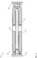
Die erfindungsgemäße Aufgabe wird somit gelöst durch eine Antriebseinheit für ein Massagesystem. Die Antriebseinheit ist zumindest abschnittsweise an einen Massagekörper des Massagesystems anordenbar. Die Antriebseinheit umfasst einen elektrischen Motor. Der Motor ist mittelbar oder unmittelbar mit einer Unwucht verbunden, wobei die Unwucht bei einer Drehung des Motors die Antriebseinheit vibrieren lässt. In dem Gehäuse sind der Motor und die Unwucht angeordnet. Das Gehäuse wird in seiner axialen Längserstreckung durch Endscheiben begrenzt. Eine Endscheibe ist dabei Teil eines Deckels, der mit dem Gehäuse in Verbindung steht. Die Verbindung zwischen Deckel und Gehäuse erfolgt dabei durch ein Deckelgewinde im Deckel, das in ein Gehäusegewinde des Gehäuses eingreift.The object according to the invention is thus achieved by a drive unit for a massage system. The drive unit can be arranged at least in sections on a massage body of the massage system. The drive unit includes an electric motor. The motor is directly or indirectly connected to imbalance, the imbalance causing the drive unit to vibrate as the motor rotates. The motor and the imbalance are arranged in the housing. The housing is limited in its axial longitudinal extent by end plates. An end plate is part of a lid, which is in communication with the housing. The connection between the cover and the housing is effected by a cover thread in the lid, which engages in a housing thread of the housing.
Die Gewindeverbindung zwischen Deckel und Gehäuse ermöglicht eine axiale Längenverstellung des Abstands der beiden Endscheiben. Hierdurch können axial unterschiedlich lange Massagekörper zwischen die beiden Endscheiben gespannt werden. Mit anderen Worten ermöglicht die erfindungsgemäße Antriebseinheit generell einen axialen Längenausgleich und somit eine Adaptierbarkeit an unterschiedlich lange Massagekörper.The threaded connection between the cover and housing allows axial length adjustment of the distance between the two end plates. As a result, axially differently long massage body can be stretched between the two end plates. In other words, the drive unit according to the invention generally allows an axial length compensation and thus an adaptability to differently long massage body.
Bei der Montage der Antriebseinheit muss der Benutzer lediglich das Gehäuse am Massagekörper anordnen und anschließend den Deckel auf das Gehäuse aufschrauben, bis der Massagekörper zumindest teilweise fest von den beiden Endscheiben eingespannt ist. Durch das in das Gehäusegewinde eingreifende Deckelgewinde wird vorzugsweise ein axialer Längenausgleich von ca. 1 cm ermöglicht.When installing the drive unit, the user only has to arrange the housing on the massage body and then screw the cover onto the housing until the massage body is at least partially clamped firmly by the two end disks. By engaging in the housing thread cover thread an axial length compensation of about 1 cm is preferably made possible.
Um die Antriebseinheit weitestgehend formschlüssig in eine kreisquerschnittförmige Durchgangsausnehmung des Massagekörpers einführen zu können, ist das Gehäuse vorzugsweise zylinderförmig ausgebildet. In order to introduce the drive unit largely positively in a circular cross-section through-hole of the massage body, the housing is preferably cylindrical.
Die Antriebseinheit kann über eine externe Spannungsversorgung mit Spannung versorgt werden. Beispielsweise kann die Antriebseinheit von einer Bordspannung eines Lastkraftwagens oder Automobils mit Spannung versorgt werden. Alternativ oder zusätzlich dazu kann die Antriebseinheit eine Batterie und/oder einen Akkumulator aufweisen. Besonders bevorzugt weist die Antriebseinheit einen wiederaufladbaren Akkumulator auf, sodass die Antriebseinheit besonders benutzerfreundlich und autonom in einem Massagesystem einsetzbar ist.The drive unit can be supplied with voltage via an external power supply. For example, the drive unit can be supplied with voltage from an on-board voltage of a truck or automobile. Alternatively or additionally, the drive unit may comprise a battery and / or an accumulator. Particularly preferably, the drive unit has a rechargeable accumulator, so that the drive unit can be used in a particularly user-friendly and autonomous manner in a massage system.
Die konstruktive Ausbildung der erfindungsgemäßen Antriebseinheit wird weiter vereinfacht, wenn das Deckelgewinde in Form eines Innengewindes und das Gehäusegewinde in Form eines Außengewindes ausgebildet ist.The structural design of the drive unit according to the invention is further simplified when the cover thread is formed in the form of an internal thread and the housing thread in the form of an external thread.
Weiter bevorzugt ist das Gehäuse zumindest zweiteilig ausgebildet, wobei das Gehäuse ein Gehäusebasisteil und ein Gehäusedeckelteil aufweist. Das Gehäusebasisteil ist vorzugsweise abschnittsweise formschlüssig mit dem Gehäusedeckelteil verbindbar. Weiter bevorzugt sind Gehäusebasisteil und Gehäusedeckelteil durch ein Spritzgussverfahren hergestellt.More preferably, the housing is formed at least in two parts, wherein the housing has a housing base part and a housing cover part. The housing base part is preferably partially connected form-fitting manner with the housing cover part. Further preferably, the housing base part and the housing cover part are produced by an injection molding process.
Um die Montage der Antriebseinheit zu erleichtern, kann die erste Endscheibe teilweise formschlüssig mit dem Gehäuse verbindbar sein. Die erste Endscheibe ist dabei weiter bevorzugt Teil eines Abschlussteils, das teilweise zwischen das Gehäusebasisteil und das Gehäusedeckelteil einlegbar ist.In order to facilitate the assembly of the drive unit, the first end plate can be partially positively connected to the housing. The first end plate is more preferably part of a closure part, which is partially inserted between the housing base part and the housing cover part.
In weiter bevorzugter Ausgestaltung der Erfindung weist das Gehäusebasisteil im Bereich des Gehäusegewindes zumindest einen Steg auf. Weiterhin weist das Gehäusedeckelteil im Bereich des Gehäusegewindes zumindest einen weiteren Steg auf. Der zumindest eine Steg des Gehäusebasisteils und der zumindest eine Steg des Gehäusdeckelteils überlappen sich im montierten Zustand des Gehäuses in Längsrichtung des Gehäuses gesehen zumindest teilweise. Das Gehäusegewinde ist dadurch besonders massiv und belastbar ausgebildet.In a further preferred embodiment of the invention, the housing base part in the region of the housing thread on at least one web. Furthermore, the housing cover part has at least one further web in the region of the housing thread. The at least one web of the housing base part and the at least one web of the housing cover part overlap at least partially when viewed in the assembled state of the housing in the longitudinal direction of the housing. The housing thread is thus made particularly solid and resilient.
Weiter bevorzugt sind am Gehäusebasisteil im Bereich des Gehäusegewindes mehrere Stege ausgebildet und am Gehäusedeckelteil im Bereich des Gehäusegewindes mehrere weitere Stege ausgebildet. Die Stege des Gehäusebasisteils überlappen sich dabei im montierten Zustand des Gehäuses zumindest teilweise mit den Stegen des Gehäusedeckelteils. Hierdurch wird das Gehäusegewinde weiter stabilisiert In weiter bevorzugter Ausgestaltung der Erfindung ist das Deckelgewinde und/oder das Gehäusegewinde selbsthemmend ausgebildet. Das Deckelgewinde ist dadurch schwer vom Gehäusegewinde abschraubbar. Hierdurch wird vermieden, dass sich das Deckelgewinde durch die vibrierende Antriebseinheit selbstständig vom Gehäusegewinde löst. Weiter bevorzugt weisen Deckelgewinde und/oder Gehäusegewinde jeweils zwei versetzt zueinander verlaufende Gewindegänge auf, um die Selbsthemmung des Deckelgewindes bzw. Gehäusegewindes zu erreichen.More preferably, a plurality of webs are formed on the housing base part in the region of the housing thread and formed on the housing cover part in the region of the housing thread a plurality of further webs. The webs of the housing base part overlap in the mounted state of the housing at least partially with the webs of the housing cover part. As a result, the housing thread is further stabilized in a further preferred embodiment of the invention, the cover thread and / or the housing thread is self-locking. The cover thread is difficult to unscrew from the housing thread. This avoids that the cover thread is released by the vibrating drive unit automatically from the housing thread. Further preferably, cover threads and / or housing threads each have two mutually offset threads to achieve the self-locking of the cover thread or housing thread.
Um die Montage und Demontage der Antriebseinheit für den Endkunden weiter zu vereinfachen, weist die Antriebseinheit vorzugsweise nur an der ersten Endscheibe zumindest ein Bedienelement und an der zweiten Endscheibe kein Bedienelement auf bzw. ist bedienelementefrei ausgebildet. Hierdurch müssen bei der Montage und Demontage der Antriebseinheit an bzw. von dem Massagekörper keine elektrischen Verbindungen vom Endnutzer geschlossen bzw. geöffnet werden. Aus diesem Grund sind weiter bevorzugt keine Lüfter an den Endscheiben angeordnet.In order to further simplify the assembly and disassembly of the drive unit for the end customer, the drive unit preferably has at least one operating element only at the first end disk and no operating element at the second end disk or is designed to be operator-free. As a result, no electrical connections must be closed or opened by the end user during assembly and disassembly of the drive unit to or from the massage body. For this reason, more preferably no fans are arranged on the end disks.
Die Antriebseinheit soll einerseits leicht in den Massagekörper einführbar sein. Andererseits soll die Antriebseinheit rotationsfest um ihre Längsachse in dem Massagekörper angeordnet sein. Erfindungsgemäß ist daher am Gehäuse, insbesondere am Gehäusebasisteil und/oder am Gehäusedeckelteil ein parallel zur zentrischen Längsachse des Gehäuses verlaufender Längssteg ausgebildet, der im axialen Mittelbereich des Gehäuses radial weiter vorsteht, als in den axialen Endbereichen des Gehäuses. Der Längssteg ist dabei vorzugsweise in Form einer sich in Längsrichtung erstreckenden bogenförmigen Erhebung ausgebildet.The drive unit should on the one hand easily be inserted into the massage body. On the other hand, the drive unit should be arranged rotationally fixed about its longitudinal axis in the massage body. According to the invention, therefore, a longitudinal web extending parallel to the central longitudinal axis of the housing is formed on the housing, in particular on the housing base part and / or on the housing cover part, which projects radially further in the axial center region of the housing than in the axial end regions of the housing. The longitudinal web is preferably formed in the form of a longitudinally extending arcuate elevation.
Das Gehäuse weist vorzugsweise einen radialen Außendurchmesser von 45 mm bis 52 mm oder 8 mm bis 12 mm auf. Hierdurch ist die Antriebseinheit besonders effektiv für Massagezwecke am menschlichen Körper ausgebildet. Das Gehäuse mit einem radialen Außendurchmesser von 45 mm bis 52 mm ist dabei in einen für Rückenmassagen einsetzbaren Massagekörper in Form einer Massagerolle einsetzbar. Das Gehäuse mit einem radialen Außendurchmesser von 8 mm bis 12 mm ist in einen für Gliedmaßenmassagen einsetzbaren Massagekörper in Form einer Massagerolle einsetzbar.The housing preferably has a radial outer diameter of 45 mm to 52 mm or 8 mm to 12 mm. As a result, the drive unit is particularly effective for massaging purposes on the human body. The housing with a radial outer diameter of 45 mm to 52 mm can be used in a usable for back massages massage body in the form of a massage roller. The housing with a radial outer diameter of 8 mm to 12 mm can be used in a usable for limb massages massage body in the form of a massage roller.
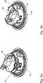
In weiter bevorzugter Ausgestaltung der Antriebseinheit weist die Unwucht eine Lüfterfläche zur axialen Bewegung von Luft in der Antriebseinheit auf. Die Lüfterfläche ist dabei zumindest abschnittsweise schräg zur Längsrichtung des Gehäuses ausgebildet. Die Lüfterfläche weist größtenteils einen Winkel zwischen 1° und 89°, insbesondere zwischen 5° und 85°, vorzugsweise zwischen 10° und 80° zur axialen Längsrichtung des Gehäuses auf. Die Unwucht erfüllt dadurch eine Doppelfunktion indem sie einerseits die Antriebseinheit bei einer Drehung des Motors zum Vibrieren bringt und andererseits eine axiale Luftbewegung zur Kühlung des Motors erzeugt.In a further preferred embodiment of the drive unit, the imbalance on a fan surface for the axial movement of air in the drive unit. The fan surface is at least partially formed obliquely to the longitudinal direction of the housing. The fan surface mostly has an angle between 1 ° and 89 °, in particular between 5 ° and 85 °, preferably between 10 ° and 80 ° to the axial longitudinal direction of the housing. The imbalance thereby fulfills a dual function by on the one hand causes the drive unit to vibrate during rotation of the motor and on the other hand generates an axial air movement for cooling the motor.
In einer Antriebseinheit mit einem Gehäuse, einem Motor und einer Unwucht, wobei die Unwucht eine zuvor beschriebene Lüfterfläche zur axialen Bewegung von Luft aufweist, wird dabei eine eigenständige Erfindung gesehen. Diese eigenständige Erfindung ist mit allen weiteren Merkmalen der Beschreibung beliebig kombinierbar.In a drive unit with a housing, a motor and an imbalance, wherein the imbalance has a previously described fan surface for the axial movement of air, while an independent invention is seen. This independent invention can be combined as desired with all other features of the description.
Weiter bevorzugt weist die Antriebseinheit eine Motorsteuerung auf. Die Motorsteuerung kann zur Steuerung einer periodischen Drehzahlerhöhung und/oder periodischen Drehzahlverminderung des Motors ausgebildet sein. Die Antriebseinheit ist dadurch zur Lockerung unterschiedlicher Muskelgruppen, die bei hochfrequenten bzw. niederfrequenten Vibrationen entsteht, ausgebildet. Die Vibrationen werden dabei vorzugsweise über einen Massagekörper an die Muskelgruppen übertragen. Die Vibrationen können wellenförmig stärker und schwächer werden.More preferably, the drive unit has a motor control. The engine controller may be configured to control a periodic speed increase and / or periodic speed reduction of the engine. The drive unit is thereby designed to relax different muscle groups, which arises in high-frequency or low-frequency vibrations. The vibrations are preferably transmitted via a massage body to the muscle groups. The vibrations can become stronger and weaker undulating.
Weiter bevorzugt ist die Motorsteuerung fernsteuerbar. Hierzu kann die Motorsteuerung eine WLAN-Schnittstelle, eine Bluetooth-Schnittstelle oder eine andere Funkschnittstelle aufweisen.More preferably, the engine control is remotely controllable. For this purpose, the motor control can have a WLAN interface, a Bluetooth interface or another radio interface.
Um die Motordrehzahl an die individuellen Bedürfnisse der Endkunden anpassen zu können, ist die Motorsteuerung vorzugsweise zur stufenlosen Drehzahlsteuerung ausgebildet.In order to adapt the engine speed to the individual needs of the end customer, the motor control is preferably designed for continuously variable speed control.
Weiter bevorzugt kann die Motorsteuerung eine Zeitverzögerung aufweisen, um den Motor im Anschluss an die Betätigung der Motorsteuerung durch einen Benutzer erst nach einer durch die Motorsteuerung bestimmbaren Zeitspanne mit Spannung zu versorgen. Die Zeitverzögerung ermöglicht eine entspannte und bequeme Positionierung der Antriebseinheit, bevor die Vibrationen eine Positionierung erschweren.More preferably, the engine controller may have a time delay to power the engine following actuation of the engine control by a user only after a period of time determinable by the engine control. The time delay allows a relaxed and convenient positioning of the drive unit before the vibrations make positioning difficult.
Besonders bevorzugt weist die Motorsteuerung eine automatische Abschaltfunktion auf, die den Motor nach einer durch die Motorsteuerung bestimmbaren Zeitspanne abschaltet. Dies verhindert Verletzungen aufgrund von zu langen Anwendungen.Particularly preferably, the engine control system has an automatic shut-off function which switches off the engine after a time period which can be determined by the engine control. This prevents injuries due to too long applications.
Die Motorsteuerung kann eine erste Platine und eine zweite Platine aufweisen, wobei die zweite Platine – um Bauraum einzusparen – quer zur ersten Platine angeordnet sein kann. Besonders bevorzugt ist die zweite Platine senkrecht zur ersten Platine angeordnet.The motor controller may include a first board and a second board, wherein the second board - to save space - can be arranged transversely to the first board. Particularly preferably, the second circuit board is arranged perpendicular to the first circuit board.
Die Antriebseinheit kann einen USB-Anschluss aufweisen. Der USB-Anschluss ist besonders bevorzugt in Form eines Mikro-USB-Anschlusses ausgebildet. Durch den USB-Anschluss kann die Motorsteuerung mit Spannung versorgt werden. Weiter bevorzugt ist ein Akkumulator der Antriebseinheit durch über den USB-Anschluss empfangene Spannung aufladbar. Schließlich kann die Motorsteuerung über den USB-Anschluss programmierbar ausgebildet sein. Der USB-Anschluss befindet sich dabei besonders bevorzugt an der Schnittstelle der zweiten Platine, die quer, insbesondere senkrecht, zur ersten Platine angeordnet ist.The drive unit can have a USB connection. The USB port is particularly preferably designed in the form of a micro USB port. Through the USB port, the motor control can be powered. More preferably, an accumulator of the drive unit can be charged by voltage received via the USB connection. Finally, the motor control can be programmable via the USB port. The USB connection is particularly preferably located at the interface of the second circuit board, which is arranged transversely, in particular perpendicular, to the first circuit board.
Die erfindungsgemäße Aufgabe wird weiterhin gelöst durch ein Massagesystem mit einer zuvor beschriebenen Antriebseinheit und einem Massagekörper.The object according to the invention is furthermore achieved by a massage system having a drive unit described above and a massage body.
Der Massagekörper ist insbesondere in Form eines Schaumstoffkörpers ausgebildet. Der Schaumstoffkörper weist vorzugsweise eine Rollenform bzw. Röhrenform auf. Der Röhreninnendurchmesser beträgt dabei vorzugsweise 45 mm bis 52 mm oder 8 mm bis 12 mm. Der Massagekörper kann weiterhin in Form eines Röhrenteils bzw. Rollenteils ausgebildet sein. Beispielsweise kann der Massagekörper in Form einer Lordosenstütze ausgebildet sein. Der Massagekörper ist vorzugsweise axialsymmetrisch zu seiner Längsachse ausgebildet. Er weist insbesondere keine Längsnut in seiner Innendurchgangsausnehmung auf. Der Massagekörper kann an seiner Außenseite Längsrillen aufweisen, um die Massagewirkung zu verbessern.The massage body is designed in particular in the form of a foam body. The foam body preferably has a roll shape or tubular shape. The inner tube diameter is preferably 45 mm to 52 mm or 8 mm to 12 mm. The massage body can furthermore be designed in the form of a tubular part or roller part. For example, the massage body may be in the form of a lumbar support. The massage body is preferably formed axially symmetrical to its longitudinal axis. He has in particular no longitudinal groove in its Innendurchgangsausnehmung. The massage body may have on its outside longitudinal grooves to improve the massage effect.
Der Massagekörper ist besonders bevorzugt aus expandiertem Polypropylen (EPP) ausgebildet. Hierdurch ist der Massagekörper besonders wärmedämmend und stabil ausgebildet.The massage body is particularly preferably formed from expanded polypropylene (EPP). As a result, the massage body is particularly thermally insulating and stable.
Weitere Merkmale und Vorteile der Erfindung ergeben sich aus der nachfolgenden detaillierten Beschreibung eines Ausführungsbeispiels der Erfindung aus den Patentansprüchen sowie anhand der Figuren der Zeichnung, die erfindungswesentliche Einzelheiten zeigt.Further features and advantages of the invention will become apparent from the following detailed description of an embodiment of the invention from the claims and with reference to the figures of the drawing showing essential to the invention details.
Die in der Zeichnung gezeigten Merkmale sind derart dargestellt, dass die erfindungsgemäßen Besonderheiten deutlich sichtbar gemacht werden können. Die verschiedenen Merkmale können je einzeln für sich oder zu mehreren in beliebigen Kombinationen bei Varianten der Erfindung verwirklicht sein.The features shown in the drawing are shown such that the features of the invention can be made clearly visible. The various features may be implemented individually for themselves or for a plurality of combinations in variants of the invention.
Es zeigen:Show it:
Der Massagekörper
Die Antriebseinheit
Die Spannungsversorgung des Motors
Unter Vornahme einer Zusammenschau aller Figuren der Zeichnung betrifft die Erfindung zusammenfassend eine Antriebseinheit
ZITATE ENTHALTEN IN DER BESCHREIBUNG QUOTES INCLUDE IN THE DESCRIPTION
Diese Liste der vom Anmelder aufgeführten Dokumente wurde automatisiert erzeugt und ist ausschließlich zur besseren Information des Lesers aufgenommen. Die Liste ist nicht Bestandteil der deutschen Patent- bzw. Gebrauchsmusteranmeldung. Das DPMA übernimmt keinerlei Haftung für etwaige Fehler oder Auslassungen.This list of the documents listed by the applicant has been generated automatically and is included solely for the better information of the reader. The list is not part of the German patent or utility model application. The DPMA assumes no liability for any errors or omissions.
Zitierte PatentliteraturCited patent literature
- DE 202014004900 U1[0005]DE 202014004900 U1[0005]
- DE 202014004901 U1[0005]DE 202014004901 U1[0005]
- US 2013/0281892 A1[0006]US 2013/0281892 A1[0006]
- US 2005/0070827 A1[0006]US 2005/0070827 A1[0006]
- US 2009/0176635 A1[0006]US 2009/0176635 A1[0006]
- US 8337437 B2[0006]US 8337437 B2[0006]
- US 8500663 B2[0006]US 8500663 B2[0006]
- US 8556837 B1[0006]US 8556837 B1[0006]
- US 2013/0267396 A1[0007]US 2013/0267396 A1[0007]
Claims (15)
Translated fromGermanPriority Applications (3)
| Application Number | Priority Date | Filing Date | Title |
|---|---|---|---|
| DE102015218094.8ADE102015218094A1 (en) | 2015-09-21 | 2015-09-21 | Drive unit for a massage system and massage system with such a drive unit |
| EP16765935.8AEP3313351B1 (en) | 2015-09-21 | 2016-08-26 | Drive unit for a massage system, and massage system comprising a drive unit of said type |
| PCT/EP2016/070243WO2017050525A1 (en) | 2015-09-21 | 2016-08-26 | Drive unit for a massage system, and massage system comprising a drive unit of said type |
Applications Claiming Priority (1)
| Application Number | Priority Date | Filing Date | Title |
|---|---|---|---|
| DE102015218094.8ADE102015218094A1 (en) | 2015-09-21 | 2015-09-21 | Drive unit for a massage system and massage system with such a drive unit |
Publications (1)
| Publication Number | Publication Date |
|---|---|
| DE102015218094A1true DE102015218094A1 (en) | 2017-03-23 |
Family
ID=56926155
Family Applications (1)
| Application Number | Title | Priority Date | Filing Date |
|---|---|---|---|
| DE102015218094.8ACeasedDE102015218094A1 (en) | 2015-09-21 | 2015-09-21 | Drive unit for a massage system and massage system with such a drive unit |
Country Status (3)
| Country | Link |
|---|---|
| EP (1) | EP3313351B1 (en) |
| DE (1) | DE102015218094A1 (en) |
| WO (1) | WO2017050525A1 (en) |
Cited By (1)
| Publication number | Priority date | Publication date | Assignee | Title |
|---|---|---|---|---|
| DE202018102706U1 (en) | 2018-05-15 | 2019-08-19 | Blackroll Ag | Receiving device for a vibration module and training system |
Families Citing this family (2)
| Publication number | Priority date | Publication date | Assignee | Title |
|---|---|---|---|---|
| US11622909B2 (en) | 2019-11-04 | 2023-04-11 | Therabody, Inc. | Massage roller assembly |
| US11690780B2 (en) | 2019-11-04 | 2023-07-04 | Therabody, Inc. | Vibrating massage roller with multiple motors |
Citations (11)
| Publication number | Priority date | Publication date | Assignee | Title |
|---|---|---|---|---|
| DE2033766A1 (en)* | 1970-07-08 | 1972-01-20 | Buchmann, Rudolf C , 6800 Mannheim Feudenheim | Massage and gym equipment |
| US5637065A (en)* | 1996-07-25 | 1997-06-10 | Chang; Sreter | Massage exercise bar device |
| US20050070827A1 (en) | 2003-09-29 | 2005-03-31 | Kwang-Ho Lee | Cushion apparatus for recovery from fatigue |
| US20090176635A1 (en) | 2008-01-09 | 2009-07-09 | Todd Brinson | Exercise Device |
| US8337437B2 (en) | 2006-03-24 | 2012-12-25 | Sue Hitzmann | System and methods for promoting health |
| US8500663B2 (en) | 2008-11-06 | 2013-08-06 | Health E Company | Vibrating massage roller utilizing a plurality of supports and eccentric weights |
| US20130267396A1 (en) | 2007-07-11 | 2013-10-10 | Kipp K. Dye | Therapeutic, fitness, and sports enhancement device |
| US8556837B1 (en) | 2009-08-26 | 2013-10-15 | M-F Athletic Company, Inc. | Therapeutic roller apparatus |
| US20130281892A1 (en) | 2008-11-06 | 2013-10-24 | Health E Company | Vibrating massage roller |
| DE202014004901U1 (en) | 2014-06-18 | 2014-09-04 | Medisana Ag | Device for promoting blood circulation and for stimulating skin and muscle areas of the human body |
| DE202014004900U1 (en) | 2014-06-18 | 2014-09-04 | Medisana Ag | Device for promoting blood circulation and for stimulating skin and muscle areas of the human body |
Family Cites Families (4)
| Publication number | Priority date | Publication date | Assignee | Title |
|---|---|---|---|---|
| US5209227A (en)* | 1990-09-25 | 1993-05-11 | Richard Deutsch | Thermoelectric therapy device and moisturizing device therefor |
| SG150406A1 (en)* | 2007-08-29 | 2009-03-30 | Vibrasys Pte Ltd | Portable massage device |
| CN201182301Y (en)* | 2008-04-09 | 2009-01-21 | 刘胜 | Electric hair drying blower cover with massage function |
| CH703479A2 (en)* | 2010-07-21 | 2012-02-15 | Arne Koss | Health couch i.e. wellness- and massage couch, for therapeutic applications for elder person in clinic, has line guide that accommodates storage and function cushions, and arm support surfaces that exhibit surface property |
- 2015
- 2015-09-21DEDE102015218094.8Apatent/DE102015218094A1/ennot_activeCeased
- 2016
- 2016-08-26WOPCT/EP2016/070243patent/WO2017050525A1/ennot_activeCeased
- 2016-08-26EPEP16765935.8Apatent/EP3313351B1/enactiveActive
Patent Citations (11)
| Publication number | Priority date | Publication date | Assignee | Title |
|---|---|---|---|---|
| DE2033766A1 (en)* | 1970-07-08 | 1972-01-20 | Buchmann, Rudolf C , 6800 Mannheim Feudenheim | Massage and gym equipment |
| US5637065A (en)* | 1996-07-25 | 1997-06-10 | Chang; Sreter | Massage exercise bar device |
| US20050070827A1 (en) | 2003-09-29 | 2005-03-31 | Kwang-Ho Lee | Cushion apparatus for recovery from fatigue |
| US8337437B2 (en) | 2006-03-24 | 2012-12-25 | Sue Hitzmann | System and methods for promoting health |
| US20130267396A1 (en) | 2007-07-11 | 2013-10-10 | Kipp K. Dye | Therapeutic, fitness, and sports enhancement device |
| US20090176635A1 (en) | 2008-01-09 | 2009-07-09 | Todd Brinson | Exercise Device |
| US8500663B2 (en) | 2008-11-06 | 2013-08-06 | Health E Company | Vibrating massage roller utilizing a plurality of supports and eccentric weights |
| US20130281892A1 (en) | 2008-11-06 | 2013-10-24 | Health E Company | Vibrating massage roller |
| US8556837B1 (en) | 2009-08-26 | 2013-10-15 | M-F Athletic Company, Inc. | Therapeutic roller apparatus |
| DE202014004901U1 (en) | 2014-06-18 | 2014-09-04 | Medisana Ag | Device for promoting blood circulation and for stimulating skin and muscle areas of the human body |
| DE202014004900U1 (en) | 2014-06-18 | 2014-09-04 | Medisana Ag | Device for promoting blood circulation and for stimulating skin and muscle areas of the human body |
Cited By (1)
| Publication number | Priority date | Publication date | Assignee | Title |
|---|---|---|---|---|
| DE202018102706U1 (en) | 2018-05-15 | 2019-08-19 | Blackroll Ag | Receiving device for a vibration module and training system |
Also Published As
| Publication number | Publication date |
|---|---|
| EP3313351A1 (en) | 2018-05-02 |
| WO2017050525A1 (en) | 2017-03-30 |
| EP3313351B1 (en) | 2020-02-26 |
Similar Documents
| Publication | Publication Date | Title |
|---|---|---|
| DE202016104211U1 (en) | Drive unit for a massage system and massage system with such a drive unit | |
| DE102010045899B3 (en) | Fan unit with an electric axial fan | |
| EP3313351B1 (en) | Drive unit for a massage system, and massage system comprising a drive unit of said type | |
| EP3126705B1 (en) | Tuned mass damper for a vehicle seat, vehicle seat, and motor vehicle | |
| DE102010045833A1 (en) | Fastening unit for use in mounting unit, has projecting retaining flange arranged at end of spacer, and retaining element whose end includes constriction that positively engages flange for securing retaining element at spacer | |
| EP1015782A1 (en) | Elastic articulated body | |
| EP1940594A1 (en) | Portable power tool | |
| DE102011104386A1 (en) | Fastening device for fastening component e.g. tail lamp at chassis of vehicle, has cap which is moved for tensioning spring element such that threads and spring element are moved so as to fix the component to vehicle chassis | |
| DE102013000111A1 (en) | Filtering apparatus for intake air of internal combustion engine, has filter insert comprising connecting element for arrangement of inlet portion and outlet portion, and strut supported in axially non-displaceable manner in filter insert | |
| DE102015109726A1 (en) | spice mill | |
| DE102015011801A1 (en) | Filter with barb-shaped bayonet mount and filter element | |
| DE112024000089T5 (en) | Offset pulse generator for car seat massage and massage system | |
| EP1955747B1 (en) | Child's toy, in particular a child's vehicle with a front-end loader | |
| DE102017202014B4 (en) | Damper bearing | |
| DE102014007844A1 (en) | rotary damper | |
| EP2060379B1 (en) | Vibration isolating support | |
| DE102016215571B4 (en) | Seat with a mounting arrangement of an electric motor | |
| DE102008057036A1 (en) | Beduftungsvorrichtung | |
| DE102014116439A1 (en) | Device for actuating assemblies with a cylindrical body | |
| DE102014100781A1 (en) | vibration | |
| EP2600503B1 (en) | Brush support for a brush commuted electric motor and electric motor | |
| DE102015007182A1 (en) | Filter element and filter system | |
| DE102012020211A1 (en) | Modularly constructed toy vehicle i.e. motor car, has module-body module, front light module, rear light module, guidance module, base module, rear wheel module and drive module releasably connected with one another by screws | |
| WO2013060397A1 (en) | Decoupling element and arrangement for fastening a functional module to a vehicle part in a vibration-decoupled manner and method for producing same | |
| WO2019072926A1 (en) | HYBRID RETROFIT KIT FOR RETROFITTING A VEHICLE DRIVEN WITH A COMBUSTION ENGINE |
Legal Events
| Date | Code | Title | Description |
|---|---|---|---|
| R163 | Identified publications notified | ||
| R012 | Request for examination validly filed | ||
| R002 | Refusal decision in examination/registration proceedings | ||
| R003 | Refusal decision now final |