DE102015218019A1 - A magnetostrated cryostat comprising an LTS region and an HTS region - Google Patents
A magnetostrated cryostat comprising an LTS region and an HTS regionDownload PDFInfo
- Publication number
- DE102015218019A1 DE102015218019A1DE102015218019.0ADE102015218019ADE102015218019A1DE 102015218019 A1DE102015218019 A1DE 102015218019A1DE 102015218019 ADE102015218019 ADE 102015218019ADE 102015218019 A1DE102015218019 A1DE 102015218019A1
- Authority
- DE
- Germany
- Prior art keywords
- lts
- hts
- cryostat
- section
- area
- Prior art date
- Legal status (The legal status is an assumption and is not a legal conclusion. Google has not performed a legal analysis and makes no representation as to the accuracy of the status listed.)
- Granted
Links
- 239000002887superconductorSubstances0.000claimsabstractdescription8
- 239000001307heliumSubstances0.000claimsdescription69
- 229910052734heliumInorganic materials0.000claimsdescription69
- SWQJXJOGLNCZEY-UHFFFAOYSA-Nhelium atomChemical compound[He]SWQJXJOGLNCZEY-UHFFFAOYSA-N0.000claimsdescription69
- 238000000034methodMethods0.000claimsdescription30
- 239000004020conductorSubstances0.000claimsdescription27
- 230000005855radiationEffects0.000claimsdescription21
- 230000008859changeEffects0.000claimsdescription4
- 230000002829reductive effectEffects0.000claimsdescription4
- 239000007789gasSubstances0.000claimsdescription3
- 230000002441reversible effectEffects0.000claimsdescription2
- 238000010276constructionMethods0.000abstractdescription5
- 239000010410layerSubstances0.000description24
- 239000000463materialSubstances0.000description16
- 238000005481NMR spectroscopyMethods0.000description12
- 230000008569processEffects0.000description12
- IJGRMHOSHXDMSA-UHFFFAOYSA-NAtomic nitrogenChemical compoundN#NIJGRMHOSHXDMSA-UHFFFAOYSA-N0.000description10
- 239000007788liquidSubstances0.000description10
- 230000007704transitionEffects0.000description10
- 238000005259measurementMethods0.000description8
- 229910000657niobium-tinInorganic materials0.000description8
- 230000002085persistent effectEffects0.000description8
- 229910021521yttrium barium copper oxideInorganic materials0.000description8
- 238000011161developmentMethods0.000description7
- 230000008878couplingEffects0.000description5
- 238000010168coupling processMethods0.000description5
- 238000005859coupling reactionMethods0.000description5
- 230000004907fluxEffects0.000description5
- 238000004519manufacturing processMethods0.000description5
- 229910052757nitrogenInorganic materials0.000description5
- 230000001939inductive effectEffects0.000description4
- 238000005496temperingMethods0.000description4
- 238000001816coolingMethods0.000description3
- 238000013461designMethods0.000description3
- 230000001965increasing effectEffects0.000description3
- 238000009413insulationMethods0.000description3
- 239000000758substrateSubstances0.000description3
- 229910002367SrTiOInorganic materials0.000description2
- 239000010949copperSubstances0.000description2
- 238000000151depositionMethods0.000description2
- 238000010586diagramMethods0.000description2
- 229910000856hastalloyInorganic materials0.000description2
- 239000012774insulation materialSubstances0.000description2
- VEALVRVVWBQVSL-UHFFFAOYSA-Nstrontium titanateChemical compound[Sr+2].[O-][Ti]([O-])=OVEALVRVVWBQVSL-UHFFFAOYSA-N0.000description2
- BUHVIAUBTBOHAG-FOYDDCNASA-N(2r,3r,4s,5r)-2-[6-[[2-(3,5-dimethoxyphenyl)-2-(2-methylphenyl)ethyl]amino]purin-9-yl]-5-(hydroxymethyl)oxolane-3,4-diolChemical compoundCOC1=CC(OC)=CC(C(CNC=2C=3N=CN(C=3N=CN=2)[C@H]2[C@@H]([C@H](O)[C@@H](CO)O2)O)C=2C(=CC=CC=2)C)=C1BUHVIAUBTBOHAG-FOYDDCNASA-N0.000description1
- 241001136792AlleSpecies0.000description1
- RYGMFSIKBFXOCR-UHFFFAOYSA-NCopperChemical compound[Cu]RYGMFSIKBFXOCR-UHFFFAOYSA-N0.000description1
- 229910000831SteelInorganic materials0.000description1
- 238000009825accumulationMethods0.000description1
- 230000002411adverseEffects0.000description1
- 230000002776aggregationEffects0.000description1
- 238000004220aggregationMethods0.000description1
- 238000004458analytical methodMethods0.000description1
- 230000009286beneficial effectEffects0.000description1
- 238000009835boilingMethods0.000description1
- 239000011248coating agentSubstances0.000description1
- 238000000576coating methodMethods0.000description1
- 150000001875compoundsChemical class0.000description1
- 229910052802copperInorganic materials0.000description1
- 230000007423decreaseEffects0.000description1
- 230000008021depositionEffects0.000description1
- 238000005553drillingMethods0.000description1
- 230000000694effectsEffects0.000description1
- 238000010292electrical insulationMethods0.000description1
- 230000005611electricityEffects0.000description1
- 238000005516engineering processMethods0.000description1
- 229910052737goldInorganic materials0.000description1
- 238000000669high-field nuclear magnetic resonance spectroscopyMethods0.000description1
- 239000012212insulatorSubstances0.000description1
- 238000005457optimizationMethods0.000description1
- 235000012771pancakesNutrition0.000description1
- 238000000059patterningMethods0.000description1
- 239000010970precious metalSubstances0.000description1
- 239000011241protective layerSubstances0.000description1
- 238000007493shaping processMethods0.000description1
- 229910052709silverInorganic materials0.000description1
- 239000002356single layerSubstances0.000description1
- 239000011343solid materialSubstances0.000description1
- 230000003595spectral effectEffects0.000description1
- 230000003068static effectEffects0.000description1
- 239000010959steelSubstances0.000description1
- 239000010409thin filmSubstances0.000description1
- 238000000427thin-film depositionMethods0.000description1
- 238000012546transferMethods0.000description1
- 238000004804windingMethods0.000description1
Images


Classifications
- G—PHYSICS
- G01—MEASURING; TESTING
- G01R—MEASURING ELECTRIC VARIABLES; MEASURING MAGNETIC VARIABLES
- G01R33/00—Arrangements or instruments for measuring magnetic variables
- G01R33/20—Arrangements or instruments for measuring magnetic variables involving magnetic resonance
- G01R33/28—Details of apparatus provided for in groups G01R33/44 - G01R33/64
- G01R33/38—Systems for generation, homogenisation or stabilisation of the main or gradient magnetic field
- G01R33/3804—Additional hardware for cooling or heating of the magnet assembly, for housing a cooled or heated part of the magnet assembly or for temperature control of the magnet assembly
- G—PHYSICS
- G01—MEASURING; TESTING
- G01R—MEASURING ELECTRIC VARIABLES; MEASURING MAGNETIC VARIABLES
- G01R33/00—Arrangements or instruments for measuring magnetic variables
- G01R33/20—Arrangements or instruments for measuring magnetic variables involving magnetic resonance
- G01R33/28—Details of apparatus provided for in groups G01R33/44 - G01R33/64
- G01R33/38—Systems for generation, homogenisation or stabilisation of the main or gradient magnetic field
- G01R33/381—Systems for generation, homogenisation or stabilisation of the main or gradient magnetic field using electromagnets
- G01R33/3815—Systems for generation, homogenisation or stabilisation of the main or gradient magnetic field using electromagnets with superconducting coils, e.g. power supply therefor
- H—ELECTRICITY
- H01—ELECTRIC ELEMENTS
- H01F—MAGNETS; INDUCTANCES; TRANSFORMERS; SELECTION OF MATERIALS FOR THEIR MAGNETIC PROPERTIES
- H01F6/00—Superconducting magnets; Superconducting coils
- H—ELECTRICITY
- H01—ELECTRIC ELEMENTS
- H01F—MAGNETS; INDUCTANCES; TRANSFORMERS; SELECTION OF MATERIALS FOR THEIR MAGNETIC PROPERTIES
- H01F6/00—Superconducting magnets; Superconducting coils
- H01F6/04—Cooling
- H—ELECTRICITY
- H01—ELECTRIC ELEMENTS
- H01F—MAGNETS; INDUCTANCES; TRANSFORMERS; SELECTION OF MATERIALS FOR THEIR MAGNETIC PROPERTIES
- H01F6/00—Superconducting magnets; Superconducting coils
- H01F6/06—Coils, e.g. winding, insulating, terminating or casing arrangements therefor
- H—ELECTRICITY
- H03—ELECTRONIC CIRCUITRY
- H03K—PULSE TECHNIQUE
- H03K17/00—Electronic switching or gating, i.e. not by contact-making and –breaking
- H03K17/51—Electronic switching or gating, i.e. not by contact-making and –breaking characterised by the components used
- H03K17/92—Electronic switching or gating, i.e. not by contact-making and –breaking characterised by the components used by the use, as active elements, of superconductive devices
Landscapes
- Physics & Mathematics (AREA)
- Engineering & Computer Science (AREA)
- Power Engineering (AREA)
- Condensed Matter Physics & Semiconductors (AREA)
- General Physics & Mathematics (AREA)
- Electromagnetism (AREA)
- Containers, Films, And Cooling For Superconductive Devices (AREA)
- Magnetic Resonance Imaging Apparatus (AREA)
Abstract
Translated fromGermanDescription
Translated fromGermanDie Erfindung betrifft einen Kryostat mit einer Magnetanordnung zur Erzeugung eines Magnetfelds B0,
wobei die Magnetanordnung einen LTS-Bereich mit mindestens einer LTS-Sektion aus einem konventionellen Tieftemperatursupraleiter und einen HTS-Bereich mit wenigstens einer HTS-Sektion aus einem Hochtemperatursupraleiter umfasst,
wobei der HTS-Bereich radial innerhalb des LTS-Bereichs angeordnet ist, und wobei der Kryostat dazu ausgebildet ist, den LTS-Bereich und den HTS-Bereich unabhängig voneinander zu temperieren.The invention relates to a cryostat having a magnet arrangement for generating a magnetic field B0,
wherein the magnet assembly comprises an LTS region having at least one LTS section from a conventional cryogenic superconductor and an HTS region having at least one HTS section from a high temperature superconductor,
wherein the HTS region is disposed radially within the LTS region, and wherein the cryostat is configured to independently temper the LTS region and the HTS region.
Ein solcher Kryostat ist aus der
Die Kernspinresonanz(=NMR)-Spektroskopie ist ein leistungsfähiges Verfahren der instrumentellen Analytik, das auf der Ausrichtung von Kernspins in einem starken Magnetfeld und deren Verhalten bei Einstrahlung von Hochfrequenzimpulsen basiert. Zur Erzeugung besonders hoher Magnetfeldstärken, die für hohe spektrale Auflösungen benötigt werden, werden üblicherweise NMR-Magnete auf Basis von supraleitenden Spulen eingesetzt.Nuclear magnetic resonance (NMR) spectroscopy is a powerful method of instrumental analysis that is based on the alignment of nuclear spins in a strong magnetic field and their behavior upon irradiation of radio frequency pulses. To generate particularly high magnetic field strengths, which are required for high spectral resolutions, usually NMR magnets based on superconducting coils are used.
Konventionelle NMR-Magnete werden üblicherweise aus Tieftemperatur-Supraleiter(=LTS)-Drähten, insbesondere NbTi- oder Nb3Sn-Drähten, gefertigt. Durch das kritische Feld von Nb3Sn ergibt sich derzeit eine obere Grenze von etwa 23,5 T für die erreichbare Magnetfeldstärke, was in der NMR einer Protonenresonanzfrequenz von 1000 MHz entspricht.Conventional NMR magnets are usually fabricated from low temperature superconductor (= LTS) wires, especially NbTi or Nb3Sn wires. The critical field of Nb3Sn currently results in an upper limit of about 23.5 T for the achievable magnetic field strength, which corresponds to a proton resonance frequency of 1000 MHz in NMR.
Um höhere Feldstärken zu erreichen, oder um einen Magnet gegebener Feldstärke kompakter gestalten zu können, muss auf alternative Leitermaterialien zurückgegriffen werden. Erforscht wird in diesem Zusammenhang hauptsächlich der Einsatz von Hochtemperatursupraleiter(=HTS)-Bandleitern, insbesondere basierend auf YBCO. Mit den HTS-Bandleitern werden üblicherweise solenoidförmige Spulen gewickelt.In order to achieve higher field strengths or to be able to make a magnet of given field strength more compact, alternative conductor materials must be used. In particular, the use of high-temperature superconductor (= HTS) fiber-optic conductors, in particular based on YBCO, is being researched in this context. Solids-shaped coils are usually wound with the HTS strip conductors.
Dabei wird der NMR-Magnet nicht komplett aus HTS-Materialien gefertigt; aus Kostengründen ist es vorteilhaft, nur für die innersten Sektionen HTS heranzuziehen, und den Hintergrundmagneten in konventioneller LTS-Technologie basierend auf NbTi oder Nb3Sn zu fertigen. Üblicherweise wird eine Magnetsektion aus HTS-Bandmaterial gewickelt, und dann mit einem LTS Hintergrundmagnet elektrisch in Serie geschaltet.The NMR magnet is not completely made of HTS materials; For reasons of cost, it is advantageous to use HTS only for the innermost sections and to fabricate the background magnet in conventional LTS technology based on NbTi or Nb3Sn. Usually, a magnetic section of HTS tape is wound, and then electrically connected in series with an LTS background magnet.
Beispielsweise sind in der
HTS-Bandleiter können nur mit begrenzten Längen gefertigt werden, so dass für eine typische NMR-Magnetspule in der Regel supraleitende oder zumindest sehr niederohmige Verbindungsstellen (Joints) von HTS zu HTS nötig sind, was technologisch schwierig ist. Ebenso müssen bei den bekannten Magnetspulensystemen supraleitende oder zumindest sehr niederohmige Verbindungsstellen (Joints) von LTS zu HTS eingerichtet werden, was ebenfalls technologisch schwierig ist. Für die Joints muss im allgemeinen ein Ort mit niedriger Magnetfeldstärke gewählt werden, was oft komplexe Leiterführungen nötig macht. Weiterhin weisen Bandleiter in der Regel über den Querschnitt in gewissem Umfang schwankende Eigenschaften auf, was zu Inhomogenitäten im erzeugten Magnetfeld führt. Ebenso können Abschirmströme in den Bandleitern über die Breite des Bandes zu Inhomogenitäten führen.HTS ribbon conductors can only be manufactured with limited lengths, so that for a typical NMR magnetic coil usually superconducting or at least very low-resistance joints (joints) from HTS to HTS are necessary, which is technologically difficult. Likewise, in the known magnetic coil systems superconducting or at least very low-resistance joints (joints) have to be established from LTS to HTS, which is likewise technologically difficult. For the joints, a location with low magnetic field strength must generally be chosen, which often requires complex conductor guides. Furthermore, as a rule, strip conductors have varying properties over the cross-section to a certain extent, which leads to inhomogeneities in the generated magnetic field. Similarly, shielding currents in the strip conductors across the width of the strip can lead to inhomogeneities.
Im Stand der Technik sind auch HTS-Spulen bekannt geworden, die nicht auf gewickelten Bandleitern basieren.HTS coils have also become known in the prior art which are not based on wound strip conductors.
Die
Die
Die
Für die serielle Verbindung der LTS-Sektionen und der HTS-Sektion(en) ist eine heliumdichte Durchführung durch die Wand der Kammer erforderlich, was technologisch schwierig einzurichten ist. Zudem besteht bei diesem Kryostaten in Betrieb eine dauerhafte Temperaturdifferenz zwischen Kammer und übrigem Heliumtank, was eine dauerhaft hohe Kühlleistung erfordert bzw. einen hohen Heliumverbrauch mit sich bringt.For the serial connection of the LTS sections and the HTS section (s) a helium-tight passage through the wall of the chamber is required, which is technologically difficult to set up. In addition, in this cryostat in operation a permanent temperature difference between the chamber and the rest of the helium tank, which requires a permanently high cooling capacity and brings a high helium consumption with it.
Aufgabe der ErfindungObject of the invention
Der Erfindung liegt die Aufgabe zugrunde, einen Kryostat mit Magnetspulensystem vorzuschlagen, der auf kompaktem Raum eine hohe magnetische Feldstärke ermöglicht und dabei einfach aufgebaut sein kann.The invention has for its object to propose a cryostat with magnetic coil system, which enables a high magnetic field strength in a compact space and can be simple in construction.
Kurze Beschreibung der ErfindungBrief description of the invention
Diese Aufgabe wird auf überraschend einfache Weise gelöst durch einen Kryostaten der eingangs genannten Art, der dadurch gekennzeichnet ist, dass der HTS-Bereich elektrisch vom LTS-Bereich getrennt ist, und dass der HTS-Bereich supraleitend kurzgeschlossen ausgebildet ist.This object is achieved in a surprisingly simple manner by a cryostat of the aforementioned type, which is characterized in that the HTS region is electrically separated from the LTS region, and that the HTS region is formed superconducting short-circuited.
Im Rahmen der vorliegenden Erfindung ist es vorgesehen, den HTS-Bereich induktiv über den LTS-Bereich zu laden; der LTS-Bereich verfügt dafür (und auch zum Laden des LTS-Bereichs selbst) über Stromzuführungen zu einem Netzteil oder auch mehreren Netzteilen. Der LTS-Bereich und der HTS-Bereich können dann elektrisch voneinander getrennt werden; es werden keine Durchführungen und keine Joints vom LTS-Bereich zum HTS-Bereich eingerichtet. Ebenso ist es nicht nötig, Stromzuführungen zum HTS-Bereich einzurichten. Dadurch kann ein besonders einfacher und kompakter Aufbau erreicht werden.In the context of the present invention, it is intended to inductively charge the HTS region over the LTS region; The LTS area has (and also for charging the LTS area itself) power supply to a power supply or multiple power supplies. The LTS area and the HTS area can then be electrically separated from each other; No feedthroughs and no joints from the LTS area to the HTS area are set up. Likewise, it is not necessary to set up power supplies to the HTS area. This allows a particularly simple and compact design can be achieved.
Der HTS-Bereich ist im allgemeinen dauerhaft supraleitend kurzgeschlossen (soweit der HTS-Bereich insgesamt bei einer ausreichend tiefen Temperatur supraleitend ist), so dass der HTS-Bereich einen induzierten Strom im „persistent mode” dauerhaft tragen kann. Dabei können jeweils einzelne HTS-Sektionen oder auch mehrere seriell verschaltete Sektionen gemeinsam supraleitend kurzgeschlossen sein, oder auch die Leiterstrukturen (wie einzelne HTS-Ringe) einer HTS-Sektionen einzeln oder in Gruppen supraleitend kurzgeschlossen sein. Für eine dauerhaft supraleitend kurzgeschlossene HTS-Sektion können supraleitend geschlossene Strukturen eingesetzt werden, die weniger fehleranfällig und leichter handhabbar sind als beispielsweise verjointete, gewickelte HTS-Bandleiter und oft auch eine höhere Stromtragfähigkeit einrichten können.The HTS region is generally permanently superconductingly short-circuited (as long as the HTS region as a whole is superconducting at a sufficiently low temperature), so that the HTS region can permanently carry an induced current in "persistent mode". In this case, individual HTS sections or even several sections connected in series can be superconductingly short-circuited together, or the conductor structures (such as individual HTS rings) of an HTS section can be short-circuited individually or in groups in a superconducting manner. For a permanently superconducting short-circuited HTS section, superconducting closed structures can be used that are less susceptible to faults and easier to handle than, for example, conjointly wound HTS band conductors and can often also set up a higher current carrying capacity.
Das induktive Laden des HTS-Bereichs kann dabei über eine geeignete Strombeladung des LTS-Bereichs oder einzelner Sektionen des LTS-Bereichs, und eine Stromübernahme durch den HTS-Bereich durch eine geeignete (vom LTS-Bereich zeitweilig abweichende) Temperierung des HTS-Bereichs erfolgen. Hierbei wird vor allem die Temperatur des HTS-Bereichs von oberhalb der Sprungtemperatur Tc,HTS des HTS nach unterhalb Tc,HTS geändert, wohingegen die Temperatur des LTS-Bereichs meist konstant unterhalb der Sprungtemperatur Tc,LTS des LTS bleibt. Dadurch, dass der HTS-Bereich radial innerhalb des LTS-Bereichs angeordnet ist, kann bei Übernahme von magnetischem Fluss durch den HTS-Bereich eine erhebliche Steigerung der Magnetfeldstärke im Messvolumen in der Raumtemperaturbohrung erreicht werden. Bevorzugt umschließt der LTS-Bereich im Querschnitt (senkrecht zur Richtung des B0-Felds) eine um einen Faktor 2 oder mehr größere Fläche als der HTS-Bereich.The inductive charging of the HTS region can take place via a suitable current charge of the LTS region or individual sections of the LTS region, and a current transfer through the HTS region by a suitable (temporarily deviating from the LTS region) tempering of the HTS region , In this case, above all, the temperature of the HTS region is changed from above the critical temperature Tc, HTS of the HTS to below Tc, HTS , whereas the temperature of the LTS region usually remains constant below the critical temperature Tc, LTS of the LTS. Because the HTS region is arranged radially within the LTS region, a considerable increase in the magnetic field strength in the measurement volume in the room temperature bore can be achieved if magnetic flux is taken over by the HTS region. Preferably, the LTS region encloses in cross-section (perpendicular to the direction of the B0 field) by a factor of 2 or more larger area than the HTS region.
Der Kryostat verfügt in der Regel über mindestens einen Heliumtank (für den LTS-Bereich, oder auch für die gesamte Magnetanordnung), und weiterhin über einen zum Beispiel mit flüssigem Stickstoff (= LN2) gekühlten äußeren Tank bzw. Strahlungsschild. Der Kryostat verfügt typischerweise über eine gemeinsame Außenstruktur (Gehäusestruktur), etwa eine Vakuumbehälterwand, innerhalb derer der LTS-Bereich und der HTS-Bereich dauerhaft angeordnet sind. Bei einer bevorzugten Bauform des Kryostaten wird das Magnetfeld B0 in einem Messvolumen in einer Raumtemperaturbohrung des Kryostaten erzeugt. Der Kryostat kann insbesondere in einem NMR-Spektrometer verbaut sein, um eine Probe im Messvolumen mittels NMR-Spektroskopie zu vermessen.The cryostat usually has at least one helium tank (for the LTS range, or even for the entire magnet assembly), and also via an example with liquid nitrogen (= LN2) cooled outer tank or radiation shield. The cryostat typically has a common outer structure (housing structure), such as a vacuum container wall, within which the LTS region and the HTS region are permanently arranged. In a preferred embodiment of the cryostat, the magnetic field B0 is generated in a measuring volume in a room temperature bore of the cryostat. The cryostat can be installed in particular in an NMR spectrometer in order to measure a sample in the measurement volume by means of NMR spectroscopy.
In einer LTS-Sektion ist typischerweise mit Nb3Sn-Draht oder NbTi-Draht solenoidförmig gewickelt. In einer HTS-Sektion ist typischerweise YBCO-Material verbaut, typischerweise als Bandleiter oder bevorzugt als geschlossen ringförmige Beschichtung(en) auf einem zylinderförmigen Trägerkörper.In an LTS section, Nb3Sn wire or NbTi wire is typically wound in a solenoid shape. In an HTS section, typically YBCO material is incorporated, typically as a ribbon conductor or preferably as a closed annular coating (s) on a cylindrical carrier body.
Der Kryostat weist typischerweise für den HTS-Bereich einen elektrischen Heizer auf, mit dem der HTS-Bereich schnell (und unabhängig vom LTS-Bereich) erwärmt werden kann, insbesondere über die Sprungtempertur Tc,HTS des HTS-Bereichs.The cryostat typically has an electric heater for the HTS region, with which the HTS region can be heated rapidly (and independently of the LTS region), in particular via the jump temperature Tc, HTS of the HTS region.
Im Rahmen der Erfindung können als HTS-Materialien bevorzugt solche mit einer Sprungtemperatur von 40 K oder mehr, insbesondere YBCO und BSCCO, eingesetzt werden. Als LTS-Materialien können bevorzugt solche mit einer Sprungtemperatur von 30 K oder weniger, insbesondere NbTi und Nb3Sn, eingesetzt werden.In the context of the invention, those having a transition temperature of 40 K or more, in particular YBCO and BSCCO, may preferably be used as HTS materials. As LTS materials, those having a critical temperature of 30 K or less, in particular NbTi and Nb3Sn, may be preferably used.
Bevorzugte Ausführungsformen der ErfindungPreferred embodiments of the invention
Bei einer bevorzugten Ausführungsform des erfindungsgemäßen Kryostaten ist der HTS-Bereich ohne Stromzuführungen ausgebildet. Dadurch wird der Aufbau des Kryostaten stark vereinfacht. Da der HTS-Bereich induktiv geladen wird, sind Stromzuführungen zu einem externen Netzteil zur Strombeaufschlagung überflüssig. Der Kryostat ist insbesondere leichter thermisch zu isolieren.In a preferred embodiment of the cryostat according to the invention, the HTS region is formed without power supply lines. This greatly simplifies the construction of the cryostat. Since the HTS area is charged inductively, power supply to an external power supply to supply electricity are superfluous. In particular, the cryostat is easier to thermally isolate.
Bevorzugt ist weiterhin eine Ausführungsform, bei der der LTS-Bereich mittels eines oder mehrerer supraleitender Schalter kurzschließbar ist. Dadurch kann nach Abschluss des Ladevorgangs ein Betrieb im „persistent mode” ohne angeschlossene Netzteile erfolgen. Die LTS-Sektionen (sofern es mehrere gibt) sind alle zusammen, oder einzeln, oder auch in Gruppen jeweils mittels eines supraleitenden Schalters kurzschließbar.Also preferred is an embodiment in which the LTS region can be short-circuited by means of one or more superconducting switches. As a result, after completion of the charging process, operation in "persistent mode" without connected power supplies can take place. The LTS sections (if there are several) are all together, or individually, or in groups each short-circuited by means of a superconducting switch.
Vorteilhafter Weise sieht eine Ausführungsform vor, dass mindestens eine HTS-Sektion einen geschlossenen supraleitenden Zylindermantel oder einen geschlossenen supraleitenden Ring oder mehrere geschlossene supraleitende Ringe in einer radialen Lage umfasst, insbesondere wobei der Zylindermantel oder der Ring oder die Ringe auf einem zylindrischen Trägerkörper aufgebracht sind. Geschlossene Zylindermantel-Strukturen und geschlossene ringförmige Strukturen sind relativ leicht zu fertigen, wobei ein verbleibender ohmscher Widerstand nicht zu befürchten ist, da keine Joints benötigt werden. Entsprechend ist die Drift im Normalbetrieb klein. Mehrere (elektrisch voneinander separate) Ringe in einer radialen Lage vermeiden in analer Richtung größere, zusammenhängende supraleitende Gebiete für Abschirmströme. Ein Trägerkörper stabilisiert die HTS-Sektion mechanisch und kann auch große Materialdicken unterstützten, so dass auch große Stromstärken getragen werden können. Der Trägerkörper kann insbesondere aus Hastelloy gefertigt sein. Insbesondere können große Kräfte durch axialen Druck und Hoop Stresses, die auf die stromführenden HTS Bahnen wirken, aufgenommen werden.Advantageously, an embodiment provides that at least one HTS section comprises a closed superconducting cylinder jacket or a closed superconducting ring or a plurality of closed superconducting rings in a radial position, in particular wherein the cylinder jacket or the ring or rings are applied to a cylindrical carrier body. Closed cylinder shell structures and closed annular structures are relatively easy to manufacture, with no remaining resistance to be feared, since no joints are needed. Accordingly, the drift is low in normal operation. Several (electrically separate from each other) rings in a radial position avoid larger, contiguous superconducting areas for Abschirmströme in the anal direction. A carrier body stabilizes the HTS section mechanically and can also support large material thicknesses, so that even large currents can be carried. The carrier body may in particular be made of Hastelloy. In particular, large forces can be absorbed by axial pressure and hoop stresses acting on the current-carrying HTS tracks.
Bei einer bevorzugten Weiterbildung dieser Ausführungsform sind mehrere radiale Lagen mit jeweils einem geschlossenen supraleitenden Zylindermantel oder einem geschlossenen supraleitenden Ring oder mehrere radiale Lagen mit jeweils mehreren geschlossenen supraleitenden Ringen vorgesehen, insbesondere wobei die radialen Lagen auf einem zylindrischen Trägerkörper aufgebracht sind. Durch die mehreren radialen Lagen wird die Strombelastung einer radialen Einzellage, bei gleichem Feldbeitrag der HTS-Sektion, reduziert. Auf einem Trägerkörper kann für eine Lage von mehreren Ringen YBCO-Material abgeschieden und mit einem Laser ringförmig strukturiert werden.In a preferred embodiment of this embodiment, a plurality of radial layers, each with a closed superconducting cylinder jacket or a closed superconducting ring or a plurality of radial layers, each with a plurality of closed superconducting rings are provided, in particular wherein the radial layers are applied to a cylindrical carrier body. Due to the multiple radial layers, the current load of a radial single layer is reduced, with the same field contribution of the HTS section. YBCO material can be deposited on a support body for a layer of several rings and structured in a ring with a laser.
Zwischen den Lagen (und den Ringen in den Lagen) kann SrTiO3 als Isolationsmaterial angeordnet sein. Zur Fertigung der HTS-Sektion können insbesondere bekannte Abscheide- und Strukturierungsverfahren aus der
Bei einer anderen Ausführungsform umfasst mindestens eine HTS-Sektion eine mit einem Bandleiter solenoldförmig gewickelte Spulensektion, die supraleitend kurzgeschlossen ist. Eine mit Bandleiter solenoidförmig gewickelte Spulensektion kann mit vergleichsweise kleinem Volumen große Magnetfeldstärken erzeugen, bedingt durch die hohe Stromtragfähigkeit des HTS-Materials. Bevorzugt wird ein mit Ausnahme der beiden Endbereiche in Längsrichtung geschlitzter Bandleiter zum Wickeln der Spulensektion eingesetzt. Falls für eine Ausführungsform mindestens ein HTS-HTS-Joint eingerichtet werden muss, erfolgt dies bevorzugt durch Überlappung der zu verbindenden Bandleiterenden über eine große Länge (z. B. 5 m oder länger), insbesondere wobei der Überlappungsbereich nach Art einer Pancake-Spule aufgewickelt ist.In another embodiment, at least one HTS section comprises a coil section wound solenoid-shaped with a band conductor, which is superconductingly short-circuited. A coil section wound with a strip conductor in the form of a solenoid can produce large magnetic field strengths with a comparatively small volume, owing to the high current carrying capacity of the HTS material. Preferably, a strip conductor slotted in the longitudinal direction, with the exception of the two end regions, is used to wind the coil section. If, for one embodiment, at least one HTS-HTS joint has to be set up, this is preferably done by overlapping the tape conductor ends to be joined over a large length (eg 5 m or longer), in particular with the overlap area wound up in the manner of a pancake coil is.
Besonders vorteilhaft ist eine Ausführungsform, bei der der LTS-Bereich wenigstens zwei LTS-Sektionen, insbesondere eine LTS-Hauptsektion und eine LTS-Abschirmsektion, umfasst. Durch mehrere LTS-Sektionen kann das erzeugte Magnetfeld optimiert werden, insbesondere bezüglich der Vermeidung oder Minimierung eines Streufelds im Außenbereich und/oder bezüglich der Homogenität im Messvolumen. Eine LTS-Sektion kann ihrerseits mehrere LTS-Untersektionen, die elektrisch in Serie verschaltet sind, umfassen. Bevorzugt sind die wenigstens zwei LTS-Sektionen elektrisch supraleitend in Serie verschaltet oder über einen oder mehrere supraleitende Schalter supraleitend elektrisch in Serie verschaltbar.Particularly advantageous is an embodiment in which the LTS region comprises at least two LTS sections, in particular an LTS main section and an LTS shielding section. By means of several LTS sections, the generated magnetic field can be optimized, in particular with regard to the avoidance or minimization of a stray field in the outside area and / or with respect to the homogeneity in the measuring volume. An LTS section may in turn comprise a plurality of LTS subsections electrically connected in series. Preferably, the at least two LTS sections are electrically connected in series in series or superconducting electrically connected in series via one or more superconducting switches.
Bei einer besonders bevorzugten Weiterbildung dieser Ausführungsform weist die Magnetanordnung mehrere Ladeanschlüsse und/oder supraleitende Schalter und/oder Netzgeräte auf, mit denen die wenigstens zwei LTS-Sektionen unabhängig voneinander mit elektrischem Strom geladen und entladen werden können. Dadurch kann der Ladevorgang optimiert werden, und auch das erzeugte Magnetfeld kann durch unterschiedliche Ströme in den einzelnen LTS-Sektionen weiter optimiert werden. Bevorzugt ist bei einer LTS-Abschirmsektion das Laden mit unterschiedlichen Stromrichtungen möglich. In a particularly preferred development of this embodiment, the magnet arrangement has a plurality of charging connections and / or superconducting switches and / or network devices with which the at least two LTS sections can be charged and discharged independently of each other with electric current. As a result, the charging process can be optimized, and also the generated magnetic field can be further optimized by different currents in the individual LTS sections. In the case of an LTS shielding section, charging with different current directions is preferably possible.
Besonders vorteilhaft ist eine Weiterbildung, bei der die wenigstens zwei LTS-Sektionen jeweils eine unterschiedliche Magnetfeldcharakteristik erzeugen, insbesondere wobei eine der LTS-Sektionen einen Notch aufweist. Dadurch kann die Homogenität des im Messvolumen erzeugten Magnetfelds optimiert werden. Bevorzugt kann die Magnetanordnung im Messvolumen, das typischerweise wenigstens 10 cm3 umfasst, eine Homogenität von 10 ppm oder besser, bevorzugt 1 ppm oder besser erzeugen.Particularly advantageous is a development in which the at least two LTS sections each generate a different magnetic field characteristic, in particular wherein one of the LTS sections has a Notch. As a result, the homogeneity of the magnetic field generated in the measuring volume can be optimized. Preferably, the magnet arrangement in the measurement volume, which typically comprises at least 10 cm3 , can produce a homogeneity of 10 ppm or better, preferably 1 ppm or better.
Bei einer bevorzugten Ausführungsform ist vorgesehen, dass der Kryostat für den LTS-Bereich einen ersten, äußeren Heliumtank ausbildet, und für den HTS-Bereich einen zweiten, inneren Heliumtank ausbildet. Dadurch kann eine unterschiedliche Temperierung des HTS-Bereichs und des LTS-Bereichs leicht erfolgen, insbesondere wobei in beiden Heliumtanks Helium mit (zumindest zeitweilig) unterschiedlicher Temperatur und ggf. unterschiedlichen Aggregatszustands enthalten ist. Der erste und der zweite Heliumtank können über ein Ventil verbunden sein, bevorzugt wobei der zweite Heliumtank eine separate Abströmleitung für Helium aufweist.In a preferred embodiment it is provided that the cryostat for the LTS area forms a first, outer helium tank, and forms a second, inner helium tank for the HTS area. As a result, a different tempering of the HTS region and the LTS region can be carried out easily, in particular wherein helium is contained in both helium tanks with (at least temporarily) different temperature and possibly different state of aggregation. The first and second helium tanks may be connected via a valve, preferably wherein the second helium tank has a separate helium outflow line.
Bevorzugt ist eine Weiterbildung zu dieser Ausführungsform, bei der zwischen dem ersten Heliumtank und dem zweiten Heliumtank ein Strahlungsschild, insbesondere ein LN2-gekühlter Strahlungsschild, angeordnet ist. Dadurch kann der Wärmeeintrag in den kälteren Heliumtank (während des Ladens meist der erste Heliumtank) gering gehalten werden, und so die erforderliche Kühlleistung reduziert oder der Heliumverbrauch verringert werden.Preferred is a further development of this embodiment, in which a radiation shield, in particular an LN2-cooled radiation shield, is arranged between the first helium tank and the second helium tank. As a result, the heat input into the colder helium tank (usually the first helium tank during charging) can be kept low, thus reducing the required cooling capacity or reducing helium consumption.
Bei einer anderen, vorteilhaften Ausführungsform ist vorgesehen, dass der Kryostat für den LTS-Bereich einen Heliumtank ausbildet, dass der HTS-Bereich in einem Vakuumraum, der auch den Heliumtank enthält, angeordnet ist,
und dass der HTS-Bereich über einen Wärmeschalter thermisch an den Heliumtank ankoppelbar und vom Heliumtank abkoppelbar ist,
insbesondere wobei der Wärmeschalter vom Typ eines Gas-Spalt-Wärmeschalters (gas gap heat switch) ist. Dieser Aufbau ist vergleichsweise einfach einzurichten, insbesondere wenn während des Normalbetriebs (nach dem Laden) die Temperatur von HTS-Bereich und LTS-Bereich gleich sein sollen, meist bei 4,2 K, ist diese Bauform gut geeignet.In another advantageous embodiment, it is provided that the cryostat for the LTS area forms a helium tank, that the HTS area is arranged in a vacuum space which also contains the helium tank,
and that the HTS region can be thermally coupled to the helium tank via a thermal switch and can be decoupled from the helium tank,
in particular, wherein the thermal switch is of the gas gap heat switch type. This structure is relatively easy to set up, especially if during normal operation (after charging), the temperature of HTS area and LTS area should be the same, usually at 4.2 K, this design is well suited.
Erfindungsgemäße LadeverfahrenInventive charging method
In den Rahmen der vorliegenden Erfindung fällt auch ein Verfahren zum Laden der Magnetanordnung eines erfindungsgemäßen, oben beschriebenen Kryostaten,
mit folgenden Schritten:
- a) der LTS-Bereich wird unter seine Sprungtemperatur Tc,LTS gekühlt, und der HTS-Bereich wird über seiner Sprungtemperatur Tc,HTS gehalten;
- b) wenigstens eine erste LTS-Sektion wird auf einen Interimstrom IIN aufgeladen, wobei der Interimstrom IIN von einem ersten Betriebsstrom IB1 abweicht;
- c) der HTS-Bereich wird unter seine Sprungtemperatur Tc,HTS gekühlt;
- d) der Strom ILTS1 in der wenigstens einen ersten LTS-Sektion wird auf den ersten Betriebsstrom IB1 geändert, wodurch der HTS-Bereich induktiv geladen wird. Mit dem erfindungsgemäßen Ladeverfahren kann die Magnetanordnung ohne externe Stromzuführungen (Ladeanschlüsse) des HTS-Bereichs und ohne elektrische Verbindungen des HTS-Bereichs zum LTS-Bereichs geladen werden. Dadurch wird ein einfacher und kompakter Aufbau des Kryostaten bzw. der Magnetanordnung möglich. Im Rahmen von Schritt b) wird die wenigstens eine erste LTS-Sektion auf einen Interimstrom IIN gebracht, der vom späteren Betriebsstrom IB1 abweicht. Hierbei lädt sich der HTS-Bereich noch nicht auf (zumindest nicht merklich), da der HTS-Bereich noch normalleitend ist. Erst nach Schritt c) ist der HTS-Bereich supraleitend und kann Strom übernehmen, was er im Rahmen von Schritt d) zur Erhaltung des gesamten magnetischen Flusses auch tut. Hierbei wird die Differenz von erstem Betriebsstrom IB1 und (erstem) Interimstrom IIN dazu genutzt, den HTS-Bereich aufzuladen. Man beachte, dass im Rahmen der Erfindung in Schritt b) auch eine oder mehrere weitere LTS-Sektionen mit einem eigenen Interimstrom IINW beaufschlagt werden können, und im Rahmen von Schritt d) auf einen eigenen Betriebsstrom IBW geändert werden können. In Schritt a) kann beispielsweise der LTS-
Bereich auf 4,2 K oder weniger gekühlt werden, und beispielsweise der HTS-Bereich auf 90 K oder mehr gehalten werden. Man beachte weiterhin, dass die Temperatur THTS des HTS-Bereichs während Schritt a) je nach HTS-Material auch beispielsweise bei 100 K oder mehr liegen kann. In Schritt c) kann beispielsweise der HTS-Bereich auf 4,2 K oder weniger gekühlt werden.
with the following steps:
- a) the LTS area is cooled below its transition temperature Tc, LTS , and the HTS area is kept above its transition temperature Tc, HTS ;
- b) at least a first LTS section is charged to an intermediate current IIN , the interim current IIN deviating from a first operating current IB1 ;
- c) the HTS area is cooled below its transition temperature Tc, HTS ;
- d) the current ILTS1 in the at least one first LTS section is changed to the first operating current IB1 , whereby the HTS region is charged inductively. With the charging method according to the invention, the magnet arrangement can be charged to the HTS area without external power supply leads (charging terminals) of the HTS area and without electrical connections of the HTS area to the LTS area. As a result, a simple and compact construction of the cryostat or the magnet arrangement is possible. In the context of step b), the at least one first LTS section is brought to an intermediate current IIN , which deviates from the later operating current IB1 . Here, the HTS area is not yet charged (at least not noticeably), since the HTS area is still normally conducting. Only after step c) is the HTS region superconducting and can take over current, which he also does in the context of step d) to maintain the entire magnetic flux. In this case, the difference between the first operating current IB1 and (first) interim current IIN is used to charge the HTS range. It should be noted that within the scope of the invention in step b) one or more further LTS sections can also be acted upon by a separate interim current IINW , and can be changed to a separate operating current IBW within the scope of step d). For example, in step a), the LTS region may be cooled to 4.2K or less, and the HTS region may be maintained at 90K or more, for example. It should also be noted that the temperature THTS of the HTS region during step a) may also be, for example, 100 K or more, depending on the HTS material. In step c), for example, the HTS region can be cooled to 4.2 K or less.
Eine bevorzugte Variante des erfindungsgemäßen Verfahrens sieht vor, dass während Schritt b) der LTS-Bereich insgesamt mit demselben Interimstrom IIN geladen wird, und während Schritt d) der LTS-Bereich insgesamt auf denselben ersten Betriebsstrom IB1 geändert wird. Diese Variante ist besonders einfach zu realisieren; insbesondere wird nur ein Netzgerät zum Laden des LTS-Bereichs benötigt. In der Regel wird der LTS-Bereich in dieser Variante in Schritt b) „überstromt”. Der gesamte LTS-Bereich wird hier zum Laden des HTS-Bereichs genutzt.A preferred variant of the method according to the invention provides that during step b) the LTS area is charged in total with the same interim current IIN , and during step d) the LTS area is changed overall to the same first operating current IB1 . This variant is particularly easy to implement; In particular, only one power supply unit is required for charging the LTS area. As a rule, the LTS area in this variant is "overflowed" in step b). The entire LTS area is used here to load the HTS area.
Eine bevorzugte, alternative Variante sieht vor, dass in Schritt b) weiterhin wenigstens eine zweite LTS-Sektion auf einen zweiten Betriebsstrom IB2 geladen wird, und dass in Schritt c) und d) der Strom ILTS2 der wenigstens einen zweiten LTS-Sektion auf dem zweiten Betriebsstrom IB2 gehalten wird. Im Rahmen dieser Variante wird der LTS-Bereich (zumindest) zweigeteilt. Die erste(n) LTS-Sektionen erhalten in Schritt b) den Interimstrom IIN mit einem ersten Netzteil, und die zweite(n) LTS-Sektionen den zweiten Betriebsstrom IB2 mit einem zweiten Netzteil. In Schritt d) wird dann mit dem ersten Netzteil der Strom von IIN auf IB1 geändert, und mit dem zweiten Netzteil der Strom IB2 gehalten. Zumindest während der Schritte b), c) und d) sind also die wenigstens eine erste LTS-Sektion und die wenigstens eine zweite LTS-Sektion nicht vom gleichen Strom durchflossen. Zum Laden der HTS-Sektion wird hier nur ein Teil des LTS-Bereichs verwendet. Wenn während Schritt d) nur die HTS-Sektion und die wenigstens eine erste LTS-Sektion an der Stromumverteilung teilnehmen, vereinfacht dies den Ladevorgang und macht diesen gut vorhersehbar.A preferred, alternative variant provides that in step b) at least one second LTS section is further charged to a second operating current IB2 , and that in step c) and d) the current ILTS2 of the at least one second LTS Section on the second operating current IB2 is held. Within the scope of this variant, the LTS area is (at least) divided into two parts. The first (n) LTS sections receive in step b) the interim current IIN with a first power supply, and the second (n) LTS sections the second operating current IB2 with a second power supply. In step d), the current is then changed from IIN to IB1 with the first power supply unit, and the current IB2 is held with the second power supply unit. At least during steps b), c) and d), therefore, the at least one first LTS section and the at least one second LTS section do not have the same current flowing through them. To load the HTS section only part of the LTS area is used here. If during step d) only the HTS section and the at least one first LTS section participate in the redistribution of power, this simplifies the charging process and makes it well predictable.
Vorteilhaft ist eine Weiterentwicklung hierzu, wobei die Betriebsströme IB1 und IB2 unterschiedlich gewählt werden. Hierdurch ist es möglich, das erzeugte B0-Feld zu optimieren, insbesondere bezüglich der Homogenität im Messvolumen.A further development is advantageous for this purpose, the operating currents IB1 and IB2 being selected differently. This makes it possible to optimize the generated B0 field, in particular with regard to the homogeneity in the measuring volume.
Eine andere, bevorzugte Weiterentwicklung sieht vor, dass die wenigstens eine erste LTS-Sektion eine LTS-Abschirmsektion der Magnetanordnung umfasst, und dass in Schritt b) der Interimstrom IIN ein umgekehrtes Vorzeichen wie der erste Betriebsstrom IB1 in Schritt d) hat. Eine LTS-Abschirmsektion koppelt mit negativer Kopplungsinduktivität an die HTS-Sektion. Durch den Interimstrom IIN in der LTS-Abschirmsektion vergrößert sich zunächst das Streufeld der Magnetanordnung, und das Magnetfeld B0 in der Bohrung bzw. im Messvolumen nimmt leicht zu. Beim Herunterfahren und Invertieren des Stroms in der LTS-Abschirmsektion vergrößert sich das Magnetfeld B0 weiter, nunmehr durch die Umverteilung des magnetischen Flusses von der LTS-Abschirmsektion in die radial kleinere(n) HTS-Sektion(en). In der Regel umfasst die wenigstens eine erste LTS-Sektion hier nur LTS-Abschirmsektion(en). Man beachte, dass in dieser Weiterentwicklung der Interimstrom IIN betragsmäßig größer sein kann als der erste Betriebsstrom IB1; jedoch darf ein kritischer Strom der wenigstens einen, ersten LTS-Sektion nicht überschritten werden. Weiterhin muss darauf geachtet werden, dass auch die anderen LTS-Sektionen durch den Interimstrom IIN in der Abschirmsektion und der damit verbundenen Feldüberhöhung nicht in einen kritischen Bereich gebracht werden. Durch die Vorzeichenumkehr im Strom der ersten LTS-Sektion(en) kann ein besonders großer Strom auf den HTS-Bereich übertragen werden.Another preferred development provides that the at least one first LTS section comprises an LTS shielding section of the magnet arrangement, and that in step b) the intermediate current IIN has a reverse sign as the first operating current IB1 in step d). An LTS shielding section couples with negative coupling inductance to the HTS section. The interim current IIN in the LTS shielding section initially increases the stray field of the magnet arrangement, and the magnetic field B0 in the bore or in the measurement volume increases slightly. When the current in the LTS shielding section is lowered and inverted, the magnetic field B0 further increases, now by the redistribution of the magnetic flux from the LTS shielding section to the radially smaller HTS section (s). As a rule, the at least one first LTS section here comprises only LTS shielding section (s). Note that in this development, the interim current IIN may be greater in magnitude than the first operating current IB1 ; however, a critical current of the at least one first LTS section must not be exceeded. Furthermore, care must be taken that the other LTS sections are not brought into a critical range by the interim current IIN in the shielding section and the associated field overshoot. Due to the sign reversal in the current of the first LTS section (s), a particularly large current can be transmitted to the HTS area.
Bei einer alternativen Weiterentwicklung ist vorgesehen, dass der Interimstrom IIN betragsmäßig größer ist als der erste Betriebsstrom IB1, und in Schritt d) der Strom ILTS1 betragsmäßig auf den ersten Betriebsstrom IB1 abgesenkt wird, ohne das Vorzeichen des Stroms ILTS1 zu ändern. In diesem Fall wird die wenigstens eine LTS-Sektion „überstromt”, was außerhalb des Normalbetriebs bei nicht zu hohen Interimströmen (z. B. maximal 2 mal so hoch wie der Betriebsstrom) in der Regel unproblematisch ist. Allerdings darf ein kritischer Strom der wenigstens einen ersten LTS-Sektion nicht überschritten werden. Mit dieser Weiterentwicklung können LTS-Sektionen mit positiver Kopplungsinduktivität an den HTS-Bereich zum Laden des HTS-Bereichs genutzt werden.In an alternative development, it is provided that the interim current IIN is greater in magnitude than the first operating current IB1 , and in step d) the current ILTS1 is reduced in magnitude to the first operating current IB1 , without the sign of the current I. To changeLTS1 . In this case, the at least one LTS section is "overcurrently", which is normally unproblematic outside of normal operation when the interim currents are not too high (for example, at most twice as high as the operating current). However, a critical current of the at least one first LTS section must not be exceeded. With this refinement, LTS sections with positive coupling inductance to the HTS area can be used to charge the HTS area.
Vorteilhaft ist eine Variante, bei der nach Schritt c) der LTS-Bereich und der HTS-Bereich im Wesentlichen auf der gleichen Temperatur gehalten werden, insbesondere wobei diese Temperatur 4,2 K oder weniger beträgt. Wenn keine Temperaturgradienten zwischen LTS-Bereich und HTS-Bereich aktiv unterhalten werden, kann die Kühlleistung besonders effizient genutzt werden. Insbesondere kann ein niedriger Heliumverbrauch erreicht werden. Bei 4,2 K (entspricht dem Siedepunkt von Helium bei Normaldruck) oder weniger weist der HTS-Bereich eine besonders hohe Stromtragfähigkeit auf. Die im Wesentlichen gleiche Temperatur von LTS-Bereich und HTS-Bereich wird typischerweise nicht nur für den Rest des Ladevorgangs, sondern auch für den anschließenden Normalbetrieb (etwa während NMR- oder MRI-Messungen) beibehalten.A variant is advantageous in which after step c) the LTS region and the HTS region are kept substantially at the same temperature, in particular wherein this temperature is 4.2 K or less. If no temperature gradients between the LTS area and the HTS area are actively maintained, the cooling capacity can be used particularly efficiently. In particular, low helium consumption can be achieved. At 4.2 K (equivalent to the boiling point of helium at atmospheric pressure) or less, the HTS region has a particularly high current carrying capacity. The substantially same temperature of LTS region and HTS region is typically maintained not only for the remainder of the charging process but also for subsequent normal operation (such as during NMR or MRI measurements).
Bei einer besonders bevorzugten Variante wird weiterhin in einem Schritt e) der LTS-Bereich supraleitend kurzgeschlossen. Der LTS-Bereich wird in einem „persistent mode” betrieben, und Netzgeräte sind nicht mehr erforderlich. In Schritt e) werden die LTS-Sektionen (sofern es mehrere gibt) alle zusammen (gemeinsam), oder jeweils einzeln, oder auch in Gruppen jeweils mittels eines supraleitenden Schalters kurzgeschlossen.In a particularly preferred variant, the LTS region is further superconductingly short-circuited in a step e). The LTS area is operated in a "persistent mode" and power supplies are no longer required. In step e), the LTS sections (if there are several) are all shorted together (common), or individually, or else in groups, each by means of a superconducting switch.
Weitere Vorteile der Erfindung ergeben sich aus der Beschreibung und der Zeichnung. Ebenso können die vorstehend genannten und die noch weiter ausgeführten Merkmale erfindungsgemäß jeweils einzeln für sich oder zu mehreren in beliebigen Kombinationen Verwendung finden. Die gezeigten und beschriebenen Ausführungsformen sind nicht als abschließende Aufzählung zu verstehen, sondern haben vielmehr beispielhaften Charakter für die Schilderung der Erfindung.Further advantages of the invention will become apparent from the description and the drawings. Likewise, according to the invention, the above-mentioned features and those which are still further developed may be used individually or as one or more of them Combinations use find. The embodiments shown and described are not to be understood as exhaustive enumeration, but rather have exemplary character for the description of the invention.
Detaillierte Beschreibung der Erfindung und ZeichnungDetailed description of the invention and drawing
Die Erfindung ist in der Zeichnung dargestellt und wird anhand von Ausführungsbeispielen näher erläutert. Es zeigen:The invention is illustrated in the drawing and will be explained in more detail with reference to embodiments. Show it:
Überblickoverview
Eine Grundidee der vorliegenden Erfindung ist, bei einer Magnetanordnung eines Kryostaten, insbesondere bei einem NMR-Magenten, die HTS-Sektion oder die HTS-Sektionen (insgesamt „HTS-Bereich”, auch „HTS-Spule”) elektrisch und thermisch isoliert von der LTS-Sektion oder den LTS-Sektionen (insgesamt „LTS-Bereich”, auch „Hintergrundmagnet” oder „LTS-Spule”) anzuordnen. Darüber hinaus ist der Kryostat dazu ausgebildet, die HTS-Sektion(en) induktiv über die LTS-Sektion(en) zu laden. Hierfür können besondere Mittel zum induktiven Laden der HTS-Sektion(en) vorgesehen sein. In einigen Ausführungsformen wird dafür die Möglichkeit vorgesehen, eine LTS-Abschirmspule wahlweise mit oder entgegengesetzt einer LTS-Hauptspule zu laden.A basic idea of the present invention is, in the case of a magnet arrangement of a cryostat, in particular in the case of an NMR magent, the HTS section or the HTS sections (overall "HTS area", also "HTS coil") electrically and thermally isolated from the LTS section or the LTS sections (total "LTS area", also "background magnet" or "LTS coil"). In addition, the cryostat is adapted to inductively charge the HTS section (s) via the LTS section (s). For this purpose, special means for inductive charging of the HTS section (s) may be provided. In some embodiments, the possibility is provided for loading an LTS shielding coil with or opposite to an LTS main coil.
Weiterhin kann erfindungsgemäß die HTS-Spule oder eine HTS-Sektion aus Bandmaterial gefertigt sein, oder auch (bevorzugt) als Anordnung eines oder mehrerer supraleitender Ringe oder Zylinder gestaltet sein, in welche beim Ladevorgang induktiv ein Strom eingebracht wird.Furthermore, according to the invention, the HTS coil or an HTS section can be made of strip material, or (preferably) designed as an arrangement of one or more superconducting rings or cylinders, in which a current is inductively introduced during the charging process.
Außerdem wird ein Verfahren zum induktiven Laden der HTS-Spule beschrieben, bei dem zum einen die LTS-Spule oder die LTS-Hauptsektion bei verschiedenen Temperaturen von LTS- und HTS-Bereich „überstromt” wird. Alternativ wird für den Ladevorgang die LTS-Abschirmsektion für den Ladevorgang so geladen, dass die B0-Komponente des Magnetfelds in der Bohrung des Kryostaten erhöht und das Streufeld vergrößert wird. Nachfolgend wird die HTS-Spute unter die Sprungtemperatur abgekühlt und das Magnetfeld der äußeren LTS-Sektion(en) heruntergefahren, bzw. die LTS-Abschirmsektion so bestromt, dass das Streufeld verkleinert wird.In addition, a method for inductive charging of the HTS coil is described in which on the one hand, the LTS coil or the main LTS section is "overcurrent" at different temperatures of LTS and HTS range. Alternatively, for charging, the charging LTS shielding section is charged so that the B0 component of the magnetic field in the bore of the cryostat is increased and the stray field is increased. Subsequently, the HTS sputter is cooled below the transition temperature and the magnetic field of the outer LTS section (s) shut down, or the LTS shielding section is energized so that the stray field is reduced.
Im Rahmen der Erfindung wird die Temperatur der HTS-Spule, die sich beispielsweise in einem von der LTS-Spule getrennten Heliumtank befindet, im Allgemeinen nur für den Ladevorgang geändert; die Supraleitung im HTS wird durch Anheben und Senken der Temperatur über/unter die Sprungtemperatur (kritische Temperatur) des HTS ab- bzw. eingeschaltet. Aus diesem Grund erfolgt die Temperaturänderung auch in einem vergleichsweise großen Rahmen. Die HTS-Spule muss in der Regel zwischen ca. 4 K (oder auch 2 K) und ca. 100 K temperiert werden, was bauliche Unterschiede (z. B. zusätzliche Strahlungsschilde) zu herkömmlichen Kryostaten erforderlich oder zumindest vorteilhaft machen kann.In the context of the invention, the temperature of the HTS coil, which is located for example in a separate from the LTS coil helium tank, changed in general only for the charging process; the superconductivity in the HTS is switched off and on by raising and lowering the temperature above / below the critical temperature of the HTS. For this reason, the temperature change also takes place in a comparatively large frame. The HTS coil usually has to be tempered between approximately 4 K (or even 2 K) and approximately 100 K, which may make structural differences (eg additional radiation shields) necessary or at least advantageous for conventional cryostats.
Grundtypen von Kryostaten und LadevorgangBasic types of cryostat and charging
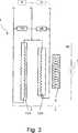
Die
Die Magnetanordnung
Der LTS-Bereich
In der gezeigten Ausführungsform sind die beiden (ersten) LTS-Sektionen
Der HTS-Bereich
Da der HTS-Bereich (die HTS-Spule)
- –
Der Hintergrundmagnet 2 wird abgekühlt und geladen, während die HTS-Spule 5 noch oberhalb ihrer Sprungtemperatur Tc,HTS gehalten wird. - –
Der Hintergrundmagnet 2 wird „überladen”, d. h. ein Strom wird eingestellt, der über dem nominellen Betriebsstrom IB1 liegt. Dies ist bei NMR-Magneten möglich, da im Allgemeinen der Betriebsstrom IB1 sehr viel niedriger als der kritische Strom Ic gewählt wird, um die Magnetdrift klein zu halten. Während des Ladevorgangs ist dies allerdings nicht relevant. - – Nun wird die Temperatur der HTS-
Spule 5 abgesenkt, bis sie supraleitend ist. - – Der
Strom im Hintergrundmagnet 2 wird nun auf den Betriebsstrom IB1 abgesenkt. Dabei wird in der HTS-Spule 5 Strom induziert. Durch geeignete Auslegung der Magnetanordnung1 ist es möglich, dass das Magnetfeld B0 in der Bohrung bei diesem Vorgang zunimmt. - – Nun wird der Hauptschalter
8 geschlossen („Persistent Mode”).
- - The
background magnet 2 is cooled and charged while theHTS coil 5 is still kept above its critical temperature Tc, HTS . - - The
background magnet 2 is "overloaded", ie a current is set, which is above the nominal operating current IB1 . This is possible with NMR magnets, since in general the operating current IB1 is chosen to be much lower than the critical current Ic in order to keep the magnetic drift small. While charging, this is not relevant. - - Now the temperature of the
HTS coil 5 lowered until it is superconducting. - - The current in the
background magnet 2 is now lowered to the operating current IB1 . It is in theHTS coil 5 Induced current. By suitable design of themagnet arrangement 1 it is possible that the magnetic field B0 in the bore increases in this process. - - Now the main switch
8th closed ("Persistent Mode").
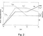
In
In einer ersten Phase zwischen t0 und t1 wird der Strom ILTS1 mit dem Netzgerät
Sodann wird zwischen t1 und t2 die Temperatur THTS des HTS-Bereichs
Schließlich wird zwischen t2 und t3 der Strom ILTS1 im LTS-Bereich
Sodann kann der supraleitende Schalter
Optimierung durch selektives Laden/Entladen bestimmter Sektionen, insbesondere Laden unter Verwendung der AbschirmsektionOptimization by selective loading / unloading of certain sections, in particular loading using the shielding section
im Hintergrundmagnet kann eine Spulensektion vom Restmagnet unabhängig geladen werden. Dazu sind eine zusätzliche Stromzuführung, ein zusätzliches Netzgerät und ein zusätzlicher supraleitender Schalter notwendig.In the background magnet, a coil section can be charged independently of the residual magnet. This requires an additional power supply, an additional power supply and an additional superconducting switch.
Die LTS-Spulensektion, die unabhängig geladen werden kann, kann dann so gewählt werden, dass die Kopplung mit der HTS-Spule optimal wird. Auch besteht die Möglichkeit, diese LTS-Spulensektion mit einem Notch auszuführen, und damit am Ende des Ladevorgangs die Homogenität des Magnetfelds B0 im Messvolumen abzustimmen.The LTS coil section, which can be charged independently, can then be chosen so that the coupling with the HTS coil becomes optimal. It is also possible to carry out this LTS coil section with a notch, and thus to tune the homogeneity of the magnetic field B0 in the measuring volume at the end of the charging process.
Im Besonderen ist zum induktiven Laden die LTS-Abschirmsektion (die üblicherweise zur Reduktion des Streufelds eingebaut wird) geeignet, da diese mit negativer Kopplungsinduktivität mit der HTS-Spule koppelt.In particular, for inductive charging, the LTS shielding section (which is commonly incorporated to reduce the stray field) is suitable because it couples with negative coupling inductance with the HTS coil.
Die
Der LTS-Bereich
Das Laden erfolgt dann beispielhaft nach folgendem Schema:
- – Der Hintergrundmagnet
2 (bestehend aus Hauptspule4 und Abschirmspule3 ) wird abgekühlt, während die HTS-Spule 5 noch oberhalb von Tc,HTS gehalten wird. - –
Nur die Hauptspule 4 desHintergrundmagneten 2 wird geladen, und für den Rest des Ladevorgangsmit dem Netzgerät 13 auf konstantem Strom gehalten.Das andere Netzgerät 9 hält in diesem Schritt die LTS-Abschirmsektion 3 stromlos. - –
Die Abschirmspule 3 wird in die „falsche” Richtung geladen, d. h. das Streufeld vergrößert sich zusätzlich, und das Magnetfeld B0 in der Bohrung nimmt leicht zu (ohne die feldreduzierende Wirkung der Abschirmspule3 wird dieHauptspule 4 überlastet; hier gilt aber das Argument von oben bzgl. des Betriebsstroms). - – Nun wird die Temperatur THTS der HTS-
Spule 5 abgesenkt, bis sie supraleitend ist. - – Die LTS-
Abschirmsektion 3 wird nun wieder entladen, und dann in die „richtige” Richtung geladen. Dabei schrumpft das Streufeld auf seinen Sollwert. Aufgrund des negativen Kopplungskoeffizienten nimmt bei dieser Stromänderung in der LTS-Abschirmsektion 3 auch der Strom in der HTS-Spule 5 zu. Während dieses Vorgangshält das Netzgerät 13 dieHauptspule 4 bei konstantem Strom und das Magnetfeld B0 in der Bohrung nimmt weiter zu. - – Nun werden alle supraleitenden
Schalter 14a ,14b geschlossen („Persistent Mode”).
- - The background magnet
2 (consisting ofmain coil 4 and shielding coil3 ) is cooled while theHTS coil 5 is still held above Tc, HTS . - - Only the
main coil 4 of thebackground magnet 2 is charged, and for the remainder of the charging process with thepower supply 13 kept at a constant current. Theother power supply 9 Holds the LTS shielding section in thisstep 3 de-energized. - - The
shielding coil 3 is charged in the "wrong" direction, ie, the stray field increases in addition, and the magnetic field B0 in the bore increases slightly (without the field-reducing effect of the shieldingcoil 3 becomes themain coil 4 overloaded; here, however, the argument from above regarding the operating current applies). - - Now the temperature THTS of the
HTS coil 5 lowered until it is superconducting. - - The
LTS shielding section 3 is now discharged again, and then loaded in the "right" direction. The stray field shrinks to its setpoint. Due to the negative coupling coefficient, this current change in the LTS shielding section decreases3 also the current in theHTS coil 5 to. During this process, the power supply stops13 themain coil 4 at constant current and the magnetic field B0 in the hole continues to increase. - - Now all
superconducting switches 14a .14b closed ("Persistent Mode").
In
In einer ersten Phase zwischen t0 und t1 wird der Strom ILTS2 in der zweiten LTS-Sektion
In einer zweiten Phase zwischen t1 und t2 wird nun der Strom ILTS1 in der ersten LTS-Sektion
Sodann wird zwischen t2 und t3 die Temperatur THTS des HTS-Bereichs
Schließlich wird zwischen t3 und t4 der Strom ILTS1 in der ersten LTS-Sektion
Sodann können die supraleitenden Schalter
Unabhängige Temperierung der HTS-SpuleIndependent tempering of the HTS coil
Für die (zumindest beim Laden) vom Hintergrundmagneten unabhängige Temperierung der HTS-Spule bestehen verschiedene Möglichkeiten. Im Allgemeinen und im Besonderen bei allen im Folgenden vorgestellten Ausführungsformen ist es vorteilhaft, einen Heizer an der HTS-Spule (oder im Tank, in dem die HTS-Spule angeordnet ist) anzubringen, um die Temperatur der HTS-Spule schnell anheben zu können oder auf einem bezüglich der Umgebung höheren Temperaturniveau zu halten.For the (at least when charging) independent of the background magnet tempering of the HTS coil there are various possibilities. In general, and in particular in all the embodiments presented below, it is advantageous to attach a heater to the HTS coil (or in the tank in which the HTS coil is arranged) in order to raise the temperature of the HTS coil quickly or to keep at a higher temperature level with respect to the environment.
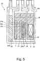
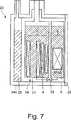
Wie in
In der gezeigten Ausführungsform umfasst die LTS-Spule (der LTS-Bereich)
Beide Heliumtanks
In der gezeigten Ausführungsform von
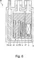
In einer alternativen Ausführungsform, die in
Weiterhin kann, wie in
Bei einer Ausführungsform eines Kryostaten
HTS-SpulenHTS coils
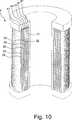
Bevorzugt wird zur Herstellung einer HTS-Spule bzw. HTS-Sektion HTS-Material – im Speziellen YBCO – mittels Dünnfilmabscheidung ringförmig auf zylindrisches Substratmaterial („Trägerkörper”) aufgebracht. Als Substratmaterial wird bevorzugt Hastelloy verwendet. Mit Hilfe von Laserstrukturierung kann ein zunächst durchgehender, abgeschiedener HTS-Zylindermantel in mehrere koaxiale, nebeneinanderliegende Ringe geteilt werden. Die Fabrikation von „Spulen” (es handelt sich ja eigentlich um eine Ansammlung von Ringen) kann auch mehrlagig erfolgen (d. h. gefertigt werden mehrere koaxiale Ringe oder Ringelagen mit größer werdenden Radien). Dabei kommt bevorzugt SrTiO3 als Isolator radial zwischen den Ringen oder Ringelagen zur Anwendung.For producing an HTS coil or HTS section, it is preferable to apply HTS material-in particular YBCO-by means of thin-film deposition in an annular manner onto a cylindrical substrate material ("carrier body"). Hastelloy is preferably used as the substrate material. With the help of laser structuring, an initially continuous, separated HTS cylinder jacket can be divided into several coaxial, juxtaposed rings. The fabrication of "coils" (this is actually an accumulation of rings) can also take place in multiple layers (ie several coaxial rings or ring layers are made with increasing radii). SrTiO3 is preferably used as insulator radially between the rings or ring layers.
Eine auf diese Art gefertigte Spule kann auch für den Bau eines Hochfeld-NMR Magneten verwendet werden. Da die HTS-Ringe durchgehend sind, entfällt die Notwendigkeit, supraleitende Verbindungen zwischen HTS-Leitern herzustellen. Die HTS-Ringe können geometrisch so geformt werden, dass sie ausreichend dünn sind, um die Homogenität des Magnetfelds nicht negativ zu beeinflussen (äquivalent zur Filamentierung in NbTi oder Nb3Sn Drähten).A coil made in this way can also be used for the construction of a high-field NMR magnet. Since the HTS rings are continuous, there is no need to make superconducting connections between HTS conductors. The HTS rings can be geometrically shaped to be sufficiently thin so as not to adversely affect the homogeneity of the magnetic field (equivalent to filamentation in NbTi or Nb3 Sn wires).
Eine wie oben beschrieben gefertigte HTS-Spule wird elektrisch nicht in Serie mit dem Hintergrundmagneten (bestehend aus Haupt- und Abschirmspule) aus LTS verbunden; die Notwendigkeit, supraleitende HTS-LTS Verbindungen herzustellen, entfällt deshalb. Ebenso entfällt die Notwendigkeit, einen HTS-Bandleiter auf komplizierte Weise aus der Region des höchsten Magnetfelds herauszuführen.An HTS coil made as described above is not electrically connected in series with the background magnet (consisting of the main and shield coils) of LTS; the need to produce superconducting HTS-LTS compounds is therefore eliminated. Likewise, eliminating the need to bring out an HTS band conductor in a complicated manner from the region of the highest magnetic field.
Die
In der
Alternativ können auch HTS-Spulen oder HTS-Sektionen auf Basis von HTS-Bandleiter gefertigt werden. Der HTS-Bandleiter umfasst typischerweise ein bandförmiges, metallisches Substrat (etwa ein Stahlblechband), auf dem eine oder mehrere Pufferschichten (etwa aus MgO), eine HTS-Schicht (etwa aus YBCO) und gegebenenfalls Shunt- und/oder Schutzschichten (meist aus Cu oder Edelmetallen wie Ag, Au) abgeschieden sind.Alternatively, HTS coils or HTS sections based on HTS ribbon conductors can also be manufactured. The HTS strip conductor typically comprises a strip-shaped metallic substrate (such as a steel strip) on which one or more buffer layers (such as MgO), an HTS layer (such as YBCO) and optionally shunt and / or protective layers (usually made of Cu or precious metals such as Ag, Au) are deposited.
Die
BezugszeichenlisteLIST OF REFERENCE NUMBERS
- 11
- Magnetanordnungmagnet assembly
- 22
- LTS-Bereich (Hintergrundmagnet, LTS-Spule)LTS area (background magnet, LTS coil)
- 33
- LTS-Abschirmsektion (Abschirmspule)LTS shielding section (shielding coil)
- 44
- LTS-Hauptsektion (Hauptspule)LTS main section (main coil)
- 5 5
- HTS-Bereich (HTS-Spule)HTS area (HTS coil)
- 66
- HTS-SektionHTS section
- 77
- Messvolumenmeasuring volume
- 88th
- supraleitender Schalter (Hauptschalter)superconducting switch (main switch)
- 99
- Netzgerätpower Supply
- 1111
- erste LTS-Sektionfirst LTS section
- 1212
- zweite LTS-Sektionsecond LTS section
- 1313
- Netzgerätpower Supply
- 14a, 14b14a, 14b
- supraleitende Schaltersuperconducting switches
- 2020
- Kryostatcryostat
- 2121
- erster Heliumtankfirst helium tank
- 2222
- zweiter Heliumtanksecond helium tank
- 23a–23c23a-23c
- UnterspulensektionenUnder coil sections
- 2424
- Vakuumtank (Vakuumbehälter)Vacuum tank (vacuum tank)
- 24a24a
- Wand des VakuumtanksWall of the vacuum tank
- 24b24b
- Vakuumraumvacuum space
- 2525
- äußerer Tank für flüssigen Stickstoff (LN2)outer liquid nitrogen tank (LN2)
- 25a25a
- Strahlungsschild des äußeren Tanks für flüssigen StickstoffRadiation shield of the outer tank for liquid nitrogen
- 2626
- RaumtemperaturbohrungRoom temperature bore
- 2727
- Strahlungsschild zwischen den HeliumtanksRadiation shield between the helium tanks
- 2828
- VentilValve
- 2929
- elektrischer Heizerelectric heater
- 3030
- Wärmeschalterthermal switch
- 3131
- zylindrischer Trägerkörper (Spulenträger)cylindrical carrier body (coil carrier)
- 3232
- Ring aus HTS-MaterialRing made of HTS material
- 3333
- innere Lageinner situation
- 3434
- äußere Lageouter location
- 3535
- Ende des geschlitzten HTS-BandleitersEnd of the slotted HTS tape conductor
- 3636
- HTS-HTS-JointHTS HTS joint
- 3737
- HTS-BandleiterHTS coated conductors
- 3838
- HTS-ZylindermantelHTS cylinder jacket
- 3939
- Isolationsschichtinsulation layer
- 4040
- Endscheibeend disk
- 4141
- radiale Lageradial position
- B0B0
- Magnetfeld im Messvolumen, in Richtung der SpulenachseMagnetic field in the measuring volume, in the direction of the coil axis
- IB1IB1
- erster Betriebsstromfirst operating current
- IB2IB2
- zweiter Betriebsstromsecond operating current
- IINIIN
- InterimstromInterim current
- ILTS1ILTS1
- Strom in der wenigstens einen ersten LTS-SektionCurrent in the at least one first LTS section
- ILTS2ILTS2
- Strom in der wenigstens einen zweiten LTS-SektionCurrent in the at least one second LTS section
- SASA
- Spulenachsecoil axis
- t0–t4t0-t4
- Zeitpunktetimings
- T1, T2, T3T1, T2, T3
- Stromzuführungen (Ladeanschlüsse)Power supply lines (charging connections)
- THTSTHTS
- Temperatur des HTS-BereichsTemperature of the HTS area
- Tc,HTSTc, HTS
- Sprungtemperatur des HTS-BereichsTransition temperature of the HTS area
- TLTSTLTS
- Temperatur des LTS-BereichsTemperature of the LTS area
- Tc,LTSTc, LTS
- Sprungtemperatur des LTS-BereichsTransition temperature of the LTS area
ZITATE ENTHALTEN IN DER BESCHREIBUNG QUOTES INCLUDE IN THE DESCRIPTION
Diese Liste der vom Anmelder aufgeführten Dokumente wurde automatisiert erzeugt und ist ausschließlich zur besseren Information des Lesers aufgenommen. Die Liste ist nicht Bestandteil der deutschen Patent- bzw. Gebrauchsmusteranmeldung. Das DPMA übernimmt keinerlei Haftung für etwaige Fehler oder Auslassungen.This list of the documents listed by the applicant has been generated automatically and is included solely for the better information of the reader. The list is not part of the German patent or utility model application. The DPMA assumes no liability for any errors or omissions.
Zitierte PatentliteraturCited patent literature
- DE 102006012508 B3[0002, 0007, 0014]DE 102006012508 B3[0002, 0007, 0014]
- DE 102006012509 B3[0007]DE 102006012509 B3[0007]
- DE 102006012511 B3[0007]DE 102006012511 B3[0007]
- DE 10033869 A1[0010]DE 10033869 A1[0010]
- US 6489769 B2[0011]US 6489769 B2[0011]
- US 6545474 B2[0011]US 6545474 B2[0011]
- US 8061016 B2[0012, 0029]US Pat. No. 8061016 B2[0012, 0029]
- EP 1604377 B1[0012, 0029]EP 1604377 B1[0012, 0029]
- DE 102011082652 A1[0101]DE 102011082652 A1[0101]
Zitierte Nicht-PatentliteraturCited non-patent literature
- Maher et al., Supercond. Sci. Tech. 17 (2004), 1440–1445[0012]Maher et al., Supercond. Sci. Tech. 17 (2004), 1440-1445[0012]
- Kim et al., IEEE TRANSACTIONS ON APPLIED SUPERCONDUCTIVITY, Vol. 19, No. 3, Juni 2009, Seiten 2273–2276[0013]Kim et al., IEEE TRANSACTIONS ON APPLIED SUPERCONDUCTIVITY, Vol. 3, June 2009, pages 2273-2276[0013]
Claims (20)
Translated fromGermanPriority Applications (4)
| Application Number | Priority Date | Filing Date | Title |
|---|---|---|---|
| DE102015218019.0ADE102015218019B4 (en) | 2015-09-18 | 2015-09-18 | A magnetostrated cryostat comprising an LTS region and an HTS region |
| GB1615610.1AGB2542940B (en) | 2015-09-18 | 2016-09-14 | Cryostat with magnet arrangement which includes an LTS portion and an HTS portion |
| JP2016180820AJP6636405B2 (en) | 2015-09-18 | 2016-09-15 | Cryostat with magnet device having LTS part and HTS part |
| US15/267,667US9766311B2 (en) | 2015-09-18 | 2016-09-16 | Cryostat with magnet arrangement which includes an LTS portion and an HTS portion |
Applications Claiming Priority (1)
| Application Number | Priority Date | Filing Date | Title |
|---|---|---|---|
| DE102015218019.0ADE102015218019B4 (en) | 2015-09-18 | 2015-09-18 | A magnetostrated cryostat comprising an LTS region and an HTS region |
Publications (2)
| Publication Number | Publication Date |
|---|---|
| DE102015218019A1true DE102015218019A1 (en) | 2017-03-23 |
| DE102015218019B4 DE102015218019B4 (en) | 2019-02-28 |
Family
ID=57234704
Family Applications (1)
| Application Number | Title | Priority Date | Filing Date |
|---|---|---|---|
| DE102015218019.0AActiveDE102015218019B4 (en) | 2015-09-18 | 2015-09-18 | A magnetostrated cryostat comprising an LTS region and an HTS region |
Country Status (4)
| Country | Link |
|---|---|
| US (1) | US9766311B2 (en) |
| JP (1) | JP6636405B2 (en) |
| DE (1) | DE102015218019B4 (en) |
| GB (1) | GB2542940B (en) |
Cited By (2)
| Publication number | Priority date | Publication date | Assignee | Title |
|---|---|---|---|---|
| DE102018221322A1 (en) | 2018-12-10 | 2020-06-10 | Bruker Switzerland Ag | Method for loading an HTS shim device and magnet arrangement |
| EP3822992A1 (en) | 2019-11-14 | 2021-05-19 | Bruker Switzerland AG | Method for charging a superconductor magnet system, with a main superconductor bulk magnet and a shield superconductor bulk magnet |
Families Citing this family (4)
| Publication number | Priority date | Publication date | Assignee | Title |
|---|---|---|---|---|
| GB2558685B8 (en)* | 2017-05-09 | 2019-04-10 | Univ Durham | Superconducting magnet for producing part of a substantially toroidal field |
| EP3496516B1 (en)* | 2017-12-11 | 2020-02-19 | Ion Beam Applications S.A. | Superconductor cyclotron regenerator |
| EP3910651B1 (en)* | 2020-05-14 | 2022-10-26 | Bruker Switzerland AG | Superconducting magnet system, with individual temperature control of axially stacked bulk sub-magnets |
| EP4390980A1 (en)* | 2022-12-22 | 2024-06-26 | Supernode Limited | A variable performance superconducting cable assembly |
Citations (10)
| Publication number | Priority date | Publication date | Assignee | Title |
|---|---|---|---|---|
| US5764121A (en)* | 1995-11-08 | 1998-06-09 | Intermagnetics General Corporation | Hybrid high field superconducting assembly and fabrication method |
| DE10033869A1 (en) | 2000-07-12 | 2002-01-31 | Karlsruhe Forschzent | HTS cryomagnet and magnetization process |
| US6489769B2 (en) | 2000-06-26 | 2002-12-03 | Riken | Nuclear magnetic resonance apparatus |
| US6545474B2 (en) | 2000-06-26 | 2003-04-08 | Riken | Controlling method of superconductor magnetic field application apparatus, and nuclear magnetic resonance apparatus and superconducting magnet apparatus using the method |
| DE102006012509B3 (en) | 2006-03-18 | 2007-10-04 | Bruker Biospin Gmbh | Cryostat with a magnetic coil system comprising an LTS and an arranged in the vacuum HTS section |
| DE102006012508B3 (en) | 2006-03-18 | 2007-10-18 | Bruker Biospin Gmbh | Cryostat with a magnetic coil system comprising an LTS and an encapsulated HTS section |
| DE102006012511B3 (en) | 2006-03-18 | 2007-11-22 | Bruker Biospin Gmbh | Cryostat with a magnetic coil system comprising a supercooled LTS and a HTS section arranged in a separate helium tank |
| EP1604377B1 (en) | 2003-03-06 | 2009-10-14 | 3-Cs Ltd. | Superconducting coil testing |
| US8061016B2 (en) | 2001-08-24 | 2011-11-22 | 3-Cs Ltd | Superconducting coil fabrication |
| DE102011082652A1 (en) | 2011-09-14 | 2013-03-14 | Bruker Biospin Ag | Method for producing a magnet coil arrangement from a slotted band-shaped conductor |
Family Cites Families (19)
| Publication number | Priority date | Publication date | Assignee | Title |
|---|---|---|---|---|
| US5596303A (en)* | 1993-02-22 | 1997-01-21 | Akguen Ali | Superconductive magnet system with low and high temperature superconductors |
| JP3737895B2 (en)* | 1998-11-16 | 2006-01-25 | 株式会社神戸製鋼所 | Permanent current superconducting magnet system |
| US7002341B2 (en)* | 2002-08-28 | 2006-02-21 | Vanderbilt University | Superconducting quantum interference apparatus and method for high resolution imaging of samples |
| US7859264B2 (en)* | 2004-01-20 | 2010-12-28 | The University Of Houston | Superconducting loop, saddle and birdcage MRI coils capable of simultaneously imaging small nonhuman animals |
| DE102004007340B4 (en)* | 2004-02-16 | 2008-10-16 | Bruker Biospin Gmbh | Low drift superconducting high field magnet system and high resolution magnetic resonance spectrometer |
| GB0508890D0 (en)* | 2005-04-29 | 2005-06-08 | Oxford Instr Plc | Magnetic resonance apparatus and method |
| US20100267567A1 (en)* | 2007-12-10 | 2010-10-21 | Koninklijke Philips Electronics N.V. | Superconducting magnet system with cooling system |
| GB2468359B (en)* | 2009-03-06 | 2013-09-11 | 3 Cs Ltd | Magnetic resonance system |
| US8253416B2 (en)* | 2009-03-10 | 2012-08-28 | Time Medical Holdings Company Limited | Superconductor magnetic resonance imaging system and method (super-MRI) |
| CN101577165B (en)* | 2009-03-20 | 2011-01-12 | 中国科学院电工研究所 | Superconducting magnet system with interpolated YBCO-Bitter high temperature superconducting coil |
| WO2013063257A1 (en)* | 2011-10-25 | 2013-05-02 | Massachusetts Institute Of Technology | Persistent-mode high-temperature superconducting shim coils to enhance spatial magnetic field homogeneity for superconducting magnets |
| GB201208838D0 (en)* | 2012-05-18 | 2012-07-04 | Oxford Instr Nanotechnology Tools Ltd | Apparatus for reducing noise in a cryocooler |
| JP2013251516A (en)* | 2012-06-04 | 2013-12-12 | Hitachi Ltd | Superconducting magnet device |
| DE102012215507B3 (en)* | 2012-08-31 | 2013-12-05 | Bruker Biospin Gmbh | Magnet arrangement for generating a highly stable magnetic field |
| RU2655474C2 (en)* | 2013-06-17 | 2018-05-28 | Конинклейке Филипс Н.В. | Magnetic resonance imaging gradient coil |
| DE102013220142A1 (en)* | 2013-10-04 | 2015-04-09 | Bruker Biospin Gmbh | Magnetic coil assembly comprising a HTSC ribbon conductor and an LTS wire forming a joint |
| DE102013220141B4 (en)* | 2013-10-04 | 2017-11-16 | Bruker Biospin Gmbh | An NMR spectrometer comprising a superconducting magnet coil with windings of a superconductor structure with chained band pieces, which are each overlapped by immediately successive, further band pieces |
| US10184711B2 (en)* | 2014-05-19 | 2019-01-22 | General Electric Company | Cryogenic cooling system |
| US10222432B2 (en)* | 2014-06-17 | 2019-03-05 | Quantum Valley Investment Fund LP | Birdcage resonator for magnetic resonance |
- 2015
- 2015-09-18DEDE102015218019.0Apatent/DE102015218019B4/enactiveActive
- 2016
- 2016-09-14GBGB1615610.1Apatent/GB2542940B/enactiveActive
- 2016-09-15JPJP2016180820Apatent/JP6636405B2/enactiveActive
- 2016-09-16USUS15/267,667patent/US9766311B2/enactiveActive
Patent Citations (10)
| Publication number | Priority date | Publication date | Assignee | Title |
|---|---|---|---|---|
| US5764121A (en)* | 1995-11-08 | 1998-06-09 | Intermagnetics General Corporation | Hybrid high field superconducting assembly and fabrication method |
| US6489769B2 (en) | 2000-06-26 | 2002-12-03 | Riken | Nuclear magnetic resonance apparatus |
| US6545474B2 (en) | 2000-06-26 | 2003-04-08 | Riken | Controlling method of superconductor magnetic field application apparatus, and nuclear magnetic resonance apparatus and superconducting magnet apparatus using the method |
| DE10033869A1 (en) | 2000-07-12 | 2002-01-31 | Karlsruhe Forschzent | HTS cryomagnet and magnetization process |
| US8061016B2 (en) | 2001-08-24 | 2011-11-22 | 3-Cs Ltd | Superconducting coil fabrication |
| EP1604377B1 (en) | 2003-03-06 | 2009-10-14 | 3-Cs Ltd. | Superconducting coil testing |
| DE102006012509B3 (en) | 2006-03-18 | 2007-10-04 | Bruker Biospin Gmbh | Cryostat with a magnetic coil system comprising an LTS and an arranged in the vacuum HTS section |
| DE102006012508B3 (en) | 2006-03-18 | 2007-10-18 | Bruker Biospin Gmbh | Cryostat with a magnetic coil system comprising an LTS and an encapsulated HTS section |
| DE102006012511B3 (en) | 2006-03-18 | 2007-11-22 | Bruker Biospin Gmbh | Cryostat with a magnetic coil system comprising a supercooled LTS and a HTS section arranged in a separate helium tank |
| DE102011082652A1 (en) | 2011-09-14 | 2013-03-14 | Bruker Biospin Ag | Method for producing a magnet coil arrangement from a slotted band-shaped conductor |
Non-Patent Citations (4)
| Title |
|---|
| Kim et al., IEEE TRANSACTIONS ON APPLIED SUPERCONDUCTIVITY, Vol. 19, No. 3, Juni 2009, Seiten 2273–2276 |
| KIM, SeokBeom [u.a.]: Study on Trapped Field Characteristics of HTS Bulk Annuli With Iron Rings for Ferromagnetic Shimming of a Compact NMR Magnet. In: IEEE Transactions on Applied Superconductivity (T-ASC). Juni 2009, Bd. 19, H. 3, S. 2273-2276. - E-ISSN: 1558-2515 P-ISSN: 1051-8223* |
| Maher et al., Supercond. Sci. Tech. 17 (2004), 1440–1445 |
| MAHER, E [u. a.]: Multi-layer coated conductor cylinders - an alternative approach to superconducting coil fabrication. In: Superconductor Science and Technology. 2 November 2004, Bd.17, S. 1440-1445. - E-ISSN: 1361-6668 , P-ISSN: 0953-2048* |
Cited By (5)
| Publication number | Priority date | Publication date | Assignee | Title |
|---|---|---|---|---|
| DE102018221322A1 (en) | 2018-12-10 | 2020-06-10 | Bruker Switzerland Ag | Method for loading an HTS shim device and magnet arrangement |
| EP3667351A1 (en) | 2018-12-10 | 2020-06-17 | Bruker Switzerland AG | Method for charging an hts shim device and magnetic arrangement |
| US11393615B2 (en) | 2018-12-10 | 2022-07-19 | Bruker Switzerland Ag | Method for charging an HTS shim device and magnet arrangement |
| EP3822992A1 (en) | 2019-11-14 | 2021-05-19 | Bruker Switzerland AG | Method for charging a superconductor magnet system, with a main superconductor bulk magnet and a shield superconductor bulk magnet |
| US11527343B2 (en) | 2019-11-14 | 2022-12-13 | Bruker Switzerland Ag | Method for charging a superconductor magnet system, with a main superconductor bulk magnet and a shield superconductor bulk magnet |
Also Published As
| Publication number | Publication date |
|---|---|
| US20170082707A1 (en) | 2017-03-23 |
| GB2542940A (en) | 2017-04-05 |
| US9766311B2 (en) | 2017-09-19 |
| JP6636405B2 (en) | 2020-01-29 |
| DE102015218019B4 (en) | 2019-02-28 |
| JP2017069556A (en) | 2017-04-06 |
| GB201615610D0 (en) | 2016-10-26 |
| GB2542940B (en) | 2020-12-02 |
Similar Documents
| Publication | Publication Date | Title |
|---|---|---|
| DE102015218019B4 (en) | A magnetostrated cryostat comprising an LTS region and an HTS region | |
| DE102004007340B4 (en) | Low drift superconducting high field magnet system and high resolution magnetic resonance spectrometer | |
| EP2901460B1 (en) | Magnetic coil arrangement comprising a htsc band conductor and a ltsc wire, froming a joint | |
| EP0154779B1 (en) | Superconducting magnetic system for operation at 13k | |
| EP1999764B1 (en) | Cryostat having a magnet coil system, which comprises an undercooled lts section and an hts section arranged in a separate helium tank | |
| DE69128372T2 (en) | Magnet with active shielding. without kyrogenic refrigerants, for magnetic resonance | |
| WO2003098645A1 (en) | Superconductor technology-related device comprising a superconducting magnet and a cooling unit | |
| DE102010042598A1 (en) | Superconductive magnetic resonance-magnet arrangement for use in magnetic resonance-magnet system, has slot dividing dual pancake coil into partial coils that are rotated and/or displaced with dual coil to produce spatial field pattern | |
| DE102005028414B4 (en) | Device for generating a pulsed magnetic field | |
| DE3900725C2 (en) | ||
| EP3336568B1 (en) | Magnet assembly with superconducting closed hts shims | |
| DE19947539A1 (en) | Gradient coil arrangement for magnetic resonance equipment, has pipe-shaped shielding cylinder connected firmly with gradient coil system or is an integral mechanical component of gradient coil system | |
| EP0485395A1 (en) | Superconducting homogeneous intense-field magnetic coil. | |
| EP0151719A2 (en) | Magnetic system for a nuclear magnetic resonance tomograph | |
| EP2985769A1 (en) | Method for charging a superconducting magnet assembly with power | |
| DE102015210655A1 (en) | Electric coil device for inductive-resistive current limiting | |
| CH649647A5 (en) | SUPERCONDUCTIVE COIL FOR A NUCLEAR RESON. | |
| DE102014224363A1 (en) | Device of superconducting technology with coil devices and cooling device as well as vehicle equipped therewith | |
| WO2020038909A1 (en) | Rotor with superconducting winding for continuous current mode operation | |
| DE102014217250A1 (en) | Superconducting coil device with switchable conductor section and method for switching | |
| EP3889633B1 (en) | Shim device having a high temperature superconducting shim conductor track, a magnet arrangement and a method of loading an hts shim device | |
| DE102017217930A1 (en) | Magnet arrangement with cryostat and magnetic coil system, with cold accumulators on the power supply lines | |
| EP0013399A1 (en) | Cooling device for superconducting magnet coil | |
| DE102018218473A1 (en) | Rotor, machine and method for magnetizing | |
| DE102015208470A1 (en) | Electric coil device for current limitation |
Legal Events
| Date | Code | Title | Description |
|---|---|---|---|
| R012 | Request for examination validly filed | ||
| R016 | Response to examination communication | ||
| R016 | Response to examination communication | ||
| R018 | Grant decision by examination section/examining division | ||
| R020 | Patent grant now final | ||
| R081 | Change of applicant/patentee | Owner name:BRUKER BIOSPIN GMBH & CO. KG, DE Free format text:FORMER OWNER: BRUKER BIOSPIN GMBH, 76287 RHEINSTETTEN, DE |