DE102015212857A1 - Adjusting device and method for adjusting the center position of a steering wheel of a vehicle - Google Patents
Adjusting device and method for adjusting the center position of a steering wheel of a vehicleDownload PDFInfo
- Publication number
- DE102015212857A1 DE102015212857A1DE102015212857.1ADE102015212857ADE102015212857A1DE 102015212857 A1DE102015212857 A1DE 102015212857A1DE 102015212857 ADE102015212857 ADE 102015212857ADE 102015212857 A1DE102015212857 A1DE 102015212857A1
- Authority
- DE
- Germany
- Prior art keywords
- segment
- tube segment
- adjustment
- outer tube
- adjusting
- Prior art date
- Legal status (The legal status is an assumption and is not a legal conclusion. Google has not performed a legal analysis and makes no representation as to the accuracy of the status listed.)
- Granted
Links
- 238000000034methodMethods0.000titleclaimsabstractdescription12
- 230000033001locomotionEffects0.000claimsdescription45
- 210000001331noseAnatomy0.000description8
- 238000004519manufacturing processMethods0.000description5
- 238000006073displacement reactionMethods0.000description4
- 239000000463materialSubstances0.000description4
- 210000003128headAnatomy0.000description3
- 230000005540biological transmissionEffects0.000description2
- 230000008878couplingEffects0.000description2
- 238000010168coupling processMethods0.000description2
- 238000005859coupling reactionMethods0.000description2
- 239000007787solidSubstances0.000description2
- 230000002411adverseEffects0.000description1
- 230000009286beneficial effectEffects0.000description1
- 238000010276constructionMethods0.000description1
- 230000001419dependent effectEffects0.000description1
- 230000000694effectsEffects0.000description1
- 238000003780insertionMethods0.000description1
- 230000037431insertionEffects0.000description1
- 238000009434installationMethods0.000description1
- 230000003134recirculating effectEffects0.000description1
- 238000000926separation methodMethods0.000description1
Images


Classifications
- B—PERFORMING OPERATIONS; TRANSPORTING
- B62—LAND VEHICLES FOR TRAVELLING OTHERWISE THAN ON RAILS
- B62D—MOTOR VEHICLES; TRAILERS
- B62D1/00—Steering controls, i.e. means for initiating a change of direction of the vehicle
- B62D1/02—Steering controls, i.e. means for initiating a change of direction of the vehicle vehicle-mounted
- B62D1/16—Steering columns
- B62D1/20—Connecting steering column to steering gear
- B—PERFORMING OPERATIONS; TRANSPORTING
- B62—LAND VEHICLES FOR TRAVELLING OTHERWISE THAN ON RAILS
- B62D—MOTOR VEHICLES; TRAILERS
- B62D1/00—Steering controls, i.e. means for initiating a change of direction of the vehicle
- B62D1/02—Steering controls, i.e. means for initiating a change of direction of the vehicle vehicle-mounted
- B62D1/16—Steering columns
- F—MECHANICAL ENGINEERING; LIGHTING; HEATING; WEAPONS; BLASTING
- F16—ENGINEERING ELEMENTS AND UNITS; GENERAL MEASURES FOR PRODUCING AND MAINTAINING EFFECTIVE FUNCTIONING OF MACHINES OR INSTALLATIONS; THERMAL INSULATION IN GENERAL
- F16D—COUPLINGS FOR TRANSMITTING ROTATION; CLUTCHES; BRAKES
- F16D1/00—Couplings for rigidly connecting two coaxial shafts or other movable machine elements
- F16D1/10—Quick-acting couplings in which the parts are connected by simply bringing them together axially
- F16D1/108—Quick-acting couplings in which the parts are connected by simply bringing them together axially having retaining means rotating with the coupling and acting by interengaging parts, i.e. positive coupling
- F—MECHANICAL ENGINEERING; LIGHTING; HEATING; WEAPONS; BLASTING
- F16—ENGINEERING ELEMENTS AND UNITS; GENERAL MEASURES FOR PRODUCING AND MAINTAINING EFFECTIVE FUNCTIONING OF MACHINES OR INSTALLATIONS; THERMAL INSULATION IN GENERAL
- F16D—COUPLINGS FOR TRANSMITTING ROTATION; CLUTCHES; BRAKES
- F16D1/00—Couplings for rigidly connecting two coaxial shafts or other movable machine elements
- F16D1/12—Couplings for rigidly connecting two coaxial shafts or other movable machine elements allowing adjustment of the parts about the axis
- F—MECHANICAL ENGINEERING; LIGHTING; HEATING; WEAPONS; BLASTING
- F16—ENGINEERING ELEMENTS AND UNITS; GENERAL MEASURES FOR PRODUCING AND MAINTAINING EFFECTIVE FUNCTIONING OF MACHINES OR INSTALLATIONS; THERMAL INSULATION IN GENERAL
- F16D—COUPLINGS FOR TRANSMITTING ROTATION; CLUTCHES; BRAKES
- F16D3/00—Yielding couplings, i.e. with means permitting movement between the connected parts during the drive
- F16D3/02—Yielding couplings, i.e. with means permitting movement between the connected parts during the drive adapted to specific functions
- F16D3/06—Yielding couplings, i.e. with means permitting movement between the connected parts during the drive adapted to specific functions specially adapted to allow axial displacement
- F—MECHANICAL ENGINEERING; LIGHTING; HEATING; WEAPONS; BLASTING
- F16—ENGINEERING ELEMENTS AND UNITS; GENERAL MEASURES FOR PRODUCING AND MAINTAINING EFFECTIVE FUNCTIONING OF MACHINES OR INSTALLATIONS; THERMAL INSULATION IN GENERAL
- F16D—COUPLINGS FOR TRANSMITTING ROTATION; CLUTCHES; BRAKES
- F16D3/00—Yielding couplings, i.e. with means permitting movement between the connected parts during the drive
- F16D3/16—Universal joints in which flexibility is produced by means of pivots or sliding or rolling connecting parts
- F16D3/26—Hooke's joints or other joints with an equivalent intermediate member to which each coupling part is pivotally or slidably connected
- F16D3/38—Hooke's joints or other joints with an equivalent intermediate member to which each coupling part is pivotally or slidably connected with a single intermediate member with trunnions or bearings arranged on two axes perpendicular to one another
- F16D3/382—Hooke's joints or other joints with an equivalent intermediate member to which each coupling part is pivotally or slidably connected with a single intermediate member with trunnions or bearings arranged on two axes perpendicular to one another constructional details of other than the intermediate member
- F16D3/387—Fork construction; Mounting of fork on shaft; Adapting shaft for mounting of fork
Landscapes
- Engineering & Computer Science (AREA)
- General Engineering & Computer Science (AREA)
- Mechanical Engineering (AREA)
- Chemical & Material Sciences (AREA)
- Combustion & Propulsion (AREA)
- Transportation (AREA)
- Steering Controls (AREA)
Abstract
Translated fromGermanDescription
Translated fromGermanDie vorliegende Erfindung betrifft eine Justierungsvorrichtung sowie ein Verfahren zum Justieren eines Lenkwinkels eines Lenkrades eines Fahrzeuges. Ferner betrifft die vorliegende Erfindung eine Lenkung eines Fahrzeuges, aufweisend wenigstens eine Justierungsvorrichtung sowie ein mit der Justierungsvorrichtung wirkverbundenes Lenkrad und ein mit der Justierungsvorrichtung wirkverbundenes Lenkgetriebe.The present invention relates to an adjustment device and a method for adjusting a steering angle of a steering wheel of a vehicle. Furthermore, the present invention relates to a steering of a vehicle, comprising at least one adjusting device and a steering wheel operatively connected to the adjusting device and a steering gear operatively connected to the adjusting device.
Grundlegend ist es bekannt, dass nach der Herstellung eines Fahrzeuges und insbesondere der Montage des Fahrzeuges sowie auch nach einem Setzen von Verschraubungen im Lenkgetriebe beim Endkunden eine Schiefstellung des Lenkrades nachteilig erfolgen kann. Die Schiefstellung des Lenkrades wird insbesondere durch gerade Sichtkanten im Hintergrund des Lenkrades, wie beispielsweise durch die Sichtkanten des Armaturenbrettes, sowie auch aufgrund gerader Kanten am Lenkrad selbst optisch verstärkt. Unter einer Lenkradschiefstellung wird insbesondere ein nach rechts oder nach links verdrehtes Lenkrad bei einer beabsichtigten Geradeausfahrt des Fahrzeuges verstanden. Vorteilhaft besteht bei Kraftfahrzeugen bzw. Fahrzeugen das Bedürfnis, ein Lenkrad derart anzuordnen, dass es möglichst genau mittig ausgerichtet ist, wenn das Fahrzeug selbst geradeaus fahren soll. Ein von der Mittellage abweichend ausgerichtetes Lenkrad weist folglich eine Lenkradschiefstellung auf und stört den Fahrzeugführer beim Lenken des Fahrzeuges. Die Lenkradschiefstellung kann nachteilig zur Einschränkung im Fahrverhalten des Fahrzeugführers und folglich zu einem Unfall beim Fahren des Fahrzeuges führen. Insbesondere bei der Montage des Kraftfahrzeuges und insbesondere des Lenksystems können sich unterschiedliche Herstellungstoleranzen von lenkbaren Fahrzeugrädern über beispielsweise das Lenkgestänge, das Lenkgetriebe, die Lenkspindel und das Lenkrad und so weiter aufaddieren, wodurch eine Schiefstellung des Lenkrades erzeugt werden kann. Grundlegend ist es bekannt, dass Lenkradschiefstellungen korrigiert werden können, wenn insbesondere der Winkelwert des Lenkradschiefstandes bekannt ist. Jedoch ist es bei der Montage der Fahrzeuge unüblich, das Fahrzeug selbst und folglich auch das Lenkrad zu bewegen. Meist stehen die Fahrzeuge still und werden nur geradeaus über eine Transportvorrichtung bewegt, wobei der Lenkradwinkel nicht überprüfbar ist.Basically, it is known that after the production of a vehicle and in particular the assembly of the vehicle as well as after setting screwing in the steering gear at the end customer a misalignment of the steering wheel can be disadvantageous. The misalignment of the steering wheel is visually enhanced in particular by straight visible edges in the background of the steering wheel, such as by the visible edges of the dashboard, as well as due to straight edges on the steering wheel itself. Under a steering wheel misalignment in particular a right or left twisted steering wheel is understood in an intended straight ahead driving the vehicle. Advantageously, in motor vehicles or vehicles there is a need to arrange a steering wheel such that it is aligned as accurately as possible in the center, when the vehicle itself should drive straight ahead. A deviating from the center position steering wheel thus has a steering wheel misalignment and disturbs the driver when driving the vehicle. The steering wheel misalignment can adversely lead to the restriction in the driving behavior of the driver and thus to an accident while driving the vehicle. In particular, during assembly of the motor vehicle and in particular the steering system, different manufacturing tolerances of steerable vehicle wheels on, for example, the steering linkage, the steering gear, the steering shaft and the steering wheel and so on can add up, whereby a misalignment of the steering wheel can be generated. Basically, it is known that steering wheel misalignments can be corrected if, in particular, the angle value of the steering wheel angle is known. However, it is unusual in the assembly of the vehicles to move the vehicle itself and consequently also the steering wheel. Most of the vehicles are stationary and are only moved straight on a transport device, the steering wheel angle is not verifiable.
Es ist daher die Aufgabe der vorliegenden Erfindung, die voranstehend beschriebenen Nachteile der Lenkradschiefstellung eines Fahrzeuges zumindest teilweise zu beheben. Insbesondere ist es die Aufgabe der vorliegenden Erfindung, eine Vorrichtung und ein Verfahren zum Justieren eines Lenkwinkels eines Lenkrades eines Fahrzeuges zur Verfügung zu stellen, mittels welchen auf eine einfache und kostengünstige Art und Weise eine Lenkradschiefstellung eines Lenkrades eines Fahrzeuges behoben werden kann. Vorteilhaft soll die Lenkradschiefstellung manuell auch durch jeden Endbenutzer selbst behoben werden können.It is therefore the object of the present invention to remedy the above-described disadvantages of steering wheel misalignment of a vehicle at least partially. In particular, it is the object of the present invention to provide a device and a method for adjusting a steering angle of a steering wheel of a vehicle, by means of which a steering wheel misalignment of a steering wheel of a vehicle can be remedied in a simple and cost-effective manner. Advantageously, the steering wheel misalignment should be able to be manually corrected by each end user himself.
Die voranstehende Aufgabe wird gelöst durch eine Justierungsvorrichtung zum Justieren eines Lenkwinkels eines Lenkrades eines Fahrzeuges mit den Merkmalen gemäß Anspruch 1 sowie durch ein Verfahren zum Justieren eines Lenkwinkels eines Lenkrades eines Fahrzeuges mit den Merkmalen gemäß Anspruch 10. Ferner wird die voranstehende Aufgabe gelöst durch eine Lenkung eines Fahrzeuges mit den Merkmalen gemäß Anspruch 9. Weitere Merkmale und Details der Erfindung ergeben sich aus den Unteransprüchen, der Beschreibung und den Zeichnungen. Dabei gelten Merkmale und Details, die im Zusammenhang mit der Justierungsvorrichtung beschrieben sind, selbstverständlich auch im Zusammenhang mit dem erfindungsgemäßen Verfahren und/oder der erfindungsgemäßen Lenkung eines Fahrzeuges und jeweils umgekehrt, so dass bzgl. der Offenbarung zu den einzelnen Erfindungsaspekten stets wechselseitig Bezug genommen wird bzw. werden kann. Außerdem kann das erfindungsgemäße Verfahren mit der erfindungsgemäßen Justierungsvorrichtung durchgeführt werden.The above object is achieved by an adjusting device for adjusting a steering angle of a steering wheel of a vehicle with the features of
Die Justierungsvorrichtung zum Justieren eines Lenkwinkels eines Lenkrades eines Fahrzeuges weist wenigstens
- – ein Innenrohrsegment mit einem an einem distalen Ende des Innenrohrsegmentes angeordneten Befestigungselement zur Anordnung eines ersten Gelenkelementes,
- – ein Außenrohrsegment, welches am Innenrohrsegment angeordnet ist und zumindest einen sich von einer äußeren Oberfläche wegerstreckenden Vorsprung aufweist, und
- – ein Justierungssegment mit einem an einem distalen Ende des Justierungssegmentes angeordneten Befestigungselement zur Anordnung eines zweiten Gelenkelementes
- An inner tube segment having a fastening element arranged at a distal end of the inner tube segment for arranging a first joint element,
- An outer tube segment which is arranged on the inner tube segment and has at least one projection extending away from an outer surface, and
- - An adjustment segment with a arranged at a distal end of the adjustment segment fastener for arranging a second joint element
Erfindungsgemäß umgibt das Justierungssegment das Außenrohrsegment wenigstens abschnittsweise und weist wenigstens eine schräg zu einer Längsachse des Justierungssegmentes verlaufende Führungsnut zum Führen des Vorsprunges des Außenrohrsegmentes auf. Vorteilhaft ist die Justierungsvorrichtung ein Bestandteil einer Gelenkzwischenwelle bzw. bildet die Gelenkzwischenwelle. Die Gelenkzwischenwelle bzw. Lenkzwischenwelle und die Lenksäule eines Fahrzeuges stellen in ihrer Grundfunktion eine mechanische Kopplung zwischen dem Lenkrad und dem Lenkgetriebe her. Vorteilhaft werden dabei das Lenkrad und der Torsionsstab des Lenkgetriebes derart miteinander verbunden, dass die am Lenkrad eingeleitete Drehbewegung verlustfrei und ohne Spiel übertragen werden kann. Vorteilhaft werden zudem die vom Lenkgetriebe ausgehenden Drehmomente an das Lenkrad übertragen, so dass durch die Koppelglieder Lenksäule und Lenkzwischenwelle das Fahrverhalten und der spürbare Kontakt zum Fahrbahnuntergrund beeinflusst werden können. Vorteilhaft ermöglicht die Lenksäule zudem auch die Positionierung des Lenkrades gegenüber dem Fahrer. Hierbei wird in eine Neigungs- bzw. Höhen- und Längsverstellung unterschieden.According to the invention, the adjustment segment surrounds the outer tube segment at least in sections and has at least one guide groove running obliquely to a longitudinal axis of the adjustment segment for guiding the projection of the outer tube segment. Advantageously, the adjustment device is part of a joint intermediate shaft or forms the joint intermediate shaft. The joint intermediate shaft or steering intermediate shaft and the steering column of a vehicle in their basic function produce a mechanical coupling between the steering wheel and the steering gear. Advantageous In this case, the steering wheel and the torsion bar of the steering gear are connected to each other in such a way that the rotary motion introduced at the steering wheel can be transmitted losslessly and without play. Advantageously, the outgoing from the steering gear torques are transmitted to the steering wheel, so that the driving behavior and noticeable contact with the road surface can be influenced by the coupling elements steering column and steering intermediate shaft. Advantageously, the steering column also allows the positioning of the steering wheel relative to the driver. This distinction is made in a tilt or height and longitudinal adjustment.
Das Innenrohrsegment, welches erfindungsgemäß ein Bestandteil der Justierungsvorrichtung ist, ist vorteilhaft in Form eines Rohres bzw. eines Zylinders und vorteilhaft eines Vollzylinders ausgestaltet. An wenigstens einem distalen Ende des Innenrohrsegmentes, das bedeutet im Bereich einer Stirnwandung und vorteilhaft sich von der Stirnwandung des Innenrohsegmentes weg erstreckend, ist ein Befestigungselement angeordnet, welches beispielsweise in Form einer Vertiefung, einer Aussparung, eines kleiner dimensionierten (Kreis-)Segmentes oder in vergleichbarer Weise ausgestaltet sein kann. Mittels des Befestigungselementes, welches auch ein Befestigungsabschnitt sein kann, ist ein Gelenkelement, insbesondere das erste Gelenkelement, anordenbar bzw. fixierbar. Vorteilhaft wird das erste Gelenkelement derart mit dem distalen Ende des Innenrohrsegmentes verbunden, dass bei einer translatorischen sowie auch rotatorischen Bewegung des Innenrohrsegmentes entlang dessen Längsachse bzw. um dessen Längsachse herum auch das Gelenkelement selbst in translatorischer oder auch rotatorischer Richtung bewegt wird.The inner tube segment, which according to the invention is a component of the adjusting device, is advantageously designed in the form of a tube or a cylinder and advantageously a solid cylinder. At at least one distal end of the inner tube segment, which means extending in the region of an end wall and advantageously away from the end wall of the Innenrohsegmentes, a fastener is arranged, for example in the form of a recess, a recess, a smaller sized (circular) segment or in can be configured comparable way. By means of the fastening element, which can also be a fastening section, a joint element, in particular the first joint element, can be arranged or fixed. Advantageously, the first joint element is connected to the distal end of the inner tube segment in such a way that the articulation element itself is moved in a translatory or rotational direction in the case of a translatory and also rotational movement of the inner tube segment along its longitudinal axis or about its longitudinal axis.
Das Außenrohrsegment, welches am Innenrohrsegment angeordnet ist und vorzugsweise das Innenrohrsegment zumindest abschnittsweise umgibt, ist vorteilhaft in Form eines Rohres und insbesondere eines Hohlzylinders ausgestaltet. So ist es denkbar, dass das Außenrohrsegment das Innenrohrsegment zumindest abschnittsweise aufnimmt bzw. über das Innenrohrsegment gestülpt werden kann. Vorteilhaft sind das Innenrohrsegment und das Außenrohrsegment derart miteinander verbunden, dass eine translatorische Bewegung zwischen dem Außenrohrsegment und dem Innenrohrsegment ermöglicht wird, während eine rotatorische Bewegung insbesondere des Außenrohrsegmentes um das Innenrohrsegment bzw. des Innenrohrsegmentes innerhalb des Außenrohrsegmentes vermieden wird. Demzufolge wechselwirken das Innenrohrsegment und das Außenrohrsegment miteinander. Dies ist insbesondere dadurch von Vorteil, dass die Drehbewegung des Lenkrades über das Außenrohrsegment an das Innenrohrsegment übertragen bzw. weitergeleitet werden kann, wodurch eine entsprechende Lenkbewegung auf das Lenkgetriebe des Fahrzeugs übertragen wird. Das Innenrohrsegment und das Außenrohrsegment bilden demzufolge vorteilhaft ineinander verschiebbare stabförmige Segmente, welche vorteilhaft im Wesentlichen koaxial zueinander angeordnet sind und folglich eine gemeinsame Drehachse aufweisen. Innenrohrsegment und Außenrohrsegment können auch einstückig ausgestaltet sein. Das heißt Innenrohr- und Außenrohrsegment bilden eine Einheit, an der das erste Gelenkelement angeordnet und der wegerstreckende Vorsprung ausgebildet ist.The outer tube segment, which is arranged on the inner tube segment and preferably surrounds the inner tube segment at least in sections, is advantageously designed in the form of a tube and in particular a hollow cylinder. Thus, it is conceivable that the outer tube segment, the inner tube segment at least partially receives or can be slipped over the inner tube segment. Advantageously, the inner tube segment and the outer tube segment are connected to one another such that a translational movement between the outer tube segment and the inner tube segment is made possible, while a rotational movement in particular of the outer tube segment around the inner tube segment or of the inner tube segment within the outer tube segment is avoided. As a result, the inner tube segment and the outer tube segment interact with each other. This is particularly advantageous in that the rotational movement of the steering wheel can be transmitted via the outer tube segment to the inner tube segment or forwarded, whereby a corresponding steering movement is transmitted to the steering gear of the vehicle. The inner tube segment and the outer tube segment therefore advantageously form telescopic rod-shaped segments, which are advantageously arranged substantially coaxially to one another and consequently have a common axis of rotation. Inner tube segment and outer tube segment can also be configured in one piece. That is, inner tube and outer tube segments form a unit on which the first joint element is arranged and the wegerstreckende projection is formed.
Des Weiteren weist das Außenrohrsegment zumindest einen Vorsprung bzw. eine Nase oder auch eine Aufwölbung oder Vergleichbares auf, welche sich ausgehend von einer Außenseite und insbesondere einer äußeren Oberfläche des Außenrohrsegmentes von diesem Außenrohrsegment im Wesentlichen orthogonal zur Längsachse des Außenrohrsegmentes betrachtet, wegerstreckt. So ist es auch denkbar, dass das Außenrohrsegment mehr als einen derartigen Vorsprung aufweist und vorteilhaft zwei, drei oder auch vier derartige Vorsprünge aufweist. Bei einer Mehrzahl von Vorsprüngen sind diese im Wesentlichen in einem Abstand zueinander am Umfang des Außenrohrsegmentes in einer definierten Höhe und insbesondere einer gleichen Höhe, in Längsrichtung der Längsachse des Außenrohrsegmentes betrachtet, angeordnet.Furthermore, the outer tube segment on at least one projection or a nose or a bulge or the like, which, starting from an outer side and in particular an outer surface of the outer tube segment of this outer tube segment substantially orthogonal to the longitudinal axis of the outer tube segment, wegerstreckt. Thus, it is also conceivable that the outer tube segment has more than one such projection and advantageously has two, three or even four such projections. In the case of a plurality of projections, these are arranged substantially at a distance from each other on the circumference of the outer tube segment at a defined height and in particular at the same height, viewed in the longitudinal direction of the longitudinal axis of the outer tube segment.
Das Justierungssegment ist ein weiterer Bestandteil der Justierungsvorrichtung. Es weist an dessen distalen Ende bzw. an einem Endbereich, welcher im Wesentlichen einem Bereich an der Grundfläche oder der Deckfläche des zylinderförmigen Justierungssegmentes entspricht, ein Befestigungselement zur Anordnung eines zweiten Gelenkelementes auf. Das Befestigungselement des Justierungssegmentes kann vergleichbar zu dem Befestigungselement des Innenrohrsegmentes ausgestaltet sein. So ist es denkbar, dass das Befestigungselement selbst in Form einer Aussparung, einer Aufwölbung, eines Eingriffsbereichs, einer Klemmvorrichtung, einer Spannvorrichtung oder auch eines sich verjüngenden Absatzes oder in vergleichbarer Weise ausgestaltet ist, um insbesondere ein Aufbringen, wie beispielsweise ein Aufstecken, eines Gelenkelementes im Bereich des distalen Endes des Justierungssegmentes zu ermöglichen. So ist es möglich, dass das erste Gelenkelement auf das Befestigungselement des Innenrohrsegmentes sowie auch das zweite Gelenkelement auf das Befestigungselement des Justierungssegmentes aufgepresst wird, so dass insbesondere eine kraftschlüssige Verbindung zwischen dem jeweiligen Gelenkelement und dem Befestigungselement entsteht. Es ist des Weiteren auch denkbar, dass das Gelenkelement auf dem jeweiligen Befestigungselement mittels einer formschlüssigen Verbindung gehalten wird. Ebenso ist es denkbar, dass das Gelenkelement bereits ein Bestandteil des Innenrohrsegmentes bzw. des Justierungssegmentes ist, so dass das Innenrohrsegment und das erste Gelenkelement bzw. das Justierungssegment und das zweite Gelenkelement einteilig bzw. einstückig ausgebildet sind. Das Justierungssegment ist insbesondere in Form eines Rohres bzw. eines (Kreis-)Zylinders und vorteilhaft eines hohlen Kreiszylinders ausgestaltet und umgibt insbesondere einen Außenumfang des Außenrohrsegmentes zumindest abschnittsweise. Das bedeutet, dass das Justierungssegment zumindest über einen Abschnitt, insbesondere in einem Bereich eines distalen Endes des Außenrohrsegmentes über das Außenrohrsegment aufgeschoben werden kann. Das Justierungssegment selbst weist wenigstens eine Führungsnut zum Führen des wenigstens einen Vorsprunges des Außenrohrsegmentes auf. Die Führungsnut selbst erstreckt sich dabei in einem definierten Winkel ausgehend von der Längsachse des Justierungssegmentes. Vorteilhaft weist das Justierungssegment eine definierte Anzahl von Führungsnuten auf, welche der Anzahl der Vorsprünge des Außenrohrsegmentes entsprechen, so dass jeder Vorsprung des Außenrohrsegmentes in einer eigenen Führungsnut des Justierungssegmentes angeordnet werden kann. Die Führungsnut selbst dient insbesondere zum gleitenden Führen des Vorsprunges.The adjustment segment is another component of the adjustment device. It has at its distal end or at an end region which essentially corresponds to a region on the base surface or the top surface of the cylindrical adjustment segment, a fastening element for arranging a second joint element. The fastening element of the adjustment segment can be configured comparable to the fastening element of the inner tube segment. Thus, it is conceivable that the fastening element itself is configured in the form of a recess, a bulge, an engagement region, a clamping device, a clamping device or a tapered paragraph or in a comparable manner, in particular an application, such as a plugging, a joint element to allow in the region of the distal end of the adjustment segment. Thus, it is possible that the first joint element is pressed onto the fastening element of the inner tube segment as well as the second joint element on the fastening element of the Justierungssegmentes, so that in particular a frictional connection between the respective joint element and the fastener is formed. Furthermore, it is also conceivable that the hinge element is held on the respective fastening element by means of a positive connection. It is also conceivable that the joint element already a part of the Inner tube segment or the adjustment segment is, so that the inner tube segment and the first joint element or the adjustment segment and the second joint element are integrally formed or integrally formed. The adjustment segment is designed in particular in the form of a tube or a (circular) cylinder and advantageously a hollow circular cylinder and in particular surrounds an outer circumference of the outer tube segment at least in sections. This means that the adjustment segment can be pushed over at least a portion, in particular in a region of a distal end of the outer tube segment over the outer tube segment. The adjustment segment itself has at least one guide groove for guiding the at least one projection of the outer tube segment. The guide groove itself extends at a defined angle, starting from the longitudinal axis of the adjustment segment. Advantageously, the adjustment segment has a defined number of guide grooves, which correspond to the number of projections of the outer tube segment, so that each projection of the outer tube segment can be arranged in a separate guide groove of the adjustment segment. The guide groove itself serves in particular for sliding guiding of the projection.
Es ist des Weiteren auch eine kinematische Umkehr hinsichtlich der Merkmale der Führungsnut und des Vorsprunges möglich. Das bedeutet, dass es auch denkbar ist, dass das Außenrohrsegment selbst Führungsnuten aufweist, in welche Vorsprünge, insbesondere des Justierungssegmentes eingebracht werden können, so dass die Vorsprünge des Justierungssegmentes in den Führungsnuten des Außenrohrsegmentes verlaufen. Vorteilhaft erstrecken sich dann auch die Führungsnuten des Außenrohrsegmentes schräg und insbesondere in einem definierten Winkel, ausgehend von einer Längsachse des Außenrohrsegmentes entlang der Wandung des Außenrohrsegmentes. Die Führungsnuten des Justierungssegmentes oder auch des Außenrohrsegmentes können sich dabei vollständig durch die Wandung des Justierungssegmentes bzw. des Außenrohrsegmentes hindurcherstrecken, wobei es jedoch auch denkbar ist, dass diese lediglich in Form einer Vertiefung ausgestaltet sind. Es ist denkbar, dass das Innenrohrsegment die Funktion des Außenrohrsegments übernimmt und analog dazu ausgestaltet ist. Es können beispielsweise Führungsnuten oder Vorsprünge an dem Innenrohrsegment angeordnet sein mit der entsprechend korrespondierenden Ausgestaltung des Justierungssegments.It is also possible a kinematic reversal in terms of the features of the guide and the projection. This means that it is also conceivable that the outer tube segment itself has guide grooves, in which projections, in particular of the adjustment segment can be introduced, so that the projections of the adjustment segment extend in the guide grooves of the outer tube segment. Advantageously, then extend the guide grooves of the outer tube segment obliquely and in particular at a defined angle, starting from a longitudinal axis of the outer tube segment along the wall of the outer tube segment. The guide grooves of the adjustment segment or the outer tube segment can thereby extend completely through the wall of the adjustment segment or the outer tube segment, but it is also conceivable that they are configured only in the form of a recess. It is conceivable that the inner tube segment takes over the function of the outer tube segment and is configured analogously thereto. For example, guide grooves or projections may be arranged on the inner tube segment with the correspondingly corresponding configuration of the adjustment segment.
Das erste Gelenkelement und/oder das zweite Gelenkelement sind vorteilhaft Gelenkgabeln, welche zur Ausbildung eines Kreuzgelenkes bzw. Kardangelenkes dienen. Vorteilhaft ist das erste Gelenkelement zumindest indirekt mit dem Lenkrad des Fahrzeuges wirkverbunden, während das zweite Gelenkelement zumindest indirekt mit dem Lenkgetriebe des Fahrzeuges wirkverbunden ist. Das Lenkgetriebe selbst dient im Rahmen der Erfindung dazu, die Drehbewegungen des Lenkrades, je nach dessen Bauart, entweder direkt oder indirekt über ein Gestänge auf die Spurstangen des Fahrzeuges zu übertragen.The first joint element and / or the second joint element are advantageous joint forks, which serve to form a universal joint or universal joint. Advantageously, the first joint element is at least indirectly operatively connected to the steering wheel of the vehicle, while the second joint element is at least indirectly operatively connected to the steering gear of the vehicle. The steering gear itself serves in the context of the invention to transmit the rotational movements of the steering wheel, depending on the type, either directly or indirectly via a linkage on the tie rods of the vehicle.
Im Rahmen der Erfindung ist das Fahrzeug, welches die erfindungsgemäße Justierungsvorrichtung aufweist, insbesondere ein Personenkraftfahrzeug oder auch ein Lastkraftfahrzeug. Es ist jedoch auch denkbar, dass das Fahrzeug ein Zweirad, wie beispielsweise ein Motorrad oder ein Mofa, ist. Des Weiteren ist es denkbar, dass das Fahrzeug ein Fahrrad bzw. ein elektrisch angetriebenes Fahrrad und insbesondere ein Pedelec ist. Es ist des Weiteren möglich, dass die erfindungsgemäße Justierungsvorrichtung in einem Luftfahrzeug, wie beispielsweise einem Flugzeug, oder auch einem Wasserfahrzeug, wie insbesondere einem Schiff oder Boot, integriert werden kann.In the context of the invention, the vehicle having the adjustment device according to the invention, in particular a passenger car or a truck. However, it is also conceivable that the vehicle is a two-wheeler, such as a motorcycle or a moped. Furthermore, it is conceivable that the vehicle is a bicycle or an electrically driven bicycle and in particular a pedelec. It is also possible that the adjustment device according to the invention in an aircraft, such as an aircraft, or a watercraft, in particular a ship or boat, can be integrated.
Wie oben bereits erwähnt, ist es im Rahmen der Erfindung denkbar, dass das Justierungssegment eine tubusförmige Gestalt aufweist und an einem distalen Ende des Außenrohrsegmentes an dem Außenrohrsegment angeordnet ist. Dabei versteht sich unter einem Anordnen des Justierungssegmentes an dem Außenrohrsegment ein Aufstülpen bzw. Aufsetzen des Justierungssegmentes auf zumindest einen Abschnitt des Außenrohrsegmentes, so dass das Außenrohrsegment zumindest abschnittsweise innerhalb des Justierungssegmentes angeordnet ist. Vorteilhaft kann zwischen dem Justierungssegment und dem Außenrohrsegment eine im Wesentlichen translatorische Bewegung stattfinden. Aufgrund der Führung des wenigstens einen Vorsprunges des Außenrohrsegmentes innerhalb der wenigstens einen Führungsnut des Justierungssegmentes findet vorteilhaft durch die translatorischen Bewegung zwischen dem Justierungssegment und dem Außenrohrsegment auch eine rotatorische Bewegung des Justierungssegmentes um das Außenrohrsegment und insbesondere in Umfangsrichtung um das Außenrohrsegment statt. Diese rotatorische Bewegung führt zu der gewünschten Behebung der Lenkradschiefstellung.As already mentioned above, it is conceivable within the scope of the invention that the adjustment segment has a tubular shape and is arranged on a distal end of the outer tube segment on the outer tube segment. Here, by arranging the adjustment segment on the outer tube segment, a fitting or placing of the adjustment segment on at least a portion of the outer tube segment, so that the outer tube segment is at least partially disposed within the Justierungssegmentes. Advantageously, a substantially translational movement can take place between the adjustment segment and the outer tube segment. Due to the guidance of the at least one projection of the outer tube segment within the at least one guide groove of the adjustment segment advantageously takes place by the translational movement between the adjustment segment and the outer tube segment and a rotational movement of the Justierungssegmentes around the outer tube segment and in particular in the circumferential direction around the outer tube segment. This rotational movement leads to the desired correction of the steering wheel misalignment.
Es ist des Weiteren möglich, dass die Justierungsvorrichtung ein Einstellelement aufweist. Das Einstellelement ist mit dem Außenrohrsegment derart verbunden, dass beim Betätigen des Einstellelements das Außenrohrsegment entlang des Justierungssegment verschoben wird. Das Einstellelement ist dafür mit dem Außenrohrsegment form- oder kraftschlüssig verbunden.It is also possible that the adjustment device has an adjustment. The adjusting element is connected to the outer tube segment such that upon actuation of the adjusting element, the outer tube segment is displaced along the adjustment segment. The adjusting element is positively or non-positively connected to the outer tube segment.
In der Folge kann sichergestellt werden, dass bei einer Betätigung des Einstellelements das Außenrohrsegment rotatorisch bewegt und dementsprechend entlang des Justierungssegments translatorisch verschoben wird. Die Längsachse des Außenrohrsegmentes ist vorzugsweise auch die zentrale Drehachse der Justierungsvorrichtung.As a result, it can be ensured that upon actuation of the adjustment the Outer tube segment is rotationally moved and accordingly translated translationally along the adjustment segment. The longitudinal axis of the outer tube segment is preferably also the central axis of rotation of the adjusting device.
Vorteilhaft ist das Einstellelement hierbei eine Einstellmutter, welche wenigstens eine Aussparung zum zumindest abschnittsweisen Aufnehmen des Vorsprunges des Außenrohrsegmentes aufweist. Es ist besonders vorteilhaft, wenn die Vorsprünge des Außenrohrsegments sich durch die Führungsnuten des Justierungssegments erstrecken und in eine an der Innenseite der Einstellmutter ausgestaltete umlaufende Ringnut eingreifen. Hierbei liegt mindestens eine Stirnseite am Ende der Vorsprünge reibschlüssig an mindestens einer Innenkante der Ringnut an. In der Folge wird sichergestellt, dass bei einer Betätigung des Einstellelements eine Kraft auf das Außenrohrsegment über die Vorsprünge übertragen wird. Das Außenrohrsegment bewegt sich daraufhin rotatorisch und wird so entlang des Justierungssegments translatorisch verschoben.Advantageously, the adjusting element in this case is an adjusting nut, which has at least one recess for at least partially receiving the projection of the outer tube segment. It is particularly advantageous if the projections of the outer tube segment extend through the guide grooves of the adjustment segment and engage in a circumferential groove configured on the inner side of the adjusting nut. In this case, at least one end face at the end of the projections frictionally engages at least one inner edge of the annular groove. As a result, it is ensured that upon actuation of the adjusting element, a force is transmitted to the outer tube segment via the projections. The outer tube segment then rotates and is thus translated translationally along the adjustment segment.
Das Einstellelement ist vorteilhaft derart angeordnet, dass sich das Justierungssegment zumindest abschnittsweise durch das Einstellelement erstreckt, während auch gleichzeitig das Außenrohrsegment sich durch das Einstellelement zumindest abschnittsweise erstreckt. Das bedeutet, dass das Einstellelement wenigstens einen Abschnitt des Justierungssegmentes sowie auch einen Abschnitt des Außenrohrsegmentes umgibt und vorteilhaft umschließt. Bei einem Zusammenbau der Justierungsvorrichtung wird demzufolge vorteilhaft das Einstellelement auf das Außenrohrsegment aufgeschoben, wonach das Justierungssegment derart auf das Außenrohrsegment aufgeschoben wird bzw. aufgesetzt wird, dass sich die Wandung des Justierungssegmentes in den Zwischenraum zwischen einer Innenwandung des Einstellelementes und einer Außenwandung des Außenrohrsegmentes zumindest abschnittsweise entlangerstreckt.The adjusting element is advantageously arranged such that the adjustment segment extends at least in sections through the adjusting element, while at the same time the outer tube segment extends through the adjusting element at least in sections. This means that the adjusting element surrounds and advantageously surrounds at least a portion of the adjustment segment as well as a portion of the outer tube segment. In an assembly of the adjusting device, therefore, advantageously the adjusting member is pushed onto the outer tube segment, after which the adjustment segment is pushed onto the outer tube segment or placed so that the wall of the Justierungssegmentes in the space between an inner wall of the adjusting element and an outer wall of the outer tube segment at least in sections entlangerstreckt.
Vorteilhaft weist das Einstellelement wenigstens eine Aussparung zum Aufnehmen des wenigstens einen Vorsprunges des Außenrohrsegmentes auf. Es ist auch denkbar, dass das Einstellelement eine Mehrzahl an Aussparungen aufweist und insbesondere zwei, drei, vier oder auch mehr Aussparungen zum Aufnehmen der vorteilhaften Mehrzahl an Vorsprüngen des Außenrohrsegmentes aufweist.Advantageously, the adjusting element has at least one recess for receiving the at least one projection of the outer tube segment. It is also conceivable that the adjusting element has a plurality of recesses and in particular has two, three, four or more recesses for receiving the advantageous plurality of projections of the outer tube segment.
Es ist des Weiteren vorteilhaft denkbar, dass das Justierungssegment ein Außengewinde und das Einstellelement ein Innengewinde aufweisen, um das Justierungssegment und das Einstellelement miteinander zu verschrauben und die Führung zu unterstützen. Vorteilhaft wird bei einem Zusammenbau der einzelnen Segmente und Elemente der Justierungsvorrichtung das Justierungssegment in das Einstellelement, welches sich vorteilhaft auf dem Außenrohrsegment befindet bzw. auf das Außenrohrsegment aufgesteckt ist, eingeschraubt. Demzufolge ist es denkbar, dass das Einstellelement auf das Justierungssegment aufgeschraubt bzw. das Justierungssegment in das Einstellelement eingeschraubt wird. Vorteilhaft erstreckt sich das Außengewinde entlang der gesamten Wandung des Justierungssegmentes in Längsrichtung des Justierungssegmentes betrachtet. Es ist jedoch auch denkbar, dass lediglich ein Abschnitt der Wandung des Justierungssegmentes das Außengewinde aufweist. Das Verschrauben der Segmente aufeinander bedingt vorteilhaft ein einfaches Montieren der Justierungsvorrichtung ohne spezielle Werkzeuge oder Hilfsmittel.It is further advantageous conceivable that the adjustment segment has an external thread and the adjusting element has an internal thread to screw the adjustment segment and the adjusting element together and to support the guide. Advantageously, in an assembly of the individual segments and elements of the adjustment device, the adjustment segment in the adjustment, which is advantageously located on the outer tube segment or is attached to the outer tube segment, screwed. Consequently, it is conceivable that the adjusting screwed onto the adjustment segment or the adjustment segment is screwed into the adjustment. Advantageously, the external thread extends along the entire wall of the adjustment segment viewed in the longitudinal direction of the adjustment segment. However, it is also conceivable that only a portion of the wall of the adjustment segment has the external thread. The screwing of the segments successively requires a simple mounting of the adjustment device without special tools or tools.
Für die einfache Montage des Justierungssegments und Sicherung der Einstellmutter ist es von Vorteil, wenn das Einstellelement bei Vorliegen von vier Vorsprüngen am Außenrohrsegment drei Aussparungen aufweist. Die Aussparungen können außenmittig, also nicht rotationssymmetrisch zum Mittelpunkt des Einstellelements, vorgesehen sein. Auf diese Weise kann das Einstellelement bei der Montage auf das Ende des Außenrohrsegments aufgefädelt werden. Anschließend erfolgt die mittige Ausrichtung des Einstellelements zum Außenrohrsegments. Des Weiteren kann das Einstellelements mittig gegenüber dem Justierungssegment ausgerichtet und auf das Gewinde des Justierungssegment montiert werden. Eine zusätzliche Öffnung des Einstellelements und eine weitere Herstellung des Kontakts mit den Vorsprüngen des Außenrohrsegments kann mit dieser vorteilhaften Ausführungsform vermieden werden.For easy installation of the adjustment segment and securing the adjusting nut, it is advantageous if the adjustment element has three recesses in the presence of four projections on the outer tube segment. The recesses may be provided in the center of the outside, that is not rotationally symmetrical, to the center of the adjusting element. In this way, the adjusting element can be threaded during assembly on the end of the outer tube segment. Subsequently, the central alignment of the adjustment takes place to the outer tube segment. Furthermore, the adjusting element can be aligned centrally with respect to the adjusting segment and mounted on the thread of the adjusting segment. An additional opening of the adjusting element and a further production of the contact with the projections of the outer tube segment can be avoided with this advantageous embodiment.
Im Rahmen der Erfindung ist es des Weiteren möglich, dass die Justierungsvorrichtung ein Konterelement, insbesondere eine Kontermutter aufweist, um zumindest ein ungewolltes Bewegen des Einstellelementes zu verhindern. Das Konterelement bzw. die Kontermutter, welche auch als Gegenmutter bezeichnet werden kann, kann dabei oberhalb oder unterhalb der Einstellmutter auf dem Justierungssegment aufgebracht werden. Als Konterelement bzw. Kontermutter wird im Rahmen der Erfindung eine mit einer primären Mutter und insbesondere mit dem Einstellelement bzw. der Einstellmutter kombinierbare zweite Mutter verstanden. Die Einstellmutter und die Kontermutter werden vorteilhaft gegeneinander verdreht, wodurch ein Kraftschluss zwischen ihnen und dem Justierungssegment unter ihnen entsteht. Es ist des Weiteren denkbar, dass die Kontermutter als eine flache Sechskantmutter ausgestaltet ist.In the context of the invention, it is further possible that the adjusting device has a counter element, in particular a lock nut, in order to prevent at least an unintentional movement of the adjusting element. The counter element or the lock nut, which can also be referred to as a counter nut, can be applied above or below the adjusting nut on the adjustment segment. In the context of the invention, a counter-element or counter-nut is understood to mean a second nut which can be combined with a primary nut and in particular with the adjusting element or the adjusting nut. The adjusting nut and the lock nut are advantageously rotated against each other, whereby a frictional connection between them and the adjustment segment is formed under them. It is also conceivable that the lock nut is designed as a flat hex nut.
Vorteilhaft weist folglich die Justierungsvorrichtung zwei Kontermuttern auf, wobei die erste Kontermutter zwischen dem Einstellelement und dem ersten distalen Ende des Justierungssegmentes, an welchem das Befestigungselement zur Anordnung eines zweiten Gelenkelementes angeordnet ist, auf dem Justierungssegment aufgeschraubt ist, während die zweite Kontermutter zwischen dem Einstellelement bzw. der Einstellmutter und dem zweiten distalen Ende des Justierungssegmentes auf dem Justierungssegment aufgeschraubt ist, welches dem ersten distalen Ende mit dem Befestigungselement gegenüberliegt. Demzufolge ist es denkbar, dass die Einstellmutter bzw. das Einstellelement zwischen den beiden Kontermuttern angeordnet auf dem Justierungssegment aufgeschraubt ist. Vorteilhaft sind das Einstellelement sowie auch die beiden Kontermuttern, welche ebenfalls vorteilhaft ein Innengewinde aufweisen, auf das Außengewinde des Justierungssegmentes aufgeschraubt. Das Konterelement kann vorteilhaft die einseitige Schließung des Einstellelements und die Herstellung der beidseitig geschlossenen Ringnut des Einstellelements erwirken. Des Weiteren ist denkbar, dass die zweiseitige Anordnung mit zwei Konterelementen die Funktion des Einstellelements durch einen Kontakt mit den Vorsprüngen des Außenrohrsegments erfüllt. In diesen Fall würde in wechselseitiges Lösen und Festziehen der Konterelemente ein Verschieben des Einstellelements bewirken, wodurch eine rotatorische Bewegung des Außenrohrsegments und damit eine Verschiebung entlang des Justierungssegments erzielt wird.Consequently, the adjusting device advantageously has two lock nuts, wherein the first lock nut between the adjusting element and the first distal end of the adjusting segment, on which the fastening element for arrangement a second joint element is arranged, is screwed onto the adjustment segment, while the second lock nut is screwed between the adjusting element or the adjusting nut and the second distal end of the Justierungssegmentes on the adjustment segment, which is opposite to the first distal end with the fastening element. Accordingly, it is conceivable that the adjusting nut or the adjusting element is screwed between the two locknuts mounted on the adjustment segment. Advantageously, the adjustment as well as the two lock nuts, which also advantageously have an internal thread, screwed onto the external thread of the adjustment segment. The counter element can advantageously effect the one-sided closure of the adjusting element and the production of the double-sided closed annular groove of the adjusting element. Furthermore, it is conceivable that the two-sided arrangement with two counter elements fulfills the function of the adjusting element by a contact with the projections of the outer tube segment. In this case, mutual loosening and tightening of the counter elements would cause displacement of the adjusting element, whereby a rotational movement of the outer tube segment and thus a displacement along the adjustment segment is achieved.
Es ist des Weiteren denkbar, dass das Außenrohrsegment wenigstens eine Führungsnase zumindest zum Ermöglichen einer translatorischen Bewegung entlang einer Längsachse des Innenrohrsegmentes und zum Verhindern einer rotatorischen Bewegung des Außenrohrsegmentes um die Längsachse des Innenrohrsegmentes aufweist. Hierzu ist es zudem auch denkbar, dass die Führungsnase des Außenrohrsegmentes in eine entsprechende Aussparung des Innenrohrsegmentes eingreift. Die Führungsnase des Außenrohrsegmentes erstreckt sich dabei vorteilhaft in radialer Richtung nach innen und demzufolge ausgehend von einer inneren Oberfläche bzw. einer Innenseite des Außenrohrsegmentes in radialer Richtung zu dessen zentrischer Achse, welche auch als Längsachse oder zentrische Drehachse bezeichnet werden kann. Das Innenrohrsegment kann dabei folglich eine Ausnehmung bzw. Aussparung bzw. Vertiefung aufweisen, welche sich ausgehend von einer äußeren Oberfläche des Innenrohrsegmentes bzw. einer Außenwandung in radialer Richtung betrachtet in das Material des Innenrohrsegmentes hineinerstreckt. Ist das Innenrohrsegment in Form eines Vollzylinders ausgestaltet, ist die Ausnehmung insbesondere eine Vertiefung bzw. Nut. Währenddessen ist bei der Ausgestaltung eines Innenrohrsegmentes in Form eines Hohlzylinders die Ausnehmung des Innenrohrsegmentes beispielsweise in Form eines Schlitzes bzw. eines Loches oder auch einer Bohrung oder Kulisse ausgestaltet. So ist es zudem auch denkbar, dass das Außenrohrsegment eine Mehrzahl an Führungsnasen aufweist, welche vorteilhaft beabstandet zueinander in Umfangsrichtung um das Außenrohrsegment an dessen Innenseite angeordnet sind und sich jeweils zumindest abschnittsweise radial nach innen erstrecken. Es ist auch denkbar, dass die wenigstens eine Führungsnase des Außenrohrsegmentes in Form einer sich entlang in Längsrichtung des Außenrohrsegmentes erstreckenden Materialerhebung ausgestaltet ist, welche vorteilhaft sich nahezu vollständig entlang der Innenwandung des Außenrohrsegmentes in Längsrichtung erstreckt. Es ist als Vorteil anzusehen, wenn bei einem Anordnen des Innenrohrsegmentes innerhalb des Außenrohrsegmentes eine translatorische Bewegung bzw. eine Verschiebebewegung zwischen dem Innenrohrsegment und dem Außenrohrsegment entlang dessen Längsachse bzw. zentrischer Achse ermöglicht wird. Vorteilhaft weisen das Außenrohrsegment und das Innenrohrsegment eine gemeinsame zentrische (Dreh-)Achse auf und sind folglich koaxial zueinander angeordnet. Des Weiteren ist es als Vorteil anzusehen, wenn die Anordnung der Führungsnase in einer entsprechenden Ausnehmung des Innenrohrsegmentes ein Verdrehen des Außenrohrsegmentes um das Innenrohrsegment bzw. ein Verdrehen des Innenrohrsegmentes in dem Außenrohrsegment, insbesondere um die zentrische Drehachse bzw. Längsachse herum, und folglich eine rotatorische Bewegung des Innenrohrsegmentes und des Außenrohrsegmentes zueinander verhindert. Dies ist insbesondere dann vorteilhaft, wenn eine über das Lenkrad übertragene Lenkbewegung, ausgehend von einem Fahrzeugführer, auf das Lenkgestänge übertragen und dennoch eine translatorische Bewegung zwischen dem Innenrohrsegment und Außenrohrsegment mit der resultierenden Höhenänderung ermöglicht werden soll.It is further conceivable that the outer tube segment has at least one guide lug at least for permitting a translational movement along a longitudinal axis of the inner tube segment and for preventing a rotational movement of the outer tube segment about the longitudinal axis of the inner tube segment. For this purpose, it is also conceivable that the guide nose of the outer tube segment engages in a corresponding recess of the inner tube segment. The guide lug of the outer tube segment extends advantageously in the radial direction inwardly and consequently, starting from an inner surface or an inner side of the outer tube segment in the radial direction to its central axis, which can also be referred to as a longitudinal axis or a central axis of rotation. The inner tube segment can thus have a recess or recess or depression, which, starting from an outer surface of the inner tube segment or an outer wall in the radial direction, extends into the material of the inner tube segment. If the inner tube segment is designed in the form of a solid cylinder, the recess is in particular a depression or groove. Meanwhile, in the embodiment of an inner tube segment in the form of a hollow cylinder, the recess of the inner tube segment, for example in the form of a slot or a hole or a bore or gate configured. Thus, it is also conceivable that the outer tube segment has a plurality of guide lugs, which are advantageously spaced from each other in the circumferential direction around the outer tube segment are arranged on the inside and each extend at least partially radially inwardly. It is also conceivable that the at least one guide lug of the outer tube segment is configured in the form of a material elevation extending along in the longitudinal direction of the outer tube segment, which advantageously extends almost completely along the inner wall of the outer tube segment in the longitudinal direction. It is to be regarded as an advantage if, when arranging the inner tube segment within the outer tube segment, a translatory movement or a displacement movement between the inner tube segment and the outer tube segment along its longitudinal axis or centric axis is made possible. Advantageously, the outer tube segment and the inner tube segment on a common centric (rotary) axis and are therefore arranged coaxially to each other. Furthermore, it is to be regarded as an advantage if the arrangement of the guide lug in a corresponding recess of the inner tube segment, a rotation of the outer tube segment to the inner tube segment or a rotation of the inner tube segment in the outer tube segment, in particular around the central axis of rotation or longitudinal axis, and consequently a rotational Movement of the inner tube segment and the outer tube segment prevents each other. This is particularly advantageous if transmitted via the steering wheel steering movement, starting from a driver, transmitted to the steering linkage and yet a translational movement between the inner tube segment and outer tube segment to be made possible with the resulting height change.
Es ist des Weiteren denkbar, dass die Justierungsvorrichtung zusätzlich wenigstens das erste mit dem Innenrohrsegment verbindbare Gelenkelement oder das zweite mit dem Justierungssegment verbindbare Gelenkelement aufweist. Demzufolge ist es denkbar, dass das erste sowie auch das zweite Gelenkelement oder zumindest das erste oder zumindest das zweite Gelenkelement ein wesentlicher Bestandteil der Justierungsvorrichtung sind. Hierbei ist es denkbar, dass das erste Gelenkelement und/oder das zweite Gelenkelement verdrehsteif und folglich drehmomentübertragend mit dem Justierungssegment bzw. mit dem Innenrohrsegment wirkverbunden sind. Dabei ist es zudem denkbar, dass das Innenrohrsegment und das erste Gelenkelement einstückig bzw. einteilig ausgebildet sind, wobei es zudem auch denkbar ist, dass das Justierungssegment und das zweite Gelenkelement einteilig bzw. einstückig ausgebildet sind. Das Gelenkelement ist vorteilhaft eine Gelenkgabel beispielsweise eines Kreuzgelenkes bzw. Kardangelenkes. Die Gelenkgabel wechselwirkt vorteilhaft über ein entsprechendes Gelenkkreuzelement mit einer entsprechenden zweiten Gelenkgabel, so dass die beiden Gelenkgabeln verdrehbar miteinander verbunden werden können. Vorteilhaft werden mittels dem Kreuzgelenk bzw. dem Kardangelenk zwei nicht fluchtende Wellen miteinander verbunden, wobei der Beugewinkel insbesondere während der Drehmomentübertragung verändert werden darf. Das Gelenkkreuzelement, welches auch als Kreuzstück bezeichnet werden kann, ist ein zentrales Teil des Kreuzgelenkes bzw. des Kardangelenkes und enthält vorteilhaft zwei rechtwinklig gekreuzte Achsstummelpaare, über die es mit je einer der beiden Wellen bzw. mit je einer der beiden Gelenkelemente bzw. Gelenkgabeln gelenkig verbunden ist. Die Gelenkgabeln weisen vorteilhaft Querbohrungen auf, welche jeweils ein Achsstummelpaar aufnehmen.It is also conceivable that the adjustment device additionally has at least the first joint element which can be connected to the inner tube segment or the second joint element which can be connected to the adjustment segment. Consequently, it is conceivable that the first and also the second joint element or at least the first or at least the second joint element are an essential part of the adjustment device. In this case, it is conceivable that the first joint element and / or the second joint element are torsionally rigid and consequently operatively connected to the adjustment segment or to the inner pipe segment in order to transmit torque. It is also conceivable that the inner tube segment and the first joint element are formed integrally or in one piece, wherein it is also conceivable that the adjustment segment and the second joint element are integrally formed or one piece. The joint element is advantageous a joint fork, for example, a universal joint or universal joint. The yoke advantageously interacts with a corresponding one Articulated cross member with a corresponding second yoke, so that the two joint forks can be rotatably connected to each other. Advantageously, by means of the universal joint or the universal joint two non-aligned shafts are connected to each other, wherein the flexion angle may be changed in particular during torque transmission. The articulated cross element, which can also be referred to as a crosspiece, is a central part of the universal joint or cardan joint and advantageously contains two pairs of stub axles crossed at right angles, via which it articulates with one of the two shafts or with one of the two articulated elements or joint forks connected is. The joint forks advantageously have transverse bores, which each receive a pair of axle stubs.
Es ist des Weiteren eine Lenkung eines Fahrzeuges beansprucht, welche wenigstens eine Justierungsvorrichtung gemäß wenigstens einem der vorangegangenen Ansprüche 1 bis 8, ein mit der Justierungsvorrichtung wirkverbundenes Lenkrad sowie ein mit der Justierungsvorrichtung wirkverbundenes Lenkgetriebe aufweist. Vorteilhaft weist folglich die Lenkung eine Justierungsvorrichtung gemäß der oben genannten Art auf.Furthermore, a steering system of a vehicle is claimed which has at least one adjusting device according to at least one of the preceding
Im Rahmen der Erfindung ist die Lenkung des Fahrzeuges insbesondere eine mechanische Lenkung, welche unter anderem die Lenksäule, das Lenkgetriebe und das Lenkrad sowie auch eine Justierungsvorrichtung, welche vorteilhaft zwischen dem Lenkrad und dem Lenkgetriebe angeordnet ist, aufweist. Zusätzlich ist es denkbar, dass die Lenkung auch einen Lenkkopf bzw. eine Lenkstange, einen Lenkungsdämpfer, einen Lenkbegrenzer, Spurstangen, Achskörper oder auch Achsschenkel mit Lenkbolzen oder Kugelgelenken aufweist. Das Lenkrad selbst, welches auch als Steuerrad bezeichnet werden kann und ein Bestandteil der Lenkung des Fahrzeuges ist, dient dazu, den Fahrzeuglenker durch eine Drehbewegung der Vorderräder des Fahrzeuges aus der Geradestellung in eine Lenkstellung zu bringen, um die Richtung des Fahrzeuges und insbesondere die Fahrtrichtung zu ändern. Das Lenkgetriebe dient vorteilhaft dazu, die Drehbewegung des Lenkrades entweder direkt oder indirekt über das Gestänge auf die Spurstangen zu übertragen. Hierbei sind grundlegend verschiedene Bauformen des Lenkgetriebes bekannt, wie beispielsweise das Schneckengetriebe, die Zahnstangenlenkung, die Kugelumlauflenkung, die Rosslenkung oder auch die Gemmerlenkung.In the context of the invention, the steering of the vehicle is in particular a mechanical steering, which among other things, the steering column, the steering gear and the steering wheel and also an adjustment device, which is advantageously arranged between the steering wheel and the steering gear has. In addition, it is conceivable that the steering also has a steering head or a steering rod, a steering damper, a steering limiter, tie rods, axle body or steering knuckle with steering pin or ball joints. The steering wheel itself, which can also be referred to as a steering wheel and is part of the steering of the vehicle, serves to bring the vehicle driver by a rotational movement of the front wheels of the vehicle from the straight position to a steering position to the direction of the vehicle and in particular the direction of travel to change. The steering gear is advantageously used to transmit the rotational movement of the steering wheel either directly or indirectly via the linkage on the tie rods. Here are fundamentally different types of steering gear known, such as the worm gear, the rack and pinion steering, the recirculating ball steering, the Ross steering or the Gemmer steering.
Bei der beschriebenen erfindungsgemäßen Lenkung ergeben sich sämtliche Vorteile, die bereits zu einer erfindungsgemäßen Justierungsvorrichtung gemäß dem ersten Aspekt der Erfindung beschrieben worden sind.In the described steering according to the invention, all the advantages that have already been described for an adjustment device according to the invention according to the first aspect of the invention.
Des Weiteren ist ein Verfahren zum Justieren eines Lenkwinkels eines Lenkrades eines Fahrzeuges unter Verwendung einer Justierungsvorrichtung gemäß wenigstens einem der vorangegangenen Ansprüche 1 bis 8 beansprucht, wobei das Justierungssegment zumindest abschnittsweise translatorisch gegenüber dem Außenrohrsegment entlang der Längsachse des Außenrohrsegmentes bewegt wird, so dass über den wenigstens einen in der wenigstens einen Führungsnut angeordneten Vorsprung das Justierungssegment derart um die Längsachse gedreht wird, dass ein mit dem Justierungssegment verbindbares erstes Gelenkelement, welches mit einem Lenkrad eines Fahrzeuges wechselwirkt, ebenfalls um die Längsachse gedreht wird, wodurch der Lenkwinkel des Lenkrades vorteilhaft verstellt wird. Unter Verwendung des erfindungsgemäßen Verfahrens kann folglich die Schiefstellung des Lenkrades behoben bzw. ausgeglichen werden. Das minimale Erfordernis zur Behebung der Lenkradschiefstellung ist eine Bewegung des Justierungssegmentes oder Außenrohrsegments, insbesondere in translatorischer Richtung, und vorteilhaft entlang der Längsachse bzw. der zentrischen Drehachse des Außenrohrsegmentes. Da vorteilhaft das Innenrohrsegment, das Außenrohrsegment sowie auch das Justierungssegment im Wesentlichen koaxial zueinander angeordnet sind, weisen folglich das Innenrohrsegment, das Außenrohrsegment sowie auch das Justierungssegment eine gemeinsame zentrische Drehachse und folglich eine gemeinsame Längsachse auf. Dementsprechend weist die gesamte Justierungsvorrichtung eine zentrische Längsachse bzw. Drehachse auf, welche der zentrischen Längsachse der einzelnen Segmente bzw. Bestandteile der Justierungsvorrichtung entspricht. Aufgrund der in sich in einem definierten Winkel erstreckenden bzw. schräg zu der Längsachse des Justierungssegmentes ausgerichteten wenigstens einen Führungsnut erfolgt bei einer translatorischen Bewegung des Justierungssegmentes entlang der Längsachse, gleichzeitig eine rotatorische Bewegung des Justierungssegmentes um die zentrische Drehachse. Hinsichtlich der translatorischen Bewegung wird das Justierungssegment entweder zumindest abschnittsweise gegenüber dem Außenrohrsegment weggeschoben bzw. von dem Außenrohrsegment abgeschoben oder auch in Richtung des Außenrohrsegmentes auf das Außenrohrsegment aufgeschoben. Die aus der translatorischen Bewegung resultierende rotatorische Bewegung des Justierungssegmentes ist bedingt durch das Eingreifen des wenigstens einen Vorsprunges des Außenrohrsegmentes in die wenigstens eine Führungsnut des Justierungssegmentes. Der für die Führungsnuten gewählte Winkel bzw. die Schräge der Führungsnuten bestimmt hierbei den Drehwinkel des Justierungssegmentes um die zentrische Drehachse bei einer definierten translatorischen Bewegung entlang der zentrischen Achse.Furthermore, a method for adjusting a steering angle of a steering wheel of a vehicle using an adjusting device according to at least one of the preceding
Insbesondere um das Verstellen des Justierungssegmentes und folglich das Einstellen des Lenkradwinkels zu erleichtern, ist ein Einstellelement vorgesehen. Demzufolge ist es denkbar, dass die translatorische Bewegung des Justierungssegmentes gegenüber dem Außenrohrsegment entlang der Längsachse des Außenrohrsegmentes mittels einer Bewegung eines mit dem Außenrohrsegment verbundenen Einstellelementes entlang der Längsachse des Außenrohrsegmentes erzielt wird. Das bedeutet, dass bei einer Bewegung des Einstellelementes, welches vorteilhaft eine Einstellmutter ist, entlang der zentrische Drehachse aufgrund der Einspannung der Justierungsvorrichtung zwischen dem Lenkrad und dem Lenkgetriebe eine definierte Kraft auf das Außenrohrsegment ausgeübt wird. Vorteilhaft wird hierdurch eine Kraft, von dem Einstellelement auf das Außenrohrsegment, insbesondere über dessen Vorsprünge, übertragen, so dass sich folglich auch das Außenrohrsegment entlang des Justierungssegments verschiebt und dadurch eine definierte Drehbewegung ausführen will. Aufgrund der Einspannung der Justierungsvorrichtung zwischen dem Lenkrad und dem Lenkgetriebe gewährleistet diese Drehbewegung ein Behebung einer Lenkradschiefstellung. Eine Längenerweiterung der gesamten Justierungsvorrichtung aufgrund einer translatorische Bewegung des Justierungssegmentes entlang der zentrischen Drehachse wird insbesondere durch eine Verschiebung (translatorischen Bewegung) des Außenrohrsegmentes entlang der zentrischen Drehachse aufgrund der Einspannung der Justierungsvorrichtung zwischen dem Lenkrad und dem Lenkgetriebe vermieden. Das bedeutet, dass das Innenrohrsegment entweder fortführend in den Hohlraum des Außenrohrsegmentes aufgenommen oder aus diesem ausgegeben wird, wenn das Außenrohrsegment entlang des entlang der zentrischen Drehachse bewegt wird. Hierdurch verbleibt folglich im Bereich des mit dem Justierungssegment verbindbaren Gelenkelementes eine rotatorische Bewegung und insbesondere eine Drehbewegung um die zentrische Drehachse herum, wodurch folglich auch das zumindest indirekt mit dem Gelenkelement verbundene Lenkrad in dessen Winkel verstellt wird. Vorteilhaft wird hierdurch die Schiefstellung des Lenkrades korrigiert. In particular, to facilitate the adjustment of the adjustment segment and consequently the adjustment of the steering wheel angle, an adjustment is provided. Accordingly, it is conceivable that the translational movement of the adjustment segment relative to the outer tube segment along the longitudinal axis of the outer tube segment is achieved by means of a movement of an adjusting element connected to the outer tube segment along the longitudinal axis of the outer tube segment. This means that during a movement of the adjusting element, which is advantageous an adjusting nut, along the central axis of rotation due to the clamping of the adjusting device between the steering wheel and the steering gear, a defined force is exerted on the outer tube segment. Advantageously, a force is thereby transmitted from the adjusting element to the outer tube segment, in particular via its projections, so that consequently also the outer tube segment shifts along the adjusting segment and thereby wants to carry out a defined rotational movement. Due to the clamping of the adjusting device between the steering wheel and the steering gear, this rotational movement ensures a correction of a steering wheel misalignment. A length extension of the entire adjusting device due to a translational movement of the adjusting segment along the central axis of rotation is avoided in particular by a displacement (translational movement) of the outer tube segment along the central axis of rotation due to the clamping of the adjusting device between the steering wheel and the steering gear. That is, the inner tube segment is either continued to be received in or released from the cavity of the outer tube segment when the outer tube segment is moved along the centric axis of rotation. As a result, a rotational movement and in particular a rotational movement around the central axis of rotation thus remains in the region of the joint element which can be connected to the adjustment segment, as a result of which the steering wheel connected at least indirectly to the joint element is also adjusted in its angle. Advantageously, the skewing of the steering wheel is thereby corrected.
Bei dem beschriebenen erfindungsgemäßen Verfahren ergeben sich sämtliche Vorteile, die bereits zu einer erfindungsgemäßen Justierungsvorrichtung und/oder einer erfindungsgemäßen Lenkung gemäß den ersten Aspekten der Erfindung beschrieben worden sind.In the described method according to the invention, all the advantages which have already been described for an adjustment device according to the invention and / or a steering system according to the invention in accordance with the first aspects of the invention result.
Ausführungsformen der erfindungsgemäßen Justierungsvorrichtung sowie der einzelnen Segmente der erfindungsgemäßen Justierungsvorrichtung werden nachfolgend anhand von Zeichnungen näher erläutert. Es zeigen jeweils schematisch:Embodiments of the adjusting device according to the invention and the individual segments of the adjusting device according to the invention are explained in more detail below with reference to drawings. Each show schematically:
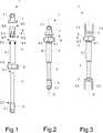
In der
Des Weiteren ist in der
Wie insbesondere in den
In den
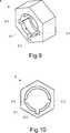
Wie insbesondere in der
In den
In den
Mittels der vorliegenden Erfindung kann in kostengünstiger und einfacher Art und Weise eine Korrigierung einer Lenkradschiefstellung erfolgen, wobei zudem lediglich eine geringe Anzahl zusätzlicher Bauteile in die grundlegend bekannte Lenkung integriert werden müssen, um ein durch vorteilhaft jeden Benutzer mögliches Verstellen des Lenkradwinkels zu realisieren.By means of the present invention can be carried out in a cost effective and simple way, a correction of a steering wheel misalignment, in addition, only a small number of additional components must be integrated into the basically known steering in order to realize a possible by any user adjustable adjustment of the steering wheel angle.
BezugszeichenlisteLIST OF REFERENCE NUMBERS
- 11
- Justierungsvorrichtungadjustment device
- 22
- InnenrohrsegmentInner tube segment
- 2.12.1
- erstes distales Endefirst distal end
- 2.22.2
- zweites distales Endesecond distal end
- 33
- erstes Gelenkelementfirst joint element
- 3.13.1
- Querbohrungcross hole
- 3.23.2
- erster Gelenkelementarmfirst joint element arm
- 3.33.3
- zweiter Gelenkelementarmsecond joint element arm
- 44
- AußenrohrsegmentOuter tube segment
- 4.14.1
- äußere Oberflächeouter surface
- 4.24.2
- innere Oberflächeinner surface
- 4.34.3
- erstes distales Endefirst distal end
- 4.44.4
- zweites distales Endesecond distal end
- 5.1, 5.2,5.1, 5.2,
- Vorsprunghead Start
- 5.3, 5.45.3, 5.4
- Vorsprunghead Start
- 66
- Justierungssegmentadjustment segment
- 6.1, 6.26.1, 6.2
- Führungsnutguide
- 6.3, 6.46.3, 6.4
- Führungsnutguide
- 6.56.5
- erstes distales Endefirst distal end
- 6.66.6
- zweites distales Endesecond distal end
- 6.76.7
- Außengewindeexternal thread
- 6.86.8
- Befestigungselement / BefestigungsabschnittFastener / attachment section
- 77
- zweites Gelenkelementsecond joint element
- 7.17.1
- Querbohrungcross hole
- 7.27.2
- erster Gelenkelementarmfirst joint element arm
- 7.37.3
- zweiter Gelenkelementarmsecond joint element arm
- 88th
- Einstellelementadjustment
- 8.18.1
- Innengewindeinner thread
- 8.2, 8.3, 8.48.2, 8.3, 8.4
- Aussparungrecess
- 9, 9.1, 9.29, 9.1, 9.2
- Führungsnaseguide nose
- 9.3, 9.49.3, 9.4
- Führungsnaseguide nose
- DD
- zentrale Drehachse / Längsachsecentral axis of rotation / longitudinal axis
- αα
- Winkelangle
Claims (10)
Translated fromGermanPriority Applications (1)
| Application Number | Priority Date | Filing Date | Title |
|---|---|---|---|
| DE102015212857.1ADE102015212857B4 (en) | 2014-07-09 | 2015-07-09 | Adjusting device and method for adjusting the center position of a steering wheel of a vehicle |
Applications Claiming Priority (3)
| Application Number | Priority Date | Filing Date | Title |
|---|---|---|---|
| DE102014213300 | 2014-07-09 | ||
| DE102014213300.9 | 2014-07-09 | ||
| DE102015212857.1ADE102015212857B4 (en) | 2014-07-09 | 2015-07-09 | Adjusting device and method for adjusting the center position of a steering wheel of a vehicle |
Publications (2)
| Publication Number | Publication Date |
|---|---|
| DE102015212857A1true DE102015212857A1 (en) | 2016-01-14 |
| DE102015212857B4 DE102015212857B4 (en) | 2016-03-10 |
Family
ID=54867145
Family Applications (1)
| Application Number | Title | Priority Date | Filing Date |
|---|---|---|---|
| DE102015212857.1AActiveDE102015212857B4 (en) | 2014-07-09 | 2015-07-09 | Adjusting device and method for adjusting the center position of a steering wheel of a vehicle |
Country Status (1)
| Country | Link |
|---|---|
| DE (1) | DE102015212857B4 (en) |
Cited By (4)
| Publication number | Priority date | Publication date | Assignee | Title |
|---|---|---|---|---|
| WO2017124073A1 (en)* | 2016-01-15 | 2017-07-20 | Actuant Corporation | Collet locking yoke |
| US10160477B2 (en) | 2016-08-01 | 2018-12-25 | Steering Solutions Ip Holding Corporation | Electric power steering column assembly |
| US10239552B2 (en)* | 2016-10-14 | 2019-03-26 | Steering Solutions Ip Holding Corporation | Rotation control assembly for a steering column |
| DE102023125771A1 (en) | 2023-09-22 | 2025-03-27 | Bayerische Motoren Werke Aktiengesellschaft | Steering assembly and method for setting a predefined orientation of a steering wheel |
Citations (4)
| Publication number | Priority date | Publication date | Assignee | Title |
|---|---|---|---|---|
| DE3400609A1 (en)* | 1983-08-06 | 1985-02-14 | Volkswagenwerk Ag, 3180 Wolfsburg | Arrangement for attaching the hub of a steering wheel on a steering column |
| EP0343035A1 (en)* | 1988-05-19 | 1989-11-23 | Ecia - Equipements Et Composants Pour L'industrie Automobile | Angular position-adjusting device for a steering wheel on the steering column of an automotive vehicle |
| DE4000994A1 (en)* | 1989-01-28 | 1990-08-02 | Volkswagen Ag | Automotive steering gear with universal joint - has transverse adjusting bolt in outer steering column tube, engaging teeth in inner tube |
| DE102004028829A1 (en)* | 2004-06-15 | 2005-12-29 | Zf Lenksysteme Gmbh | Method for operating a steering system |
- 2015
- 2015-07-09DEDE102015212857.1Apatent/DE102015212857B4/enactiveActive
Patent Citations (4)
| Publication number | Priority date | Publication date | Assignee | Title |
|---|---|---|---|---|
| DE3400609A1 (en)* | 1983-08-06 | 1985-02-14 | Volkswagenwerk Ag, 3180 Wolfsburg | Arrangement for attaching the hub of a steering wheel on a steering column |
| EP0343035A1 (en)* | 1988-05-19 | 1989-11-23 | Ecia - Equipements Et Composants Pour L'industrie Automobile | Angular position-adjusting device for a steering wheel on the steering column of an automotive vehicle |
| DE4000994A1 (en)* | 1989-01-28 | 1990-08-02 | Volkswagen Ag | Automotive steering gear with universal joint - has transverse adjusting bolt in outer steering column tube, engaging teeth in inner tube |
| DE102004028829A1 (en)* | 2004-06-15 | 2005-12-29 | Zf Lenksysteme Gmbh | Method for operating a steering system |
Cited By (7)
| Publication number | Priority date | Publication date | Assignee | Title |
|---|---|---|---|---|
| WO2017124073A1 (en)* | 2016-01-15 | 2017-07-20 | Actuant Corporation | Collet locking yoke |
| US10487881B2 (en) | 2016-01-15 | 2019-11-26 | Weasler Engineering, Inc. | Collet locking yoke |
| US10160477B2 (en) | 2016-08-01 | 2018-12-25 | Steering Solutions Ip Holding Corporation | Electric power steering column assembly |
| US10239552B2 (en)* | 2016-10-14 | 2019-03-26 | Steering Solutions Ip Holding Corporation | Rotation control assembly for a steering column |
| US20190092375A1 (en)* | 2016-10-14 | 2019-03-28 | Steering Solutions Ip Holding Corporation | Rotation control assembly for a steering column |
| US10676126B2 (en)* | 2016-10-14 | 2020-06-09 | Steering Solutions Ip Holding Corporation | Rotation control assembly for a steering column |
| DE102023125771A1 (en) | 2023-09-22 | 2025-03-27 | Bayerische Motoren Werke Aktiengesellschaft | Steering assembly and method for setting a predefined orientation of a steering wheel |
Also Published As
| Publication number | Publication date |
|---|---|
| DE102015212857B4 (en) | 2016-03-10 |
Similar Documents
| Publication | Publication Date | Title |
|---|---|---|
| DE102014103028B3 (en) | Steering column for a motor vehicle | |
| EP3122613B1 (en) | Steering device | |
| EP3500476A1 (en) | Control yoke for steering a motor vehicle | |
| EP3428041B1 (en) | Multifunctional steering column, motor vehicle and method for operating a motor vehicle | |
| EP3148860B1 (en) | Steering shaft for a motor vehicle steering system | |
| DE102013217753B3 (en) | Coupling element, coupling arrangement and method for producing a coupling element | |
| DE102015212857B4 (en) | Adjusting device and method for adjusting the center position of a steering wheel of a vehicle | |
| DE102016216011B4 (en) | Articulated shaft system, steering system and motor vehicle | |
| DE112020005479T5 (en) | ELECTRIC (STEER-BY-WIRE) STEERING DEVICE | |
| WO2013124043A1 (en) | Steering column for a motor vehicle | |
| EP2209959B1 (en) | Compression closure | |
| DE112020002349T5 (en) | VEHICLE STEERING DEVICE | |
| EP3649038B1 (en) | Adjusting device for a chassis of a motor vehicle and rear-axle steering system | |
| DE102019217965A1 (en) | Steering gear for a steer-by-wire steering device of a motor vehicle | |
| DE102019212438A1 (en) | Steering column for a motor vehicle | |
| EP2349815A1 (en) | Steering gear | |
| DE102024201871A1 (en) | STEERING ARRANGEMENT FOR A VEHICLE | |
| EP3665066A1 (en) | Wheel suspension | |
| DE4208497C1 (en) | Coaxial connector for car steering linkages - has sleeve with inner edge toothing, pushed onto rack rod end surface | |
| DE19755677A1 (en) | Wheel toe-in adjustment assembly for road vehicles | |
| DE102020201514A1 (en) | Steering gear for a motor vehicle and method for assembling a steering gear | |
| DE102008050012B4 (en) | ball joint | |
| EP0300338A2 (en) | Device for attaching a steering wheel hub to a steering column | |
| DE3704234C2 (en) | Device for aligning an input shaft of a steering gear | |
| EP2386433A1 (en) | Axle assembly |
Legal Events
| Date | Code | Title | Description |
|---|---|---|---|
| R012 | Request for examination validly filed | ||
| R016 | Response to examination communication | ||
| R018 | Grant decision by examination section/examining division | ||
| R020 | Patent grant now final |