DE102015208084A1 - Method for generating a contrast image of an object condition and related devices - Google Patents
Method for generating a contrast image of an object condition and related devicesDownload PDFInfo
- Publication number
- DE102015208084A1 DE102015208084A1DE102015208084.6ADE102015208084ADE102015208084A1DE 102015208084 A1DE102015208084 A1DE 102015208084A1DE 102015208084 ADE102015208084 ADE 102015208084ADE 102015208084 A1DE102015208084 A1DE 102015208084A1
- Authority
- DE
- Germany
- Prior art keywords
- image
- axis
- contrast
- color
- illumination
- Prior art date
- Legal status (The legal status is an assumption and is not a legal conclusion. Google has not performed a legal analysis and makes no representation as to the accuracy of the status listed.)
- Pending
Links
Images


Classifications
- G—PHYSICS
- G02—OPTICS
- G02B—OPTICAL ELEMENTS, SYSTEMS OR APPARATUS
- G02B21/00—Microscopes
- G02B21/36—Microscopes arranged for photographic purposes or projection purposes or digital imaging or video purposes including associated control and data processing arrangements
- G02B21/365—Control or image processing arrangements for digital or video microscopes
- G02B21/367—Control or image processing arrangements for digital or video microscopes providing an output produced by processing a plurality of individual source images, e.g. image tiling, montage, composite images, depth sectioning, image comparison
- G—PHYSICS
- G06—COMPUTING OR CALCULATING; COUNTING
- G06T—IMAGE DATA PROCESSING OR GENERATION, IN GENERAL
- G06T5/00—Image enhancement or restoration
- G06T5/50—Image enhancement or restoration using two or more images, e.g. averaging or subtraction
- G—PHYSICS
- G02—OPTICS
- G02B—OPTICAL ELEMENTS, SYSTEMS OR APPARATUS
- G02B21/00—Microscopes
- G02B21/0004—Microscopes specially adapted for specific applications
- G02B21/002—Scanning microscopes
- G02B21/0024—Confocal scanning microscopes (CSOMs) or confocal "macroscopes"; Accessories which are not restricted to use with CSOMs, e.g. sample holders
- G02B21/0052—Optical details of the image generation
- G02B21/0056—Optical details of the image generation based on optical coherence, e.g. phase-contrast arrangements, interference arrangements
- G—PHYSICS
- G06—COMPUTING OR CALCULATING; COUNTING
- G06T—IMAGE DATA PROCESSING OR GENERATION, IN GENERAL
- G06T7/00—Image analysis
- G06T7/90—Determination of colour characteristics
- H—ELECTRICITY
- H04—ELECTRIC COMMUNICATION TECHNIQUE
- H04N—PICTORIAL COMMUNICATION, e.g. TELEVISION
- H04N23/00—Cameras or camera modules comprising electronic image sensors; Control thereof
- H04N23/60—Control of cameras or camera modules
- H—ELECTRICITY
- H04—ELECTRIC COMMUNICATION TECHNIQUE
- H04N—PICTORIAL COMMUNICATION, e.g. TELEVISION
- H04N5/00—Details of television systems
- H04N5/222—Studio circuitry; Studio devices; Studio equipment
- H04N5/262—Studio circuits, e.g. for mixing, switching-over, change of character of image, other special effects ; Cameras specially adapted for the electronic generation of special effects
- H04N5/265—Mixing
- H—ELECTRICITY
- H04—ELECTRIC COMMUNICATION TECHNIQUE
- H04N—PICTORIAL COMMUNICATION, e.g. TELEVISION
- H04N9/00—Details of colour television systems
- H04N9/79—Processing of colour television signals in connection with recording
- G—PHYSICS
- G06—COMPUTING OR CALCULATING; COUNTING
- G06T—IMAGE DATA PROCESSING OR GENERATION, IN GENERAL
- G06T2207/00—Indexing scheme for image analysis or image enhancement
- G06T2207/10—Image acquisition modality
- G06T2207/10056—Microscopic image
- G—PHYSICS
- G06—COMPUTING OR CALCULATING; COUNTING
- G06T—IMAGE DATA PROCESSING OR GENERATION, IN GENERAL
- G06T2207/00—Indexing scheme for image analysis or image enhancement
- G06T2207/10—Image acquisition modality
- G06T2207/10056—Microscopic image
- G06T2207/10061—Microscopic image from scanning electron microscope
- G—PHYSICS
- G06—COMPUTING OR CALCULATING; COUNTING
- G06T—IMAGE DATA PROCESSING OR GENERATION, IN GENERAL
- G06T2207/00—Indexing scheme for image analysis or image enhancement
- G06T2207/10—Image acquisition modality
- G06T2207/10141—Special mode during image acquisition
- G06T2207/10152—Varying illumination
- G—PHYSICS
- G06—COMPUTING OR CALCULATING; COUNTING
- G06T—IMAGE DATA PROCESSING OR GENERATION, IN GENERAL
- G06T2207/00—Indexing scheme for image analysis or image enhancement
- G06T2207/20—Special algorithmic details
- G06T2207/20212—Image combination
- G06T2207/20221—Image fusion; Image merging
Landscapes
- Engineering & Computer Science (AREA)
- Physics & Mathematics (AREA)
- Multimedia (AREA)
- General Physics & Mathematics (AREA)
- Signal Processing (AREA)
- Theoretical Computer Science (AREA)
- Computer Vision & Pattern Recognition (AREA)
- Chemical & Material Sciences (AREA)
- Analytical Chemistry (AREA)
- Optics & Photonics (AREA)
- Image Processing (AREA)
- Microscoopes, Condenser (AREA)
Abstract
Translated fromGermanDescription
Translated fromGermanDie vorliegende Erfindung betrifft ein Verfahren zum Generieren eines Kontrastbildes, insbesondere zum Ablesen von Höhenverlaufs- und/oder Phasenverlaufsinformationen einer Objektbeschaffenheit und diesbezügliche Vorrichtungen.The present invention relates to a method for generating a contrast image, in particular for reading altitude profile and / or phase history information of an object condition and related devices.
Sowohl in der klassischen biologischen Mikroskopie als auch in der Materialmikroskopie werden neben der normalen Hellfeld-Bildgebung verschiedene Formen von Kontrastverfahren verwendet, um zusätzliche Informationen über das beobachtete Objekt zu gewinnen. Beispiele hierfür sind Phasenkontrastverfahren (beispielsweise Zernike, Differentialinterferenzkontrast – DIC) oder auch alternative Bildgenerierungsverfahren (beispielsweise Dunkelfeld). Aktuell werden Varianten beschrieben, wie Kontrastbilder aus Einzelbildern berechnet werden können. In den bisherigen Veröffentlichungen werden dabei DIC-Alternativen beschrieben, wobei dies in der Regel zu grauen Bildern führt und wobei die Qualität der berechneten Kontrastbilder stark richtungsabhängig ist. Im Allgemeinen haben alle beschriebenen Kontraste den Nachteil, dass sie eine spezielle Eigenschaft des Objekts hervorheben, dafür jedoch andere Eigenschaften ignorieren beziehungsweise abschwächen. Beispielsweise haben DIC-Verfahren beziehungsweise das digitale Analogon der Bildung der Differenz von Bildern gegenüberliegender Beleuchtungsrichtungen (DPC) den Nachteil, dass sie lediglich richtungsabhängige Grauwertbilder generieren.In classical biological microscopy as well as in material microscopy, in addition to normal bright-field imaging, various forms of contrasting techniques are used to obtain additional information about the observed object. Examples include phase contrast methods (for example Zernike, differential interference contrast - DIC) or alternative image generation methods (for example, dark field). Currently variants are described how contrast images can be calculated from single images. In the previous publications DIC alternatives are described, which usually leads to gray images and the quality of the calculated contrast images is strongly direction-dependent. In general, all the contrasts described have the disadvantage of highlighting a particular property of the object, but ignoring or mitigating other properties. For example, DIC methods or the digital analogue of forming the difference of images of opposing illumination directions (DPC) have the disadvantage that they only generate direction-dependent gray value images.
Daher wäre es wünschenswert, eine Möglichkeit bereitzustellen, welche ein richtungsabhängiges Farbcodieren einer Objektbeschaffenheit eines Objektes erlaubt, insbesondere von Höhenverlaufs- und/oder Phasenverlaufsinformationen der Objektbeschaffenheit.Therefore, it would be desirable to provide an option that allows directional color coding of an object's texture of an object, particularly elevation and / or phase history information of the object's texture.
Es ist Ziel der Erfindung, eine Möglichkeit vorzuschlagen, welche zumindest einen Teil der im Stand der Technik bekannten Nachteile vermeidet oder zumindest vermindert.It is an object of the invention to propose a possibility which avoids or at least reduces at least some of the disadvantages known in the prior art.
Die Aufgabe wird erfindungsgemäß gelöst, mittels eines Verfahrens gemäß dem Hauptanspruch, sowie mittels Vorrichtungen gemäß der nebengeordneten Ansprüche.The object is achieved by a method according to the main claim, and by means of devices according to the independent claims.
Der Gegenstand des Hauptanspruches betrifft dabei ein Kontrastbildungsverfahren zum Generieren eines Kontrastbildes, vorzugsweise aus mikroskopischen Abbildungen, insbesondere zum Ablesen von Höhen- und/oder Phasenverlaufsinformationen einer Objektbeschaffenheit. Dabei weist das Kontrastbildungsverfahren auf: Illuminieren eines Objektes mittels einer Illuminationssequenz basierend auf einer oder einer Vielzahl (zwei oder mehr) an Illuminationsquellen. Erstellen eines Illuminationsbildes des Objektes für eine jede Illumination der Illuminationssequenz. Überlagern jeweils zweier bezüglich einer ersten Achse benachbarter Illuminationsbilder zu einem ersten Gesamtachsenbild der ersten Achse. Überlagern jeweils zweier bezüglich einer zweiten Achse benachbarter Illuminationsbilder zu einem zweiten Gesamtachsenbild der zweiten Achse. Erstellen eines ersten Farbverlaufsbildes basierend auf dem ersten Gesamtachsenbild. Erstellen eines zweiten Farbverlaufsbildes basierend auf dem zweiten Gesamtachsenbild. Transformieren des ersten Farbverlaufsbildes und des zweiten Farbverlaufsbildes in einen Farbraum. Und generieren eines Kontrastbildes, basierend auf dem transformierten ersten Farbverlaufsbild und dem zweiten Farbverlaufsbild in den Farbraum, derart, dass vier Richtungsinformationen eines Phasen+ oder Höhenverlaufes einer Beschaffenheit des Objektes farbcodiert darstellbar sind.The subject matter of the main claim relates to a contrast formation method for generating a contrast image, preferably from microscopic images, in particular for reading height and / or phase history information of an object condition. Here, the contrast forming method comprises: illuminating an object by means of an illumination sequence based on one or a plurality (two or more) of illumination sources. Creating an illumination image of the object for each illumination of the illumination sequence. Overlay two each with respect to a first axis adjacent Illuminationsbilder to a first overall axis image of the first axis. Overlay two each with respect to a second axis adjacent Illuminationsbilder to a second overall axis image of the second axis. Create a first gradient image based on the first overall axis image. Create a second color gradient image based on the second overall axis image. Transforming the first color gradient image and the second color gradient image into a color space. And generate a contrast image, based on the transformed first color gradient image and the second color gradient image in the color space, such that four direction information of a phase + or height profile of a condition of the object are color-coded represented.
Die Verfahrensschritte können dabei automatisiert ausgeführt werden. Eine Höhenverlaufsinformationen einer Objektbeschaffenheit im Sinne der Erfindung kann dabei eine Information aufweisen, welche Hinweise über eine Objektbeschaffenheit in allen drei Raumdimensionen gibt. Eine Illuminationssequenz im Sinne der Erfindung kann dabei eine konkrete Folge von Illuminationen sein. Dazu kann jeweils eine Illuminationsquelle aktiviert werden, wobei die restlichen Illuminationsquellen inaktiv sind. Eine Illuminationsquelle im Sinne der Erfindung kann dabei eine Lichtquelle sein, um das Objekt zu beleuchten. Durch die Anordnung mehrerer solcher Illuminationsquellen um das Objekt, kann somit eine winkelselektive Beleuchtung des Objektes erreicht werden. Beispielsweise kann die Illuminationsquelle eine an einem Objektiv angeordnete Ringlichtbeleuchtung oder Einzel-LED-Beleuchtung mit mehreren Einzellichtquellen (z.B. LED’s) sein, mit denen eine Beleuchtung des Objektes aus den verschiedenen Quadranten (Nord-NO-Ost-SO-Süd-SW-West-NW) in vorgegebener Reihenfolge einzeln oder kombiniert realisiert werden kann. Ein Illuminationsbild im Sinne der Erfindung kann dabei eine Aufnahme eines Objektes innerhalb der Illuminationssequenz sein. Ein Überlagern zweier benachbarter Illuminationsbilder im Sinne der Erfindung kann dabei ein Vorgang sein, bei welchem jeweils gleiche Bildanteile zweier Bilder verstärkt oder abgeschwächt werden. Die kann beispielsweise pixelweise erfolgen. Ein Gesamtachsenbild im Sinne der Erfindung kann dabei ein Bild sein, welches durch Überlagern beziehungsweise Kombinieren von Illuminationsbildern entsteht. Dabei können diejenigen Illuminationsbilder herangezogen werden, welche jeweils bezüglich der gleichen Achse benachbart sind.The process steps can be carried out automatically. A height course information of an object condition within the meaning of the invention can have information which gives indications of an object condition in all three space dimensions. An illumination sequence within the meaning of the invention can be a concrete sequence of illuminations. For this purpose, one illumination source each can be activated, with the remaining sources of illumination being inactive. An illumination source in the sense of the invention can be a light source in order to illuminate the object. By arranging a plurality of such illumination sources around the object, an angle-selective illumination of the object can thus be achieved. For example, the illumination source may be a ring light illumination arranged on a lens or individual LED illumination with a plurality of individual light sources (eg LEDs) with which illumination of the object from the various quadrants (north-north-east-east-south-south-west-west) NW) can be realized in a predetermined order individually or in combination. An illumination image within the meaning of the invention can be a photograph of an object within the illumination sequence. Overlaying two adjacent illumination images in the sense of the invention can be a process in which in each case the same image components of two images are amplified or attenuated. This can be done, for example, pixel by pixel. An overall axis image in the sense of the invention can be an image which is produced by superimposing or combining illumination images. In this case, those Illuminationsbilder can be used, which are adjacent to each other with respect to the same axis.
Ein Farbverlaufsbild im Sinne der Erfindung kann dabei ein Bild sein, welches entsteht, wenn über ein Gesamtachsenbild ein entsprechender Farbverlauf gelegt wird. Beispielsweise kann in einem kartesischen Koordinatensystem für die x-Achse ein erster Farbverlauf, wie beispielsweise ein blau-gelb Verlauf gelegt werden, und für die y-Achse ein weiterer Farbverlauf, beispielsweise ein rot-grün Verlauf gelegt werden. Das Farbverlaufsbild des x-Achsen Gesamtachsenbildes würde dann einen blau-gelb Farbverlauf aufweisen. Dieser Farbverlauf kann dann indikativ sein, für einen Höhenverlauf des Objektes in der horizontalen Achse, während dann der Farbverlauf des Farbverlaufsbildes des y-Achsen Gesamtachsenbildes indikativ sein kann, für einen Höhenverlauf des Objektes in der vertikalen Achse. Insbesondere kann ein Farbverlauf auch ein Kontrast sein. Ist der Farbverlauf ein Kontrast, so kann der Höhenverlauf der Beschaffenheit des Objektes farbcodiert darstellbar werden, indem eine Helligkeitsinformation als Farbcodierung verwendet wird, wobei die Helligkeit im Bild beziehungsweise die Helligkeit des Pixels die Höheninformation darstellt. Ein Farbraum im Sinne der Erfindung kann dabei ein digital festgelegter Farbraum sein, wie er beispielsweise für Computerbildschirme und/oder im Print-Bereich eingesetzt wird. Durch die erfindungsgemäße Lehre wird der Vorteil erreicht, dass sowohl eine Information über die Materialbeschaffenheit als auch eine Höheninformation des Objektes in einem Bild dargestellt werden können. Ferner kann das Objekt in Originalfarben dargestellt werden und über die Helligkeit kann eine räumliche Zuordnung erreicht werden. Somit kann auf einfache und schnelle Weise eine Kombination von Einzelkontrasten in einem Einzelbild erreicht werden, um mehr Informationen über das Objekt in dem Objektbild darzustellen.A color gradient image in the sense of the invention can be an image which arises when a corresponding one is available over an overall axis image Gradient is laid. For example, in a Cartesian coordinate system for the x-axis, a first color gradient, such as a blue-yellow gradient are laid, and for the y-axis another color gradient, such as a red-green gradient are laid. The color gradient image of the x-axis overall axis image would then have a blue-yellow color gradient. This color gradient may then be indicative of a height gradient of the object in the horizontal axis, while then the color gradient of the color gradient image of the y-axis overall axis image may be indicative of a height gradient of the object in the vertical axis. In particular, a color gradient can also be a contrast. If the color gradient is a contrast, then the height profile of the nature of the object can be represented in color-coded manner by using brightness information as color coding, the brightness in the image or the brightness of the pixel representing the height information. A color space within the meaning of the invention can be a digitally defined color space, as used for example for computer screens and / or in the print area. The teaching according to the invention achieves the advantage that both information about the material properties and height information of the object can be displayed in an image. Furthermore, the object can be displayed in original colors and a spatial assignment can be achieved via the brightness. Thus, a combination of individual contrasts in a single image can be achieved in a simple and fast manner in order to display more information about the object in the object image.
Der Gegenstand eines nebengeordneten Anspruches betrifft dabei eine kontrastbildende Vorrichtung zur Generierung eines Kontrastbildes, vorzugsweise aus mikroskopischen Abbildungen, insbesondere zum Ablesen von Höhenverlaufsinformationen einer Objektbeschaffenheit, besonders bevorzugt zum Lichtmikroskopieren, die Kontrastbildungsvorrichtung aufweisend eine Bildaufnahmevorrichtung und eine Kontrastbildungsvorrichtung. Dabei ist die Bildaufnahmevorrichtung dazu eingerichtet, ein Bild eines Objekt aufzunehmen bzw. in bekannter Weise digital zu erfassen und ein Ergebnis der Bildaufnahme, also ein Bild an die Kontrastbildungsvorrichtung zu übermitteln. Dabei ist die Kontrastbildungsvorrichtung dazu eingerichtet, ein erfindungsgemäßes Kontrastbildungsverfahren auszuführen. Eine Bildaufnahmevorrichtung im Sinne der Erfindung kann dabei eine Vorrichtung sein, welche geeignet ist, ein Objekt optisch zu erfassen und darzustellen. Insbesondere kann die Bildaufnahmevorrichtung ein Mikroskop sein, besonders bevorzugt ein Lichtmikroskop. Ferner kann die Bildaufnahmevorrichtung eine Mehrzahl an Illuminationsquellen zur winkelselektiven Beleuchtung des abzubildenden Objektes aufweisen. Ein Kontrastbildungsvorrichtung im Sinne der Erfindung kann dabei eine Vorrichtung aufweisen, welche dazu eingerichtet ist, Kontraste aus Bildern, welche durch die Beleuchtung des Objektes bei der Bildaufnahme entstehen, zu erzeugen. Die Kontrastbildungsvorrichtung kann hierzu eine CPU und eine zugehörige Architektur aufweisen. Insbesondere kann die Kontrastbildungsvorrichtung in eine Bildverarbeitungseinheit des Mikroskops integriert oder ein entsprechend eingerichteter Computer sein.The subject of a non-independent claim relates to a contrast-generating device for generating a contrast image, preferably from microscopic images, in particular for reading height characteristic information of an object condition, particularly preferably for light microscopy, the contrast-forming device comprising an image-recording device and a contrast-forming device. In this case, the image recording device is set up to take an image of an object or to digitally record it in a known manner and to transmit a result of the image recording, that is an image, to the contrast-forming device. In this case, the contrast-forming device is set up to carry out a contrast-forming method according to the invention. An image recording device according to the invention can be a device which is suitable for optically detecting and displaying an object. In particular, the image recording device may be a microscope, particularly preferably a light microscope. Furthermore, the image recording device can have a plurality of illumination sources for the angle-selective illumination of the object to be imaged. A contrast-forming device in the sense of the invention can have a device which is set up to generate contrasts from images which are produced by the illumination of the object during image recording. The contrast-building device may for this purpose have a CPU and an associated architecture. In particular, the contrast-forming device can be integrated in an image processing unit of the microscope or can be a computer set up accordingly.
Durch die erfindungsgemäße Lehre wird der Vorteil erreicht, dass kostengünstig eine Vorrichtung bereitgestellt werden kann, welche es ermöglicht, ein Objekt winkelselektiv zu beleuchten, dabei eine Mehrzahl von Bildern zu erfassen, um und eine Kombination von Einzelkontrasten der erfassten Bilder in einem Einzelbild zu erreichen, um mehr Informationen über das Objekt in dem Objektbild darzustellen.The teaching according to the invention affords the advantage that a device can be provided at low cost which makes it possible to illuminate an object in an angle-selective manner, thereby acquiring a plurality of images in order to achieve a combination of individual contrasts of the captured images in a single image, to show more information about the object in the object image.
Der Gegenstand eines weiteren nebengeordneten Anspruches betrifft dabei ein Computerprogrammprodukt für eine erfindungsgemäße kontrastbildende Vorrichtung, welche nach einem erfindungsgemäßen Kontrastbildungsverfahren betreibbar ist. Das Computerprogramm umfasst Programmcodemittel, in denen die Schritte des erfindungsgemäßen Kontrastbildungsverfahrens mittels einer Bildverarbeitung implementiert sind. Das Computerprogramm kann in einer Echtzeit-Bildverarbeitungseinheit als Hardwarecode implementiert sein, oder alternativ als reine Bildnachverarbeitung ausgeführt sein.The subject matter of a further independent claim relates to a computer program product for a contrast-producing device according to the invention, which can be operated according to a contrast-forming method according to the invention. The computer program comprises program code means in which the steps of the contrast formation method according to the invention are implemented by means of image processing. The computer program may be implemented in a real-time image processing unit as a hardware code, or alternatively as pure image post-processing.
Bei der vorteilhaften Integration des Programmcodes für das Kontrastbildungsverfahren in die Hardware (Digitale Bildverarbeitungseinheit eines Lichtmikroskopes) kann eine sehr schnelle Bildverarbeitung erfolgen und das Ergebnis quasi als „Live“-Bild betrachtet werden, da die Aufnahme der Einzelbilder und deren Bildverarbeitung schneller erfolgt als die Wiedergabefrequenz des Live-Bildes.In the case of the advantageous integration of the program code for the contrasting method into the hardware (digital image processing unit of a light microscope), very fast image processing can take place and the result can be regarded as a "live" image, since the acquisition of the individual images and their image processing takes place faster than the reproduction frequency the live picture.
Durch die erfindungsgemäße Lehre wird der Vorteil erreicht, dass damit das Kontrastbildungsverfahren automatisiert betreibbar ist und auf einfache und kostengünstige Weise, für entsprechende, verschiedene erfindungsgemäße Vorrichtungen bereitgestellt werden kann. Besonders vorteilhaft ist das Computerprogrammprodukt in die Bildverarbeitungseinheit des Mikroskopes integriert bzw. integrierbar. Es kann auch als Hardwarecode in die Bildverarbeitungshardware integriert sein.The teaching according to the invention affords the advantage that the contrast-forming method can thus be operated in an automated manner and can be provided in a simple and cost-effective manner for corresponding, different devices according to the invention. Particularly advantageous is the computer program product integrated into the image processing unit of the microscope or integrated. It can also be integrated as hardware code in the image processing hardware.
Der Gegenstand eines weiteren nebengeordneten Anspruches betrifft dabei einen Datenträger aufweisend ein erfindungsgemäßes Computerprogrammprodukt.The subject matter of a further independent claim relates to a data carrier comprising a computer program product according to the invention.
Durch die erfindungsgemäße Lehre wird der Vorteil erreicht, dass damit das Kontrastbildungsverfahren automatisiert betreibbar ist und auf einfache und kostengünstige Weise, für entsprechende, verschiedene erfindungsgemäße Vorrichtungen bereitgestellt werden kann und dabei einfach transportiert werden kann, um das Verfahren direkt auf die entsprechende erfindungsgemäße Vorrichtung, am Ort der Vorrichtung portieren zu können.Due to the teaching of the invention, the advantage is achieved that so that the Contrast-forming method is automated and can be provided in a simple and cost-effective manner, for corresponding, various devices of the invention and can be easily transported to port the method directly to the corresponding device according to the invention, at the location of the device.
Bevor nachfolgend Ausgestaltungen der Erfindung eingehender beschrieben werden, ist zunächst festzuhalten, dass die Erfindung nicht auf die beschriebenen Komponenten oder die beschriebenen Verfahrensschritte beschränkt ist. Weiterhin stellt auch die verwendete Terminologie keine Einschränkung dar, sondern hat lediglich beispielhaften Charakter. Soweit in der Beschreibung und den Ansprüchen der Singular verwendet wird ist dabei jeweils der Plural mitumfasst, soweit der Kontext dies nicht explizit ausschließt. Etwaige Verfahrensschritte können, soweit der Kontext dies nicht explizit ausschließt, automatisiert ausgeführt werden.Before describing embodiments of the invention in more detail below, it should first be noted that the invention is not limited to the described components or the described method steps. Furthermore, the terminology used is not a limitation, but has only exemplary character. Insofar as the singular is used in the description and the claims, the plural is also included, unless the context explicitly excludes this. Any method steps can, if the context does not explicitly exclude this, be carried out automatically.
Nachfolgend werden weitere exemplarische Ausgestaltungen des erfindungsgemäßen Verfahrens erläutert.Hereinafter, further exemplary embodiments of the method according to the invention will be explained.
Entsprechend einer ersten exemplarischen Ausgestaltung weist in dem Kontrastbildungsverfahren das Überlagern jeweils zweier bezüglich der ersten Achse benachbarter Illuminationsbilder zu dem ersten Gesamtachsenbild der ersten Achse, und das Überlagern jeweils zweier bezüglich der zweiten Achse benachbarter Illuminationsbilder zu dem zweiten Gesamtachsenbild der zweiten Achse, jeweils entsprechend auf: Verrechnen jeweils zweier bezüglich der entsprechenden ersten Achse beziehungsweise zweiten Achse benachbarter Illuminationsbilder zu entsprechenden Zwischenbildern bezüglich der entsprechenden ersten Achse beziehungsweise zweiten Achse. Verrechnen der entsprechenden Zwischenbilder zu dem entsprechenden ersten Gesamtachsenbild beziehungsweise dem zweiten Gesamtachsenbild. Dabei weist das jeweilige Verrechnen jeweils eine Addition oder eine Subtraktion auf. Dabei kann aber auch zusätzlich eine Skalierung, Bildfilterung oder eine andersartige Bildbearbeitung an den Einzelbildern ausgeführt werden – vor und/oder nach der Addition bzw. Subtraktion. Diese Ausgestaltung weist den Vorteil auf, dass damit ein Verfahrensteil wiederholt angewendet werden kann, um das entsprechende Gesamtachsenbild zu erhalten. Dadurch kann das Verfahren vereinfacht werden.According to a first exemplary embodiment, in the contrasting method, each superimposing two illumination images adjacent to the first axis to the first overall axis image of the first axis, and superimposing each two adjacent to the second axis illumination images to the second overall axis image of the second axis, respectively corresponding to: Compute two each with respect to the corresponding first axis or second axis of adjacent illumination images to corresponding intermediate images with respect to the corresponding first axis or second axis. Compute the corresponding intermediate images to the corresponding first overall axis image or the second overall axis image. In each case, the respective calculation has an addition or a subtraction. In addition, however, a scaling, image filtering or a different type of image processing on the individual images can also be performed - before and / or after the addition or subtraction. This refinement has the advantage that a method part can be used repeatedly in order to obtain the corresponding overall axis image. This can simplify the process.
Entsprechend einer weiteren exemplarischen Ausgestaltung weist das Kontrastbildungsverfahren ferner auf, dass das Überlagern der entsprechenden Illuminationsbilder zu dem ersten Gesamtachsenbild der ersten Achse beziehungsweise zu dem zweiten Gesamtachsenbild der zweiten Achse, jeweils eine entsprechende Graubildtransformation aufweist. Diese Ausgestaltung weist den Vorteil auf, dass damit das Gesamtachsenbild transformiert werden kann, derart, dass nicht benötigte Farbinformationen weggelassen werden, um das Gesamtachsenbild auf einfache Weise für andere Informationen verwenden zu können.According to a further exemplary embodiment, the contrasting method further comprises superimposing a corresponding gray image transformation on the first overall axis image of the first axis or on the second overall axis image of the second axis, respectively, overlaying the corresponding illumination images. This refinement has the advantage that the overall axis image can thus be transformed in such a way that unnecessary color information is omitted in order to be able to easily use the overall axis image for other information.
Entsprechend einer weiteren exemplarischen Ausgestaltung weist in dem Kontrastbildungsverfahren das Transformieren des ersten Farbverlaufsbildes und des zweiten Farbverlaufsbildes in den Farbraum auf: Zuweisen des ersten Farbverlaufsbildes zu einem ersten bildgebenden Kanal des Farbraumes. Und zuweisen des zweiten Farbverlaufsbildes zu einem zweiten bildgebenden Kanal des Farbraumes. Ein bildgebender Kanal des Farbraumes im Sinne der Erfindung kann dabei ein Kanal des Farbraumes sein, welcher zur visuellen Darstellung genutzt wird. Der RGB-Farbraum beispielsweise weist drei bildgebende Kanäle auf, den R-Kanal, den G-Kanal und den B-Kanal, auf welchem unterschiedliche Farben kodiert sind. Diese Ausgestaltung weist den Vorteil auf, dass die bildgebenden Kanäle des Farbraumes selbst zur Informationsführung über die Objektbeschaffenheit genutzt werden können.According to a further exemplary embodiment, in the contrast formation method, transforming the first color gradient image and the second color gradient image into the color space comprises: assigning the first color gradient image to a first imaging channel of the color space. And assign the second color gradient image to a second imaging channel of the color space. An imaging channel of the color space in the sense of the invention can be a channel of the color space, which is used for visual representation. The RGB color space, for example, has three imaging channels, the R channel, the G channel and the B channel, on which different colors are coded. This refinement has the advantage that the imaging channels of the color space can themselves be used to guide the information about the nature of the object.
Entsprechend einer weiteren exemplarischen Ausgestaltung weist in dem Kontrastbildungsverfahren das Transformieren des ersten Farbverlaufsbildes und des zweiten Farbverlaufsbildes in den Farbraum ein Zuweisen einer Helligkeitsinformation zu einem dritten bildgebenden Kanal des Farbraumes auf. Diese Ausgestaltung weist den Vorteil auf, dass mittels der Helligkeitsinformation das Bild normiert werden kann oder auch dazu benutzt werden kann, eine weitere Information über die Objektbeschaffenheit im Farbraum darzustellen.According to a further exemplary embodiment, in the contrast formation method, transforming the first color gradient image and the second color gradient image into the color space comprises assigning brightness information to a third image channel of the color space. This refinement has the advantage that the image can be normalized by means of the brightness information or can also be used to represent further information about the nature of the object in the color space.
Entsprechend einer weiteren exemplarischen Ausgestaltung weist in dem Kontrastbildungsverfahren das Transformieren des ersten Farbverlaufsbildes und des zweiten Farbverlaufsbildes in den Farbraum ein Zuweisen eines Grauwertbildes zu einem dritten bildgebenden Kanal des Farbraumes auf. Ein Grauwertbild im Sinne der Erfindung kann dabei eine Schwarz-weiß Verlaufsinformation des Bildes sein. Das Grauwertbild kann auch einen Kontrast aufweisen. Diese Ausgestaltung weist den Vorteil auf, dass mittels des Grauwertbildes das Bild normiert werden kann oder auch dazu benutzt werden kann, eine weitere Information über die Objektbeschaffenheit im Farbraum darzustellen.According to a further exemplary embodiment, in the contrast formation method, transforming the first color gradient image and the second color gradient image into the color space comprises assigning a gray value image to a third image-forming channel of the color space. A gray scale image in the sense of the invention can be a black and white history information of the image. The gray value image can also have a contrast. This refinement has the advantage that the image can be normalized by means of the gray scale image or can also be used to represent further information about the object texture in the color space.
Entsprechend einer weiteren exemplarischen Ausgestaltung weist das Kontrastbildungsverfahren ferner auf, dass zwei Richtungsinformationen der vier Richtungsinformationen indikativ für jeweils eine Richtung entlang der ersten Achse sind. Und ferner weist das Kontrastbildungsverfahren auf, dass zwei weitere Richtungsinformationen der vier Richtungsinformationen indikativ für jeweils eine Richtung entlang der zweiten Achse sind. Diese Ausgestaltung weist den Vorteil auf, dass eine Höhenverlaufsinformationen der Objektbeschaffenheit auf einfache Weist im Farbraum darstellbar wird, indem die Richtungen der Achsen, welche für die Generierung des Gesamtachsenbildes genutzt werden, auch für die Höhenverlaufsinformationen genutzt werden.According to a further exemplary embodiment, the contrasting method further comprises that two directional information of the four Direction information is indicative of one direction along the first axis. And further, the contrast forming method has two further direction information of the four direction information indicative of one direction along the second axis. This refinement has the advantage that a height profile information of the object structure can be displayed in a simple manner in the color space by also using the directions of the axes which are used for the generation of the overall axis image for the altitude profile information.
Entsprechend einer weiteren exemplarischen Ausgestaltung weist das Kontrastbildungsverfahren ferner auf, dass der Farbraum ein CIELAB Farbraum, ein additiver Farbraum, ein subtraktiver Farbraum oder ein Hue-Saturation Farbraum ist. Ein CIELAB Farbraum im Sinne der Erfindung kann dabei alle wahrnehmbaren Farben beschreiben. Zu den wichtigsten Eigenschaften des CIELAB-Farbmodells zählen die Geräteunabhängigkeit und die Wahrnehmungsbezogenheit. Das bedeutet, dass Farben unabhängig von der Art ihrer Erzeugung oder Wiedergabetechnik so definiert werden, wie sie von einem Normalbeobachter bei einer Standard-Lichtbedingung wahrgenommen werden. Das Farbmodell ist in der
Entsprechend einer weiteren exemplarischen Ausgestaltung weist das Kontrastbildungsverfahren ferner auf, dass das Generieren des Kontrastbildes in Abhängigkeit des Farbraumes erfolgt. Diese Ausgestaltung weist den Vorteil auf, dass in Abhängigkeit des Farbraumes entschieden werden kann, welche Objektinformationen wie farbcodiert dargestellt werden sollen.According to a further exemplary embodiment, the contrasting method further comprises generating the contrast image as a function of the color space. This refinement has the advantage that, depending on the color space, it can be decided which object information is to be displayed in color-coded form.
Entsprechend einer weiteren exemplarischen Ausgestaltung weist das Kontrastbildungsverfahren ferner auf, dass nach Abschluss der Illuminationssequenz jede Illuminationsquelle das Objekt einmal illuminiert hat. Dabei kann das Kontrastbildungsverfahren ferner aufweisen, dass nach Abschluss der Illuminationssequenz jede Illuminationsquelle das Objekt genau einmal illuminiert hat.According to a further exemplary embodiment, the contrasting method further comprises that after completion of the illumination sequence, each illumination source has once illuminated the object. In this case, the contrasting method may further comprise that after completion of the illumination sequence, each illumination source has illuminated the object just once.
Diese Ausgestaltung weist den Vorteil auf, dass das Objekt von allen verfügbaren Richtungen illuminiert wird, um die entsprechenden Objektinformationen von allen verfügbaren Illuminationsrichtungen zu erhalten.This embodiment has the advantage of illuminating the object from all available directions to obtain the corresponding object information from all available illumination directions.
Entsprechend einer weiteren exemplarischen Ausgestaltung weist das Kontrastbildungsverfahren ferner auf, dass in der Illuminationssequenz jede Illuminationsquelle das Objekt einzeln illuminiert. Diese Ausgestaltung weist den Vorteil auf, dass das Objekt nur so oft belichtet werden muss, wie notwendig und dass nur die minimal benötigte Anzahl an Illuminationsbildern erstellt werden muss, um die gewünschten Objektinformationen dazustellen.According to a further exemplary embodiment, the contrasting method further comprises that in the illumination sequence each illumination source illuminates the object individually. This embodiment has the advantage that the object only has to be exposed as often as necessary and that only the minimum required number of illumination images has to be created in order to display the desired object information.
Die Erfindung erlaubt es somit, ein Verfahren und zugehörige Vorrichtungen bereitzustellen, wodurch es ermöglicht wird, mittels winkelselektiver Beleuchtung, verschiedene Eigenschaften eines entsprechenden Objektes darzustellen. Dies kann beispielsweise erfolgen mittels:
- • DPC – Differenz von Bildern gegenüberliegender Beleuchtungsrichtungen → Phasengradienten (BIO) bzw. Höhenprofilgradienten (MAT)
- • SEC – Sum-Enhanced-Contrast: Summe aller Einzelbilder + Betrag (DPCx – Differenz gegenüberliegender Bilder in x-Richtung) + Betrag(DPCy – Differenz gegenüberliegender Bilder in y-Richtung) → Summe der Beträge der Anstiege und PK-Bild überlagert → keine direkte Einzelinformation ablesbar, aber gleichzeitige Visualisierung verschiedener Effekte
- • DEC – Difference-Enhanced-Contrast: Summe aller Einzelbilder – Betrag (DPCx) – Betrag(DPCy) → Differenz des PK-Bildes und der Beträge der Anstiege → keine direkte Einzelinformation ablesbar, aber gleichzeitige Visualisierung verschiedener Effekte
- • MSC – Mean-Sum-Contrast: Summe aller Differenzen der Beträge der Einzelbilder mit ihren Mittelwerten → keine Richtungsinformation – extreme Werte werden hervorgehoben
- • HSV-Farbkontrast: Speziell die Tatsache, dass die DIC / DPC-Kontraste die Information über die Materialfarbe nicht darstellen, ist problematisch. Deshalb ist folgende Kombination möglich: – Nehme das PK-Bild; – Transformiere es von RGB in den HSV-Farbraum – Ersetze den V-Kanal (Value) durch ein Grauwertbild des gewünschten Einzelkontrastes (beispielsweise DICx) – Transformiere das Bild zu RGB zurück – Führe gegebenenfalls eine Helligkeitsanpassung durch – Das Ergebnis hat nun dieselbe Farbe wie das Original, enthält in der Helligkeit aber die Informationen des Einzelkontrasts (beispielsweise einen Anstieg in x-Richtung)
- • LAB-Farbkontrast: Störend ist ebenfalls, dass man die Richtungsinformation des Phasengradienten in DIC/DPC nur in eine Richtung visualisieren kann. Folgende Transformation löst dieses Problem: – Nutze das PK-Bild – Transformiere es in den Lab-Farbraum – Ersetze die a- und b-Kanäle mit den gewünschten Einzelkontrasten (beispielsweise DPCx, DPCy) – Transformiere das Bild zurück in den RGB-Farbraum – Das Ergebnis hat dieselben Helligkeitswerte wie das Ursprungsbild (PK) aber die Informationen der beiden Einzelkontraste sind in a beziehungsweise b gespeichert
- • DPC - difference of images of opposite illumination directions → phase gradient (BIO) or height profile gradient (MAT)
- • SEC - Sum-Enhanced-Contrast: sum of all frames + amount (DPCx - difference of opposite images in x-direction) + amount (DPCy - difference of opposite images in y-direction) → Sum of the amounts of the increments and PK-image superimposed → no direct individual information readable, but simultaneous visualization of different effects
- • DEC - Difference-Enhanced-Contrast: Sum of all single pictures - Amount (DPCx) - Amount (DPCy) → Difference of the PK-picture and the amounts of the ascents → no direct single information can be read, but simultaneous visualization of different effects
- • MSC - Mean-Sum-Contrast: sum of all differences of the amounts of the single images with their mean values → no direction information - extreme values are highlighted
- • HSV color contrast: Especially the fact that the DIC / DPC contrasts do not represent the information about the material color is problematic. Therefore the following combination is possible: - take the PK picture; - Transform it from RGB into the HSV color space - Replace the V channel (Value) with a grayscale image of the desired single contrast (eg DICx) - Transform the image back to RGB - If necessary adjust the brightness - The result will now be the same color as the original, contains in the brightness but the information of the individual contrast (for example, an increase in the x-direction)
- • LAB color contrast: It is also disturbing that the directional information of the phase gradient in DIC / DPC can only be visualized in one direction. The following transformation solves this problem: - Use the PK image - Transform it into the Lab color space - Replace the a and b channels with the desired single contrasts (eg DPCx, DPCy) - Transform the image back into the RGB color space - The result has the same brightness values as the original image (PK) but the information of the two individual contrasts is stored in a or b respectively
Beispielsweise bei DPCx und DPCy werden so alle Anstiegsrichtungen dargestellt und gleichzeitig farbkodiert
- • RGB-Farbkontrast: – Schreibe in die RGB-Farbkanäle drei verschiedene Einzelkontraste (beispielsweise PK, DPCx, DPCy) – Das Ergebnis kodiert farblich alle drei Kontrastinformationen
- • RGB color contrast: - Write three different single contrasts in the RGB color channels (eg PK, DPCx, DPCy) - The result encodes all three contrast information colors
Die Erfindung wird nachfolgend eingehender an Hand der Figuren erläutert werden. In diesen zeigen:The invention will be explained in more detail below with reference to the figures. In these show:
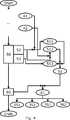
Dabei zeigt
BezugszeichenlisteLIST OF REFERENCE NUMBERS
- 1010
- Illuminieren des Objektes Illuminate the object
- 1111
- Illuminationssequenz Illumination sequence
- 1212
- Illumination der Illuminationssequenz Illumination of the illumination sequence
- 2020
- Erstellen eines Illuminationsbildes Create an illumination picture
- 2121
- Illuminationsbild Illumination image
- 2323
- Zwischenbild bezüglich der ersten Achse Intermediate image with respect to the first axis
- 2424
- Zwischenbild bezüglich der zweiten Achse Intermediate image with respect to the second axis
- 3030
- überlagern von zwei Illuminationsbildern overlay two illumination pictures
- 3131
- erstes Gesamtachsenbild first overall axis image
- 3232
- zweites Gesamtachsenbild second overall axis image
- 3333
- verrechnen von zwei Illuminationsbildern zu einem Zwischenbild Compute two illumination images to an intermediate image
- 3434
- verrechnen von Zwischenbildern zu einem Gesamtachsenbild Compute intermediate images to a total axis image
- 3535
- erste Achse first axis
- 3636
- zweite Achse second axis
- 4040
- Erstellen eines Farbverlaufsbildes Create a gradient image
- 4141
- erstes Farbverlaufsbild first gradient image
- 4242
- zweites Farbverlaufsbild second color gradient image
- 5050
- Transformieren der Farbverlaufsbilder in einen Farbraum Transform the gradient images into a color space
- 5151
- Farbraum color space
- 5252
- Zuweisen eines Farbverlaufsbildes zu einem bildgebenden Kanal des Farbraumes Assigning a color gradient image to an imaging channel of the color space
- 5353
- Zuweisen einer weiteren Information zu dem dritten bildgebenden Kanal des Farbraumes Assigning further information to the third imaging channel of the color space
- 6060
- Generieren eines Kontrastbildes Generate a contrast image
- 6161
- Kontrastbild contrast image
- 100100
- kontrastbildende Vorrichtung contrast-forming device
- 110110
- Bildaufnahmevorrichtung Imaging device
- 111111
- Illuminationsquelle Illumination source
- 120120
- Kontrastbildungsvorrichtung Contrast forming device
- 351 351
- erste Richtungsinformation des Höhenverlaufes first direction information of the height profile
- 352352
- zweite Richtungsinformation des Höhenverlaufes second direction information of the altitude profile
- 361361
- dritte Richtungsinformation des Höhenverlaufes third direction information of the height profile
- 362362
- vierte Richtungsinformation des Höhenverlaufes Fourth direction information of the height profile
- 511511
- erster bildgebender Kanal des Farbraumes first imaging channel of the color space
- 512512
- zweiter bildgebender Kanal des Farbraumes second imaging channel of the color space
- 513513
- dritter bildgebender Kanal des Farbraumes third color space imaging channel
ZITATE ENTHALTEN IN DER BESCHREIBUNG QUOTES INCLUDE IN THE DESCRIPTION
Diese Liste der vom Anmelder aufgeführten Dokumente wurde automatisiert erzeugt und ist ausschließlich zur besseren Information des Lesers aufgenommen. Die Liste ist nicht Bestandteil der deutschen Patent- bzw. Gebrauchsmusteranmeldung. Das DPMA übernimmt keinerlei Haftung für etwaige Fehler oder Auslassungen.This list of the documents listed by the applicant has been generated automatically and is included solely for the better information of the reader. The list is not part of the German patent or utility model application. The DPMA assumes no liability for any errors or omissions.
Zitierte Nicht-PatentliteraturCited non-patent literature
- EN ISO 11664-4[0024]EN ISO 11664-4[0024]
Claims (14)
Translated fromGermanPriority Applications (5)
| Application Number | Priority Date | Filing Date | Title |
|---|---|---|---|
| DE102015208084.6ADE102015208084A1 (en) | 2015-04-30 | 2015-04-30 | Method for generating a contrast image of an object condition and related devices |
| EP16167216.7AEP3089105A1 (en) | 2015-04-30 | 2016-04-27 | Method for generating a contrast image of an object quality and related devices |
| JP2016091060AJP2016212412A (en) | 2015-04-30 | 2016-04-28 | Method of generating contrast image of object structure, and related devices |
| CN201610277879.3ACN106097288B (en) | 2015-04-30 | 2016-04-28 | Method for generating contrast images of object structures and related device |
| US15/142,269US10175468B2 (en) | 2015-04-30 | 2016-04-29 | Method for generating a contrast image of an object structure and apparatuses relating thereto |
Applications Claiming Priority (1)
| Application Number | Priority Date | Filing Date | Title |
|---|---|---|---|
| DE102015208084.6ADE102015208084A1 (en) | 2015-04-30 | 2015-04-30 | Method for generating a contrast image of an object condition and related devices |
Publications (1)
| Publication Number | Publication Date |
|---|---|
| DE102015208084A1true DE102015208084A1 (en) | 2016-11-03 |
Family
ID=56068636
Family Applications (1)
| Application Number | Title | Priority Date | Filing Date |
|---|---|---|---|
| DE102015208084.6APendingDE102015208084A1 (en) | 2015-04-30 | 2015-04-30 | Method for generating a contrast image of an object condition and related devices |
Country Status (5)
| Country | Link |
|---|---|
| US (1) | US10175468B2 (en) |
| EP (1) | EP3089105A1 (en) |
| JP (1) | JP2016212412A (en) |
| CN (1) | CN106097288B (en) |
| DE (1) | DE102015208084A1 (en) |
Families Citing this family (2)
| Publication number | Priority date | Publication date | Assignee | Title |
|---|---|---|---|---|
| US10365465B2 (en)* | 2015-05-04 | 2019-07-30 | Versitech Limited | Apparatus and method for quantitative phase-gradient chirped-wavelength-encoded optical imaging |
| DE102018114005A1 (en)* | 2018-06-12 | 2019-12-12 | Carl Zeiss Jena Gmbh | Material testing of optical specimens |
Family Cites Families (8)
| Publication number | Priority date | Publication date | Assignee | Title |
|---|---|---|---|---|
| GB0606788D0 (en)* | 2006-04-03 | 2006-05-10 | Ind Co Ltd | Confocal microscopy |
| US8794072B2 (en)* | 2007-10-10 | 2014-08-05 | Sonoscan, Inc. | Scanning acoustic microscope with profilometer function |
| US8150125B2 (en)* | 2007-10-29 | 2012-04-03 | Siemens Medical Solutions Usa, Inc. | System for visualizing regions of interest in medical images |
| JP5646906B2 (en)* | 2010-08-06 | 2014-12-24 | キヤノン株式会社 | X-ray apparatus and X-ray measuring method |
| DE102011052721A1 (en)* | 2011-08-16 | 2013-02-21 | Hseb Dresden Gmbh | Measuring method for height profiles of surfaces |
| US8885941B2 (en)* | 2011-09-16 | 2014-11-11 | Adobe Systems Incorporated | System and method for estimating spatially varying defocus blur in a digital image |
| DE102013003900A1 (en)* | 2012-03-28 | 2013-10-02 | Carl Zeiss Microscopy Gmbh | Light microscope and method for image acquisition with a light microscope |
| US9001399B2 (en)* | 2013-03-13 | 2015-04-07 | Xerox Corporation | Automatically compensating for color differences from side 1 to side 2 of a document scanning device |
- 2015
- 2015-04-30DEDE102015208084.6Apatent/DE102015208084A1/enactivePending
- 2016
- 2016-04-27EPEP16167216.7Apatent/EP3089105A1/ennot_activeCeased
- 2016-04-28CNCN201610277879.3Apatent/CN106097288B/enactiveActive
- 2016-04-28JPJP2016091060Apatent/JP2016212412A/enactivePending
- 2016-04-29USUS15/142,269patent/US10175468B2/enactiveActive
Non-Patent Citations (4)
| Title |
|---|
| EN ISO 11664-4 |
| H. Su, Z. Yin, S. Huh, T. Kanade: Cell Segmentation via Spectral Analysis on Phase Retardation Features. In: 2013 IEEE 10th International Symposium on Biomedical Imaging - From Nano to Macro, 2013, S.1469-1475* |
| H. Su, Z. Yin, S. Huh, T. Kanade: Cell Segmentation via Spectral Analysis on Phase Retardation Features. In: 2013 IEEE 10th International Symposium on Biomedical Imaging – From Nano to Macro, 2013, S.1469-1475 |
| L.Tian, J. Wang, L. Waller: 3D differential phase-contrast microscopy with computational illumination using an LED array. In: Optics Letters, Vol.39, No.5 (2014), S.1326-1329* |
Also Published As
| Publication number | Publication date |
|---|---|
| EP3089105A1 (en) | 2016-11-02 |
| US10175468B2 (en) | 2019-01-08 |
| JP2016212412A (en) | 2016-12-15 |
| US20160320603A1 (en) | 2016-11-03 |
| CN106097288B (en) | 2020-12-04 |
| CN106097288A (en) | 2016-11-09 |
Similar Documents
| Publication | Publication Date | Title |
|---|---|---|
| EP3289398B1 (en) | Method for generating a reflection-reduced contrast image and corresponding devices | |
| DE69022584T2 (en) | METHOD FOR DERIVING NOISE REDUCTION ESTIMATES OF COLOR SIGNAL PARAMETERS FROM MULTIPLE COLOR / BRIGHTNESS IMAGE SENSOR OUTPUTS. | |
| DE112015000917T5 (en) | Image processing apparatus, image processing method and image processing program | |
| DE102011106072A1 (en) | SHADOW REMOVAL IN A PICTURE BASED ON A VEHICLE-BASED CAMERA USING AN OPTIMIZED LINEAR AXIS | |
| EP3089106B1 (en) | Method for reflection adjustment of images and related apparatus | |
| DE102009041757A1 (en) | Device and method for the proof of origin and authorship of images | |
| DE102011086318A1 (en) | Position determination of an object by detection of a position pattern by optical sensor | |
| EP2147346B1 (en) | Device and method for compensating color displacements in fiber optic imaging systems | |
| WO2015155070A1 (en) | Method and sensor for generating and detecting patterns on a surface | |
| DE102009023722A1 (en) | Method for determination and evaluation of contact pattern of teeth flank of gear wheel tooth, involves transforming color image in to binary image, and comparing binary image with reference criteria based on comparison criteria | |
| DE102016100134A1 (en) | A method and apparatus for inspecting an object using machine vision | |
| DE102015208084A1 (en) | Method for generating a contrast image of an object condition and related devices | |
| DE10126546A1 (en) | Arrangement for determining position-dependent intensity and color profile and/or focus profile of optical lens systems has measurement fields arranged in both dimensions of test image | |
| DE102005024949A1 (en) | Volume data sets e.g. computer tomography volume data sets, structures representation method, involves determining color and opacity values of allocation instruction from position coordinates at one position | |
| EP1206123B1 (en) | Method for false color representation of image data | |
| DE102012100848B4 (en) | System and method for the stereoscopic display of images of an endoscope | |
| DE102015112411A1 (en) | System for the stereoscopic display of images of an endoscope | |
| DE102009057724B4 (en) | Image capture device and method for reducing motion blur | |
| DE102009001521B4 (en) | Method for generating an HDR video image sequence | |
| DE102021130505B4 (en) | Method for determining an illumination color, image processing device and recording system | |
| DE102009058605A1 (en) | Method and device for increasing the contrast of a gray scale image | |
| EP3762870B1 (en) | Distance-measuring element | |
| DE102021124010A1 (en) | Method and device for videoendoscopy with fluorescent light | |
| DE102015202922A1 (en) | Apparatus and method for camera-based calculation of an aspect ratio of fingers of a hand | |
| DE102012023443A1 (en) | Device for detecting surface structure and photography of object to be examined, has detecting unit designed such that device enables detection of characteristics and allows evaluation of image information relative to z-axis in color space |
Legal Events
| Date | Code | Title | Description |
|---|---|---|---|
| R163 | Identified publications notified | ||
| R012 | Request for examination validly filed |