DE102015207150A1 - Hollow needle for an ophthalmological instrument - Google Patents
Hollow needle for an ophthalmological instrumentDownload PDFInfo
- Publication number
- DE102015207150A1 DE102015207150A1DE102015207150.2ADE102015207150ADE102015207150A1DE 102015207150 A1DE102015207150 A1DE 102015207150A1DE 102015207150 ADE102015207150 ADE 102015207150ADE 102015207150 A1DE102015207150 A1DE 102015207150A1
- Authority
- DE
- Germany
- Prior art keywords
- hollow needle
- suction channel
- needle according
- needle head
- proximal end
- Prior art date
- Legal status (The legal status is an assumption and is not a legal conclusion. Google has not performed a legal analysis and makes no representation as to the accuracy of the status listed.)
- Ceased
Links
- 238000001727in vivoMethods0.000claimsabstractdescription6
- 230000008878couplingEffects0.000claimsabstractdescription4
- 238000010168coupling processMethods0.000claimsabstractdescription4
- 238000005859coupling reactionMethods0.000claimsabstractdescription4
- 238000002604ultrasonographyMethods0.000claimsabstractdescription4
- 241000219739LensSpecies0.000description26
- 238000013467fragmentationMethods0.000description11
- 238000006062fragmentation reactionMethods0.000description11
- 230000006378damageEffects0.000description6
- 208000002177CataractDiseases0.000description3
- 208000027418Wounds and injuryDiseases0.000description2
- 238000010276constructionMethods0.000description2
- 208000014674injuryDiseases0.000description2
- 238000000034methodMethods0.000description2
- 238000001356surgical procedureMethods0.000description2
- BUHVIAUBTBOHAG-FOYDDCNASA-N(2r,3r,4s,5r)-2-[6-[[2-(3,5-dimethoxyphenyl)-2-(2-methylphenyl)ethyl]amino]purin-9-yl]-5-(hydroxymethyl)oxolane-3,4-diolChemical compoundCOC1=CC(OC)=CC(C(CNC=2C=3N=CN(C=3N=CN=2)[C@H]2[C@@H]([C@H](O)[C@@H](CO)O2)O)C=2C(=CC=CC=2)C)=C1BUHVIAUBTBOHAG-FOYDDCNASA-N0.000description1
- 235000014647Lens culinaris subsp culinarisNutrition0.000description1
- 230000015572biosynthetic processEffects0.000description1
- 230000007748combinatorial effectEffects0.000description1
- 238000011161developmentMethods0.000description1
- 230000018109developmental processEffects0.000description1
- 230000000694effectsEffects0.000description1
- 239000007788liquidSubstances0.000description1
- 230000005855radiationEffects0.000description1
Images


Classifications
- A—HUMAN NECESSITIES
- A61—MEDICAL OR VETERINARY SCIENCE; HYGIENE
- A61F—FILTERS IMPLANTABLE INTO BLOOD VESSELS; PROSTHESES; DEVICES PROVIDING PATENCY TO, OR PREVENTING COLLAPSING OF, TUBULAR STRUCTURES OF THE BODY, e.g. STENTS; ORTHOPAEDIC, NURSING OR CONTRACEPTIVE DEVICES; FOMENTATION; TREATMENT OR PROTECTION OF EYES OR EARS; BANDAGES, DRESSINGS OR ABSORBENT PADS; FIRST-AID KITS
- A61F9/00—Methods or devices for treatment of the eyes; Devices for putting in contact-lenses; Devices to correct squinting; Apparatus to guide the blind; Protective devices for the eyes, carried on the body or in the hand
- A61F9/007—Methods or devices for eye surgery
- A61F9/00736—Instruments for removal of intra-ocular material or intra-ocular injection, e.g. cataract instruments
- A61F9/00745—Instruments for removal of intra-ocular material or intra-ocular injection, e.g. cataract instruments using mechanical vibrations, e.g. ultrasonic
- A—HUMAN NECESSITIES
- A61—MEDICAL OR VETERINARY SCIENCE; HYGIENE
- A61B—DIAGNOSIS; SURGERY; IDENTIFICATION
- A61B2217/00—General characteristics of surgical instruments
- A61B2217/002—Auxiliary appliance
- A61B2217/005—Auxiliary appliance with suction drainage system
Landscapes
- Health & Medical Sciences (AREA)
- Ophthalmology & Optometry (AREA)
- Heart & Thoracic Surgery (AREA)
- Surgery (AREA)
- Engineering & Computer Science (AREA)
- Biomedical Technology (AREA)
- Nuclear Medicine, Radiotherapy & Molecular Imaging (AREA)
- Vascular Medicine (AREA)
- Life Sciences & Earth Sciences (AREA)
- Animal Behavior & Ethology (AREA)
- General Health & Medical Sciences (AREA)
- Public Health (AREA)
- Veterinary Medicine (AREA)
- Surgical Instruments (AREA)
- Infusion, Injection, And Reservoir Apparatuses (AREA)
Abstract
Translated fromGermanDescription
Translated fromGermanDie Erfindung betrifft eine Hohlnadel für ein augenchirurgisches Instrument zur in-vivo-Zertrümmerung organischer Linsen mittels Ultraschall, mit einem am proximalen Ende ausgebildeten Anschlussbereich zum Ankoppeln an das Instrument und einem am distalen Ende ausgebildeten Nadelkopf mit einer Wirkfläche zum Abstrahlen von Ultraschallwellen, wobei sich in Axialrichtung ein Absaugkanal zum Absaugen von Linsentrümmern durch die Hohlnadel hindurch erstreckt, dessen Öffnung durch die Wirkfläche begrenzt ist.The invention relates to a hollow needle for an ophthalmological instrument for in vivo disintegration of organic lenses by means of ultrasound, with a connection area formed at the proximal end for coupling to the instrument and a distal end formed needle head with an effective surface for emitting ultrasonic waves, wherein in Axialrichtung a suction passage for sucking Linsentrümmern through the hollow needle extends through, the opening is limited by the active surface.
Hohlnadeln der in Rede stehenden Art sind seit Jahren aus der Praxis bekannt. Eine entsprechende Hohlnadel ist in der
Des Weiteren zeigt die
Ultraschallbetätigte Hohlnadeln der gattungsbildenden Art werden bei Kataraktoperationen in der Augenchirurgie verwendet. Das freie Ende der Hohlnadel wird in eine hochfrequente Bewegung versetzt und unmittelbar an den Katarakt herangeführt. Vom ringförmigen Stirnende werden Ultraschallwellen zur Emulsifikation des Gewebes abgestrahlt. Abgetrennte Linsenteile bzw. Linsentrümmer werden durch die Hohlnadel hindurch gemeinsam mit einer dem Auge zugeführten Spülflüssigkeit abgeführt.Ultrasound-operated hollow needles of the generic type are used in cataract surgery in ophthalmic surgery. The free end of the hollow needle is placed in a high-frequency movement and brought directly to the cataract. From the annular front end ultrasonic waves are emitted to emulsify the tissue. Separated lens parts or lens debris are discharged through the hollow needle together with a rinsing liquid supplied to the eye.
Zur Verstärkung des emittierten Ultraschallfeldes ist es bereits bekannt, das stirnseitige bzw. distale Ende der Hohlnadel, d.h. die dortige Wirkfläche, gezahnt auszugestalten. Die zum Abstrahlen von Ultraschallwellen dienende Wirkfläche wird dadurch vergrößert, so dass die Effizienz des Instruments bzw. der Hohlnadel verbessert ist.In order to amplify the emitted ultrasonic field, it is already known that the end or distal end of the hollow needle, i. the local effective area, toothed design. The effective area for emitting ultrasonic waves is thereby increased, so that the efficiency of the instrument or the hollow needle is improved.
Die bekannten Hohlnadeln sind in der Praxis jedoch problematisch, da die Zertrümmerung der Linsen nur sehr langsam erfolgt. Um die Belastung durch den Eingriff für den Patienten möglichst gering zu halten, ist man jedoch bemüht, die Dauer des Eingriffs zu minimieren. Des Weiteren ist problematisch, dass bei der gattungsbildenden Hohlnadel mitunter größere Linsentrümmer abgesaugt werden, die sodann den Absaugkanal verstopfen und in diesem nur sehr langsam weiter zerkleinert werden.However, the known hollow needles are problematic in practice, since the fragmentation of the lenses takes place only very slowly. However, in order to minimize the burden of the procedure on the patient, efforts are made to minimize the duration of the procedure. Furthermore, it is problematic that in the generic hollow needle sometimes larger lens debris are sucked, which then clog the suction and are shredded in this very slowly.
Der vorliegenden Erfindung liegt daher die Aufgabe zugrunde, eine Hohlnadel für ein augenchirurgisches Instrument der gattungsbildenden Art derart auszugestalten und weiterzubilden, dass mit konstruktiv einfachen Mitteln in kurzer Zeit eine effektive Zertrümmerung organischer Linsen ermöglicht ist.The present invention is therefore based on the object, a hollow needle for an ophthalmological instrument of the generic type to design and further develop that with structurally simple means in a short time effective fragmentation of organic lenses is possible.
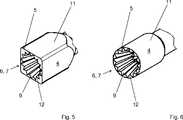
Erfindungsgemäß wird die voranstehende Aufgabe durch die Merkmale des Anspruches 1 gelöst. Danach ist die in Rede stehende Hohlnadel für ein augenchirurgisches Instrument zur in-vivo-Zertrümmerung organischer Linsen dadurch gekennzeichnet, dass der Absaugkanal im Nadelkopf zumindest bereichsweise in Richtung des proximalen Endes konisch zulaufend ausgebildet ist und dass über diesen Bereich hinweg in Axialrichtung verlaufende Einschnitte in der Wandung des Absaugkanals ausgebildet sind.According to the invention the above object is achieved by the features of claim 1. Thereafter, the question in question hollow needle for an ophthalmological instrument for in vivo fragmentation of organic lenses characterized in that the suction channel is at least partially conically formed in the needle head in the direction of the proximal end and that extending over this range in the axial direction incisions in the Wall of the suction channel are formed.
In erfindungsgemäßer Weise ist dabei zunächst erkannt worden, dass die zugrundeliegende Aufgabe durch eine geschickte Ausgestaltung der Geometrie des Absaugkanals im Nadelkopf gelöst werden kann. Dazu ist der Absaugkanal im Nadelkopf zumindest bereichsweise in Richtung des proximalen Endes konisch zulaufend ausgebildet, so dass sich der Durchmesser des Absaugkanals im Nadelkopf in Richtung des proximalen Endes verringert. Somit sind innerhalb des Absaugkanals keine radial verlaufenden Stufen bzw. Kanten vorhanden, an denen Linsentrümmer hängen bleiben und somit den Absaugkanal verstopfen. In weiter erfindungsgemäßer Weise ist erkannt worden, dass die Zertrümmerung der Linsen in verblüffend einfacher Weise verbessert werden kann, indem die Wandung des Absaugkanals über den gesamten konisch zulaufenden Bereich hinweg axial verlaufende Einschnitte aufweist. Durch diese einfache konstruktive Maßnahme ist die Abstrahlung der Ultraschallwellen optimiert, so dass eine verbesserte Zertrümmerung organischer Linsen möglich ist. Dabei wird durch die konische Ausgestaltung des Absaugkanals und die in dem konischen Bereich angeordneten Einschnitte ein kombinatorischer Effekt realisiert, der zu einer besonders schnellen und sicheren Zertrümmerung des Linsengewebes führt.In accordance with the invention, it has first been recognized that the underlying problem can be solved by a clever design of the geometry of the suction channel in the needle head. For this purpose, the suction channel in the needle head is designed to taper at least in regions in the direction of the proximal end, so that the diameter of the suction channel in the needle head is reduced in the direction of the proximal end. Thus, no radially extending steps or edges are present within the suction channel, where lentil debris get stuck and thus clog the suction channel. In a further inventive manner has been recognized that the fragmentation of the lenses can be improved in a surprisingly simple manner by the wall of the suction channel over the entire conically tapered region has axially extending cuts. By this simple design measure, the radiation of the ultrasonic waves is optimized, so that an improved fragmentation of organic lenses is possible. In this case, a combinatorial effect is realized by the conical configuration of the suction channel and arranged in the conical region incisions, which leads to a particularly rapid and secure destruction of the lens tissue.
Zweckmäßigerweise können unmittelbar am distalen Ende des Nadelkopfes in der Wandung des Absaugkanals, insbesondere tetraederförmige, Ausnehmungen ausgebildet sein. Dabei können die Ausnehmungen in Umfangsrichtung, beispielsweise radialsymmetrisch, angeordnet sein. Der Durchmesser des Absaugkanals kann in diesem Bereich zusätzlich vergrößert sein. Diese Ausgestaltung bietet den Vorteil, dass unmittelbar am distalen Ende der Hohlnadel die Abstrahlung der Ultraschallwellen maximiert ist, was die Effektivität der Zertrümmerung verbessert.Appropriately, recesses may be formed directly at the distal end of the needle head in the wall of the suction channel, in particular tetrahedral. The recesses may be arranged in the circumferential direction, for example radially symmetrical. The diameter of the suction channel can be additionally increased in this area. This embodiment offers the advantage that directly at the distal end of the hollow needle the emission of the ultrasonic waves is maximized, which improves the effectiveness of the fragmentation.
Im Konkreten können die Einschnitte einen mehreckigen Querschnitt aufweisen. Beispielsweise können die Einschnitte einen dreieckigen Querschnitt aufweisen, so dass diese besonders einfach herstellbar sind. Durch diese konstruktive Maßnahme ist zwischen den Einschnitten eine zahnartige Struktur in der Wandung des Absaugkanals realisiert, die sich zur Zerkleinerung besonders harter Linsenteile eignet.Specifically, the cuts may have a polygonal cross-section. For example, the incisions may have a triangular cross section, so that they are particularly easy to produce. By this constructive measure, a tooth-like structure is realized in the wall of the suction channel between the incisions, which is suitable for crushing particularly hard lens parts.
Je nach Härte der zu zertrümmernden Linse können die Einschnitte in Umfangsrichtung radialsymmetrisch oder asymmetrisch angeordnet sein.Depending on the hardness of the lens to be crushed, the incisions may be arranged radially symmetrically or asymmetrically in the circumferential direction.
In vorteilhafter Weise kann sich der konisch zulaufende Bereich durch einen Teil des Nadelkopfes hindurch erstrecken. Des Weiteren ist denkbar, dass sich der konisch zulaufende Bereich durch den gesamten Nadelkopf erstreckt, so dass eine maximale Fläche zur Abstrahlung von Ultraschallwellen realisiert ist.Advantageously, the tapered portion may extend through a portion of the needle head. Furthermore, it is conceivable that the conically tapered region extends through the entire needle head, so that a maximum surface for the emission of ultrasonic waves is realized.
In weiter vorteilhafter Weise kann der konisch zulaufende Bereich unmittelbar am distalen Ende der Hohlnadel beginnen, so dass eingesaugte Linsentrümmer bereits zu Beginn des Absaugkanals mit einem Maximum an Ultraschallwellen beaufschlagt werden. Sofern am distalen Ende des Absaugkanals Ausnehmungen vorgesehen sind, kann der konisch zulaufende Bereich unmittelbar nach den Ausnehmungen beginnen. Des Weiteren ist denkbar, dass der konisch zulaufende Bereich versetzt vom distalen Ende, d.h. in Richtung des proximalen Endes, beginnt. Eine solche Konstruktion eignet sich zur besonders schonenden Zerstörung der Linse.In a further advantageous manner, the conically tapering region can begin directly at the distal end of the hollow needle, so that aspirated lens debris are already subjected to a maximum of ultrasonic waves at the beginning of the suction channel. If recesses are provided at the distal end of the suction channel, the conically tapered region can begin immediately after the recesses. Furthermore, it is conceivable that the tapered portion is offset from the distal end, i. towards the proximal end, begins. Such a construction is suitable for the particularly gentle destruction of the lens.
Um den sog. „jack hammer-Anteil“, d.h. die Effektivität der Hohlnadel, weiter zu erhöhen, können die Einschnitte in Richtung des proximalen Endes über den konisch zulaufenden Bereich hinaus verlaufen. Zur Verstärkung dieses Effektes ist des Weiteren denkbar, dass die äußere Wandung des Nadelkopfes vieleckig, beispielsweise vier-, fünf-, sechs- oder achteckig, ausgebildet ist. Zur Schonung des Gewebes, das um die zu zertrümmernde Linse liegt, kann die äußere Wandung des Nadelkopfes rund ausgebildet sein.To the so-called "jack hammer share", i. To further increase the effectiveness of the hollow needle, the incisions may extend beyond the tapered region in the direction of the proximal end. To reinforce this effect is further conceivable that the outer wall of the needle head polygonal, for example, four, five, six or octagonal, is formed. To protect the tissue, which is located around the lens to be smashed, the outer wall of the needle head may be round.
Um die Wirkfläche zu vergrößern, kann diese schräg zu der Axialrichtung verlaufen. Des Weiteren ist denkbar, dass die Wirkfläche senkrecht zu der Axialrichtung verläuft, um somit das umliegende Gewebe vor Verletzungen zu schützen.To increase the effective area, this can extend obliquely to the axial direction. Furthermore, it is conceivable that the active surface is perpendicular to the axial direction, so as to protect the surrounding tissue from injury.
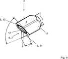
In besonders vorteilhafter Weise weist die Wirkfläche zwei in unterschiedlichen Winkeln gegenüber der Axialrichtung verlaufende Wirkflächenbereiche auf, so dass die Wirkfläche schnabelartig ausgebildet ist. Durch die schnabelartige Geometrie ist eine äußerst effektive und konzentrierte Abstrahlung von Ultraschallwellen möglich, so dass auch harte Bereiche der zu zertrümmernden Linse, beispielsweise ein bereits längere Zeit existierender Katarakt, zügig zerstört werden.In a particularly advantageous manner, the active surface has two active surface regions extending at different angles relative to the axial direction, so that the active surface is beak-shaped. Due to the beak-like geometry, an extremely effective and concentrated emission of ultrasonic waves is possible, so that even hard areas of the lens to be smashed, for example a cataract that already exists for a long time, are rapidly destroyed.
In weiter vorteilhafter Weise ist die Wirkfläche durch eine äußere Kante begrenzt, wobei die äußere Kante angefast, stumpf oder scharf ausgebildet sein kann. Eine angefaste bzw. stumpfe Ausbildung der Kante dient zur Vermeidung von Verletzungen des umliegenden Gewebes. Durch eine scharfe Ausgestaltung der äußeren Kante ist eine besonders effektive Zertrümmerung der Linse möglich.In a further advantageous manner, the active surface is limited by an outer edge, wherein the outer edge may be chamfered, dull or sharp. A chamfered or blunt formation of the edge serves to avoid injuries to the surrounding tissue. By a sharp configuration of the outer edge a particularly effective fragmentation of the lens is possible.
Es gibt nun verschiedene Möglichkeiten, die Lehre der vorliegenden Erfindung in vorteilhafter Weise auszugestalten und weiterzubilden. Dazu ist einerseits auf die dem Anspruch 1 nachgeordneten Ansprüche und andererseits auf die nachfolgende Erläuterung bevorzugter Ausführungsbeispiele der Erfindung anhand der Zeichnung zu verweisen. In Verbindung mit der Erläuterung der bevorzugten Ausführungsbeispiele der Erfindung anhand der Zeichnung werden auch im Allgemeinen bevorzugte Ausgestaltungen und Weiterbildungen der Lehre erläutert. In der Zeichnung zeigenThere are now various possibilities for designing and developing the teaching of the present invention in an advantageous manner. For this purpose, on the one hand to the claims subordinate to claim 1 and on the other hand to refer to the following explanation of preferred embodiments of the invention with reference to the drawings. In conjunction with the explanation of the preferred embodiments of the invention with reference to the drawings, also generally preferred embodiments and developments of the teaching are explained. In the drawing show
Der Absaugkanal
Die äußere Wandung
Hinsichtlich weiterer vorteilhafter Ausgestaltungen der erfindungsgemäßen Vorrichtung wird zur Vermeidung von Wiederholungen auf den allgemeinen Teil der Beschreibung sowie auf die beigefügten Ansprüche verwiesen.With regard to further advantageous embodiments of the device according to the invention, reference is made to avoid repetition to the general part of the specification and to the appended claims.
Schließlich sei ausdrücklich darauf hingewiesen, dass die voranstehend beschriebenen Ausführungsbeispiele der erfindungsgemäßen Vorrichtung lediglich zur Erörterung der beanspruchten Lehre dienen, diese jedoch nicht auf die Ausführungsbeispiele einschränken.Finally, it should be expressly understood that the above-described embodiments of the device according to the invention are only for the purpose of discussion of the claimed teaching, but not limit these to the embodiments.
BezugszeichenlisteLIST OF REFERENCE NUMBERS
- 11
- proximales Endeproximal end
- 22
- Anschlussbereichterminal area
- 33
- distales Endedistal end
- 44
- Nadelkopfpinhead
- 55
- Wirkflächeeffective area
- 66
- Absaugkanalsuction
- 77
- Öffnungopening
- 88th
- konischer Bereichconical area
- 99
- Einschnittecuts
- 1010
- Wandung (Absaugkanal)Wall (suction channel)
- 1111
- äußere Wandungouter wall
- 1212
- Zähneteeth
- 1313
- erster Wirkflächenbereichfirst effective area area
- 1414
- zweiter Wirkflächenbereichsecond active surface area
ZITATE ENTHALTEN IN DER BESCHREIBUNG QUOTES INCLUDE IN THE DESCRIPTION
Diese Liste der vom Anmelder aufgeführten Dokumente wurde automatisiert erzeugt und ist ausschließlich zur besseren Information des Lesers aufgenommen. Die Liste ist nicht Bestandteil der deutschen Patent- bzw. Gebrauchsmusteranmeldung. Das DPMA übernimmt keinerlei Haftung für etwaige Fehler oder Auslassungen.This list of the documents listed by the applicant has been generated automatically and is included solely for the better information of the reader. The list is not part of the German patent or utility model application. The DPMA assumes no liability for any errors or omissions.
Zitierte PatentliteraturCited patent literature
- US 6074396 A[0002]US 6074396 A[0002]
- DE 19646881 C1[0003]DE 19646881 C1[0003]
Claims (10)
Translated fromGermanPriority Applications (8)
| Application Number | Priority Date | Filing Date | Title |
|---|---|---|---|
| DE102015207150.2ADE102015207150A1 (en) | 2015-04-20 | 2015-04-20 | Hollow needle for an ophthalmological instrument |
| CN201680035702.0ACN107750152B (en) | 2015-04-20 | 2016-02-02 | Hollow needle for an ophthalmic surgical instrument |
| JP2017555600AJP2018516639A (en) | 2015-04-20 | 2016-02-02 | Hollow needle for ophthalmic surgical instruments |
| EP16709262.6AEP3128967B1 (en) | 2015-04-20 | 2016-02-02 | Hollow needle for an ophthalmic surgical instrument |
| BR112017022313-9ABR112017022313B1 (en) | 2015-04-20 | 2016-02-02 | HOLLOW NEEDLE FOR AN OPHTHALMIC SURGICAL INSTRUMENT |
| PCT/DE2016/200063WO2016169556A1 (en) | 2015-04-20 | 2016-02-02 | Hollow needle for an ophthalmic surgical instrument |
| AU2016251271AAU2016251271B2 (en) | 2015-04-20 | 2016-02-02 | Hollow needle for an ophthalmic surgical instrument |
| US15/568,170US10675182B2 (en) | 2015-04-20 | 2016-02-02 | Hollow needle for an ophthalmic surgical instrument |
Applications Claiming Priority (1)
| Application Number | Priority Date | Filing Date | Title |
|---|---|---|---|
| DE102015207150.2ADE102015207150A1 (en) | 2015-04-20 | 2015-04-20 | Hollow needle for an ophthalmological instrument |
Publications (1)
| Publication Number | Publication Date |
|---|---|
| DE102015207150A1true DE102015207150A1 (en) | 2016-11-03 |
Family
ID=55524037
Family Applications (1)
| Application Number | Title | Priority Date | Filing Date |
|---|---|---|---|
| DE102015207150.2ACeasedDE102015207150A1 (en) | 2015-04-20 | 2015-04-20 | Hollow needle for an ophthalmological instrument |
Country Status (8)
| Country | Link |
|---|---|
| US (1) | US10675182B2 (en) |
| EP (1) | EP3128967B1 (en) |
| JP (1) | JP2018516639A (en) |
| CN (1) | CN107750152B (en) |
| AU (1) | AU2016251271B2 (en) |
| BR (1) | BR112017022313B1 (en) |
| DE (1) | DE102015207150A1 (en) |
| WO (1) | WO2016169556A1 (en) |
Cited By (5)
| Publication number | Priority date | Publication date | Assignee | Title |
|---|---|---|---|---|
| WO2018224100A1 (en)* | 2017-06-07 | 2018-12-13 | Geuder Ag | Hollow needle for an ophthalmic surgical instrument |
| WO2019191632A1 (en)* | 2018-03-30 | 2019-10-03 | Surgical Design Corporation | Phaco cone work tip for a surgical hand-piece |
| US11369513B2 (en) | 2017-11-22 | 2022-06-28 | Surgical Design Corporation | Low-cost disposable ultrasonic surgical handpiece |
| US11504271B2 (en) | 2018-03-30 | 2022-11-22 | Surgical Design Corporation | Surgical hand-piece with a bottom fluid tube convertible from irrigation to aspiration |
| US11690757B2 (en) | 2018-03-30 | 2023-07-04 | Surgical Design Corporation | Surgical hand piece with post-occlusion surge elimination |
Families Citing this family (1)
| Publication number | Priority date | Publication date | Assignee | Title |
|---|---|---|---|---|
| US20200038242A1 (en)* | 2018-08-06 | 2020-02-06 | Nallakrishnan Family Trust | Apparatus and method for phacoemulsification |
Citations (5)
| Publication number | Priority date | Publication date | Assignee | Title |
|---|---|---|---|---|
| DE19628252A1 (en)* | 1996-07-12 | 1998-01-15 | Jochen Dr Med Kammann | Probe for removal of eye tissue |
| DE19646881C1 (en) | 1996-11-13 | 1998-08-20 | Volker Geuder | Hollow needle for surgical ophthalmic instrument |
| US20120197215A1 (en)* | 2008-10-31 | 2012-08-02 | Takayuki Akahoshi | Apparatus and Method for Phacoemulsification |
| EP2737884A1 (en)* | 2012-12-03 | 2014-06-04 | Cesar C. Dr. Carriazo | Medical hollow needle |
| US20140243842A1 (en)* | 2011-08-03 | 2014-08-28 | Nigel Morlet | Grooved needle tip for surgical instrument |
Family Cites Families (6)
| Publication number | Priority date | Publication date | Assignee | Title |
|---|---|---|---|---|
| JPH0746247Y2 (en)* | 1989-12-04 | 1995-10-25 | 公也 清水 | Tip structure of surgical equipment using ultrasonic vibration energy |
| US8016843B2 (en)* | 2005-09-09 | 2011-09-13 | Alcon Research Ltd | Ultrasonic knife |
| US20090099536A1 (en)* | 2006-11-06 | 2009-04-16 | Takayuki Akahoshi Akahoshi | Bidirectional Phacoemulsification Needle Tips for Torsional and Longitudinal Motion |
| CN101401755B (en)* | 2007-09-28 | 2013-01-23 | 株式会社尼德克 | Head for ultrasonic operation and knife head for ultrasonic operation |
| JP2009240622A (en)* | 2008-03-31 | 2009-10-22 | Hideharu Fukasaku | Phacoemulsification chip |
| JP5679085B2 (en)* | 2014-10-04 | 2015-03-04 | Jmr株式会社 | Lens for ultrasonic emulsion suction |
- 2015
- 2015-04-20DEDE102015207150.2Apatent/DE102015207150A1/ennot_activeCeased
- 2016
- 2016-02-02AUAU2016251271Apatent/AU2016251271B2/enactiveActive
- 2016-02-02CNCN201680035702.0Apatent/CN107750152B/enactiveActive
- 2016-02-02BRBR112017022313-9Apatent/BR112017022313B1/enactiveIP Right Grant
- 2016-02-02EPEP16709262.6Apatent/EP3128967B1/enactiveActive
- 2016-02-02USUS15/568,170patent/US10675182B2/enactiveActive
- 2016-02-02WOPCT/DE2016/200063patent/WO2016169556A1/ennot_activeCeased
- 2016-02-02JPJP2017555600Apatent/JP2018516639A/enactivePending
Patent Citations (6)
| Publication number | Priority date | Publication date | Assignee | Title |
|---|---|---|---|---|
| DE19628252A1 (en)* | 1996-07-12 | 1998-01-15 | Jochen Dr Med Kammann | Probe for removal of eye tissue |
| DE19646881C1 (en) | 1996-11-13 | 1998-08-20 | Volker Geuder | Hollow needle for surgical ophthalmic instrument |
| US6074396A (en) | 1996-11-13 | 2000-06-13 | Geuder; Volker | Hollow needle for an ophthalmic surgical instrument |
| US20120197215A1 (en)* | 2008-10-31 | 2012-08-02 | Takayuki Akahoshi | Apparatus and Method for Phacoemulsification |
| US20140243842A1 (en)* | 2011-08-03 | 2014-08-28 | Nigel Morlet | Grooved needle tip for surgical instrument |
| EP2737884A1 (en)* | 2012-12-03 | 2014-06-04 | Cesar C. Dr. Carriazo | Medical hollow needle |
Cited By (6)
| Publication number | Priority date | Publication date | Assignee | Title |
|---|---|---|---|---|
| WO2018224100A1 (en)* | 2017-06-07 | 2018-12-13 | Geuder Ag | Hollow needle for an ophthalmic surgical instrument |
| US11369513B2 (en) | 2017-11-22 | 2022-06-28 | Surgical Design Corporation | Low-cost disposable ultrasonic surgical handpiece |
| WO2019191632A1 (en)* | 2018-03-30 | 2019-10-03 | Surgical Design Corporation | Phaco cone work tip for a surgical hand-piece |
| US11207212B2 (en) | 2018-03-30 | 2021-12-28 | Surgical Design Corporation | Phaco cone work tip for a surgical hand-piece |
| US11504271B2 (en) | 2018-03-30 | 2022-11-22 | Surgical Design Corporation | Surgical hand-piece with a bottom fluid tube convertible from irrigation to aspiration |
| US11690757B2 (en) | 2018-03-30 | 2023-07-04 | Surgical Design Corporation | Surgical hand piece with post-occlusion surge elimination |
Also Published As
| Publication number | Publication date |
|---|---|
| BR112017022313A2 (en) | 2018-07-03 |
| US10675182B2 (en) | 2020-06-09 |
| AU2016251271A1 (en) | 2017-11-30 |
| CN107750152A (en) | 2018-03-02 |
| EP3128967B1 (en) | 2018-12-26 |
| CN107750152B (en) | 2020-07-03 |
| US20180110649A1 (en) | 2018-04-26 |
| WO2016169556A1 (en) | 2016-10-27 |
| JP2018516639A (en) | 2018-06-28 |
| EP3128967A1 (en) | 2017-02-15 |
| BR112017022313B1 (en) | 2022-10-11 |
| AU2016251271B2 (en) | 2020-02-20 |
Similar Documents
| Publication | Publication Date | Title |
|---|---|---|
| EP3128967B1 (en) | Hollow needle for an ophthalmic surgical instrument | |
| DE19646881C1 (en) | Hollow needle for surgical ophthalmic instrument | |
| EP3041443B1 (en) | Surgical instrument | |
| EP2273958B1 (en) | Hollow needle for an ophthalmic surgical instrument | |
| EP2521518A1 (en) | Apparatus for cutting and aspirating tissue | |
| DE102012106017A1 (en) | Applicator and device for cell treatment | |
| DE4313245A1 (en) | Hollow needle for an instrument for eye surgery | |
| DE112020004710T5 (en) | ULTRASOUND PROBE | |
| DE112020004001T5 (en) | ULTRASOUND PROBE | |
| AT410055B (en) | LASER SCALPEL | |
| DE102017221017A1 (en) | Device for cutting and aspirating tissue from the human or animal eye | |
| EP3626213A1 (en) | Surgical instrument, surgical device and electronic control device | |
| DE602004000355T2 (en) | phacoemulsification needle | |
| DE102014219616A1 (en) | Device for cutting tissue | |
| EP3197408A1 (en) | Hollow needle for an ophthalmic surgical instrument | |
| DE102018200971B4 (en) | Hollow needle for an ophthalmic surgical instrument and a sheath surrounding the hollow needle | |
| EP2582336B1 (en) | Hollow needle for an ophthalmological instrument | |
| EP2737884B1 (en) | Medical hollow needle | |
| EP3634326B1 (en) | Hollow needle for an ophthalmic surgical instrument | |
| DE202013006687U1 (en) | Device for endoscopic resection in the upper or lower gastrointestinal tract | |
| DE102017214679B3 (en) | Ophthalmic hand-held device and sonotrode for an ophthalmic hand-held device | |
| DE102022204957A1 (en) | Hand-held ophthalmological device and method for adjusting a hand-held ophthalmological device | |
| EP0640316A1 (en) | Probe for intracorporal fragmentation of stones | |
| DE202010010594U1 (en) | Medical hand instrument, in particular trocar lance, and trocar system | |
| DE102019205703A1 (en) | Medical instrument for drilling cortex |
Legal Events
| Date | Code | Title | Description |
|---|---|---|---|
| R012 | Request for examination validly filed | ||
| R002 | Refusal decision in examination/registration proceedings | ||
| R003 | Refusal decision now final |