DE102015204957A1 - Imaging tomosynthesis system, in particular mammography system - Google Patents
Imaging tomosynthesis system, in particular mammography systemDownload PDFInfo
- Publication number
- DE102015204957A1 DE102015204957A1DE102015204957.4ADE102015204957ADE102015204957A1DE 102015204957 A1DE102015204957 A1DE 102015204957A1DE 102015204957 ADE102015204957 ADE 102015204957ADE 102015204957 A1DE102015204957 A1DE 102015204957A1
- Authority
- DE
- Germany
- Prior art keywords
- density values
- values
- density
- tomosynthesis system
- height
- Prior art date
- Legal status (The legal status is an assumption and is not a legal conclusion. Google has not performed a legal analysis and makes no representation as to the accuracy of the status listed.)
- Pending
Links
Images


Classifications
- G—PHYSICS
- G06—COMPUTING OR CALCULATING; COUNTING
- G06T—IMAGE DATA PROCESSING OR GENERATION, IN GENERAL
- G06T7/00—Image analysis
- G06T7/0002—Inspection of images, e.g. flaw detection
- G06T7/0012—Biomedical image inspection
- A—HUMAN NECESSITIES
- A61—MEDICAL OR VETERINARY SCIENCE; HYGIENE
- A61B—DIAGNOSIS; SURGERY; IDENTIFICATION
- A61B6/00—Apparatus or devices for radiation diagnosis; Apparatus or devices for radiation diagnosis combined with radiation therapy equipment
- A61B6/02—Arrangements for diagnosis sequentially in different planes; Stereoscopic radiation diagnosis
- A61B6/025—Tomosynthesis
- A—HUMAN NECESSITIES
- A61—MEDICAL OR VETERINARY SCIENCE; HYGIENE
- A61B—DIAGNOSIS; SURGERY; IDENTIFICATION
- A61B6/00—Apparatus or devices for radiation diagnosis; Apparatus or devices for radiation diagnosis combined with radiation therapy equipment
- A61B6/50—Apparatus or devices for radiation diagnosis; Apparatus or devices for radiation diagnosis combined with radiation therapy equipment specially adapted for specific body parts; specially adapted for specific clinical applications
- A61B6/502—Apparatus or devices for radiation diagnosis; Apparatus or devices for radiation diagnosis combined with radiation therapy equipment specially adapted for specific body parts; specially adapted for specific clinical applications for diagnosis of breast, i.e. mammography
- A—HUMAN NECESSITIES
- A61—MEDICAL OR VETERINARY SCIENCE; HYGIENE
- A61B—DIAGNOSIS; SURGERY; IDENTIFICATION
- A61B6/00—Apparatus or devices for radiation diagnosis; Apparatus or devices for radiation diagnosis combined with radiation therapy equipment
- A61B6/52—Devices using data or image processing specially adapted for radiation diagnosis
- A61B6/5205—Devices using data or image processing specially adapted for radiation diagnosis involving processing of raw data to produce diagnostic data
- G—PHYSICS
- G06—COMPUTING OR CALCULATING; COUNTING
- G06T—IMAGE DATA PROCESSING OR GENERATION, IN GENERAL
- G06T11/00—2D [Two Dimensional] image generation
- G06T11/003—Reconstruction from projections, e.g. tomography
- G06T11/006—Inverse problem, transformation from projection-space into object-space, e.g. transform methods, back-projection, algebraic methods
- G—PHYSICS
- G06—COMPUTING OR CALCULATING; COUNTING
- G06T—IMAGE DATA PROCESSING OR GENERATION, IN GENERAL
- G06T11/00—2D [Two Dimensional] image generation
- G06T11/003—Reconstruction from projections, e.g. tomography
- G06T11/008—Specific post-processing after tomographic reconstruction, e.g. voxelisation, metal artifact correction
- G—PHYSICS
- G09—EDUCATION; CRYPTOGRAPHY; DISPLAY; ADVERTISING; SEALS
- G09G—ARRANGEMENTS OR CIRCUITS FOR CONTROL OF INDICATING DEVICES USING STATIC MEANS TO PRESENT VARIABLE INFORMATION
- G09G5/00—Control arrangements or circuits for visual indicators common to cathode-ray tube indicators and other visual indicators
- G09G5/02—Control arrangements or circuits for visual indicators common to cathode-ray tube indicators and other visual indicators characterised by the way in which colour is displayed
- H—ELECTRICITY
- H04—ELECTRIC COMMUNICATION TECHNIQUE
- H04N—PICTORIAL COMMUNICATION, e.g. TELEVISION
- H04N1/00—Scanning, transmission or reproduction of documents or the like, e.g. facsimile transmission; Details thereof
- H04N1/46—Colour picture communication systems
- H04N1/56—Processing of colour picture signals
- H04N1/60—Colour correction or control
- H04N1/6027—Correction or control of colour gradation or colour contrast
- A—HUMAN NECESSITIES
- A61—MEDICAL OR VETERINARY SCIENCE; HYGIENE
- A61B—DIAGNOSIS; SURGERY; IDENTIFICATION
- A61B6/00—Apparatus or devices for radiation diagnosis; Apparatus or devices for radiation diagnosis combined with radiation therapy equipment
- A61B6/02—Arrangements for diagnosis sequentially in different planes; Stereoscopic radiation diagnosis
- A61B6/03—Computed tomography [CT]
- A61B6/032—Transmission computed tomography [CT]
- A—HUMAN NECESSITIES
- A61—MEDICAL OR VETERINARY SCIENCE; HYGIENE
- A61B—DIAGNOSIS; SURGERY; IDENTIFICATION
- A61B6/00—Apparatus or devices for radiation diagnosis; Apparatus or devices for radiation diagnosis combined with radiation therapy equipment
- A61B6/12—Arrangements for detecting or locating foreign bodies
- A—HUMAN NECESSITIES
- A61—MEDICAL OR VETERINARY SCIENCE; HYGIENE
- A61B—DIAGNOSIS; SURGERY; IDENTIFICATION
- A61B6/00—Apparatus or devices for radiation diagnosis; Apparatus or devices for radiation diagnosis combined with radiation therapy equipment
- A61B6/46—Arrangements for interfacing with the operator or the patient
- A61B6/461—Displaying means of special interest
- A61B6/463—Displaying means of special interest characterised by displaying multiple images or images and diagnostic data on one display
- A—HUMAN NECESSITIES
- A61—MEDICAL OR VETERINARY SCIENCE; HYGIENE
- A61B—DIAGNOSIS; SURGERY; IDENTIFICATION
- A61B6/00—Apparatus or devices for radiation diagnosis; Apparatus or devices for radiation diagnosis combined with radiation therapy equipment
- A61B6/52—Devices using data or image processing specially adapted for radiation diagnosis
- A61B6/5211—Devices using data or image processing specially adapted for radiation diagnosis involving processing of medical diagnostic data
- A61B6/5217—Devices using data or image processing specially adapted for radiation diagnosis involving processing of medical diagnostic data extracting a diagnostic or physiological parameter from medical diagnostic data
- G—PHYSICS
- G06—COMPUTING OR CALCULATING; COUNTING
- G06T—IMAGE DATA PROCESSING OR GENERATION, IN GENERAL
- G06T2200/00—Indexing scheme for image data processing or generation, in general
- G06T2200/24—Indexing scheme for image data processing or generation, in general involving graphical user interfaces [GUIs]
- G—PHYSICS
- G06—COMPUTING OR CALCULATING; COUNTING
- G06T—IMAGE DATA PROCESSING OR GENERATION, IN GENERAL
- G06T2207/00—Indexing scheme for image analysis or image enhancement
- G06T2207/10—Image acquisition modality
- G06T2207/10072—Tomographic images
- G06T2207/10112—Digital tomosynthesis [DTS]
- G—PHYSICS
- G06—COMPUTING OR CALCULATING; COUNTING
- G06T—IMAGE DATA PROCESSING OR GENERATION, IN GENERAL
- G06T2207/00—Indexing scheme for image analysis or image enhancement
- G06T2207/20—Special algorithmic details
- G06T2207/20036—Morphological image processing
- G06T2207/20041—Distance transform
- G—PHYSICS
- G06—COMPUTING OR CALCULATING; COUNTING
- G06T—IMAGE DATA PROCESSING OR GENERATION, IN GENERAL
- G06T2207/00—Indexing scheme for image analysis or image enhancement
- G06T2207/20—Special algorithmic details
- G06T2207/20212—Image combination
- G06T2207/20221—Image fusion; Image merging
- G—PHYSICS
- G06—COMPUTING OR CALCULATING; COUNTING
- G06T—IMAGE DATA PROCESSING OR GENERATION, IN GENERAL
- G06T2207/00—Indexing scheme for image analysis or image enhancement
- G06T2207/30—Subject of image; Context of image processing
- G06T2207/30004—Biomedical image processing
- G06T2207/30068—Mammography; Breast
- G—PHYSICS
- G06—COMPUTING OR CALCULATING; COUNTING
- G06T—IMAGE DATA PROCESSING OR GENERATION, IN GENERAL
- G06T2207/00—Indexing scheme for image analysis or image enhancement
- G06T2207/30—Subject of image; Context of image processing
- G06T2207/30196—Human being; Person
- G—PHYSICS
- G06—COMPUTING OR CALCULATING; COUNTING
- G06T—IMAGE DATA PROCESSING OR GENERATION, IN GENERAL
- G06T2210/00—Indexing scheme for image generation or computer graphics
- G06T2210/41—Medical
- G—PHYSICS
- G06—COMPUTING OR CALCULATING; COUNTING
- G06T—IMAGE DATA PROCESSING OR GENERATION, IN GENERAL
- G06T2211/00—Image generation
- G06T2211/40—Computed tomography
- G06T2211/424—Iterative
- G—PHYSICS
- G06—COMPUTING OR CALCULATING; COUNTING
- G06T—IMAGE DATA PROCESSING OR GENERATION, IN GENERAL
- G06T2211/00—Image generation
- G06T2211/40—Computed tomography
- G06T2211/436—Limited angle
- G—PHYSICS
- G09—EDUCATION; CRYPTOGRAPHY; DISPLAY; ADVERTISING; SEALS
- G09G—ARRANGEMENTS OR CIRCUITS FOR CONTROL OF INDICATING DEVICES USING STATIC MEANS TO PRESENT VARIABLE INFORMATION
- G09G2300/00—Aspects of the constitution of display devices
- G09G2300/04—Structural and physical details of display devices
- G09G2300/0439—Pixel structures
- G09G2300/0452—Details of colour pixel setup, e.g. pixel composed of a red, a blue and two green components
- G—PHYSICS
- G09—EDUCATION; CRYPTOGRAPHY; DISPLAY; ADVERTISING; SEALS
- G09G—ARRANGEMENTS OR CIRCUITS FOR CONTROL OF INDICATING DEVICES USING STATIC MEANS TO PRESENT VARIABLE INFORMATION
- G09G2340/00—Aspects of display data processing
- G09G2340/08—Monochrome to colour transformation
- G—PHYSICS
- G09—EDUCATION; CRYPTOGRAPHY; DISPLAY; ADVERTISING; SEALS
- G09G—ARRANGEMENTS OR CIRCUITS FOR CONTROL OF INDICATING DEVICES USING STATIC MEANS TO PRESENT VARIABLE INFORMATION
- G09G2380/00—Specific applications
- G09G2380/08—Biomedical applications
Landscapes
- Engineering & Computer Science (AREA)
- Health & Medical Sciences (AREA)
- Life Sciences & Earth Sciences (AREA)
- Physics & Mathematics (AREA)
- Medical Informatics (AREA)
- Theoretical Computer Science (AREA)
- Nuclear Medicine, Radiotherapy & Molecular Imaging (AREA)
- General Physics & Mathematics (AREA)
- General Health & Medical Sciences (AREA)
- Radiology & Medical Imaging (AREA)
- Molecular Biology (AREA)
- Surgery (AREA)
- Pathology (AREA)
- High Energy & Nuclear Physics (AREA)
- Biomedical Technology (AREA)
- Heart & Thoracic Surgery (AREA)
- Biophysics (AREA)
- Optics & Photonics (AREA)
- Animal Behavior & Ethology (AREA)
- Veterinary Medicine (AREA)
- Public Health (AREA)
- Computer Vision & Pattern Recognition (AREA)
- Computer Hardware Design (AREA)
- Oral & Maxillofacial Surgery (AREA)
- Dentistry (AREA)
- Quality & Reliability (AREA)
- Mathematical Physics (AREA)
- Pure & Applied Mathematics (AREA)
- Multimedia (AREA)
- Mathematical Optimization (AREA)
- Mathematical Analysis (AREA)
- Signal Processing (AREA)
- Algebra (AREA)
- Apparatus For Radiation Diagnosis (AREA)
- Pulmonology (AREA)
Abstract
Translated fromGermanDescription
Translated fromGermanDie Erfindung betrifft ein bildgebendes Tomosynthesesystem, insbesondere ein Mammographiesystem, mit einem Strahler-Detektor-System zur Abtastung eines Untersuchungsobjektes aus mehreren Projektionswinkeln, die zur Erzeugung tomosynthetischer Bilddaten des Untersuchungsobjektes geeignet sind und einem Computersystem mit zumindest einer Anzeigeeinheit und einem Speicher zur Abspeicherung von Programmen, welche zumindest eine tomosynthetische Rekonstruktion ausführen.The invention relates to an imaging tomosynthesis system, in particular a mammography system, with a radiator-detector system for scanning an examination object from a plurality of projection angles, which are suitable for generating tomosynthetic image data of the examination subject and a computer system with at least one display unit and a memory for storing programs, which perform at least one tomosynthetic reconstruction.
Die Röntgentechnik hat sich in der medizinischen Diagnostik als ein Standardverfahren etabliert. Sie basiert darauf, dass durch ein Objekt Röntgenstrahlen entsprechend der Absorptionseigenschaften des Objektes abgeschwächt werden. Die Intensität der das Objekt durchdringenden Röntgenstrahlen wird mittels eines ortsauflösenden Detektors gemessen und zur Intensität der Röntgenstrahlen ohne Objekt ins Verhältnis gesetzt. Die so aufgenommenen Intensitätsänderungen stellen in Abhängigkeit der Aufnahmegeometrie ein Maß dar, welches insbesondere eine Aussage über die Dichte des von den Röntgenstrahlen durchdrungenen Gewebes liefert.X-ray technology has become established as a standard procedure in medical diagnostics. It is based on the fact that X-rays are attenuated by an object according to the absorption properties of the object. The intensity of the X-rays penetrating the object is measured by means of a spatially resolving detector and related to the intensity of the X-rays without an object. The thus recorded intensity changes represent a measure depending on the recording geometry, which in particular provides information about the density of the tissue penetrated by the X-rays.
Die traditionelle Röntgentechnik liefert typischerweise Projektionsbilder in zwei Dimensionen, die mittels eines Flächendetektors aufgenommen wurden. Eine Auflösung orthogonal zu der Detektorfläche ist herkömmlich jedoch nicht möglich. Im Zuge der Weiterentwicklung der Röntgentechnik wurden Verfahren entwickelt, die auch Informationen bezüglich der dritten Dimension liefern. Diese Verfahren basieren darauf, dass Röntgenprojektionen aus einer Vielzahl von verschiedenen Projektionsrichtungen aufgenommen werden und aus den dadurch erhaltenen Schwächungsdaten – auch Projektionen genannt – dreidimensional in Voxel aufgelöste Dichtewerte des Objektes rekonstruiert werden. Diese Voxel werden meist mit den Dichtewerten entsprechenden Grauwerten ausgegeben und können für die Analyse des Objektes verwendet werden, z.B. indem Schnitte des Objektes berechnet und dargestellt werden.Traditional X-ray technology typically provides projection images in two dimensions taken using a surface detector. However, a resolution orthogonal to the detector surface is not possible conventionally. In the course of further development of X-ray technology, methods have been developed that also provide information regarding the third dimension. These methods are based on the fact that X-ray projections are recorded from a multiplicity of different projection directions and the resulting attenuation data - also called projections - three-dimensional density values of the object resolved in voxels are reconstructed. These voxels are usually output with gray levels corresponding to the density values and can be used for the analysis of the object, e.g. by calculating and displaying sections of the object.
Die erste Röntgenmodalität, welche die Rekonstruktion eines Volumendatensatzes ermöglichte, war die Computertomographie. Zur Ermittlung von Projektionsdaten wird hierbei meist eine Röntgenquelle mit einem gegenüberliegenden Detektor um ein dazwischen liegendes Objekt oder einen Patienten rotiert und aus den so gewonnenen Projektionsdaten über einen Winkelbereich von 360°, mindestens jedoch 180° zuzüglich dem Fächerwinkel des Strahler-Detektor-Systems, tomographische Schnittbilder senkrecht zur Rotationsachse rekonstruiert. Inzwischen existiert eine Reihe von anderen Röntgengeräten, die ebenfalls eine dreidimensionale Rekonstruktion zulassen, z.B. C-Bögen und Mammographiegeräte. Während C-Bogensysteme noch die zur tomographischen Rekonstruktion notwendige Abtastung über einen Projektionswinkelbereich von 180° plus Fächerwinkel ermöglichen, werden bei Mammographie-Systemen zur Winkelbereiche von deutlich unter 180° abgetastet. Zur 3D-Rekonstruktion aus Projektionsdaten von Mammographie-Systemen wird entsprechend der geringeren Abtastinformation eine Rekonstruktion nach dem Tomosyntheseverfahren ausgeführt. Aufgrund der reduzierten Abtastinformation entstehen Bilddaten mit gegenüber der Computertomographie etwas geringerer Güte.The first X-ray modality that enabled the reconstruction of a volumetric data set was computed tomography. In order to determine projection data, an x-ray source with an opposing detector is usually rotated about an object or a patient lying therebetween, and the projection data thus obtained are tomographic over an angular range of 360 °, but at least 180 ° plus the fan angle of the radiator-detector system Cross-sectional images reconstructed perpendicular to the axis of rotation. Meanwhile, there are a number of other X-ray machines which also allow three-dimensional reconstruction, e.g. C-arms and mammography devices. While C-arm systems still allow the scanning necessary for tomographic reconstruction over a projection angle range of 180 ° plus fan angle, in mammography systems the angle ranges of well below 180 ° are scanned. For 3D reconstruction from projection data of mammography systems, a reconstruction according to the tomosynthesis method is carried out in accordance with the lower sampling information. Due to the reduced sampling information, image data are produced with a slightly lower quality compared to computed tomography.
Insbesondere in der Mammographie ergeben sich für die Darstellung von durch Tomosynthese gewonnenen Datensätzen besondere Herausforderungen, die einerseits daraus resultieren, dass nur mit einem beschränkten Winkelbereich und damit artefaktbehafteten Volumendaten gearbeitet wird, und zum anderen daraus, dass relevante darzustellende Strukturen, sogenannte Mikrokalzifizierungen, die kanzerogenes Gewebe indizieren, eine sehr geringe Größe aufweisen.Particularly in mammography, the presentation of data sets obtained by tomosynthesis presents particular challenges, resulting, on the one hand, from working only with a limited angular range and thus artifact volume data and, second, from the fact that the relevant structures to be displayed, so-called microcalcifications, are the carcinogenic Index tissue, have a very small size.
Daher ist es gebräuchlich, die herkömmlich durch Tomosynthese erhaltenen Gewebedarstellungen durch andere, zusätzliche Darstellungen zu ergänzen, um so die Diagnose zu verbessern bzw. zu erleichtern. Beispielsweise können zusätzliche Aufnahmen, beispielsweise mittels digitaler Mammographie oder full-field digital mammography (FFDM)) gemacht werden. Häufig verzichtet man auch zugunsten einer niedrigeren Röntgendosis auf die zusätzlichen Aufnahmen und rekonstruiert stattdessen zusätzliche Aufnahmen aus den durch Tomosynthese gewonnenen Volumendaten. In diesen Zusammenhang spricht man auch von berechneten, synthetischen Mammographieaufnahmen oder Mammogrammen.Therefore, it is customary to supplement the tissue representations conventionally obtained by tomosynthesis with other additional representations so as to improve the diagnosis. For example, additional recordings can be made, for example by means of digital mammography or full-field digital mammography (FFDM). Frequently, one also dispenses with the additional recordings in favor of a lower X-ray dose and instead reconstructs additional recordings from the volume data obtained by tomosynthesis. In this context we also speak of calculated, synthetic mammographic images or mammograms.
Ein synthetisches Mammogramm kann für einen Aufnahmewinkel (typischerweise 0°) oder für eine Vielzahl von Aufnahmewinkeln (man spricht hier auch von einem „rotierenden Mammogramm“) angefertigt werden. Bei der Anfertigung eines synthetischen Mammogramms muss nicht notwendigerweise eine Integration bzw. Aufsummierung der Volumendaten entlang von Sehstrahlen (auch als „DRR“ für den englischen Ausdruck „digitally reconstucted radiograph“ bezeichnet) erfolgen. Es ist z.B. daneben als eine andere Technik auch die Maximumintensitätsprojektion (MIP, maximum intensity projection) als Verfahren der Bildverarbeitung üblich. Im Zuge der Maximumintensitätsprojektion werden dreidimensionale Volumendatensätze bzw. Bilddatensätze in zweidimensionale Projektionsbilder umgerechnet, indem entlang der Blickrichtung, also entlang der einzelnen Sehstrahlen in Projektionsrichtung, jeweils der Datenpunkt mit der maximalen Intensität ausgewählt wird. Ein Anwendungsbereich ist beispielsweise die Darstellung von CT-Angiographie- und Magnetresonanzangiographie-Daten. In diesen Daten haben die Blutgefäße im Allgemeinen hohe Signalintensitäten und werden daher durch die Maximumintensitätsprojektion gut sichtbar abgebildet. Ein derartiges Verfahren ist z.B. in der
Bei der Anfertigung von synthetischen Aufnahmen aus Volumendatensätzen ist es wünschenswert, dass der diagnostizierende Arzt eine möglichst aussagekräftige Darstellung der vielen für die Diagnose relevanten Informationen erhält. Die Anmeldung hat zur Aufgabe, hierzu einen Beitrag zu leisten.When making synthetic recordings from volume data records, it is desirable for the diagnosing physician to obtain the most meaningful representation possible of the many information relevant to the diagnosis. The application has the task to make a contribution to this.
Die Aufgabe wird gelöst durch ein bildgebendes Tomosynthesesystem, insbesondere ein Mammographiesystem gemäß einem der Patentansprüche.The object is achieved by an imaging tomosynthesis system, in particular a mammography system according to one of the claims.
Der Ausgangspunkt der Erfindung ist ein Vorgehen, bei welchem eine Rekonstruktion von Dichtewerten aus Röntgenaufnahmen eines Objekts durchgeführt wird. Dabei erfolgt eine Ermittlung eines Dichtewertes für die Darstellung des Objekts auf einer Anzeige, wobei im Zuge der Ermittlung ein Dichtewert entlang einer die rekonstruierten Dichtewerte durchlaufenden Geraden ausgewählt wird. Diese Auswahl eines Dichtewerts kann z.B. nach Maßgabe des Maximums der auf der Geraden liegenden Dichtewerte durchgeführt werden, so dass eine typische MIP-Darstellung (MIP = maximum intensity projection) erreicht wird. Dabei ist möglich, dass die Dichtewerte vor der Maximumsbestimmung bearbeiten werden, z.B. durch Vornahme einer Glättung, die durch Rauschen hervorgerufene Effekte unterdrückt.The starting point of the invention is a procedure in which a reconstruction of density values from X-ray images of an object is performed. In this case, a density value for the representation of the object is determined on a display, wherein in the course of the determination a density value is selected along a straight line passing through the reconstructed density values. This selection of a density value may e.g. in accordance with the maximum of the density values lying on the straight line, so that a typical MIP representation (MIP = maximum intensity projection) is achieved. It is possible that the density values will be processed before the maximum determination, e.g. by applying a smoothing that suppresses noise-induced effects.
Ein genereller Erfindungsgedanke basiert auf der Überlegung, dass bei den oben beschrieben Vorgehen die Position des ausgewählten Dichtewerts verwendet werden kann, um bei der Darstellung des Objekts zusätzliche Informationen zur Verfügung zu stellen, die die Interpretation des Ergebnisses erleichtern.A general inventive concept is based on the consideration that in the procedure described above, the position of the selected density value can be used to provide additional information in the representation of the object, which facilitate the interpretation of the result.
Erfindungsgemäß kann eine Positionsinformation für den ausgewählten Dichtewert ermittelt und für die Bereitstellung und optionalen Ausgabe auf der Anzeige, einer den Dichtewert betreffenden Information verwendet werden. Bei dieser Information kann es sich z.B. um die Positionsinformation selbst oder eine andere, mit Hilfe der Positionsinformation gewonnene Information handeln.According to the invention, position information for the selected density value can be determined and used for the provision and optional output on the display of information relating to the density value. This information may be e.g. to act the position information itself or another, obtained with the help of the position information information.
Die Positionsinformation kann ein Maß für die Entfernung zu einem virtuellen Betrachter, der z.B. durch einen Punkt oder eine Ebene definiert ist, darstellen. Vorzugsweise wird der virtuelle Betrachter durch den Fokuspunkt der verwendeten Röntgenröhre definiert. Dann entspricht die Entfernung der durch einen Röntgenstrahl auf der Geraden durchlaufenen Distanz zu der Position des ausgewählten Dichtewerts.The position information may be a measure of the distance to a virtual viewer, e.g. is defined by a point or a plane. Preferably, the virtual viewer is defined by the focal point of the x-ray tube used. Then, the distance of the distance traveled by an X-ray on the straight line corresponds to the position of the selected density value.
Im Zuge dieser ersten Ausgestaltung können der Dichtewert und die Positionsinformation in einem Pixel der Anzeige durch Kodierung in Werten eines für die Pixeldarstellung verwendeten Farbraums dargestellt werden. Dabei kann der Farbraum einen Farbwert und ein Helligkeitswert für die Darstellung eines Pixels vorsehen, so dass Farbwert und Helligkeitswert für die Kodierung von Dichtewert und Positionsinformation verwendet werden können.In the course of this first embodiment, the density value and the position information in a pixel of the display can be represented by encoding in values of a color space used for the pixel display. In this case, the color space can provide a color value and a brightness value for the representation of a pixel, so that color value and brightness value can be used for the coding of density value and position information.
Im Rahmen einer zweiten Ausgestaltung des Erfindungsgegenstandes gibt die Positionsinformation die Position des Dichtewertes in einem ortsfesten Koordinatensystem beziehungsweise einem Weltkoordinatensystem, dessen Ursprung z.B. in der Mitte des Detektors liegt, an.In the context of a second embodiment of the subject invention, the position information indicates the position of the density value in a fixed coordinate system or a world coordinate system whose origin is e.g. in the middle of the detector.
Die Ermittlung der Positionsinformation erfolgt beispielsweise, wenn durch einen Nutzer den auf der Anzeige angezeigten bzw. dargestellten Dichtewert anwählt (z.B. mittels Maus, wobei auf Anwahl ein lokales Extremum gesucht und als angewählter Dichtewert verwendet werden kann, um so Ungenauigkeiten einer händischen Eingabe zu kompensieren).The position information is determined, for example, when a user selects the density value displayed or displayed on the display (eg by means of a mouse, where a local extremum can be searched for and used as a selected density value in order to compensate for inaccuracies of a manual input) ,
Bei der zweiten Ausführungsform kann vorgesehen sein, dass eine Mehrzahl von Dichtewerten auf der Anzeige angezeigt werden und durch Anwahl von zwei Dichtewerten eine die beiden Dichtewerte betreffende Abstandsinformation bestimmt wird, welche z.B. auf der Anzeige angezeigt bzw. eingeblendet wird.In the second embodiment, it may be provided that a plurality of density values are displayed on the display, and by selecting two density values, a distance information concerning the two density values is determined, which is e.g. appears or appears on the display.
In einer Variante der zweiten Ausführungsform wird auf der Anzeige ein auf Basis von ermittelten Dichtewerten gebildetes Bild angezeigt. Es ist dann auf dem Bild ein Bereich von an- gezeigten Dichtewerten auswählbar, z.B. durch Einkreisen mittels Computermaus. Anschließend werden in dem Bereich Dichtewerte nach Maßgabe eines Kriteriums für die Höhe der Dichte, z.B. einem Schwellenwert, identifiziert. Dies kann entweder durch Rückgriff auf die Werte selbst oder mittels deren Pixelkodierung, z.B. bezüglich der Helligkeit des Pixels, erfolgen. Für die identifizierten Dichtewerte können die Positionsinformationen ermittelt werden. Die Positionsinformationen können verwendet werden, um in drei Dimensionen Begrenzungsflächen zu bestimmen, die die identifizierten Dichtewerte einschließen. Es wird dabei also eine Art Box oder eine beliebige, vorzugsweise durchgehend konkave und geschlossene Begrenzungsfläche gebildet, die die Dichtewerte umschließt. Die Begrenzungsflächen können für die Darstellung eines die identifizierten Dichtewerte enthaltenden Bereichs bei der Anzeige von mittels Auswahl entlang einer die rekonstruierten Dichtewerte durchlaufenden Geraden ermittelten Dichtewerten und/oder rekonstruierten Dichtewerten verwendet werden.In a variant of the second embodiment, an image formed on the basis of determined density values is displayed on the display. A range of displayed density values can then be selected in the image, for example by circling using a computer mouse. Subsequently, density values are identified in the region in accordance with a criterion for the height of the density, eg a threshold value. This can be done either by resorting to the values themselves or by means of their pixel coding, for example with regard to the brightness of the pixel. The position information can be determined for the identified density values. The position information can be used to determine bounding surfaces in three dimensions that include the identified density values. Thus, a kind of box or any, preferably continuous, concave and closed boundary surface is formed, which encloses the density values. The bounding surfaces may be used to represent one of the identified density values Range can be used in the display of density values and / or reconstructed density values determined by selection along a straight line passing through the reconstructed density values.
Beide Ausführungsformen können auch gemeinsam verwendet werden oder teilweise auf Elemente der jeweils anderen Ausführungsform zurückgreifen.Both embodiments may also be used in common or partially rely on elements of each other embodiment.
Entsprechend den oben geschilderten Grundgedanken schlagen die Erfinder ein bildgebendes Tomosynthesesystem, insbesondere ein Mammographiesystem, vor, welches aufweist:
- – ein Strahler-Detektor-System zur Abtastung eines Untersuchungsobjektes aus mehreren Projektionswinkeln, die zur Erzeugung tomosynthetischer Bilddaten des Untersuchungsobjektes geeignet sind,
- – ein Computersystem mit zumindest einer Anzeigeeinheit und einem Speicher zur Abspeicherung von Programmen, die derart gestaltet sind, dass sie im Betrieb folgendes Verfahren ausführen:
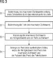
- – Erstellung von Röntgenprojektionen eines Untersuchungsobjektes mit einem Strahler-Detektor-System aus mehreren Projektionswinkeln, die zur Erzeugung tomosynthetischer Bilddaten aus Dichtewerten des Untersuchungsobjektes geeignet sind,
- – Rekonstruktion eines Stapels tomosynthetischer Schnittbilddaten, die sich jeweils in einer Ebene durch das Untersuchungsobjekt erstrecken und die Schnitten in unterschiedlichen Höhen, senkrecht zu den Ebenen, entsprechen, aus den Röntgenprojektionen,
- – Erzeugung eines Übersichtsbildes von Dichtewerten des Untersuchungsobjektes aus den tomosynthetischen Darstellungen,
- – Auswahl jeweils eines charakteristischen Dichtewertes im Stapel an mindestens einer Ebenenposition (= Bildposition in 2d-Raum der Schnittebene) der tomosynthetischen Schnittbilder,
- – Bestimmung der Höhe des mindestens einen ausgewählten charakteristischen Dichtewertes,
- – Darstellung des Übersichtsbildes aus Dichtewerten auf einer Anzeigevorrichtung und gleichzeitige Darstellung der Höhe des mindestens einen charakteristischen Dichtewertes als mit der Höhe korrelierten Farbwert.
- A radiator-detector system for scanning an examination object from a plurality of projection angles, which are suitable for generating tomosynthetic image data of the examination subject,
- A computer system having at least one display unit and a memory for storing programs designed to operate in the following manner:
- Creation of X-ray projections of an examination object with a radiator-detector system from a plurality of projection angles which are suitable for generating tomosynthetic image data from density values of the examination subject,
- Reconstruction of a stack of tomosynthetic sectional image data which in each case extend in a plane through the examination subject and which correspond to the sections at different heights, perpendicular to the planes, from the x-ray projections,
- Generation of an overview image of density values of the examination object from the tomosynthetic representations,
- Selection of a characteristic density value in the stack at at least one plane position (= image position in 2d space of the section plane) of the tomosynthetic sectional images,
- Determination of the height of the at least one selected characteristic density value,
- - Representation of the overview image of density values on a display device and simultaneous display of the height of the at least one characteristic density value as correlated with the height color value.
Zur Begriffsbestimmung ist anzumerken, dass unter der Ebenenposition die x/y-Koordinaten der tomosynthetischen Schnittbilder in der x/y-Ebene zu verstehen sind, die äquivalent zu der x/y-Ebene des Detektors oder des Übersichtsbildes sind. Außerdem wird unter Höhe des Dichtewertes der Wert der z-Koordinate verstanden, an der der Dichtewert im in z-Richtung übereinander gestapelten Bildstapel auftritt. In der einfachsten Form entspricht die Höhe der Nummer der tomosynthetischen Schnittebene eines durchnummerierten Stapels von tomosynthetischen Schnittbildern durch das Untersuchungsobjekt. Die x/y/z-Koordinaten werden dabei als Koordinaten eines orthogonalen Koordinatensystems angesehen.For definition, it should be noted that the plane position means the x / y coordinates of the tomosynthetic sectional images in the x / y plane that are equivalent to the x / y plane of the detector or the overview image. In addition, the value of the z coordinate at which the density value occurs in the stack of images stacked one above the other in the z direction is understood as the height value of the density value. In the simplest form, the height of the tomosynthetic sectional plane number corresponds to a numbered stack of tomosynthetic sectional images through the examination subject. The x / y / z coordinates are considered as coordinates of an orthogonal coordinate system.
Durch eine derartige gleichzeitige Darstellung eines zweidimensionalen virtuellen Übersichtsbildes von Dichtewerten eines Untersuchungsobjektes auf der Basis der tomosynthetischen Bilddaten kombiniert mit farblich dargestellten Höhenangaben (= z-Positionsangaben) charakteristischer Dichtewerte wird eine besonders übersichtliche und diagnostisch aussagekräftige Ansicht relevanter Dichtewerte aus einer tomosynthetischen Darstellung, insbesondere einer mammographischen Darstellung einer weiblichen Brust, erreicht.Such a concurrent representation of a two-dimensional virtual overview image of density values of an examination object on the basis of the tomosynthetic image data combined with color-coded height data (= z position information) characteristic density values is a particularly clear and diagnostically meaningful view of relevant density values from a tomosynthetic representation, in particular a mammographic Representation of a female breast, reached.
Vorteilhaft kann als Übersichtsbild eine, im Bereich virtuell erzeugter Übersichtsdarstellungen grundsätzlich bekannte, MIP-Darstellung (MIP = maximum intension projection) gewählt werden. Hierbei ist es besonders günstig, wenn auch der charakteristische Dichtewert nach dem MIP-Verfahren ausgewählt wird, also wenn die charakteristischen Dichtewerte die maximalen Dichtewerte an der jeweiligen Ebenenposition darstellen.Advantageously, an MIP representation (MIP = maximum intension projection) basically known in the area of virtually generated overview representations can be selected as the overview image. In this case, it is particularly favorable if the characteristic density value is also selected according to the MIP method, ie if the characteristic density values represent the maximum density values at the respective plane position.
Weiterhin kann es günstig sein, wenn ein Schaltelement vorliegt, welches die Ein- und Ausschaltung der Farbinformationen bezüglich der Höhe der charakteristischen Dichtewerte zur Verfügung stellt. Ein solches Schaltelement kann beispielsweise rein softwaretechnisch, z.B. als anzuklickender Button oder auch als mechanischer Schalter an der Anzeigevorrichtung oder der Bedienkonsole, gegebenenfalls in Verbindung mit einem Touchscreen realisiert werden.Furthermore, it may be favorable if a switching element is present, which provides the switching on and off of the color information with regard to the height of the characteristic density values. Such a switching element can, for example, purely software technology, e.g. as a button to be clicked or as a mechanical switch on the display device or the control panel, possibly in conjunction with a touch screen can be realized.
Besonders vorteilhaft kann es auch sein, wenn die Dichtewerte der Übersichtsdarstellung und die Höhe des mindestens einen charakteristischen Dichtewertes durch eine Kodierung in einem ausgewählten Farbraum dargestellt werden. Insbesondere können die Dichtewerte und die Höhe in einem Pixel durch Kodierung in Werten eines für die Pixeldarstellung verwendeten Farbraums dargestellt werden, wobei vorzugsweise Farbwerte und Helligkeitswerte für die Darstellung eines Pixels derart verwendet werden, dass der Dichte Helligkeitswerte und der Höhe Farbwerte zugeordnet sind. Als Farbraum kann insbesondere einer der Farbräume HSV-Farbraum, HSB-Farbraum oder HSI-Farbraum verwendet werden.It may also be particularly advantageous if the density values of the overview representation and the height of the at least one characteristic density value are represented by a coding in a selected color space. In particular, the density values and the height in a pixel can be represented by encoding in values of a color space used for the pixel representation, wherein color values and brightness values are preferably used for the representation of a pixel such that the brightness values are assigned to the density and color values to the height. In particular one of the color spaces HSV color space, HSB color space or HSI color space can be used as color space.
In einer weiteren Ausgestaltung des erfindungsgemäßen Tomosynthesesystems kann ausschließlich die Ebenenpositionen mit maximalen Dichtewerten über einem vorgegebenen Schwellwert mit der zusätzlichen Höheninformation dargestellt werden. Im Wesentlichen dient eine solche Ausgestaltung dazu, dass möglichst ausschließlich Mikrokalzifizierungen, die sich durch besonders hohe Dichtewerte auszeichnen explizit bezüglich ihrer Höhenposition eingefärbt werden, während andere weniger interessante Bereiche weiterhin nur mit Grauwerten angezeigt werden. Dies führt zu einer besonders übersichtlichen und auf die Kalzifizierungen fixierten Anzeige im Rahmen der Mammographie. Besonders vorteilhaft ist es dann noch, wenn das System eine Benutzerschnittstelle zur Verfügung stellt, mit der eine Beeinflussung beziehungsweise Eingabe des Schwellwertes ermöglicht wird. Eine solche Schnittstelle kann manuell verstellbares Potentiometer sein, oder auch ein auf der Anzeige dargestellter Schieberegler oder ähnliches. Alternativ gehört hierzu auch die Möglichkeit durch Anklicken von Dichtewerten auf der Anzeige den Schwellwert gemäß dem angeklickten Dichtewert einzustellen.In a further embodiment of the tomosynthesis system according to the invention, only the plane positions with maximum density values above a predetermined threshold value with the additional height information can be represented. In essence, such serves Embodiment to the fact that as possible only Microkalzifizierungen that are characterized by particularly high density values are explicitly colored with respect to their height position, while other less interesting areas continue to be displayed only with gray scale. This leads to a particularly clear and fixed on the calcifications display in the context of mammography. It is still particularly advantageous if the system provides a user interface with which an influencing or input of the threshold value is made possible. Such an interface may be manually adjustable potentiometer, or a slider or the like shown on the display. Alternatively, it is also possible to set the threshold value according to the selected density value by clicking on density values on the display.
In einer weiteren Ausgestaltung kann das Tomosynthesesystem mit einer Benutzerschnittstelle ausgestattet sein, welche es erlaubt, mindestens zwei Ebenenpositionen in der Übersichtsdarstellung gleichzeitig anzuwählen, wobei durch Anwahl von zwei Ebenenpositionen auf der mit charakteristischen Dichtewerten der dreidimensionale Abstand zwischen den räumlichen Positionen der charakteristischen Dichtewerte bestimmt und angezeigt wird.In a further embodiment, the tomosynthesis system can be equipped with a user interface which allows to simultaneously select at least two level positions in the overview display, whereby the three-dimensional distance between the spatial positions of the characteristic density values is determined and displayed by selecting two level positions on the one having characteristic density values becomes.
In einer nochmals weiteren Variante der Ausgestaltung des Tomosynthesesystems kann vorgesehen werden, dass auf der Übersichtsdarstellung ein Bereich von angezeigten Dichtewerten auswählbar ist, die in diesem Bereich vorliegenden Dichtewerte identifiziert werden, und in drei Dimensionen Begrenzungsflächen bestimmt werden, die die Positionen der identifizierten Dichtewerte einschließen. Werden solche Begrenzungsflächen in der Übersichtsdarstellung angezeigt, so lassen sich leicht Häufungen von Kalzifizierungen erkennen, die diagnostisch auf mögliche kanzerogene Entwicklungen hinweisen können.In yet another variant of the embodiment of the tomosynthesis system it can be provided that a range of displayed density values can be selected on the overview display, the density values present in this area are identified, and boundary surfaces are determined in three dimensions, which include the positions of the identified density values. If such boundary surfaces are displayed in the overview, it is easy to detect accumulations of calcifications, which can diagnostically indicate possible carcinogenic developments.
Vorteilhaft können dabei die Begrenzungsflächen für die Darstellung eines die identifizierten Dichtewerte enthaltenden Bereichs bei der Anzeige von mittels Auswahl entlang einer die rekonstruierten Dichtewerte durchlaufenden Geraden ermittelten Dichtewerten und/oder rekonstruierten Dichtewerten verwendet werden.Advantageously, the boundary surfaces for displaying a region containing the identified density values can be used in the display of density values and / or reconstructed density values determined by selection along a straight line passing through the reconstructed density values.
Grundsätzlich wird darauf hingewiesen, dass zum Rahmen der Erfindung auch das hier beschriebene Verfahren zur Verarbeitung von Bilddaten und deren Darstellung zählt, wobei ebenso ein Datenträger mit einem darauf geschriebenen Computerprogramm zur Erfindung zählt, welches im Betrieb die Schritte dieses Verfahrens ausführt.In principle, it is pointed out that the scope of the invention also includes the method described here for processing image data and its representation, whereby a data carrier with a computer program written on it counts as well as the invention, which performs the steps of this method during operation.
Die Erfindung wird im Folgenden anhand von Figuren im Rahmen von Ausführungsbeispielen näher erläutert. Hierbei werden die folgenden Bezugszeichen verwendet:
Es zeigen:Show it:
Die generelle Situation bei Tomosyntheseaufnahmen ist in
Aus den aufgenommenen Projektionen wird ein Volumendatensatz rekonstruiert. Dieser Volumendatensatz wird im Folgenden auch als DBT Volumen (DBT: digital breast tomosynthesis) bezeichnet. Übliche Rekonstruktionsverfahren sind die gefilterte Rückprojektion (FBP: Filtered Back Projection) z.B. mittels des Feldkamp-Algorithmus und iterative Verfahren. Der Volumendatensatz liegt üblicherweise in Form von Voxeln, die Raumpunkten zugeordnet sind, vor, die Dichtewerte darstellen, die meist als Grauwerte wiedergegeben werden. Für die Analyse erfolgt zumindest eine Abbildung dieser Dichtewert im Raum auf in zwei Dimensionen definierten Werte (häufig als Pixel bezeichnet), die zur Anzeige auf einem Monitor verwendet werden. Dabei wird typischerweise von Sehstrahlen ausgegangen. Aus den Werten des Volumendatensatzes entlang eines Sehstrahls wird ein Pixel zur Anzeige auf einem Monitor ermittelt.From the recorded projections, a volume data set is reconstructed. This volume data set is also referred to below as DBT volume (DBT: digital breast tomosynthesis). Conventional reconstruction methods are the filtered back projection (FBP: Filtered Back Projection), e.g. using the Feldkamp algorithm and iterative methods. The volume data set is usually in the form of voxels, which are assigned to spatial points, which represent density values, which are usually reproduced as gray values. For analysis, at least one mapping of this density value in space to values defined in two dimensions (often referred to as pixels) is performed, which are used for display on a monitor. This is typically assumed by visual rays. From the values of the volume data set along a line of sight, a pixel is determined for display on a monitor.
Die Erfindung geht davon aus, dass entlang der, den rekonstruierten Volumendatensatz durchdringenden, Sehstrahlen ein Dichtewert ausgewählt wird. Dabei kann es sich um das Dichtemaximum entlang des Strahles handeln (Maximumintensitätsprojektion bzw. MIP-Verfahren). Dies ist jedoch nicht zwingend erforderlich, es können auch andere Kriterien für die Auswahl des Dichtewertes gewählt werden. Es ist ausreichend, wenn einem ermittelten Dichtewert eine Position zugeordnet werden kann. Die ermittelten Dichtewerte fließen direkt oder in bearbeiteter Form in Pixel einer virtuellen Übersichtsdarstellung, also eines synthetischen Mammogramms, ein, welche auf einer Anzeige beziehungsweise einem Monitor anzeigt werden kann. Der Einfachheit halber wird im Folgenden die Erfindung für Maximumsintensitätsprojektionen (d.h. im Rahmen des MIP-Verfahrens) beschrieben.The invention assumes that a density value is selected along the visual rays penetrating the reconstructed volume data set. This can be the density maximum along the beam (maximum intensity projection or MIP method). However, this is not mandatory, other criteria for the selection of the density value can be selected. It is sufficient if a position can be assigned to a determined density value. The determined density values flow directly or in processed form into pixels of a virtual overview representation, ie of a synthetic mammogram, which can be displayed on a display or a monitor. For the sake of simplicity, the invention will be described below for maximum intensity projections (i.e., in the context of the MIP method).
Es werden zur besseren Darstellung die Variablen MIP-I(u,v) und MIP-D(u,v) eingeführt. Diese Variablen werden mittels des rekonstruierten DTB Volumens erzeugt und sind wie folgt definiert.For better illustration, the variables MIP-I (u, v) and MIP-D (u, v) are introduced. These variables are generated by means of the reconstructed DTB volume and are defined as follows.
MIP-I(u,v):R2 → R1 (I = Intensität): Der Algorithmus durchläuft einen Strahl von dem Fokus der für die Aufnahme verwendeten Röntgenröhre bis zur Projektionsebene des synthetischen Mammogramms durch das rekonstruierte Tomosynthesevolumen. Das dabei aufgefundene Voxel mit der maximalen Dichte bzw. Intensität wird als Pixelwert mit den Koordinaten – hier u,v, teilweise auch mit x,y benannt – verwendet, wobei die Koordinaten am Schnittpunkt des Strahles mit der Projektionsebene genommen sind.MIP-I (u, v): R2 → R1 (I = Intensity): The algorithm traverses a ray from the focus of the x-ray tube used for acquisition to the projection plane of the synthetic mammogram through the reconstructed tomosynthesis volume. The voxel with the maximum density or intensity found is used as the pixel value with the coordinates - here u, v, sometimes also called x, y - where the coordinates are taken at the intersection of the beam with the projection plane.
MIP-D(u,v):R2 → R1 (D = Distanz): Die Entfernung von dem Fokuspunkt zu der Position des Maximums entlang des Strahles wird MIP-D bezeichnet. Der Wert für MIP-D wird mit der Detektorkoordinate (u,v) gespeichert, die der Position entspricht, an welcher der Strahl den Detektor schneidet.MIP-D (u, v): R2 → R1 (D = distance): The distance from the focal point to the position of the maximum along the beam is called MIP-D. The value for MIP-D is stored with the detector coordinate (u, v) corresponding to the position at which the beam intersects the detector.
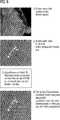
Eine zentrale Idee dieser ersten Ausführungsform der Erfindung ist es, MIP-I und MIP-D zu fusionieren, um ein Bild zu generieren, welches sowohl die maximale Intensität/Dichte als auch eine Vorstellung von der relativen Entfernung von Objekten, insbesondere von Kalzifizierungen, liefert. Dieses Konzept ist schematisch in
Für die Kodierung kann z.B. ein HSV-Farbraum verwendet werden. Beim HSV-Farbraum werden mit Hilfe des Farbwertes (engl. hue) der Farbsättigung (saturation) und des Helligkeitswerts bzw. Hellwerts oder Dunkelstufe (value) die Raumpunkte definiert. Statt eines HSV-Farbraums könnte auch ein HSL-Farbraum, ein HSB-Farbraum und ein HSI-Farbraum verwendet werden. Im Rahmen des Ausführungsbeispiels wird die Farbinformation verwendet, um die Tiefeninformation zu kodieren. Idealerweise wird der Farbbereich beschränkt, um nicht den Radiologen durch ein zu buntes Erscheinungsbild zu sehr abzulenken.For coding, e.g. a HSV color space can be used. In the HSV color space, the color points (hue) of the saturation (saturation) and the brightness value or light value or dark level (value) are used to define the spatial points. Instead of an HSV color space, an HSL color space, an HSB color space and an HSI color space could also be used. In the exemplary embodiment, the color information is used to encode the depth information. Ideally, the color range is limited in order not to distract the radiologist too much by a too colorful appearance too much.
Es ist möglich, dass ein selektives An- und Abschalten der Farbinformation, eventuell bereichsabhängig, vorgesehen ist.It is possible that a selective switching on and off of the color information, possibly area-dependent, is provided.
Die Fusionierung der beiden Informationen MIP-I und MIP-D, üblicherweise auf einen Wertebereich von 0 bis 1 normiert, in ein Bild kann wie folgt durchgeführt werden.
- 1. In dem HSV-Farbraum wird der „V“-Kanal mit MIP-I belegt. D.h., dass der maximale Dichtewert (MIP-I) durch die Helligkeit des Bildes dargestellt wird.
- 2. In dem HSV-Farbraum wird der „H“-Kanal auf Werte gesetzt, die durch eine von der Variable MIP-D abhängige Funktion definiert sind. Ein mögliches Beispiel für diese Funktion ist
H(MIP-D(u,v)) = (MIP-D(u,v))0,5. - 3. Im HSV-Farbraum kann der „S“-Kanal auf einen konstanten Wert (z.B. 0,5) gesetzt werden. Dabei ist zu bemerken, dass es auch möglich wäre, MIP-I und/oder MIP-D zu verwenden, um den „S“-Wert, d.h. die Saturation des Bildes festzulegen.
- 1. In the HSV color space, the "V" channel is mapped to MIP-I. That is, the maximum density value (MIP-I) is represented by the brightness of the image.
- 2. In the HSV color space, the "H" channel is set to values defined by a function dependent on the variable MIP-D. A possible example of this feature is
H (MIP-D (u, v)) = (MIP-D (u, v))0.5 . - 3. In the HSV color space, the "S" channel can be set to a constant value (eg 0.5). It should be noted that it would also be possible to use MIP-I and / or MIP-D to set the "S" value, ie the saturation of the image.
Im Folgenden wird ein möglicher Workflow vorgestellt, den der Radiologe in der Praxis durchführen kann. Die farbkodierte Tiefeninformation liefert zusätzliche Informationen für den Radiologen. Dieser Workflow könnte wie folgt gestaltet sein:
- 1. Der Radiologe schaut die Grauwerte des synthetischen Mammogramms zuerst an.
- 2. Durch Aktivierung mittels einer Bedienschnittstelle wird das farbkodierte synthetische Mammogramm dargestellt. Der Radiologe kann somit besser die räumliche Verteilung der Kalzifizierungen und ähnlicher Strukturen bestimmen.
- 3. Der Radiologe analysiert die rekonstruierten Tomosyntheseschnitte. Das vorher erworbene Wissen durch die Betrachtung des synthetischen Mammogramms und der farbkodierten Tiefeninformation helfen ihm, sich auf interessierte Strukturen zu fokussieren.
- 1. The radiologist first looks at the gray levels of the synthetic mammogram.
- 2. Activation by means of a user interface displays the color-coded synthetic mammogram. The radiologist can thus better determine the spatial distribution of the calcifications and similar structures.
- 3. The radiologist analyzes the reconstructed tomosynthesis sections. The previously acquired knowledge through the consideration of the synthetic mammogram and the color-coded depth information help him to focus on interested structures.
Es ist zu bemerken, dass das farbkodierte synthetische Mammogramm zu einem aus Grauwerten bestehenden Mammogramm konvertiert kann, indem die „H“- und „S“-Kanäle auf 0 gesetzt werden. So könnten beispielsweise, um Speicherplatz zu sparen, nur die farbkodierten synthetischen Mammogramme gespeichert werden.It should be noted that the color-coded synthetic mammogram can be converted to a gray scale mammogram by setting the "H" and "S" channels to zero. For example, to save storage space, only the color-coded synthetic mammograms could be stored.
Ein weiterer Vorteil dieser Vorgehensweise ist, dass Farbmonitore, die mit Mammographiebildern verwendet werden können, kommerziell vertrieben werden. Beispielsweise der EizoRadiForce RX840-MG Monitor ist ein Farbmonitor, der FDA510(k) Zulassung für Mammographie besitzt.Another advantage of this approach is that color monitors that can be used with mammographic images are sold commercially. For example, the EizoRadiForce RX840-MG Monitor is a color monitor that has FDA510 (k) approval for mammography.
Im Folgenden wird ein zweites Ausführungsbeispiel vorgestellt. Die prinzipielle Vorgehensweise einer ersten Variante ist in
Für eine genauere Beschreibung dieses Ausführungsbeispiels werden die Variablen MIP-I(u,v) und MIP-W(u,v) eingeführt. Dabei ist die Variable MIP-I(u,v) wie in dem ersten Ausführungsbeipiel definiert. Die Variable MIP-W(u,v) ist wie folgt definiert.For a more detailed description of this embodiment, the variables MIP-I (u, v) and MIP-W (u, v) are introduced. Here, the variable MIP-I (u, v) is defined as in the first embodiment. The variable MIP-W (u, v) is defined as follows.
MIP-W(u,v):R2 → R3 (W = Welt): Diese Variable kodiert die Position des Maximums entlang dem Strahl in einem Weltkoordinatensystem bzw. einem raumfesten Koordinatensystem. Der Ursprung des Koordinatensystems kann z.B. im Zentrum des Detektors liegen. Da MIP-W sich auf drei Dimensionen beziehende Einträge hat, kann ein euklidischer Abstand berechnet werden.MIP-W (u, v): R2 → R3 (W = world): This variable encodes the position of the maximum along the beam in a world coordinate system or a space-fixed coordinate system. For example, the origin of the coordinate system may be in the center of the detector. Since MIP-W has entries related to three dimensions, an Euclidean distance can be calculated.
Mit diesen generierten Variablen MIP-I und MIP-W wird ein Workflow vorgeschlagen, der eine Berechnung des tatsächlichen dreidimensionalen Abstands erlaubt.With these generated variables MIP-I and MIP-W, a workflow is proposed that allows a calculation of the actual three-dimensional distance.
Das Dichte- bzw. Intensitätsbild MIP-I (möglicherweise ergänzt durch weitere Bildbearbeitung oder durch Verbindung mit anderen Bildinhalten, wie z.B. DRRs etc.) wird für den Radiologen auf einer Anzeige dargestellt.The MIP-I density image (possibly supplemented by further image processing or by association with other image contents such as DRRs, etc.) is displayed to the radiologist on a display.
Es sind nun zwei unterschiedliche Szenarien denkbar:
- 1. Um eine Abstandsbestimmung zwischen zwei Punkten auf dem dargestellt Bild zu bestimmen, wird wie folgt vorgegangen: – Es wird auf zwei Punkte im Bild geklickt, beispielsweise auf zwei herausstehende Kalzifizierungen gemäß MIP-I. – Falls es eine starke Variation der Tiefenkoordinaten in der Nachbarschaft der Stelle gibt, die der Benutzer anklickt, ist es besonders wichtig, wo der Messpunkt gesetzt wird. In diesem Fall z.B. könnte der Punkt mit der höchsten Intensität (CALC in
6 ) in der Nachbarschaft ausgewählt werden. – Die euklidische Entfernung zwischen zwei ausgewählten Punkten wird mittels der MIP-W-Koordinaten berechnet und der tatsächliche dreidimensionale Abstand auf dem Bildschirm angezeigt. Zur besseren Nachvollziehbarkeit kann der Abstand in einen Abstand innerhalb der Ebene und einen Tiefenabstand aufgespalten und in dieser Form angezeigt werden.
- 1. To determine a distance determination between two points on the displayed image, proceed as follows: - Click on two points in the image, for example on two protruding calcifications according to MIP-I. - If there is a large variation in the depth coordinates in the neighborhood of the location the user clicks on, it is particularly important where the measurement point is set. In this case, for example, the highest intensity point (CALC in
6 ) are selected in the neighborhood. - The Euclidean distance between two selected points is calculated using the MIP-W coordinates and the actual three-dimensional distance is displayed on the screen. For better traceability, the distance can be split into a distance within the plane and a depth distance and displayed in this form.
Dies ist in
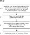
Eine zweite Variante der zweiten Ausführungsform betrifft die Vermessung eines Kalzifizierungsclusters, d.h. einer Ansammlung von Kalzifizierungen (
Es wird von Hand eine ROI (Region of Interest) um einen Kalzifizierungscluster in den dargestellten MIP/MIP/I gezogen (Schritt
Ein Algorithmus identifiziert die Kalzifizierungen in dem zu definierten Bereich, d.h. die Punkte mit der höchsten Intensität bezüglich der MIP-I-Variable (Schritt
Der Algorithmus sammelt dann alle dreidimensionalen Weltkoordinateninformationen für alle detektierten Kalzifizierungen in dem Cluster und generiert eine flexible dreidimensionale begrenzende Box, welche die dreidimensionale Punktwolke beinhaltet (Schritt
Statistische Informationen (Größe, Form) der Kalzifizierungen innerhalb dieser Box werden berechnet und auf dem Schirm an- gezeigt (Schritt
Da die Messpunkte und die beschränkende Box in Weltkoordinaten sind, können leicht zusätzlich die rekonstruierten Tomosyntheseschnitte eingeblendet werden, um so eine bessere Vergleichbarkeit zu gewährleisten.Since the measuring points and the limiting box are in world coordinates, the reconstructed tomosynthesis sections can easily be superimposed in order to ensure better comparability.
Insgesamt wird also mit der Erfindung ein bildgebendes Tomosynthesesystem, insbesondere ein Mammographiesystem, vorgeschlagen, welches mit einem Computersystem ausgestattet ist, welches Röntgenprojektionen eines Untersuchungsobjektes aus mehreren Projektionswinkeln erstellt, einen Stapel tomosynthetischer Schnittbilder rekonstruiert, aus diesen mindestens ein Übersichtsbild von Dichtewerten eines Untersuchungsobjektes erzeugt, charakteristische Dichtewerte im Stapel an mindestens einer Ebenenposition auswählt, die geometrische Höhe, vorzugsweise senkrecht zur Schnittbildebene, des mindestens einen ausgewählten charakteristischen Dichtewertes bestimmt und das Übersichtsbild mit einem, zur geometrischen Höhe des mindestens einen charakteristischen Dichtewertes korrelierenden, Farbwert darstellt, indem die pixelweise kombinierten Dichte- und Höhenwerte an den Eingang einer Anzeigeeinheit ausgegeben werden.Overall, therefore, the invention proposes an imaging tomosynthesis system, in particular a mammography system, which is equipped with a computer system that generates X-ray projections of an examination object from several projection angles, reconstructs a stack of tomosynthetic sectional images, generates at least one overview image of density values of an examination subject, characteristic Selects density values in the stack at at least one plane position, determines the geometric height, preferably perpendicular to the slice image plane, of the at least one selected characteristic density value and displays the overview image with a color value that correlates to the geometric height of the at least one characteristic density value by the pixel-by-pixel combined density value. and altitude values are output to the input of a display unit.
Obwohl die Erfindung im Detail durch die bevorzugten Ausführungsbeispiele näher illustriert und beschrieben wurde, so ist die Erfindung nicht durch die offenbarten Beispiele eingeschränkt und andere Variationen können vom Fachmann hieraus abgeleitet werden, ohne den Schutzumfang der Erfindung zu verlassen. Insbesondere beschränkt sich die Erfindung nicht auf die nachfolgend angegebenen Merkmalskombinationen, sondern es können auch für den Fachmann offensichtlich ausführbare andere Kombinationen und Teilkombination aus den offenbarten Merkmalen gebildet werden.While the invention has been further illustrated and described in detail by the preferred embodiments, the invention is not limited by the disclosed examples, and other variations can be derived therefrom by those skilled in the art without departing from the scope of the invention. In particular, the invention is not limited to the following combinations of features, but it can also be formed for the skilled person obviously executable other combinations and sub-combination of the disclosed features.
ZITATE ENTHALTEN IN DER BESCHREIBUNG QUOTES INCLUDE IN THE DESCRIPTION
Diese Liste der vom Anmelder aufgeführten Dokumente wurde automatisiert erzeugt und ist ausschließlich zur besseren Information des Lesers aufgenommen. Die Liste ist nicht Bestandteil der deutschen Patent- bzw. Gebrauchsmusteranmeldung. Das DPMA übernimmt keinerlei Haftung für etwaige Fehler oder Auslassungen.This list of the documents listed by the applicant has been generated automatically and is included solely for the better information of the reader. The list is not part of the German patent or utility model application. The DPMA assumes no liability for any errors or omissions.
Zitierte PatentliteraturCited patent literature
- US 2013/0064440 A1[0007]US 2013/0064440 A1[0007]
Claims (14)
Translated fromGermanPriority Applications (3)
| Application Number | Priority Date | Filing Date | Title |
|---|---|---|---|
| DE102015204957.4ADE102015204957A1 (en) | 2014-03-27 | 2015-03-19 | Imaging tomosynthesis system, in particular mammography system |
| US14/670,750US9401019B2 (en) | 2014-03-27 | 2015-03-27 | Imaging tomosynthesis system, in particular mammography system |
| CN201510140500.XACN104939850B (en) | 2014-03-27 | 2015-03-27 | Imaging fault synthesis system, particularly mammary gland angiography system |
Applications Claiming Priority (3)
| Application Number | Priority Date | Filing Date | Title |
|---|---|---|---|
| DE102014205756.6 | 2014-03-27 | ||
| DE102014205756 | 2014-03-27 | ||
| DE102015204957.4ADE102015204957A1 (en) | 2014-03-27 | 2015-03-19 | Imaging tomosynthesis system, in particular mammography system |
Publications (1)
| Publication Number | Publication Date |
|---|---|
| DE102015204957A1true DE102015204957A1 (en) | 2015-10-01 |
Family
ID=54067136
Family Applications (1)
| Application Number | Title | Priority Date | Filing Date |
|---|---|---|---|
| DE102015204957.4APendingDE102015204957A1 (en) | 2014-03-27 | 2015-03-19 | Imaging tomosynthesis system, in particular mammography system |
Country Status (3)
| Country | Link |
|---|---|
| US (1) | US9401019B2 (en) |
| CN (1) | CN104939850B (en) |
| DE (1) | DE102015204957A1 (en) |
Cited By (2)
| Publication number | Priority date | Publication date | Assignee | Title |
|---|---|---|---|---|
| DE102016210093A1 (en)* | 2016-06-08 | 2017-12-14 | Siemens Healthcare Gmbh | Procedure for planning an investigation |
| DE102022003163A1 (en) | 2022-08-30 | 2024-02-29 | Ziehm Imaging Gmbh | Method for taking a large-area X-ray image |
Families Citing this family (18)
| Publication number | Priority date | Publication date | Assignee | Title |
|---|---|---|---|---|
| US11051771B2 (en) | 2014-06-17 | 2021-07-06 | Xintek, Inc. | Stationary intraoral tomosynthesis imaging systems, methods, and computer readable media for three dimensional dental imaging |
| KR102377626B1 (en)* | 2015-03-27 | 2022-03-24 | 주식회사바텍 | System of processing X-ray image and method of using the same |
| KR20180115725A (en) | 2016-02-08 | 2018-10-23 | 이마고 시스템즈, 인크. | System and method for visualization and characterization of objects in an image |
| JP6747852B2 (en)* | 2016-04-11 | 2020-08-26 | キヤノンメディカルシステムズ株式会社 | Medical image processing apparatus, medical information processing system, and medical information processing program |
| CN106067193B (en)* | 2016-06-06 | 2019-02-19 | 中国人民解放军信息工程大学 | A voxelization method for point cloud data and a voxel occlusion cropping method |
| CN107545551B (en)* | 2017-09-07 | 2018-11-16 | 广州华端科技有限公司 | The method for reconstructing and system of digital galactophore body layer composograph |
| US10679384B2 (en) | 2017-09-29 | 2020-06-09 | General Electric Company | Systems and methods for deep learning-based image reconstruction |
| US12004890B2 (en) | 2018-10-26 | 2024-06-11 | Surround Medical Systems, Inc. | Intraoral tomosynthesis X-ray imaging device, system, and method with interchangeable collimator |
| CN109584148A (en)* | 2018-11-27 | 2019-04-05 | 重庆爱奇艺智能科技有限公司 | A kind of method and apparatus handling two-dimentional interface in VR equipment |
| US11227418B2 (en)* | 2018-12-28 | 2022-01-18 | General Electric Company | Systems and methods for deep learning-based image reconstruction |
| CN109829896B (en)* | 2019-01-14 | 2023-04-07 | 中国科学院苏州生物医学工程技术研究所 | Automatic detection method for micro-calcification clusters of digital breast X-ray tomography image based on multi-domain features |
| EP3789963A1 (en)* | 2019-09-06 | 2021-03-10 | Koninklijke Philips N.V. | Confidence map for neural network based limited angle artifact reduction in cone beam ct |
| EP3798973A1 (en)* | 2019-09-30 | 2021-03-31 | Siemens Healthcare GmbH | Method for determining orthogonal slice image data records of a tomosynthesis capture |
| CN110796620B (en)* | 2019-10-29 | 2022-05-17 | 广州华端科技有限公司 | Interlayer artifact suppression method and device for breast tomographic reconstruction image |
| DE102020209706A1 (en)* | 2020-07-31 | 2022-02-03 | Siemens Healthcare Gmbh | Synthetic mammogram with reduced overlay of tissue changes |
| CN112055194B (en)* | 2020-09-17 | 2022-02-22 | 广东省科学院半导体研究所 | Three-dimensional space laser projection slice display device |
| CN114004738B (en)* | 2021-10-29 | 2025-07-25 | 上海联影医疗科技股份有限公司 | Method, apparatus, device and medium for processing digitized breast tomographic image |
| CN117314988B (en)* | 2023-11-29 | 2024-02-20 | 南京邮电大学 | DBT reconstruction method for multi-angle projection registration |
Citations (5)
| Publication number | Priority date | Publication date | Assignee | Title |
|---|---|---|---|---|
| US20030156747A1 (en)* | 2002-02-15 | 2003-08-21 | Siemens Aktiengesellschaft | Method for the presentation of projection images or tomograms from 3D volume data of an examination volume |
| US20090016483A1 (en)* | 2007-07-10 | 2009-01-15 | Kabushiki Kaisha Toshiba | X-ray apparatus, image processing display apparatus and computer program product |
| US20120176365A1 (en)* | 2011-01-07 | 2012-07-12 | General Electric Company | Method and system for measuring dimensions in volumetric ultrasound data |
| US20130064440A1 (en) | 2010-04-16 | 2013-03-14 | Koninklijke Philips Electronics N.V. | Image data reformatting |
| US20140037167A1 (en)* | 2011-04-20 | 2014-02-06 | Hitachi Medical Corporation | Image display device for medical applications, image display method for medical applications |
Family Cites Families (15)
| Publication number | Priority date | Publication date | Assignee | Title |
|---|---|---|---|---|
| JP2006505366A (en)* | 2002-11-07 | 2006-02-16 | コンフォーミス・インコーポレイテッド | Method of determining meniscus size and shape and devised treatment |
| CN1264062C (en)* | 2002-12-31 | 2006-07-12 | 清华大学 | Method of multi viewing angle x-ray stereo imaging and system |
| US6901132B2 (en)* | 2003-06-26 | 2005-05-31 | General Electric Company | System and method for scanning an object in tomosynthesis applications |
| US20050135555A1 (en)* | 2003-12-23 | 2005-06-23 | Claus Bernhard Erich H. | Method and system for simultaneously viewing rendered volumes |
| FR2902218A1 (en)* | 2006-06-07 | 2007-12-14 | Gen Electric | METHOD FOR PROCESSING TOMOSYNTHESIS IMAGES FOR DETECTION OF RADIOLOGICAL SIGNS |
| US8179396B2 (en)* | 2006-08-02 | 2012-05-15 | General Electric Company | System and methods for rule-based volume rendition and navigation |
| US8051386B2 (en)* | 2006-12-21 | 2011-11-01 | Sectra Ab | CAD-based navigation of views of medical image data stacks or volumes |
| JP5319180B2 (en)* | 2007-07-10 | 2013-10-16 | 株式会社東芝 | X-ray imaging apparatus, image processing apparatus, and image processing program |
| US8493437B2 (en)* | 2007-12-11 | 2013-07-23 | Raytheon Bbn Technologies Corp. | Methods and systems for marking stereo pairs of images |
| US8094896B2 (en)* | 2008-04-14 | 2012-01-10 | General Electric Company | Systems, methods and apparatus for detection of organ wall thickness and cross-section color-coding |
| US20120014578A1 (en)* | 2010-07-19 | 2012-01-19 | Qview Medical, Inc. | Computer Aided Detection Of Abnormalities In Volumetric Breast Ultrasound Scans And User Interface |
| FR2954556B1 (en) | 2009-12-22 | 2017-07-28 | Gen Electric | METHOD OF PROCESSING TOMOSYNTHESIS ACQUISITIONS TO OBTAIN REPRESENTATION OF THE CONTENT OF AN ORGAN |
| DE102010063810B4 (en)* | 2010-12-21 | 2019-06-06 | Siemens Healthcare Gmbh | An imaging method and apparatus for displaying decompressed views of a tissue area |
| DE102011076929A1 (en)* | 2011-06-03 | 2012-12-06 | Siemens Ag | Method and apparatus for displaying volume data for a study of density properties |
| DE102011076930A1 (en)* | 2011-06-03 | 2012-12-06 | Siemens Aktiengesellschaft | Method and device for adapting the representation of volume data of an object |
- 2015
- 2015-03-19DEDE102015204957.4Apatent/DE102015204957A1/enactivePending
- 2015-03-27CNCN201510140500.XApatent/CN104939850B/enactiveActive
- 2015-03-27USUS14/670,750patent/US9401019B2/enactiveActive
Patent Citations (5)
| Publication number | Priority date | Publication date | Assignee | Title |
|---|---|---|---|---|
| US20030156747A1 (en)* | 2002-02-15 | 2003-08-21 | Siemens Aktiengesellschaft | Method for the presentation of projection images or tomograms from 3D volume data of an examination volume |
| US20090016483A1 (en)* | 2007-07-10 | 2009-01-15 | Kabushiki Kaisha Toshiba | X-ray apparatus, image processing display apparatus and computer program product |
| US20130064440A1 (en) | 2010-04-16 | 2013-03-14 | Koninklijke Philips Electronics N.V. | Image data reformatting |
| US20120176365A1 (en)* | 2011-01-07 | 2012-07-12 | General Electric Company | Method and system for measuring dimensions in volumetric ultrasound data |
| US20140037167A1 (en)* | 2011-04-20 | 2014-02-06 | Hitachi Medical Corporation | Image display device for medical applications, image display method for medical applications |
Non-Patent Citations (4)
| Title |
|---|
| Online-Enzyklopädie "Wikipedia", Artikel zum Begriff "Color Space" vom 3.2.2014, [recherchiert am 15.5.2015].* |
| Online-Enzyklopädie "Wikipedia", Artikel zum Begriff "Local Maximum intensity projection" vom 6.9.2012, [recherchiert am 15.5.2015].* |
| Online-Enzyklopädie „Wikipedia", Artikel zum Begriff „Color Space" vom 3.2.2014, [recherchiert am 15.5.2015]. |
| Online-Enzyklopädie „Wikipedia", Artikel zum Begriff „Local Maximum intensity projection" vom 6.9.2012, [recherchiert am 15.5.2015]. |
Cited By (5)
| Publication number | Priority date | Publication date | Assignee | Title |
|---|---|---|---|---|
| DE102016210093A1 (en)* | 2016-06-08 | 2017-12-14 | Siemens Healthcare Gmbh | Procedure for planning an investigation |
| US10115485B2 (en) | 2016-06-08 | 2018-10-30 | Siemens Healthcare Gmbh | Method of planning an examination, method of positioning an examination instrument, tomosynthesis system and computer program product |
| DE102022003163A1 (en) | 2022-08-30 | 2024-02-29 | Ziehm Imaging Gmbh | Method for taking a large-area X-ray image |
| EP4389008A1 (en) | 2022-08-30 | 2024-06-26 | Ziehm Imaging GmbH | Method for taking a large-area x-ray image |
| DE102022003163B4 (en) | 2022-08-30 | 2025-03-20 | Ziehm Imaging Gmbh | Method for taking a large-area X-ray image |
Also Published As
| Publication number | Publication date |
|---|---|
| US20150279064A1 (en) | 2015-10-01 |
| CN104939850A (en) | 2015-09-30 |
| US9401019B2 (en) | 2016-07-26 |
| CN104939850B (en) | 2018-07-06 |
Similar Documents
| Publication | Publication Date | Title |
|---|---|---|
| DE102015204957A1 (en) | Imaging tomosynthesis system, in particular mammography system | |
| DE102011087127B4 (en) | Determination of acquisition parameters in a dual-energy tomosynthesis | |
| DE102011087337B4 (en) | A method of reconstructing a reconstruction data set containing two-dimensional virtual X-ray images | |
| DE102011003137A1 (en) | Imaging method with an improved representation of a tissue area | |
| DE102012207629B4 (en) | CT image reconstruction in the extended measuring field | |
| DE102011003135B4 (en) | An imaging method for rotating a tissue area | |
| DE102011075904A1 (en) | A method for providing an image data set with suppressed over-field artifacts and X-ray image capture device | |
| EP3332710B1 (en) | Characterisation of plaque | |
| DE10353882A1 (en) | Method and device for visualizing soft tissue volume | |
| DE102006003609A1 (en) | Computer-tomography system for scanning patient, has visual representation unit comprising addressing representation function for marking partial area of visual representation and representing partial area in high image resolution | |
| DE10347971B3 (en) | Method and device for determining the liquid type of a liquid accumulation in an object | |
| DE102007046514A1 (en) | Method for detecting and marking contrast medium in blood vessels of the lung using a CT examination and image evaluation unit of a CT system | |
| DE102016219887A1 (en) | Method and system for using measured data | |
| DE102015206630B4 (en) | Multispectral CT imaging | |
| DE102011076930A1 (en) | Method and device for adapting the representation of volume data of an object | |
| EP3797698B1 (en) | Method for generating a synthetic mammogram based on dual-energy tomosynthesis capture | |
| EP1843296A1 (en) | Method for reproducible creation of views of tomographic image data | |
| DE102011076929A1 (en) | Method and apparatus for displaying volume data for a study of density properties | |
| DE102011075917A1 (en) | A method of providing a 3D image data set with suppressed cross-over artifacts and computed tomography | |
| DE102011005161B4 (en) | Method, image data set reconstruction device, X-ray system and computer program for artifact correction | |
| DE102015210912A1 (en) | Reconstruction of a result image taking into account contour significance data | |
| DE102016217776A1 (en) | Simultaneous imaging of functional and morphological X-ray image data of a breast | |
| DE102022103692A1 (en) | SYSTEMS AND METHODS FOR IDENTIFICATION OF BIOPSY POSITION COORDINATES | |
| DE102009007680A1 (en) | Method and apparatus for interactive CT reconstruction | |
| DE102008045449A1 (en) | Method of making computed tomographic images of a patient with metallic parts |
Legal Events
| Date | Code | Title | Description |
|---|---|---|---|
| R012 | Request for examination validly filed | ||
| R016 | Response to examination communication | ||
| R081 | Change of applicant/patentee | Owner name:SIEMENS HEALTHCARE GMBH, DE Free format text:FORMER OWNER: SIEMENS AKTIENGESELLSCHAFT, 80333 MUENCHEN, DE | |
| R081 | Change of applicant/patentee | Owner name:SIEMENS HEALTHINEERS AG, DE Free format text:FORMER OWNER: SIEMENS HEALTHCARE GMBH, MUENCHEN, DE |