DE102015200943A1 - sensor module - Google Patents
sensor moduleDownload PDFInfo
- Publication number
- DE102015200943A1 DE102015200943A1DE102015200943.2ADE102015200943ADE102015200943A1DE 102015200943 A1DE102015200943 A1DE 102015200943A1DE 102015200943 ADE102015200943 ADE 102015200943ADE 102015200943 A1DE102015200943 A1DE 102015200943A1
- Authority
- DE
- Germany
- Prior art keywords
- support base
- sensor
- sensor module
- motor vehicle
- module
- Prior art date
- Legal status (The legal status is an assumption and is not a legal conclusion. Google has not performed a legal analysis and makes no representation as to the accuracy of the status listed.)
- Pending
Links
Images


Classifications
- H—ELECTRICITY
- H04—ELECTRIC COMMUNICATION TECHNIQUE
- H04N—PICTORIAL COMMUNICATION, e.g. TELEVISION
- H04N7/00—Television systems
- H04N7/18—Closed-circuit television [CCTV] systems, i.e. systems in which the video signal is not broadcast
- B—PERFORMING OPERATIONS; TRANSPORTING
- B60—VEHICLES IN GENERAL
- B60R—VEHICLES, VEHICLE FITTINGS, OR VEHICLE PARTS, NOT OTHERWISE PROVIDED FOR
- B60R11/00—Arrangements for holding or mounting articles, not otherwise provided for
- B60R11/04—Mounting of cameras operative during drive; Arrangement of controls thereof relative to the vehicle
- B—PERFORMING OPERATIONS; TRANSPORTING
- B60—VEHICLES IN GENERAL
- B60R—VEHICLES, VEHICLE FITTINGS, OR VEHICLE PARTS, NOT OTHERWISE PROVIDED FOR
- B60R19/00—Wheel guards; Radiator guards, e.g. grilles; Obstruction removers; Fittings damping bouncing force in collisions
- B60R19/02—Bumpers, i.e. impact receiving or absorbing members for protecting vehicles or fending off blows from other vehicles or objects
- B60R19/48—Bumpers, i.e. impact receiving or absorbing members for protecting vehicles or fending off blows from other vehicles or objects combined with, or convertible into, other devices or objects, e.g. bumpers combined with road brushes, bumpers convertible into beds
- B60R19/483—Bumpers, i.e. impact receiving or absorbing members for protecting vehicles or fending off blows from other vehicles or objects combined with, or convertible into, other devices or objects, e.g. bumpers combined with road brushes, bumpers convertible into beds with obstacle sensors of electric or electronic type
Landscapes
- Engineering & Computer Science (AREA)
- Mechanical Engineering (AREA)
- Multimedia (AREA)
- Signal Processing (AREA)
- Studio Devices (AREA)
Abstract
Translated fromGermanDescription
Translated fromGermanDie Erfindung betrifft ein Sensormodul für ein Fahrerassistenzsystem eines Kraftfahrzeuges, welches zur Erfassung von Informationen über das Umfeld des Kraftfahrzeuges ausgebildet ist und eine Trägerbasis sowie einen Sensor umfasst. Die Erfindung betrifft weiterhin ein Verfahren zur Herstellung eines entsprechenden Sensormoduls.The invention relates to a sensor module for a driver assistance system of a motor vehicle, which is designed to collect information about the environment of the motor vehicle and comprises a carrier base and a sensor. The invention further relates to a method for producing a corresponding sensor module.
Aktuell werden mehr und mehr Kraftfahrzeuge mit Sensoreinheiten ausgestattet, mit deren Hilfe Informationen über das Umfeld eines Kraftfahrzeuges erfasst werden. Jene Informationen werden dann nachfolgend als Datenbasis genutzt, um mit deren Hilfe bestimmte Funktionen durch ein Fahrerassistenzsystem zu realisieren, die einen Fahrer oder Fahrzeugführer bei der Fahrzeugführung unterstützen sollen. Entsprechende Fahrerassistenzsysteme arbeiten dabei umso genauer und/oder zuverlässiger, je genauer bzw. zuverlässiger die Sensoreinheiten sind, mit deren Hilfe die Datenbasis generiert wird.Currently, more and more motor vehicles are equipped with sensor units, with the help of information about the environment of a motor vehicle are detected. This information is then used as a database in order to realize with their help certain functions by a driver assistance system, which should assist a driver or driver in driving the vehicle. Corresponding driver assistance systems work all the more accurately and / or reliably, the more accurate or reliable the sensor units are, with the aid of which the database is generated.
Zudem bedingt der vermehrte Einsatz entsprechender Fahrerassistenzsysteme einen erhöhten Bedarf an entsprechenden Sensoreinheiten, sodass die Notwendigkeit besteht, größere Mengen oder Stückzahlen zu produzieren, was auch zu höheren Anforderungen an die Fertigung und die einzelnen Fertigungsprozessschritte führt. Dabei gilt es auch zu bedenken, dass ein typisches Fertigungsverfahren eine Vielzahl an Herstellungsprozessschritten umfasst, wobei jeder einzelne Prozessschritt zwangsläufig eine gewisse Ungenauigkeit mit sich bringt. Dabei wirken mitunter die Toleranzen mehrerer Herstellungsprozessschritte oder Fertigungsprozessschritte ungünstig zusammen, sodass das Herstellungsverfahren im ungünstigsten Fall als Ganzes eine relativ hohe Ungenauigkeit aufweist, obwohl die einzelnen Fertigungsprozessschritte jeweils recht genau sind, also eine recht geringe Toleranz aufweisen.In addition, the increased use of corresponding driver assistance systems requires an increased demand for corresponding sensor units, so that there is a need to produce larger quantities or quantities, which also leads to higher demands on the production and the individual manufacturing process steps. It should also be remembered that a typical manufacturing process includes a variety of manufacturing process steps, with each individual process step inevitably brings a degree of inaccuracy. Sometimes the tolerances of several manufacturing process steps or production process steps unfavorably cooperate, so that the manufacturing process in the worst case as a whole has a relatively high inaccuracy, although the individual manufacturing process steps are each quite accurate, so have a fairly low tolerance.
Ausgehend hiervon liegt der Erfindung die Aufgabe zugrunde, ein vorteilhaft ausgestaltetes Sensormodul sowie ein vorteilhaftes Verfahren zur Herstellung entsprechender Sensormodule anzugeben.Proceeding from this, the object of the invention is to specify an advantageously designed sensor module and an advantageous method for producing corresponding sensor modules.
Diese Aufgabe wird erfindungsgemäß gelöst durch ein Sensormodul mit den Merkmalen des Anspruchs 1 sowie durch ein Verfahren mit den Merkmalen des Anspruchs 13. Bevorzugte Weiterbildungen sind in den rückbezogenen Ansprüchen enthalten. Die im Hinblick auf das Sensormodul angeführten Vorteile und bevorzugten Ausgestaltungen sind sinngemäß auch auf das Verfahren übertragbar und umgekehrt.This object is achieved by a sensor module with the features of claim 1 and by a method having the features of claim 13. Preferred developments are contained in the dependent claims. The advantages and preferred embodiments cited with regard to the sensor module are analogous to the method and vice versa.
Ein entsprechendes Sensormodul ist dabei für ein Fahrerassistenzsystem eines Kraftfahrzeuges ausgelegt und dient zur Erfassung von Informationen über das Umfeld des Kraftfahrzeuges. Es umfasst eine Trägerbasis und einen Sensor oder ein Sensorsystem, wobei der Sensor bzw. das Sensorsystem unmittelbar an der Trägerbasis befestigt ist. Die unmittelbare Befestigung an der Trägerbasis hat dabei je nach Ausführungsvariante des Sensormoduls zum Teil unterschiedliche Vorteile, wobei sich einige Vorteile auf das Sensormodul selbst auswirken, wohingegen andere Vorteile günstig für das Herstellungsverfahren zur Herstellung des Sensormoduls sind.A corresponding sensor module is designed for a driver assistance system of a motor vehicle and serves for detecting information about the environment of the motor vehicle. It comprises a carrier base and a sensor or a sensor system, wherein the sensor or the sensor system is fastened directly to the carrier base. Depending on the design variant of the sensor module, the direct attachment to the carrier base sometimes has different advantages, with some advantages having an effect on the sensor module itself, whereas other advantages are favorable for the manufacturing method for producing the sensor module.
Ersteres ist beispielsweise der Fall, wenn der Sensor relativ viel Abwärme generiert und die Trägerbasis aus Metall gefertigt ist, da in diesem Fall die Trägerbasis quasi als passiver Kühler genutzt werden kann, um die Abwärme des Sensors vom Sensor weg zu befördern. Vorteilhaft für das Herstellungsverfahren ist die unmittelbare Befestigung an der Trägerbasis hingegen, wenn das Sensormodul zusätzlich zum Sensor weitere Baugruppen umfasst, die allesamt relativ zueinander ausgerichtet werden müssen, um eine hohe Präzision und/oder Zuverlässigkeit des Sensormoduls zu erreichen. In diesem Fall lässt sich dann die Trägerbasis als Bezugssystem bei der Ausrichtung all dieser Baugruppen nutzen, was zu einer günstigen Toleranzkette beim Herstellungsverfahren führt. Hierdurch lässt sich also vermeiden, dass die Ungenauigkeiten der einzelnen Fertigungsprozessschritte ungünstig zusammenwirken und dementsprechend lässt sich für das gesamte Herstellungsverfahren zur Herstellung des Sensormoduls eine relativ hohe Genauigkeit und geringe Toleranz realisieren.The former is the case, for example, when the sensor generates a relatively large amount of waste heat and the support base is made of metal, since in this case the support base can be used as a passive cooler so as to move the sensor's waste heat away from the sensor. On the other hand, the direct attachment to the carrier base is advantageous for the production method if the sensor module comprises additional assemblies in addition to the sensor, all of which must be aligned relative to one another in order to achieve high precision and / or reliability of the sensor module. In this case, then the carrier base can be used as a reference system in the alignment of all these assemblies, resulting in a favorable tolerance chain in the manufacturing process. As a result, it is possible to prevent the inaccuracies in the individual production process steps from interacting unfavorably, and accordingly, relatively high accuracy and low tolerance can be achieved for the entire production process for producing the sensor module.
Je nach Ausführungsvariante ist das Sensormodul hierbei vorzugsweise als Radarvorrichtung, als Lidarvorrichtung oder als Umfeldkamera ausgebildet, wobei die Umfeldkamera entweder als einfache Monokamera mit einem Bildsensor oder aber als so genannte Stereokamera mit zwei Bildsensoren ausgestaltet ist. Das entsprechende Sensormodul wird dann im Rahmen der Herstellung des Kraftfahrzeuges oder im Rahmen einer Nachrüstung am oder im Kraftfahrzeug befestigt und zum Beispiel im Bereich des Kühlergrills, der Windschutzscheibe, einer Seitenscheibe, der Heckscheibe, der Motorhaube oder des Fahrzeugdaches positioniert. Typisch ist hierbei insbesondere eine Positionierung hinter einer Blende im Kühlergrill oder hinter der Windschutzscheibe.Depending on the embodiment variant, the sensor module here is preferably designed as a radar device, as a lidar device or as an environment camera, wherein the surrounding camera is configured either as a simple monocamera with an image sensor or as a so-called stereo camera with two image sensors. The corresponding sensor module is then attached as part of the production of the motor vehicle or as part of a retrofit on or in the motor vehicle and positioned, for example in the area of the grille, the windshield, a side window, the rear window, the hood or the vehicle roof. A typical feature here is a positioning behind a panel in the radiator grille or behind the windshield.
Erfolgt die Befestigung an einer Glasscheibe des Kraftfahrzeuges oder ist die Befestigung an einer solchen vorgesehen, so ist es je nach Ausgestaltung des Sensormoduls vorteilhaft, eine mittelbare Befestigung vorzusehen und eine Art Puffer, auch Bracket genannt, zwischen der Glasscheibe und den Sensormodul zu positionieren, zum Beispiel um die mechanische Belastung der Glasscheibe gering zu halten, um also insbesondere zu vermeiden, dass die Glasscheibe infolge von Temperaturveränderungen kritisch unter Spannung gesetzt wird. Der Puffer oder das Bracket ist hierzu typischerweise aus einem ausreichend flexiblen Material, wie einem Kunststoff, und/oder durch eine ausreichend flexibel gestalteten Körper gegeben. Die Befestigung des Sensormoduls erfolgt dann bevorzugt durch eine Befestigung der Trägerbasis am Puffer oder am Bracket, wobei die Befestigung weiter bevorzugt durch teilelastische Bauteilausprägungen oder Elemente wie Blattfedern lösbar ausgestaltet ist. Hierdurch ist der Einbau des Sensormoduls erleichtert und zudem erlaubt eine derartige Ausgestaltung der Befestigung einen einfachen Austausch im Rahmen einer Reparatur oder einen einfachen Ausbau im Zuge einer Fahrzeugverwertung.If attachment to a glass pane of the motor vehicle or attachment to such is provided, it is advantageous depending on the configuration of the sensor module to provide an indirect attachment and a kind of buffer, also called bracket, between the glass and the Position sensor module, for example, to keep the mechanical stress of the glass pane low, so in particular to avoid that the glass sheet is set as a result of temperature changes under critical tension. The buffer or the bracket is this typically made of a sufficiently flexible material, such as a plastic, and / or given by a sufficiently flexible body. The attachment of the sensor module is then preferably carried out by attachment of the support base on the buffer or on the bracket, wherein the attachment is further preferably designed releasable by partially elastic component characteristics or elements such as leaf springs. As a result, the installation of the sensor module is facilitated and also allows such a configuration of the attachment easy replacement as part of a repair or a simple removal in the course of vehicle utilization.
Der Puffer oder das Bracket selbst ist beispielsweise an der Glasscheibe angeklebt, durch eine Hinterspritzung ausgebildet oder aus der Glasscheibe ausgeformt. Da der Puffer bzw. das Bracket typischerweise zunächst an der Glasscheibe befestigt wird und nachfolgend das Sensormodul am Puffer, ist der Puffer als mechanische toleranzbehaftete Schnittstelle zum Sensormodul anzusehen, die noch bei der Ausgestaltung des Sensormoduls mit berücksichtigt werden muss. Auf die Genauigkeit der Ausrichtung des Puffers oder Brackest relativ zu Glasscheibe hingegen hat die Ausgestaltung des Sensormoduls und/oder der Herstellungsprozess zur Herstellung des Sensormoduls keinen Einfluss.The buffer or the bracket itself, for example, adhered to the glass, formed by a back injection or formed from the glass. Since the buffer or the bracket is typically first attached to the glass and then the sensor module at the buffer, the buffer is to be regarded as a mechanical interface with tolerance to the sensor module, which still has to be taken into account in the design of the sensor module. On the other hand, the design of the sensor module and / or the manufacturing process for the production of the sensor module has no influence on the accuracy of the orientation of the buffer or Brackest relative to the glass pane.
Insbesondere auch um den technischen Aufwand sowie die Herstellungskosten zu verringern, ist es weiter bevorzugt, das Sensormodul derart zu gestalten, dass die Trägerbasis durch Entformung aus einem plattenförmigen Körper hergestellt ist. Nach dem derzeitigen Stand der Technik hingegen werden derartige Bauteile oder Baugruppen mithilfe von Guss- oder Spritzgussverfahren hergestellt, was in der Regel aufwändige und kostenintensive Nachbearbeitungen, beispielsweise durch Bohren oder Fräsen, notwendig macht. Um auf entsprechende Nachbearbeitungen verzichten zu können, erfolgt die Herstellung der Trägerbasis erfindungsgemäß durch eine Entformung eines plattenförmigen Körpers und insbesondere mithilfe eines Stanz-Biegeverfahrens, so dass in diesem Fall die Trägerbasis als Stanzbiegeblech ausgebildet ist. Als Grundwerkstoff kommen dabei beispielsweise Metall, Kunststoff oder ein Verbundwerkstoff zum Einsatz.In particular, in order to reduce the technical complexity as well as the production costs, it is further preferred to design the sensor module such that the carrier base is produced by removal from a plate-shaped body. In the current state of the art, however, such components or assemblies are produced by means of casting or injection molding, which usually makes complicated and costly rework, for example by drilling or milling, necessary. In order to be able to dispense with corresponding reworking, the carrier base is produced according to the invention by a demolding of a plate-shaped body and in particular by means of a stamped-bending process, so that in this case the support base is formed as a stamped sheet metal. The base material used here, for example, metal, plastic or a composite material.
Ist bei der Fertigung der Trägerbasis ein Stanzprozessschritt vorgesehen, so ist es darüber hinaus je nach Ausgestaltungvariante des Sensormoduls zudem vorteilhaft, im Rahmen dieses Verfahrensschritts Strukturen, beispielsweise in Form von Dreieckprismen, an der Trägerbasis auszubilden oder in die Trägerbasis einzuprägen. Auf diese Weise lässt sich dann im Rahmen dieses Verfahrensschrittes zusätzlich eine Struktur mit günstigen Streueigenschaften realisieren, die beispielsweise als eine Art Streulichtblende im Falle einer Umfeldkamera genutzt werden kann.If a stamping process step is provided during the production of the support base, it is furthermore advantageous, depending on the design variant of the sensor module, to form structures, for example in the form of triangular prisms, on the support base or to impress them in the support base in the context of this method step. In this way, in the context of this process step, a structure with favorable scattering properties can additionally be realized, which can be used, for example, as a type of scattered light diaphragm in the case of an environment camera.
Wie zuvor bereits angedeutet wird bei der Herstellung des Sensormoduls die Trägerbasis bevorzugt als Bezugssystem bei der Ausrichtung diverser Baugruppen relativ zueinander genutzt. Zweckdienlicherweise sind dabei bei einem derart gefertigten Sensormodul zumindest diejenigen Modulbaugruppen relativ zur Trägerbasis und insbesondere relativ zu einer Kraftfahrzeugschnittstelle an der Trägerbasis ausgerichtet, die unmittelbar an der Trägerbasis befestigt sind und deren Ausrichtung relativ zueinander die Genauigkeit des Sensormoduls mitbestimmt. Da eine entsprechende Ausrichtung typischerweise mit einem durchaus hohen Aufwand verbunden ist, sind weiter bevorzugt nur diese Modulbaugruppen entsprechend aufwändig ausgerichtet, wohingegen bei anderen Baugruppen oder Bauteilen eine solche Ausrichtung nicht erfolgt.As already indicated above, in the production of the sensor module, the carrier base is preferably used as a reference system in the alignment of various assemblies relative to each other. Conveniently, in the case of a sensor module produced in this way, at least those module assemblies are aligned relative to the carrier base and in particular relative to a motor vehicle interface on the carrier base, which are fastened directly to the carrier base and whose orientation relative to one another determines the accuracy of the sensor module. Since a corresponding alignment is typically associated with a very high outlay, more preferably, only these module assemblies are correspondingly complex aligned, whereas in other assemblies or components such alignment does not take place.
Weiter umfasst der Sensor oder das Sensorsystem je nach Ausführung des Sensormoduls unterschiedliche Baugruppen und Komponenten und dementsprechend ist die Trägerbasis je nach Ausführung des Sensormoduls an verschiedene Baugruppen angepasst. Bildet das Sensormodul beispielsweise ein Lidarsystem aus, so umfasst der Sensor oder das Sensorsystem einen Sender, typischerweise mit zumindest einer Leuchtdiode oder einem Halbleiterlaser, sowie einen Empfänger, wobei für den Sender und den Empfänger eine gemeinsame Optik gegeben sein kann oder aber zwei getrennte Optiken für getrennte Wegstrecken für das ausgesendete und das empfangene Licht. Ist das Sensormodul hingegen als Radarsystem ausgestaltet, so umfasst das Sensorsystem Antennenstrukturen für das Aussenden und Empfangen von Radiowellen sowie Baugruppen zur Generierung und Auswertung elektromagnetischer Wechselfelder.Further, depending on the design of the sensor module, the sensor or the sensor system comprises different assemblies and components, and accordingly the carrier base is adapted to different assemblies depending on the design of the sensor module. If the sensor module forms, for example, a lidar system, then the sensor or the sensor system comprises a transmitter, typically with at least one light-emitting diode or a semiconductor laser, as well as a receiver, whereby a common optical system can be provided for the transmitter and the receiver or two separate optics for separate paths for the emitted and the received light. On the other hand, if the sensor module is designed as a radar system, the sensor system comprises antenna structures for transmitting and receiving radio waves as well as assemblies for generating and evaluating electromagnetic alternating fields.
Zweckmäßig ist darüber hinaus eine Ausgestaltung des Sensormoduls als Umfeldkamera, insbesondere auch, da entsprechende Umfeldkameras im Kraftfahrzeugbereich sehr verbreitet sind. In diesem Fall umfasst das Sensorsystem typischerweise zumindest einen optischen Sensor oder Bildsensor, zumindest eine Optik, bevorzugt ein einfaches Objektiv, sowie den zumindest einen optischen Sensor ergänzende Elektronikbaugruppen, mit Schnittstellen für einen Daten- und/oder Energieaustausch zwischen der Umfeldkamera, also dem Sensormodul, und dem Bordnetz des Kraftfahrzeuges. Die Befestigung des Bildsensors erfolgt dabei gemäß einer Ausführungsvariante so, dass der Bildsensor mit der Vorderseite an der Trägerbasis fixiert wird und im Betrieb dann quasi durch eine Materialaussparung oder ein Fenster an der Trägerbasis hindurch schaut.In addition, an embodiment of the sensor module as an environment camera is expedient, in particular also, since corresponding environment cameras are very widespread in the field of motor vehicles. In this case, the sensor system typically comprises at least one optical sensor or image sensor, at least one optic, preferably a simple objective, as well as electronic assemblies supplementing the at least one optical sensor, with interfaces for a data and / or energy exchange between the surrounding camera, ie the sensor module. and the electrical system of the motor vehicle. The attachment of the image sensor is carried out according to a variant such that the image sensor with the Front is fixed to the support base and then looks through the operation of quasi through a material recess or a window on the support base.
Wie bereits erwähnt umfasst das Sensormodul in vielen Fällen diverse elektrische und/oder elektronische Bausteine, wobei diese Bausteine typischerweise elektrisch leitend untereinander verbunden sind. Zumindest einige der hierfür notwendigen Leiterstrukturen sind dabei bevorzugt auf der Trägerbasis realisiert, z.B. indem Leiterbahnen aus Kupfer auf eine aus einem nicht leitfähigen Material hergestellte Trägerbasis aufgespritzt sind. Alternativ wird die aus einem leitfähigen Material hergestellte Trägerbasis mit einer Isolierung versehen, also beispielsweise mit einem isolierenden Lack beschichtet, und die entsprechenden Leiterstrukturen werden nachfolgend auf der Isolierung aufgebracht. Auf diese Weise lässt sich die Trägerbasis nicht nur als strukturgebende und/oder tragende Baueinheit nutzen, sondern darüber hinaus auch als eine Art Leiterplatte oder Leiterplatine, sodass beispielsweise auf eine zusätzliche Leiterplatte oder Leiterplatine verzichtet werden kann. Bevorzugt wird allerdings eine Ausgestaltung, bei der die auf der Trägerbasis realisierten Leiterstrukturen sonst übliche Kabelverbindungen ersetzen, über welche elektronische Module, wie beispielsweise ein Bildsensor und eine auf einer Platine realisierte Datenverarbeitungseinheit oder Auswerteeinheit, zwecks Energie- und/oder Datenaustausch miteinander verbunden sind.As already mentioned, the sensor module in many cases comprises various electrical and / or electronic components, these components typically being electrically conductively connected to one another. At least some of the conductor structures necessary for this purpose are preferably realized on the carrier base, e.g. by copper traces are sprayed onto a carrier base made of a non-conductive material. Alternatively, the carrier base made of a conductive material is provided with an insulation, that is, for example, coated with an insulating lacquer, and the corresponding conductor structures are subsequently applied to the insulation. In this way, the support base can be used not only as a structuring and / or supporting unit, but also as a kind of printed circuit board or printed circuit board, so that can be dispensed with, for example, an additional circuit board or printed circuit board. However, an embodiment is preferred in which the conductor structures realized on the carrier base replace otherwise conventional cable connections, via which electronic modules, such as an image sensor and a data processing unit or evaluation unit realized on a printed circuit board, are interconnected for the purpose of energy and / or data exchange.
In vorteilhafter Weiterbildung sind die Leiterstrukturen dabei durch Auflaminieren flexibler Leiterbahnen auf die Trägerbasis realisiert. Die Auflaminierung erfolgt dabei unmittelbar auf die Trägerbasis, zumindest sofern die Trägerbasis selbst nicht leitfähig ist oder aber das Laminat selbst ein isolierendes Leiterstrukturenbett aufweist, welches die Leiterstrukturen und die Trägerbasis gegeneinander isoliert.In an advantageous embodiment, the conductor structures are realized by laminating flexible conductor tracks on the carrier base. The lamination takes place directly on the support base, at least if the support base itself is not conductive or the laminate itself has an insulating conductor structure bed, which isolates the conductor structures and the support base against each other.
Dienen die Leiterstrukturen, wie bevorzugt, als Ersatz für Kabelverbindungen zwischen Elektronikmodulen oder Elektronikbausteinen, so sind die entsprechenden Elektronikmodule bzw. Elektronikbausteine zweckdienlicherweise unmittelbar an der Trägerbasis befestigt und an die Leiterstrukturen angebunden. Zusätzlich oder alternativ sind in einigen Fällen auch einzelne elektronische Bausteine oder elektrische Bausteine, wie beispielsweise Kondensatoren, an die Leiterstrukturen angebunden und dabei als einzelne Bausteine an der Trägerbasis befestigt. In jedem Fall aber dienen die auf der Trägerbasis aufgebrachten Leiterstrukturen, sofern vorgesehen und vorhanden, zur Anbindung des unmittelbar an der Trägerbasis befestigten Sensors, insbesondere eines Bildsensors, sodass über die Leiterstrukturen ein Datenaustausch erfolgen kann und/oder der Sensor mit elektrischer Energie versorgt wird.Serve the conductor structures, as preferred, as a replacement for cable connections between electronic modules or electronic components, the appropriate electronic modules or electronic components are conveniently attached directly to the support base and connected to the conductor structures. Additionally or alternatively, in some cases, individual electronic components or electrical components, such as capacitors, are connected to the conductor structures and attached as individual components to the support base. In any case, however, the conductor structures applied on the carrier base, if provided and present, serve for the connection of the sensor directly attached to the carrier base, in particular an image sensor, so that a data exchange can take place via the conductor structures and / or the sensor is supplied with electrical energy.
Bei der Herstellung der Leiterstrukturen und/oder der Bestückung mit elektrischen oder elektronischen Bausteinen wird zudem bevorzugt die Kraftfahrzeugschnittstelle als räumliches Bezugssystem genutzt, sodass auch diese Funktionselemente relativ zur Kraftfahrzeugschnittstelle an oder auf der Trägerbasis positioniert werden, so wie die meisten Baugruppen oder Komponenten des Sensormoduls. Hierzu wird bevorzugt ein Kraftfahrzeug-Dummy, Montage-Dummy oder auch kurz Dummy quasi als Werkbank genutzt, an welchem die Trägerbasis für die Fertigung oder für einzelne Fertigungsprozessschritte lösbar befestigt wird, sodass die Trägerbasis an der Kraftfahrzeugschnittstelle gehalten ist, und zwar insbesondere so, wie dies im verbauten Zustand der Trägerbasis oder vielmehr des vollständigen Sensormoduls in einem Kraftfahrzeug der Fall ist. Vorteilhafterweise erfolgen dabei alle Fertigungsprozessschritte, bei denen eine Relativausrichtung notwendig ist, nicht nur an einem solchen Dummy, sondern an demselben Dummy, d.h. dass die Fertigung eines Sensormoduls am einzigen Dummy vorgenommen wird.In the production of the conductor structures and / or the assembly of electrical or electronic components, the motor vehicle interface is also preferably used as a spatial reference system, so that these functional elements are positioned relative to the motor vehicle interface on or on the support base, as well as most assemblies or components of the sensor module. For this purpose, preferably a motor vehicle dummy, assembly dummy or short dummy is used quasi as a workbench, to which the support base for manufacturing or for individual manufacturing process steps is releasably attached, so that the support base is held on the motor vehicle interface, in particular as this is the case in the installed state of the carrier base or rather the complete sensor module in a motor vehicle. Advantageously, all manufacturing process steps in which a relative orientation is necessary, not only on such a dummy, but on the same dummy, i. that the production of a sensor module is performed on the single dummy.
Ist das Sensormodul als Umfeldkamera ausgebildet und der Sensor dementsprechend als Bildsensor, so weist das Sensormodul zudem typischerweise eine Optik auf. Dabei ist es günstig, die Optik ebenfalls unmittelbar an der Trägerbasis zu positionieren und zu fixieren, wobei die entsprechende Optik, so wie die meisten Module oder Modulbaugruppen, günstigerweise relativ zur Kraftfahrzeugschnittstelle ausgerichtet ist.If the sensor module is designed as an environment camera and the sensor accordingly as an image sensor, then the sensor module also typically has an optical system. It is advantageous to also position the optics directly to the support base and to fix, the corresponding optics, as well as most modules or module assemblies, is favorably aligned relative to the motor vehicle interface.
Im Zuge der Justage erfolgt hierbei zudem bevorzugt einerseits eine Ausrichtung zur Kraftfahrzeugschnittstelle und andererseits zum Bildsensor, um eine Fokussierung über das Sichtfeld zu erreichen. Dabei entspricht die klassischen x-y-Verschiebung der Optik einer Blickrichtungsausrichtung und die z-Verschiebung sowie die Drehung um die x- Achse sowie die y-Achse der eigentlichen Fokussierung. Eine Drehjustage um die Z-Achse hingegen ist nur bei nichtrotationssymmetrischen Optiken notwendig. In jedem Fall aber wird der Bildsensor während der Ausrichtung bevorzugt als Messaufnehmer genutzt und eine Objektstruktur mit Bezug auf die Kraftfahrzeugschnittstelle und somit auch auf den Montage-Dummy als Messtarget.In the course of the adjustment, an alignment to the motor vehicle interface and, on the other hand, to the image sensor preferably takes place on the one hand in order to achieve a focus over the field of view. The classical x-y shift of the optics corresponds to a viewing direction orientation and the z-shift as well as the rotation about the x-axis and the y-axis of the actual focusing. A rotational adjustment around the Z-axis, however, is only necessary for non-rotationally symmetrical optics. In any case, the image sensor is preferably used during the alignment as a sensor and an object structure with respect to the motor vehicle interface and thus also on the mounting dummy as a measurement target.
Die Optik weist dabei zumindest ein Abbildungselement auf und ist in der Regel aus mehreren Abbildungselementen aufgebaut, wobei je nach Anwendungszweck refraktive, reflektive und/oder difraktive Abbildungselemente zum Einsatz kommen. Die Befestigung erfolgt bevorzugt mithilfe eines unter UV-Licht aushärtenden Klebstoffes, der in einigen Fällen auch eine Sekundärhärtung zeigt, die durch Wärme, Ionenreaktion oder Feuchte ausgelöst wird. Die Ausrichtung erfolgt hierbei in sechs Freiheitsgraden, also drei Freiheitsgraden der Translation und drei Freiheitsgraden der Rotation, und während dieser Relativausrichtung ist die Trägerbasis, wie zuvor beschrieben, an der Kraftfahrzeugschnittstelle an einem Dummy gehalten.In this case, the optic has at least one imaging element and as a rule is made up of a plurality of imaging elements, refractive, reflective and / or diffractive imaging elements being used depending on the intended use. Fastening is preferably done using a UV-curable adhesive, which in some cases also exhibits secondary hardening, which is triggered by heat, ionic reaction or moisture. The alignment takes place here in six degrees of freedom, Thus, three degrees of freedom of translation and three degrees of freedom of rotation, and during this relative orientation, the support base, as described above, held on the motor vehicle interface on a dummy.
Unter anderem zum Schutz empfindlicher Baugruppen sowie zur Realisierung einer guten elektromagnetischen Verträglichkeit des Sensormoduls weist das Sensormodul des Weiteren eine gehäuseartige Aufnahme auf, welche in einer Ausführungsvariante durch Umformen oder Biegen des plattenförmigen Körpers und somit an der Trägerbasis ausgebildet ist. Die Aufnahme ist dabei beispielsweise ähnlich einem Bucheinband ausgestaltet, in welchem z.B. eine Leiterplatine oder eine ähnliche Elektronikbaugruppe einliegt und hierdurch von der gehäuseartigen Aufnahme geschützt und nach außen hin abgeschirmt wird. Zur Ausbildung einer solchen Aufnahme wird zweckdienlicherweise lediglich ein Abschnitt des plattenförmigen Körpers im Rahmen der Fertigung nach Art einer Lasche umgebogen.Among other things, for the protection of sensitive assemblies as well as for the realization of a good electromagnetic compatibility of the sensor module, the sensor module further comprises a housing-like receptacle, which is formed in a variant by forming or bending the plate-shaped body and thus on the support base. The receptacle is designed, for example, similar to a book cover, in which e.g. a printed circuit board or similar electronics module rests and is thus protected by the housing-like recording and shielded to the outside. To form such a receptacle, only a portion of the plate-shaped body is expediently bent over in the manner of a tab in the course of production.
In vorteilhafter Weiterbildung wird im Zuge des Umformens ein Gehäuse ausgebildet, welches nach allen Richtungen hin abgeschlossen ist und dementsprechend sechs Wandungen aufweist. Dabei liegen die meisten Wandungen aufgrund des Fertigungsprozesses zunächst lediglich lose aneinander an. Je nach Bedarf erfolgt jedoch in einem weiteren Fertigungsprozessschritt eine Befestigung der Wandungen aneinander und/oder eine Abdichtung des Gehäuses im Bereich der Schnittstellen zwischen den Wandungen, sodass hierdurch eine abgedichtete gehäuseartige Aufnahme ausgebildet ist. Diese Variante bedingt eine aufwendigere Fertigung und ist dementsprechend lediglich vorgesehen, wenn besonders empfindliche Elektronikbaugruppen zum Einsatz kommen, eine besonders hohe elektromagnetische Verträglichkeit gewährleistet werden muss und/oder wenn von besonderen Betriebsbedingungen ausgegangen wird. Besondere Betriebsbedingungen liegen dabei z.B. vor, wenn das Sensormodul unter klimatischen Bedingungen mit sehr hoher Luftfeuchtigkeit eingesetzt wird, die für einzelne Elektronikbaugruppen problematisch ist.In an advantageous embodiment, a housing is formed in the course of forming, which is completed in all directions and accordingly has six walls. Most of the walls initially lie loosely against each other due to the manufacturing process. Depending on requirements, however, a fastening of the walls to each other and / or a sealing of the housing takes place in the region of the interfaces between the walls in a further manufacturing process step, so that in this way a sealed housing-like receptacle is formed. This variant requires a more complex production and is accordingly provided only if particularly sensitive electronic assemblies are used, a particularly high electromagnetic compatibility must be ensured and / or if it is assumed that special operating conditions. Particular operating conditions are e.g. when the sensor module is used under climatic conditions with very high humidity, which is problematic for individual electronic assemblies.
Gemäß einer weiteren Ausführungsvariante bildet die Trägerbasis zusammen mit einem Verschlusselement, einer Art Deckel, ein Gehäuse aus. Dabei sind Ausbuchtungen an der Trägerbasis und/oder am Deckel vorgesehen, die an einer Umlaufenden leitenden Massebahn um die besonders empfindlichen Elektronikbaugruppen, z.B. einer Hauptplatine, eine Kontaktierung durch Verbinden von Deckel und Trägerbasis herstellen, so dass hierdurch die elektromagnetische Verträglichkeit erhöht ist und ein gezielter Verlauf für Elektrostatischen Entladungen vorgegeben ist.According to a further embodiment, the support base forms a housing together with a closure element, a kind of cover. In this case bulges are provided on the support base and / or on the lid, which are connected to a circulating conductive ground track around the particularly sensitive electronic assemblies, e.g. a motherboard, make a contact by connecting the cover and the carrier base, so that in this way the electromagnetic compatibility is increased and a specific course for electrostatic discharges is specified.
Durch die hier vorgestellte spezielle Ausgestaltung des Sensormoduls und die spezielle Gestaltung des Herstellungsverfahrens werden der Herstellungsaufwand und die Herstellungskosten reduziert. Dies ist nicht nur für den Hersteller von Vorteil, sondern auch für den Endkunden, da hierdurch entsprechende Sensormodule, die häufig Teil sicherheitsrelevanter Fahrerassistenzsysteme sind, nicht nur im sogenannten Luxussegment vermehrt zum Einsatz kommen, sondern auch in den sogenannten unteren Fahrzeugklassen, die die größte Verbreitung auf dem Kraftfahrzeugmarkt aufweisen.The presented here special design of the sensor module and the special design of the manufacturing process, the manufacturing cost and manufacturing costs are reduced. This is not only advantageous for the manufacturer, but also for the end customer, since corresponding sensor modules, which are often part of safety-relevant driver assistance systems, are increasingly used not only in the so-called luxury segment, but also in the so-called lower vehicle classes, which are the most widespread on the motor vehicle market.
Darüber hinaus ist mit dem Herstellungsverfahren eine günstigere Toleranzkette gegeben, sodass sich mit dem erfindungsgemäßen Herstellungsverfahren Sensormodule fertigen lassen, die im Mittel eine höhere Genauigkeit aufweisen. Die höhere Genauigkeit oder geringere Fertigungstoleranz für die Sensormodule wird dabei jedoch nicht durch eine Verringerung der Fertigungstoleranzen einzelner Fertigungsprozessschritte erreicht, was typischerweise mit einem erhöhten technischen und wirtschaftlichen Aufwand einhergeht, sondern quasi durch Entkoppelung der einzelnen Fertigungstoleranzen der einzelnen Fertigungsprozessschritte, sodass die einzelnen Fertigungstoleranzen der einzelnen Fertigungsprozessschritte weniger voneinander abhängig sind und sich somit auch weniger ungünstig gegenseitig beeinflussen können. Vereinfacht ausgedrückt könnte man sagen, dass die einzelnen Ungenauigkeiten unangetastet bleiben, sich aber quasi der sogenannte Größtfehler durch den veränderten Fertigungsprozess signifikant reduziert, was eine Fertigung der Sensormodule mit im Mittel größerer Genauigkeit erlaubt.In addition, a more favorable tolerance chain is given with the production method, so that sensor modules can be produced with the production method according to the invention, which on average have a higher accuracy. However, the higher accuracy or lower manufacturing tolerance for the sensor modules is not achieved by reducing the manufacturing tolerances of individual production process steps, which is typically associated with increased technical and economic effort, but quasi by decoupling the individual manufacturing tolerances of the individual manufacturing process steps, so that the individual manufacturing tolerances of the individual Manufacturing process steps are less dependent on each other and thus less unfavorable influence each other. In simple terms, one could say that the individual inaccuracies remain untouched, but that the so-called maximum error is reduced significantly by the changed production process, which makes it possible to manufacture the sensor modules with on average greater accuracy.
Hierzu wird zunächst ein Rohling gefertigt, indem ein Rohling für die Trägerbasis in einem Stanzprozess oder einem Stanzbiegeprozess hergestellt wird. Dieser besteht beispielsweise aus Metall oder Kunststoff und ist typischerweise plattenförmig ausgebildet. Dieser Rohling weist dabei bereits alle grundlegenden Formmerkmale auf, insbesondere alle Materialaussparungen, also z.B. Kabeldurchführungen, sodass der Rohling nicht mehr durch Bohren oder Fräsen nachbearbeitet werden muss.For this purpose, a blank is first manufactured by a blank for the support base is produced in a stamping process or a stamping bending process. This consists for example of metal or plastic and is typically plate-shaped. This blank already has all the basic shape features, in particular all material recesses, eg. Cable bushings, so that the blank no longer needs to be reworked by drilling or milling.
Der so entformte Rohling wird nachfolgend je nach Bedarf entgratet, gereinigt, lackiert und/oder beschichtet. Hierbei dient die Lackierung bzw. die Beschichtung je nach Anforderung zur Verbesserung der Streueigenschaften der späteren Trägerbasis, insbesondere wenn das Sensormodul als Umfeldkamera ausgebildet ist, und/oder zur Verbesserung der elektromagnetischen Verträglichkeit des späteren Sensormoduls.The blank thus removed is subsequently deburred, cleaned, painted and / or coated as required. Here, the coating or the coating serves as required to improve the scattering properties of the subsequent carrier base, in particular if the sensor module is designed as an environment camera, and / or to improve the electromagnetic compatibility of the subsequent sensor module.
Je nach Ausgestaltung des Sensormoduls erfolgt in einem nachfolgenden Fertigungsprozessschritt die Aufbringung von Leiterstrukturen, insbesondere Leiterbahnen, die typischerweise zur Übertragung von Signalen zwischen dem Sensor und einer Verarbeitungseinheit, typischerweise einer Art Hauptplatine, oder zwischen dem Sensor und einer Sensormodulschnittstelle hin zum Bordnetz des Kraftfahrzeuges, wobei die Sensormodulschnittstelle in der Regel nach Art eines Steckverbinders ausgestaltet ist. Die Leiterstrukturen werden dabei beispielsweise durch Aufdampfen, durch Lackieren oder durch Anregung eines Ausgangsmaterials durch Laserbestrahlung hergestellt. Alternativ wird eine Leiterplatine auf die Trägerbasis aufgelötet, aufgeklebt, aufgeschweißt oder aufgeschmolzen oder aber es werden flexible Leiterbahnen auf die Trägerbasis auflaminiert. In jedem Fall aber werden die geometrischen Merkmale der Trägerbasis vorteilhaft genutzt, um die Leiterstrukturen und infolgedessen dann auch die daran eingebundenen Elektronikkomponenten günstig zu positionieren, um auf diese Weise unter Anderem einen möglichst kompakten Aufbau des Sensormoduls zu realisieren.Depending on the configuration of the sensor module takes place in a subsequent Manufacturing process step, the application of conductor structures, in particular tracks, typically for transmitting signals between the sensor and a processing unit, typically a kind of motherboard, or between the sensor and a sensor module interface to the electrical system of the motor vehicle, the sensor module interface usually in the manner of a connector is designed. The conductor structures are produced, for example, by vapor deposition, by painting or by excitation of a starting material by laser irradiation. Alternatively, a printed circuit board is soldered, glued, welded or fused onto the carrier base or else flexible printed conductors are laminated onto the carrier base. In any case, however, the geometric features of the support base are advantageously used to position the conductor structures and consequently then the electronic components involved in low, in order to realize in this way, among other things, a very compact design of the sensor module.
Wie bereits erwähnt, dienen die Leiterstrukturen oder Leiterbahnen insbesondere dazu, den Sensor und eine Art Hauptplatine miteinander zu verbinden und aneinander anzukoppeln, wobei die Wegstrecke zwischen diesen beiden Baugruppen typischerweise 5 bis 50 mm beträgt. In einigen Fällen werden weitere elektrische oder elektronische Bausteine verbaut, die aus bestimmten Gründen in einer gewissen räumlichen Nähe zum Sensor oder zur Hauptplatine positioniert werden müssen. Derartige Bausteine werden dann bevorzugt direkt auf die Trägerbasis aufgelötet und/oder aufgeklebt und an die Leiterstrukturen angebunden. Als Bausteine kommen dabei Elemente, wie Widerstände, Kapazitäten oder Spulen zum Einsatz, aber auch komplexere Baugruppen, die beispielsweise zur Signalaufbereitung oder Vorverarbeitung dienen. All diese Bausteine werden bevorzugt mittels einer „Pick-and-Place-Maschine“ auf der Trägerbasis positioniert und durch Kleben, Löten, Schweißen oder Reflow-Löten fixiert.As already mentioned, the conductor structures or conductor tracks serve, in particular, to connect the sensor and a type of motherboard to one another and to couple them to one another, the distance between these two assemblies typically being 5 to 50 mm. In some cases, additional electrical or electronic components are installed, which for some reason have to be positioned in a certain spatial proximity to the sensor or to the motherboard. Such devices are then preferably soldered directly to the support base and / or glued and connected to the conductor structures. The components used include components such as resistors, capacitors or coils, but also more complex assemblies which serve, for example, for signal conditioning or preprocessing. All of these components are preferably positioned on the carrier base by means of a "pick-and-place machine" and fixed by gluing, soldering, welding or reflow soldering.
Da zumindest der Sensor in vielen Fällen durch eine empfindliche Halbleiterbaueinheit gegeben ist, erfolgen zumindest einige nachfolgende Fertigungsprozessschritte typischerweise unter Reinraumbedingungen oder zumindest vergleichbaren Bedingungen. Bei dem entsprechenden Halbleiterelement handelt es sich z.B. um einen Bildsensor, um ein Antennenstrukturmodul mit Hochfrequenzverarbeitung oder um eine Empfänger-Sender-Strecke zur Laufzeitenmessung in einem Lidar- oder Laser-Sensor. Insbesondere der Bildsensor ist dabei als „Bare-Die-Package“ (gesägter Wafer) gegeben und der entsprechende Sensor wird weiter bevorzugt im Bare-Chipverfahren auf die Trägerbasis aufgebracht.Since at least the sensor is in many cases given by a sensitive semiconductor component, at least some subsequent manufacturing process steps typically occur under clean-room conditions or at least comparable conditions. The corresponding semiconductor element is e.g. an image sensor, an antenna structure module with high-frequency processing, or a receiver-transmitter path for measuring the transit time in a lidar or laser sensor. In particular, the image sensor is given as a "bare-die package" (sawn wafer) and the corresponding sensor is further preferably applied to the carrier base in the bare-chip method.
Der Sensor und insbesondere der Bildsensor wird hierbei unmittelbar an der Trägerbasis befestigt. Unter unmittelbar wird dabei im Zusammenhang mit dieser Erfindung auch eine Befestigung verstanden, bei der zwischen dem Sensor und der Trägerbasis eine Befestigungsmasse, also insbesondere eine Klebemasse, eingebracht ist, sodass sich Sensor und Trägerbasis im Extremfall nicht direkt berühren. Eine Art Gehäuse für den Sensor, welches dann wiederum auf der Trägerbasis angebracht wird, ist hingegen nicht vorgesehen und genauso wenig wird der Sensor zunächst auf einer Leiterplatine befestigt, die dann wiederum auf der Trägerbasis fixiert wird. In einigen Fällen, wie zum Beispiel bei einem als Stereokamera ausgebildeten Sensormodul weist das Sensormodul mehr als einen Sensor auf. In diesem Fall werden dann alle Sensoren in entsprechender Weise an der Trägerbasis befestigt und jeweils relativ zur Kraftfahrzeugschnittstelle ausgerichtet.The sensor and in particular the image sensor is in this case attached directly to the carrier base. In the context of this invention, "direct" is also understood to mean an attachment in which a fastening compound, that is to say in particular an adhesive, is introduced between the sensor and the carrier base so that the sensor and carrier base do not touch each other directly in an extreme case. A kind of housing for the sensor, which in turn is then mounted on the support base, however, is not provided and neither is the sensor first mounted on a printed circuit board, which in turn is fixed on the support base. In some cases, such as with a sensor module configured as a stereo camera, the sensor module has more than one sensor. In this case, all sensors are then fastened to the carrier base in a corresponding manner and aligned in each case relative to the motor vehicle interface.
Erfolgt die Befestigung, wie bevorzugt, mithilfe einer Klebemasse, dann weist diese je nach Bedarf auch eine hohe Wärmeleitfähigkeit auf. Eine solche Klebemasse mit hoher Wärmeleitfähigkeit wird dabei eingesetzt, wenn der Sensor relativ viel Abwärme erzeugt, da in diesem Fall die Abwärme über die Klebemasse abgeführt werden kann. Zudem ist die Trägerbasis dann bevorzugt aus einem Material mit ebenfalls guter Wärmeleitfähigkeit, also insbesondere einem Metall, hergestellt, sodass die Trägerbasis zusätzlich als passiver Kühler dient.If the attachment, as preferred, using an adhesive, then this has, depending on the needs and also a high thermal conductivity. Such an adhesive with high thermal conductivity is used when the sensor generates relatively much waste heat, since in this case the waste heat can be dissipated via the adhesive. In addition, the carrier base is then preferably made of a material with likewise good thermal conductivity, ie in particular a metal, so that the carrier base additionally serves as a passive cooler.
Der Sensor wird dabei vor der endgültigen Fixierung an der Trägerbasis relativ zur Kraftfahrzeugschnittstelle ausgerichtet, wobei die Trägerbasis hierfür, gemäß dem zuvor beschriebenen Prinzip, an der Kraftfahrzeugschnittstelle an einem Dummy gehalten ist. Die Befestigung erfolgt hierbei bevorzugt mittels einer Klebemasse, die durch UV-Bestrahlung zum Aushärten gebracht wird, sodass der Sensor zunächst quasi schwimmend in der Klebemasse ausgerichtet werden kann und dann im ausgerichteten Zustand durch Bestrahlung der Klebemasse mit ultraviolettem Licht endgültig fixiert wird. Die Dicke oder Stärke der Klebemasse beträgt dabei bevorzugt etwa 10–100 µm, sodass durch die Klebemasse auch Rauigkeiten an der der Trägerbasis zugewandten Seite des Sensors ausgeglichen werden. Die Ausrichtung erfolgt zudem nicht nur durch Verschiebung in den drei Raumrichtungen, sondern darüber hinaus auch durch Rotation um drei orthogonale Rotationsachsen und als Referenz am Sensor, die quasi hin zur Kraftfahrzeugschnittstelle ausgerichtet wird, dient z.B. eine Kante des Sensors oder, im Falle eines Bildsensors, die Pixelstruktur.The sensor is thereby aligned relative to the motor vehicle interface before the final fixation on the carrier base, wherein the carrier base for this purpose, according to the principle described above, is held on the motor vehicle interface on a dummy. The attachment is in this case preferably by means of an adhesive which is brought to curing by UV irradiation, so that the sensor can be aligned virtually floating in the adhesive and then finally fixed in the aligned state by irradiation of the adhesive with ultraviolet light. The thickness or thickness of the adhesive is preferably about 10-100 μm, so that even roughnesses on the side of the sensor facing the support base are compensated by the adhesive. The alignment also takes place not only by displacement in the three spatial directions, but also by rotation about three orthogonal axes of rotation and as a reference to the sensor, which is virtually aligned towards the motor vehicle interface, is used, for example. an edge of the sensor or, in the case of an image sensor, the pixel structure.
Je nach Ausgestaltung des Sensors wird dieser in einem weiteren Prozessschritt, einem Bonding-Prozessschritt, mit der Leiterbahnstruktur, sofern vorhanden, verbunden, wobei hierfür bevorzugt dünne, elektrisch leitfähige Drähte aus beispielsweise Gold oder Aluminium verwendet werden. Die Anbindung oder das Bonding erfolgt dabei je nach Rahmenbedingungen, also u.a. je nach Materialauswahl, durch Kleben, Schweißen, Löten oder auch durch eine mechanische Verpressung. Dabei gilt es, die Drahtenden dauerhaft leitfähig zu fixieren und einen minimalen elektrischen Widerstand zu realisieren.Depending on the design of the sensor, it is connected in a further process step, a bonding process step, with the conductor track structure, if present, with preferably thin, electrically conductive wires made of, for example, gold or aluminum are used. Depending on the framework conditions, ie, depending on the choice of material, the bonding or bonding takes place by gluing, welding, soldering or by mechanical compression. It is important to fix the wire ends permanently conductive and to realize a minimum electrical resistance.
Ist das Sensormodul als Umfeldkamera ausgebildet, so wird typischerweise in einem weiteren Fertigungsprozessschritt eine Optik vor dem Sensor, hier dem Bildsensor, positioniert und an der Trägerbasis befestigt. Die Optik weist dabei zumindest ein Abbildungselement auf und ist in der Regel aus mehreren Abbildungselementen aufgebaut, wobei je nach Anwendungszweck refraktive, reflektive und/oder difraktive Abbildungselemente zum Einsatz kommen. Die Befestigung erfolgt wiederum bevorzugt mithilfe eines unter UV-Licht aushärtenden Klebstoffes. Die Ausrichtung erfolgt weiter wiederum in sechs Freiheitsgraden, also drei Freiheitsgraden der Translation und drei Freiheitsgraden der Rotation, und auch während dieser Relativausrichtung ist die Trägerbasis an der Kraftfahrzeugschnittstelle an einem Dummy gehalten. Allerdings erfolgt bevorzugt die Ausrichtung der Optik oder der einzelnen Optikbausteine, also der Abbildungselemente, nicht relativ zur Kraftfahrzeugschnittstelle, sondern relativ zum Bildsensor.If the sensor module is designed as an environment camera, optics are typically positioned in front of the sensor, in this case the image sensor, in a further production process step and fastened to the carrier base. In this case, the optic has at least one imaging element and as a rule is made up of a plurality of imaging elements, refractive, reflective and / or diffractive imaging elements being used depending on the intended use. The attachment is again preferably using a UV-curing adhesive. The alignment is carried out in turn in six degrees of freedom, ie three degrees of freedom of translation and three degrees of freedom of rotation, and also during this relative orientation, the support base is held on the motor vehicle interface to a dummy. However, the orientation of the optics or the individual optical components, that is to say the imaging elements, is preferably not relative to the motor vehicle interface, but rather relative to the image sensor.
Die Ausrichtung erfolgt zudem nach an sich bekannten Prinzipien, wobei im Falle der sogenannten aktiven Ausrichtung, also einer Ausrichtung, bei der der Bildsensor aktiv genutzt wird, die Leiterbahnstruktur oder die Leiterplatine bevorzugt durch eine wieder lösbare Kontaktierung, beispielsweise durch Kontaktfedern oder Kontaktnadeln, erfolgt, sodass der Bildsensor mit Energie versorgt werden kann und vom Bildsensor generierte Signale ausgelesen werden können. Die Ausrichtung oder Justage erfolgt dann beispielsweise mithilfe eines einfachen Testbildes, auf das die Kombination aus Optik und Bildsensor gerichtet ist oder das hin zum Bildsensor projiziert wird und schließlich vom Bildsensor in bestimmter Weise wiedergegeben werden soll. Nach der Ausrichtung erfolgt die Fixierung der Optik, wobei zur Befestigung der Optik wiederum bevorzugt eine Klebemasse genutzt wird, die unter Wärmeeinwirkung oder unter Einwirkung von UV-Licht aushärtet. Dabei wird bei der Ausrichtung zweckdienlicherweise auch berücksichtigt, dass infolge der Aushärtung eine leichte Umpositionierung der Abbildungselemente der Optik erfolgen kann. Die Ausrichtung der Optik relativ zum Bildsensor wird hierbei als wichtigster Justageprozess betrachtet, mit welchem auch das Sichtfeld des Sensors vorgegeben wird. Außerdem wird im Zuge der Befestigung der Optik auch eine Baueinheit fertiggestellt, die aus Bildsensor und Optik besteht. Dabei ist es nicht nur von Bedeutung, dass die einzelnen Elemente dieser Baueinheiten durch ausreichende Haltekräfte fixiert werden, sondern auch, dass insbesondere der Bildsensor vor Umgebungsstörgrößen jeglicher Art geschützt ist, also dass die Baueinheit z.B. gegen Schmutz und Falschlicht abgedichtet ist.The alignment also takes place according to known principles, wherein in the case of the so-called active alignment, ie an orientation in which the image sensor is actively used, the conductor track structure or the printed circuit board preferably by a detachable contact again, for example by contact springs or contact pins occurs so that the image sensor can be supplied with energy and signals generated by the image sensor can be read out. The alignment or adjustment then takes place, for example, with the aid of a simple test pattern on which the combination of optics and image sensor is directed or which is projected toward the image sensor and is finally to be reproduced by the image sensor in a specific manner. After alignment, the fixation of the optics is carried out, wherein in turn for fixing the optic preferably an adhesive is used, which cures under the action of heat or under the action of UV light. It is expedient also taken into account in the alignment that, as a result of curing, a slight repositioning of the imaging elements of the optics can take place. The orientation of the optics relative to the image sensor is considered here as the most important adjustment process, with which the field of view of the sensor is specified. In addition, as part of the attachment of the optics, a unit is completed, consisting of image sensor and optics. It is not only important that the individual elements of these units are fixed by sufficient holding forces, but also that in particular the image sensor is protected from environmental disturbances of any kind, so that the unit, for example. sealed against dirt and false light.
Zum Schutz der wichtigsten Komponenten des Sensormoduls wird die Trägerbasis darüber hinaus bevorzugt abschließend durch eine Art Deckel oder Haube ergänzt, sodass die Trägerbasis zusammen mit dem Deckel oder der Haube eine Art Gehäuse ausbildet. Die beiden Teile werden dabei typischerweise aneinander fixiert, indem diese miteinander verklebt, verschweißt oder durch mechanische Umformung aneinander befestigt werden.To protect the most important components of the sensor module, the support base is also preferably completed by a kind of lid or hood, so that the support base together with the lid or the hood forms a kind of housing. The two parts are typically fixed to each other by these glued together, welded or fixed by mechanical deformation to each other.
Ausführungsbeispiele der Erfindung werden nachfolgend anhand einer schematischen Zeichnung näher erläutert. Darin zeigen:Embodiments of the invention will be explained in more detail with reference to a schematic drawing. Show:
Einander entsprechende Teile sind in allen Figuren jeweils mit den gleichen Bezugszeichen versehen.Corresponding parts are provided in all figures with the same reference numerals.
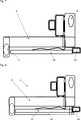
Ein nachfolgend exemplarisch beschriebenes Sensormodul ist als Umfeldkamera
Sie umfasst eine Trägerbasis
Hergestellt wird die Trägerbasis
Im selben Fertigungsprozessschritt oder alternativ in einem nachfolgenden separaten Fertigungsprozessschritt erfolgt zudem eine Umformung des Rohlings
Im weiteren Verlauf der Fertigung wird eine in
Sind die mittels der Leiterplatine
Während der Ausrichtung oder Justage des Bildsensors
Durch die unmittelbare Befestigung des Bildsensors
Für die Energieversorgung und die Signalübertragung hingegen wird der Bildsensor
In einem nachfolgenden Fertigungsprozessschritt wird dann eine vorgefertigte Optik
Wie in
Die Erfindung ist nicht auf das vorstehend beschriebene Ausführungsbeispiel beschränkt. Vielmehr können auch andere Varianten der Erfindung von dem Fachmann hieraus abgeleitet werden, ohne den Gegenstand der Erfindung zu verlassen. Insbesondere sind ferner alle im Zusammenhang mit dem Ausführungsbeispiel beschriebenen Einzelmerkmale auch auf andere Weise miteinander kombinierbar, ohne den Gegenstand der Erfindung zu verlassen.The invention is not limited to the embodiment described above. Rather, other variants of the invention can be derived therefrom by the person skilled in the art without departing from the subject matter of the invention. In particular, all the individual features described in connection with the exemplary embodiment can also be combined with each other in other ways, without departing from the subject matter of the invention.
BezugszeichenlisteLIST OF REFERENCE NUMBERS
- 22
- Umfeldkamera environment camera
- 44
- Kraftfahrzeug motor vehicle
- 66
- Trägerbasis support base
- 88th
- Kraftfahrzeugschnittstelle Motor vehicle interface
- 1010
- Rohling blank
- 1212
- Kabeldurchführung Grommet
- 1414
- Absorberbeschichtung absorber coating
- 1616
- flexible Leiterplatte flexible circuit board
- 1818
- Bildsensor image sensor
- 2020
- Verbindungsdraht connecting wire
- 2222
- Anschlusskontakt connection contact
- 2424
- Leiterbahn conductor path
- 2626
- Optik optics
- 2828
- Fassung version
- 3030
- Kleberaupe adhesive bead
- 3232
- Hauptplatine motherboard
- 3434
- Anschluss connection
- 3636
- Abdeckung cover
Claims (15)
Translated fromGermanPriority Applications (1)
| Application Number | Priority Date | Filing Date | Title |
|---|---|---|---|
| DE102015200943.2ADE102015200943A1 (en) | 2015-01-21 | 2015-01-21 | sensor module |
Applications Claiming Priority (1)
| Application Number | Priority Date | Filing Date | Title |
|---|---|---|---|
| DE102015200943.2ADE102015200943A1 (en) | 2015-01-21 | 2015-01-21 | sensor module |
Publications (1)
| Publication Number | Publication Date |
|---|---|
| DE102015200943A1true DE102015200943A1 (en) | 2016-07-21 |
Family
ID=56293783
Family Applications (1)
| Application Number | Title | Priority Date | Filing Date |
|---|---|---|---|
| DE102015200943.2APendingDE102015200943A1 (en) | 2015-01-21 | 2015-01-21 | sensor module |
Country Status (1)
| Country | Link |
|---|---|
| DE (1) | DE102015200943A1 (en) |
Cited By (2)
| Publication number | Priority date | Publication date | Assignee | Title |
|---|---|---|---|---|
| WO2018069184A3 (en)* | 2016-10-13 | 2018-06-07 | HELLA GmbH & Co. KGaA | Radar device comprising a shielding means |
| DE102017212610B4 (en) | 2017-07-21 | 2023-10-05 | Ford Global Technologies, Llc | Housing for accommodating and covering electrical or electronic components of a motor vehicle, motor vehicle with such a housing and method for producing such a housing |
Citations (18)
| Publication number | Priority date | Publication date | Assignee | Title |
|---|---|---|---|---|
| DE19651260A1 (en)* | 1996-12-10 | 1998-01-02 | Siemens Ag | Image sensor chip for video camera |
| DE19827044C1 (en)* | 1998-06-18 | 1999-10-21 | Daimler Chrysler Ag | Light and/or rain sensor device for motor vehicle |
| DE10209616A1 (en)* | 2002-03-05 | 2003-09-18 | Bosch Gmbh Robert | Method and device for fastening a sensor |
| DE60007249T2 (en)* | 1999-09-22 | 2004-05-27 | Fuji Jukogyo K.K. | Mounting structure for cameras on a motor vehicle |
| DE102004032749B3 (en)* | 2004-07-07 | 2006-01-05 | A. Raymond & Cie | Device for attaching a rain sensor to a carrier |
| DE102004042217A1 (en)* | 2004-09-01 | 2006-03-02 | Conti Temic Microelectronic Gmbh | Fastening device for sensor on especially curved surface such as windscreen of motor vehicle has housing with flexible section so that resulting deformability provides compensation for tolerances and curvature of surface |
| DE102006035991A1 (en)* | 2006-08-02 | 2008-02-14 | A. Raymond Et Cie | Device for holding a camera on a support |
| DE102010010571A1 (en)* | 2010-03-05 | 2011-09-08 | Conti Temic Microelectronic Gmbh | Fastening device for sensor housing in a motor vehicle interior |
| DE102010034029A1 (en)* | 2010-08-11 | 2012-02-16 | Conti Temic Microelectronic Gmbh | Sensor assembly e.g. optical sensor assembly for camera in motor car, has pressure generating element that generates low pressure in cavity of housing which is locked with disc in mounted state such that cavity is enclosed airtightly |
| DE102010047106A1 (en)* | 2010-10-01 | 2012-04-05 | Conti Temic Microelectronic Gmbh | Device, particularly optical device, has objective and carrier housing, where objective is mounted in carrier housing, and objective and carrier housing are connected with each other through adhesive connection |
| DE102011103302A1 (en)* | 2011-06-03 | 2012-12-06 | Conti Temic Microelectronic Gmbh | Camera system for a vehicle |
| DE102013200966A1 (en)* | 2012-02-10 | 2013-08-14 | Robert Bosch Gmbh | Modular device for a camera system and camera system |
| DE112012003221T5 (en)* | 2011-08-02 | 2014-04-24 | Magna Electronics, Inc. | Vehicle camera system |
| DE112012004978T5 (en)* | 2011-11-30 | 2014-08-28 | Hitachi Automotive Systems, Ltd. | Fastening device for vehicle cameras |
| DE102013205160A1 (en)* | 2013-03-22 | 2014-09-25 | Robert Bosch Gmbh | Camera system, in particular for a vehicle, and method for its production |
| DE102013205165A1 (en)* | 2013-03-22 | 2014-10-09 | Robert Bosch Gmbh | Camera arrangement for a vehicle and vehicle with such a camera arrangement |
| WO2015144262A1 (en)* | 2014-03-27 | 2015-10-01 | Conti Temic Microelectronic Gmbh | Camera system of a driver assistance system |
| DE102014208487A1 (en)* | 2014-05-07 | 2015-11-12 | Conti Temic Microelectronic Gmbh | Camera of an assistance system of a motor vehicle and method for producing such an assistance system |
- 2015
- 2015-01-21DEDE102015200943.2Apatent/DE102015200943A1/enactivePending
Patent Citations (18)
| Publication number | Priority date | Publication date | Assignee | Title |
|---|---|---|---|---|
| DE19651260A1 (en)* | 1996-12-10 | 1998-01-02 | Siemens Ag | Image sensor chip for video camera |
| DE19827044C1 (en)* | 1998-06-18 | 1999-10-21 | Daimler Chrysler Ag | Light and/or rain sensor device for motor vehicle |
| DE60007249T2 (en)* | 1999-09-22 | 2004-05-27 | Fuji Jukogyo K.K. | Mounting structure for cameras on a motor vehicle |
| DE10209616A1 (en)* | 2002-03-05 | 2003-09-18 | Bosch Gmbh Robert | Method and device for fastening a sensor |
| DE102004032749B3 (en)* | 2004-07-07 | 2006-01-05 | A. Raymond & Cie | Device for attaching a rain sensor to a carrier |
| DE102004042217A1 (en)* | 2004-09-01 | 2006-03-02 | Conti Temic Microelectronic Gmbh | Fastening device for sensor on especially curved surface such as windscreen of motor vehicle has housing with flexible section so that resulting deformability provides compensation for tolerances and curvature of surface |
| DE102006035991A1 (en)* | 2006-08-02 | 2008-02-14 | A. Raymond Et Cie | Device for holding a camera on a support |
| DE102010010571A1 (en)* | 2010-03-05 | 2011-09-08 | Conti Temic Microelectronic Gmbh | Fastening device for sensor housing in a motor vehicle interior |
| DE102010034029A1 (en)* | 2010-08-11 | 2012-02-16 | Conti Temic Microelectronic Gmbh | Sensor assembly e.g. optical sensor assembly for camera in motor car, has pressure generating element that generates low pressure in cavity of housing which is locked with disc in mounted state such that cavity is enclosed airtightly |
| DE102010047106A1 (en)* | 2010-10-01 | 2012-04-05 | Conti Temic Microelectronic Gmbh | Device, particularly optical device, has objective and carrier housing, where objective is mounted in carrier housing, and objective and carrier housing are connected with each other through adhesive connection |
| DE102011103302A1 (en)* | 2011-06-03 | 2012-12-06 | Conti Temic Microelectronic Gmbh | Camera system for a vehicle |
| DE112012003221T5 (en)* | 2011-08-02 | 2014-04-24 | Magna Electronics, Inc. | Vehicle camera system |
| DE112012004978T5 (en)* | 2011-11-30 | 2014-08-28 | Hitachi Automotive Systems, Ltd. | Fastening device for vehicle cameras |
| DE102013200966A1 (en)* | 2012-02-10 | 2013-08-14 | Robert Bosch Gmbh | Modular device for a camera system and camera system |
| DE102013205160A1 (en)* | 2013-03-22 | 2014-09-25 | Robert Bosch Gmbh | Camera system, in particular for a vehicle, and method for its production |
| DE102013205165A1 (en)* | 2013-03-22 | 2014-10-09 | Robert Bosch Gmbh | Camera arrangement for a vehicle and vehicle with such a camera arrangement |
| WO2015144262A1 (en)* | 2014-03-27 | 2015-10-01 | Conti Temic Microelectronic Gmbh | Camera system of a driver assistance system |
| DE102014208487A1 (en)* | 2014-05-07 | 2015-11-12 | Conti Temic Microelectronic Gmbh | Camera of an assistance system of a motor vehicle and method for producing such an assistance system |
Cited By (3)
| Publication number | Priority date | Publication date | Assignee | Title |
|---|---|---|---|---|
| WO2018069184A3 (en)* | 2016-10-13 | 2018-06-07 | HELLA GmbH & Co. KGaA | Radar device comprising a shielding means |
| US11442143B2 (en) | 2016-10-13 | 2022-09-13 | HELLA GmbH & Co. KGaA | Radar device with a shield |
| DE102017212610B4 (en) | 2017-07-21 | 2023-10-05 | Ford Global Technologies, Llc | Housing for accommodating and covering electrical or electronic components of a motor vehicle, motor vehicle with such a housing and method for producing such a housing |
Similar Documents
| Publication | Publication Date | Title |
|---|---|---|
| EP2363726B1 (en) | Compact laser rangefinder | |
| EP2008443B1 (en) | Method for assembling a camera module, and camera module | |
| DE102017124550A1 (en) | Camera for a motor vehicle with at least two printed circuit boards and improved electromagnetic shielding, camera system, motor vehicle and manufacturing method | |
| DE102013200966B4 (en) | Module device for a camera system and corresponding camera system | |
| DE60225384T2 (en) | INERTIA CONVERTER | |
| EP1458593A1 (en) | Stereo camera arrangement in a motor vehicle | |
| DE102016123752A1 (en) | SENSOR DEVICE | |
| WO2014146656A1 (en) | Camera module and method for the production thereof | |
| DE112016002445B4 (en) | Sensor device | |
| DE102021123051A1 (en) | Heating of a lens module of a camera for a motor vehicle | |
| JP2011166012A (en) | Electronic apparatus and camera | |
| DE102012106834A1 (en) | Method for aligning two image recording elements of a stereo camera system | |
| DE102017200817A1 (en) | FLEXIBLE LADDER RAIL FOR CONNECTING ELECTRONIC MODULES, ESPECIALLY MODULES OF A CAMERA PROVIDED FOR INSTALLATION IN A VEHICLE | |
| DE10344767B4 (en) | Optical module and optical system | |
| DE102015200943A1 (en) | sensor module | |
| DE102014208487B4 (en) | Camera of an assistance system of a motor vehicle and method for producing such an assistance system | |
| DE102008000823A1 (en) | Camera assembly for use in a vehicle and method for its manufacture | |
| EP1366313A1 (en) | Mechatronic transmission control | |
| EP2768701A1 (en) | Optical device for a vehicle | |
| DE102013205160A1 (en) | Camera system, in particular for a vehicle, and method for its production | |
| EP3256820B1 (en) | Transmission control module | |
| DE102015200582A1 (en) | Camera of a driver assistance system and driver assistance system of a motor vehicle | |
| WO2003105465A1 (en) | Optical module and optical system | |
| DE19820704A1 (en) | Electric distance regulating device fitted to front of motor vehicles | |
| DE102017130246B4 (en) | Rear-view device and motor vehicle |
Legal Events
| Date | Code | Title | Description |
|---|---|---|---|
| R163 | Identified publications notified | ||
| R012 | Request for examination validly filed | ||
| R081 | Change of applicant/patentee | Owner name:CONTINENTAL AUTONOMOUS MOBILITY GERMANY GMBH, DE Free format text:FORMER OWNER: CONTI TEMIC MICROELECTRONIC GMBH, 90411 NUERNBERG, DE Owner name:AUMOVIO AUTONOMOUS MOBILITY GERMANY GMBH, DE Free format text:FORMER OWNER: CONTI TEMIC MICROELECTRONIC GMBH, 90411 NUERNBERG, DE | |
| R081 | Change of applicant/patentee | Owner name:AUMOVIO AUTONOMOUS MOBILITY GERMANY GMBH, DE Free format text:FORMER OWNER: CONTINENTAL AUTONOMOUS MOBILITY GERMANY GMBH, 85057 INGOLSTADT, DE |