DE102015122844A1 - 3D measuring device with battery pack - Google Patents
3D measuring device with battery packDownload PDFInfo
- Publication number
- DE102015122844A1 DE102015122844A1DE102015122844.0ADE102015122844ADE102015122844A1DE 102015122844 A1DE102015122844 A1DE 102015122844A1DE 102015122844 ADE102015122844 ADE 102015122844ADE 102015122844 A1DE102015122844 A1DE 102015122844A1
- Authority
- DE
- Germany
- Prior art keywords
- battery pack
- battery
- measuring head
- measuring
- light beam
- Prior art date
- Legal status (The legal status is an assumption and is not a legal conclusion. Google has not performed a legal analysis and makes no representation as to the accuracy of the status listed.)
- Pending
Links
Images


Classifications
- G—PHYSICS
- G01—MEASURING; TESTING
- G01B—MEASURING LENGTH, THICKNESS OR SIMILAR LINEAR DIMENSIONS; MEASURING ANGLES; MEASURING AREAS; MEASURING IRREGULARITIES OF SURFACES OR CONTOURS
- G01B11/00—Measuring arrangements characterised by the use of optical techniques
- G01B11/002—Measuring arrangements characterised by the use of optical techniques for measuring two or more coordinates
- G—PHYSICS
- G01—MEASURING; TESTING
- G01C—MEASURING DISTANCES, LEVELS OR BEARINGS; SURVEYING; NAVIGATION; GYROSCOPIC INSTRUMENTS; PHOTOGRAMMETRY OR VIDEOGRAMMETRY
- G01C15/00—Surveying instruments or accessories not provided for in groups G01C1/00 - G01C13/00
- G01C15/002—Active optical surveying means
- G—PHYSICS
- G01—MEASURING; TESTING
- G01S—RADIO DIRECTION-FINDING; RADIO NAVIGATION; DETERMINING DISTANCE OR VELOCITY BY USE OF RADIO WAVES; LOCATING OR PRESENCE-DETECTING BY USE OF THE REFLECTION OR RERADIATION OF RADIO WAVES; ANALOGOUS ARRANGEMENTS USING OTHER WAVES
- G01S17/00—Systems using the reflection or reradiation of electromagnetic waves other than radio waves, e.g. lidar systems
- G01S17/02—Systems using the reflection of electromagnetic waves other than radio waves
- G01S17/06—Systems determining position data of a target
- G01S17/42—Simultaneous measurement of distance and other co-ordinates
- G—PHYSICS
- G01—MEASURING; TESTING
- G01S—RADIO DIRECTION-FINDING; RADIO NAVIGATION; DETERMINING DISTANCE OR VELOCITY BY USE OF RADIO WAVES; LOCATING OR PRESENCE-DETECTING BY USE OF THE REFLECTION OR RERADIATION OF RADIO WAVES; ANALOGOUS ARRANGEMENTS USING OTHER WAVES
- G01S7/00—Details of systems according to groups G01S13/00, G01S15/00, G01S17/00
- G01S7/48—Details of systems according to groups G01S13/00, G01S15/00, G01S17/00 of systems according to group G01S17/00
- G01S7/481—Constructional features, e.g. arrangements of optical elements
- G01S7/4811—Constructional features, e.g. arrangements of optical elements common to transmitter and receiver
- G01S7/4813—Housing arrangements
- H—ELECTRICITY
- H01—ELECTRIC ELEMENTS
- H01M—PROCESSES OR MEANS, e.g. BATTERIES, FOR THE DIRECT CONVERSION OF CHEMICAL ENERGY INTO ELECTRICAL ENERGY
- H01M50/00—Constructional details or processes of manufacture of the non-active parts of electrochemical cells other than fuel cells, e.g. hybrid cells
- H01M50/20—Mountings; Secondary casings or frames; Racks, modules or packs; Suspension devices; Shock absorbers; Transport or carrying devices; Holders
- H01M50/204—Racks, modules or packs for multiple batteries or multiple cells
- H01M50/207—Racks, modules or packs for multiple batteries or multiple cells characterised by their shape
- H01M50/213—Racks, modules or packs for multiple batteries or multiple cells characterised by their shape adapted for cells having curved cross-section, e.g. round or elliptic
- Y—GENERAL TAGGING OF NEW TECHNOLOGICAL DEVELOPMENTS; GENERAL TAGGING OF CROSS-SECTIONAL TECHNOLOGIES SPANNING OVER SEVERAL SECTIONS OF THE IPC; TECHNICAL SUBJECTS COVERED BY FORMER USPC CROSS-REFERENCE ART COLLECTIONS [XRACs] AND DIGESTS
- Y02—TECHNOLOGIES OR APPLICATIONS FOR MITIGATION OR ADAPTATION AGAINST CLIMATE CHANGE
- Y02E—REDUCTION OF GREENHOUSE GAS [GHG] EMISSIONS, RELATED TO ENERGY GENERATION, TRANSMISSION OR DISTRIBUTION
- Y02E60/00—Enabling technologies; Technologies with a potential or indirect contribution to GHG emissions mitigation
- Y02E60/10—Energy storage using batteries
Landscapes
- Physics & Mathematics (AREA)
- Engineering & Computer Science (AREA)
- General Physics & Mathematics (AREA)
- Radar, Positioning & Navigation (AREA)
- Remote Sensing (AREA)
- Computer Networks & Wireless Communication (AREA)
- Electromagnetism (AREA)
- General Chemical & Material Sciences (AREA)
- Electrochemistry (AREA)
- Chemical Kinetics & Catalysis (AREA)
- Chemical & Material Sciences (AREA)
- Length Measuring Devices By Optical Means (AREA)
- Optical Radar Systems And Details Thereof (AREA)
Abstract
Translated fromGermanDescription
Translated fromGermanDie Erfindung betrifft eine Vorrichtung mit den Merkmalen des Oberbegriffs des Anspruches 1.The invention relates to a device having the features of the preamble of claim 1.
Die
In der
Der Erfindung liegt die Aufgabe zu Grunde, eine Vorrichtung der eingangs genannten Art zu verbessern. Diese Aufgabe wird erfindungsgemäß durch eine Vorrichtung mit den Merkmalen des Anspruches 1 gelöst. Vorteilhafte Ausgestaltungen sind Gegenstand der Unteransprüche.The invention is based on the object to improve a device of the type mentioned. This object is achieved by a device with the features of claim 1. Advantageous embodiments are the subject of the dependent claims.
Als Energieversorgung für tragbare Datenverarbeitungs- oder Telekommunikationsgeräte, Werkzeuge oder sonstige kabellose Vorrichtungen sind quaderförmige Akkumulatoren üblich. Batteriepacks mit Einzelbatterien aus riesigen Großserien finden Anwendung, wenn genügend Bauraum oder die abzugebende Spannung bereits durch wenige Einzelzellen erreicht wird. Obgleich die Einzelbatterien oft durch eine Folie zusammengehalten werden, kann der Benutzer diese Einzelbatterien selber bedarfsweise austauschen.As a power supply for portable data processing or telecommunications equipment, tools or other wireless devices cuboid batteries are common. Battery packs with single batteries from huge large series are used, if sufficient space or the voltage to be given is already achieved by a few single cells. Although the individual batteries are often held together by a foil, the user can replace these individual batteries themselves as needed.
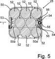
Die erfindungsgemäße Verwendung eines Batteriepacks nutzt der Vorteil der Beschaffung aus Großserien und eines vereinfachten Ersatzes, während sie den scheinbaren Nachteil des Bauraumsbedarfs durch die dichteste Packung ausgleicht. Die dichteste Packung bei länglichen Körpern mit kreisförmigem Querschnitt sind versetzte Reihen. Das Batteriegehäuse hält die Einzelbatterien zusammen.The use of a battery pack according to the invention takes advantage of the large-scale procurement and simplified replacement, while compensating for the apparent drawback of space requirements through the densest package. The densest packing in oblong bodies of circular cross section are staggered rows. The battery case holds the single batteries together.
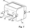
Durch den Versatz benachbarter Reihen um einen halben Durchmesser entstehen endseitig freie Ecken oder Zwischenräume. Damit einerseits das Batteriegehäuse möglichst wenig konkave Bereiche aufweist und andererseits diese Zwischenräume genutzt werden, ist eine Anordnung weiterer Bauteile des Batteriepacks sinnvoll, insbesondere des Batteriekontakts, der Schutzschaltung und der Riegel für die Verriegelung des Batteriepacks innerhalb des Messkopfes. Die Riegel der Verriegelung sind vorzugsweise multifunktional ausgebildet, indem sie zugleich die Halteelemente zum Einsetzen und Entnehmen des unverriegelten Batteriepacks bilden. Der Funktionswechsel erfolgt mit dem Verschieben der Riegel.By the offset of adjacent rows by half a diameter arise at the end free corners or spaces. On the one hand the battery housing has as few concave areas and on the other hand these spaces are used, an arrangement of other components of the battery pack is useful, especially the battery contact, the protection circuit and the latch for locking the battery pack within the measuring head. The latch of the lock are preferably designed to be multifunctional by at the same time form the holding elements for inserting and removing the unlocked battery pack. The function change takes place with the shifting of the bolts.
Vorzugsweise sind mehrere Mittel für ein verdrehsicheres Einsetzen des Batteriepacks vorgesehen. Neben den Abmessungen des Batteriegehäuses und der außermittigen Anordnung des Batteriekontaktes können am Batteriegehäuse Einbuchtungen und Vorsprünge vorgesehen sein, die mit passenden Mitteln am Aufnahmeschacht zusammenwirken. Wird der Batteriepack verdreht eingesetzt, kommen die Mittel so frühzeitig zum Einsatz, dass der Batteriekontakt vor Beschädigungen geschützt ist.Preferably, a plurality of means for a rotationally secure insertion of the battery pack are provided. In addition to the dimensions of the battery case and the eccentric arrangement of the battery contact indentations and projections may be provided on the battery case, which cooperate with appropriate means on the receiving shaft. If the battery pack is inserted twisted, the funds are used so early that the battery contact is protected against damage.
Eine Ladeschale für den Batteriepack ist auf die Position des Batteriekontaktes und der Mittel für ein verdrehsicheres Einsetzen des Batteriepacks abgestimmt. Mit den letztgenannten Mitteln kann der Batteriepack auch auf der Ladeschale fixiert werden.A charging tray for the battery pack is tuned to the position of the battery contact and the means for a non-rotatable insertion of the battery pack. With the latter means, the battery pack can also be fixed on the charging cradle.
Im Folgenden ist die Erfindung anhand eines in der Zeichnung dargestellten Ausführungsbeispiels mit Abwandlungen näher erläutert. Es zeigenIn the following the invention with reference to an embodiment shown in the drawing with modifications is explained in detail. Show it
Die vorliegende Erfindung betrifft eine 3D-(Koordinaten-)Messvorrichtung, die einen Lichtstrahl auf ein Objekt O lenkt, welches entweder ein (kooperatives) Target, beispielsweise ein Rückstrahler, oder ein nicht-kooperatives Target, beispielsweise eine diffus streuende Oberfläche des Objekts O, sein kann. Ein Entfernungsmesser in der 3D-Messvorrichtung misst eine Entfernung zum Objekt O (d. h. einen Abstand d zwischen der 3D-Messvorrichtung und dem Objekt O), und Drehwinkelgeber messen die Drehwinkel zweier Achsen im Gerät. Die gemessene Entfernung und die zwei Winkel ermöglichen einem Prozessor im Gerät, die 3D-Koordinaten des Objekts O zu bestimmen. Vorliegend wird als derartige 3D-Messvorrichtung der Fall eines Laserscanners
Laserscanner werden typischerweise dazu verwendet, geschlossene oder offene Räume, wie zum Beispiel Gebäudeinnenflächen, Industrieanlagen und Tunnels zu erfassen. Laserscanner werden für viele Zwecke, einschließlich Building Information Modeling (BIM), Industrieanalysen, Unfallrekonstruktionsanwendungen, archäologische Studien und forensische Untersuchungen eingesetzt. Ein Laserscanner kann eingesetzt werden, um Objekte in der Umgebung des Laserscanners durch die Erfassung von Datenpunkten, die Objekte innerhalb der Umgebung darstellen, optisch zu erfassen und zu vermessen. Solche Datenpunkte erhält man, indem ein Lichtstrahl auf die Objekte gelenkt und das reflektierte oder gestreute Licht gesammelt wird, um die Entfernung, zwei Winkel (d. h. einen Azimutwinkel und einen Zenitwinkel), und optional einen Graustufenwert zu ermitteln. Diese Roh-Scandaten werden gesammelt, gespeichert und an einen oder mehrere Rechner gesendet, um ein dreidimensionales Bild zu erzeugen, das den erfassten Bereich oder das erfasste Objekt darstellt. Zur Erzeugung des Bildes werden mindestens drei Werte für jeden Datenpunkt gesammelt. Diese drei Werte können die Entfernung und zwei Winkel umfassen, oder können umgewandelte Werte wie zum Beispiel x, y, z-Koordinaten sein.Laser scanners are typically used to detect closed or open spaces, such as building interiors, industrial facilities and tunnels. Laser scanners are used for many purposes including Building Information Modeling (BIM), industrial analysis, accident reconstruction applications, archaeological surveys and forensic investigations. A laser scanner can be used to optically detect and measure objects in the laser scanner environment by capturing data points that represent objects within the environment. Such data points are obtained by directing a light beam at the objects and collecting the reflected or scattered light to determine the distance, two angles (i.e., one azimuth angle and one zenith angle), and optionally a gray level value. This raw scan data is collected, stored and sent to one or more computers to generate a three-dimensional image representing the captured area or object. To generate the image, at least three values are collected for each data point. These three values may include the distance and two angles, or may be converted values such as x, y, z coordinates.
Die Zeichnung zeigt einen Laserscanner
Im vorliegenden Ausführungsbeispiel weist der Messkopf
Der Messkopf
Die Schale
Der Messkopf
Ein reflektierter Lichtstrahl, nachfolgend als Empfangslichtstrahl
Eine Steuer- und Auswertevorrichtung
Die Lichtgeschwindigkeit in Luft hängt von den Lufteigenschaften wie zum Beispiel Lufttemperatur, Luftdruck, relative Luftfeuchtigkeit und der Kohlendioxidkonzentration ab. Diese Lufteigenschaften beeinflussen den Brechungsindex der Luft. Die Lichtgeschwindigkeit in Luft entspricht der Lichtgeschwindigkeit im Vakuum geteilt durch den Brechungsindex. Ein Laserscanner der vorliegend beschriebenen Art beruht auf der Lichtlaufzeit in der Luft (der Laufzeit, die das Licht benötigt, um von der Vorrichtung bis zum Objekt und wieder zurück zur Vorrichtung zu gelangen). Eine Methode der Entfernungsmessung auf Grundlage der Lichtlaufzeit (oder der Laufzeit einer anderen elektromagnetischen Strahlungsart) hängt von der Lichtgeschwindigkeit in Luft ab und ist daher leicht von Methoden der Entfernungsmessung mittels Triangulation zu unterscheiden. Bei Methoden auf Grundlage von Triangulation wird Licht von seiner Lichtquelle in eine bestimmte Richtung ausgestrahlt und dann auf einem Kamerapixel in einer bestimmten Richtung aufgefangen. Dadurch, dass die Entfernung zwischen der Kamera und dem Projektor bekannt ist, und dass ein projizierter Winkel mit einem Empfangswinkel abgeglichen wird, ermöglicht die Triangulationsmethode die Bestimmung der Entfernung zum Objekt auf der Grundlage einer bekannten Länge und zweier bekannter Winkel eines Dreiecks. Die Triangulationsmethode hängt daher nicht direkt von der Lichtgeschwindigkeit in Luft ab.The speed of light in air depends on air properties such as air temperature, air pressure, relative humidity and carbon dioxide concentration. These air properties affect the refractive index of the air. The speed of light in air is the speed of light in vacuum divided by the refractive index. A laser scanner of the type described herein is based on the light transit time in the air (the transit time the light takes to travel from the device to the object and back to the device). A method of distance measurement based on the time of flight of light (or the duration of another type of electromagnetic radiation) depends on the speed of light in air and is therefore easily distinguished from triangulation distance measuring methods. In triangulation-based methods, light is emitted from its light source in a particular direction and then captured on a camera pixel in a particular direction. By knowing the distance between the camera and the projector and matching a projected angle with a reception angle, the triangulation method allows the determination of the distance to the object based on a known length and two known angles of a triangle. The Triangulation method is therefore not directly dependent on the speed of light in air.
Der Messkopf
Zusätzlich zur Distanz d vom Zentrum C10 zu einem Messpunkte X kann der Laserscanner
In einem bevorzugten Betriebsmodus des Laserscanners
In einem anderen bevorzugten Betriebsmodus des Laserscanners
Der Lichtsender
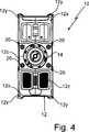
Der Batteriepack
Die Einzelbatterien
Die Riegel
Eine vorgespannte Riegel-Feder
Um den Batteriepack
Jeder Riegel
Die Abmessungen des Batteriepacks
Als weitere Verdrehsicherung ist der Batteriekontakt
Eine Ladeschale L für den Batteriepack
BezugszeichenlisteLIST OF REFERENCE NUMBERS
- 1010
- Laserscannerlaser scanner
- 1212
- Messkopfprobe
- 12a12a
- erste Achsefirst axis
- 12c12c
- Tragestruktursupport structure
- 12d12d
- Wandwall
- 12e12e
- Quertraversecrossbeam
- 12s12s
- SchaleBowl
- 12y12y
- Außenkanteouter edge
- 12z12z
- Kühlungcooling
- 1414
- Fußfoot
- 1616
- Spiegelmirror
- 16a16a
- zweite Achsesecond axis
- 1717
- Lichtsenderlight source
- 1818
- SendelichtstrahlTransmitted light beam
- 2020
- EmpfangslichtstrahlReception light beam
- 2121
- Lichtempfängerlight receiver
- 2222
- Steuer- und AuswertevorrichtungControl and evaluation device
- 2424
- Anweise- und AnzeigevorrichtungInstruction and display device
- 2525
- Farbkameracolor camera
- 2626
- Fixierungsmittelfixative
- 2828
- Batteriepackbattery Pack
- 5050
- Batteriegehäusebattery case
- 50a50a
- Zwischenraumgap
- 50b50b
- Einbuchtungindentation
- 50d50d
- Gehäusevorsprunghousing projection
- 5252
- EinzelbatterieSingle battery
- 5353
- Batteriekontaktbattery contact
- 5454
- Riegelbars
- 54a54a
- Griffelementhandle element
- 54b54b
- Versetzungtransfer
- 54d54d
- Anschlagattack
- 5656
- Führungsstiftguide pin
- 5757
- Stegweb
- 57d57d
- Gegenanschlagcounterstop
- 5858
- Riegel-FederLatch-spring
- C10C10
- Zentrumcenter
- dd
- Abstanddistance
- LL
- Ladeschalecharging cradle
- LcLc
- Aufnahmekontaktfemale contact
- LdLd
- Ladeschalen-VorsprungChargers Tab
- Lhlh
- Ladeschalen-HakenChargers hook
- OO
- Objektobject
- rr
- Reihenrichtungrow direction
- XX
- Messpunktmeasuring point
ZITATE ENTHALTEN IN DER BESCHREIBUNG QUOTES INCLUDE IN THE DESCRIPTION
Diese Liste der vom Anmelder aufgeführten Dokumente wurde automatisiert erzeugt und ist ausschließlich zur besseren Information des Lesers aufgenommen. Die Liste ist nicht Bestandteil der deutschen Patent- bzw. Gebrauchsmusteranmeldung. Das DPMA übernimmt keinerlei Haftung für etwaige Fehler oder Auslassungen.This list of the documents listed by the applicant has been generated automatically and is included solely for the better information of the reader. The list is not part of the German patent or utility model application. The DPMA assumes no liability for any errors or omissions.
Zitierte PatentliteraturCited patent literature
- DE 102009055988 B3[0002]DE 102009055988 B3[0002]
- EP 2005112 B1[0002]EP 2005112 B1[0002]
- DE 102009015922 A1[0003]DE 102009015922 A1[0003]
Claims (10)
Translated fromGermanPriority Applications (3)
| Application Number | Priority Date | Filing Date | Title |
|---|---|---|---|
| DE102015122844.0ADE102015122844A1 (en) | 2015-12-27 | 2015-12-27 | 3D measuring device with battery pack |
| US15/386,785US10175037B2 (en) | 2015-12-27 | 2016-12-21 | 3-D measuring device with battery pack |
| GB1622190.5AGB2547762A (en) | 2015-12-27 | 2016-12-23 | 3-D measuring device with battery pack |
Applications Claiming Priority (1)
| Application Number | Priority Date | Filing Date | Title |
|---|---|---|---|
| DE102015122844.0ADE102015122844A1 (en) | 2015-12-27 | 2015-12-27 | 3D measuring device with battery pack |
Publications (1)
| Publication Number | Publication Date |
|---|---|
| DE102015122844A1true DE102015122844A1 (en) | 2017-06-29 |
Family
ID=58360588
Family Applications (1)
| Application Number | Title | Priority Date | Filing Date |
|---|---|---|---|
| DE102015122844.0APendingDE102015122844A1 (en) | 2015-12-27 | 2015-12-27 | 3D measuring device with battery pack |
Country Status (3)
| Country | Link |
|---|---|
| US (1) | US10175037B2 (en) |
| DE (1) | DE102015122844A1 (en) |
| GB (1) | GB2547762A (en) |
Families Citing this family (3)
| Publication number | Priority date | Publication date | Assignee | Title |
|---|---|---|---|---|
| JP6966184B2 (en)* | 2016-06-15 | 2021-11-10 | 株式会社トプコン | Surveying system |
| DE102016119155A1 (en)* | 2016-09-15 | 2018-03-15 | Zoller + Fröhlich GmbH | laser scanner |
| CN110507034A (en)* | 2019-09-17 | 2019-11-29 | 福建(泉州)哈工大工程技术研究院 | A foot scanner |
Citations (7)
| Publication number | Priority date | Publication date | Assignee | Title |
|---|---|---|---|---|
| EP0905803A1 (en)* | 1997-09-30 | 1999-03-31 | Japan Storage Battery Co., Ltd. | Battery Holder |
| DE102004043828A1 (en)* | 2004-09-10 | 2006-03-16 | Robert Bosch Gmbh | battery Pack |
| DE102009015922A1 (en) | 2009-03-25 | 2010-10-07 | Faro Technologies, Inc., Lake Mary | Method for optically scanning and measuring a scene |
| DE102009055988B3 (en) | 2009-11-20 | 2011-03-17 | Faro Technologies, Inc., Lake Mary | Device, particularly laser scanner, for optical scanning and measuring surrounding area, has light transmitter that transmits transmission light ray by rotor mirror |
| WO2012038142A1 (en)* | 2010-09-23 | 2012-03-29 | Robert Bosch Gmbh | Battery compartment with communication interface as well as measurement instrument with the battery compartment |
| EP2005112B1 (en) | 2006-03-31 | 2014-02-26 | Faro Technologies Inc. | Apparatus and method for three-dimensional coverage of a spatial area |
| WO2014159799A1 (en)* | 2013-03-13 | 2014-10-02 | Faro Technologies, Inc. | Laser scanner with cellular transceiver communication |
Family Cites Families (737)
| Publication number | Priority date | Publication date | Assignee | Title |
|---|---|---|---|---|
| US1535312A (en) | 1923-09-15 | 1925-04-28 | Hosking Richard Thomas | Waterproof covering for cameras |
| US1538758A (en) | 1924-09-17 | 1925-05-19 | Taylor Claude Hunter | Piston ring |
| US1918813A (en) | 1932-02-02 | 1933-07-18 | Kinzy Jacob | Camera case |
| US2316573A (en) | 1940-04-01 | 1943-04-13 | W & L E Gurley | Instrument case |
| US2333243A (en) | 1942-12-07 | 1943-11-02 | Morrison Brothers Company | Detachable coupling |
| US2748926A (en) | 1952-03-17 | 1956-06-05 | Matthew T Leahy | Micrometer support |
| US2983367A (en) | 1958-06-25 | 1961-05-09 | Lee W Parmater | Plural instrument carrying case |
| US2924495A (en) | 1958-09-15 | 1960-02-09 | Merz Engineering Inc | Instrument case |
| GB894320A (en) | 1959-03-13 | 1962-04-18 | Famatex G M B H Fabrik Fur Tex | Tentering device |
| US2966257A (en) | 1959-11-03 | 1960-12-27 | Gen Radio Co | Instrument carrying case |
| GB1112941A (en) | 1965-01-02 | 1968-05-08 | Smiths Industries Ltd | Improvements in or relating to scanning apparatus |
| AT307762B (en) | 1971-04-28 | 1973-06-12 | Eumig | Method and device for distance measurement |
| US3945729A (en) | 1974-12-30 | 1976-03-23 | Stanford Research Institute | Combined ranging and color sensor |
| JPS5581525A (en) | 1978-12-11 | 1980-06-19 | Sumitomo Cement Co | Production of artificial gravel for gravel cultivation |
| SE425331B (en) | 1979-01-17 | 1982-09-20 | Erling Nilsson | DEVICE FOR DETECTING CIRCULAR RUBBING IN A PATIENT'S EXTREMITER BASED ON THE SKIN TEMPERATURE OF THE EXTREMITES |
| US4667231A (en) | 1979-09-07 | 1987-05-19 | Diffracto Ltd. | Electro-optical part inspection in the presence of contamination and surface finish variation |
| DE2950138C2 (en) | 1979-12-13 | 1985-12-19 | Bernhard 8071 Lenting Kessel | Plate system, especially for containers or the like. |
| DE3016609A1 (en) | 1980-04-30 | 1981-11-05 | G.L. Rexroth Gmbh, 8770 Lohr | Radial vane type pump - has throughput controlled by positioning valve energised by signal from discharge flow meter |
| US4340008A (en) | 1980-09-22 | 1982-07-20 | Mendelson Ralph R | Tilt indicator for shipping containers |
| JPS57132015A (en) | 1981-02-09 | 1982-08-16 | Kosaka Kenkyusho:Kk | Coordinate transformation device |
| US4457625A (en) | 1981-07-13 | 1984-07-03 | Itek Corporation | Self calibrating contour measuring system using fringe counting interferometers |
| JPS5827264A (en) | 1981-08-12 | 1983-02-17 | Omron Tateisi Electronics Co | Abnormal processing method for complex transaction in transaction processing device |
| DD201245A1 (en) | 1981-10-16 | 1983-07-13 | Rolf Jurenz | OPTICAL ARRANGEMENT FOR AUTOMATIC SHARPENING |
| US4506448A (en) | 1981-10-27 | 1985-03-26 | British Aerospace Public Limited Company | Teaching robots |
| US4424899A (en) | 1982-03-08 | 1984-01-10 | Western Electric Co., Inc. | Instrument carrying case |
| JPS58171291A (en) | 1982-03-31 | 1983-10-07 | 三菱電機株式会社 | Robot tilt angle detection device |
| JPS59133890A (en) | 1983-01-19 | 1984-08-01 | 市野 勝男 | Multitubular connecting joint device aiming at integral opposite arrangement of plurality of piping for same diameter |
| DE3340317A1 (en) | 1983-11-08 | 1984-08-16 | Walter 4790 Paderborn Hesse | Test set for the simultaneous orientation and height determination of points in cavities where access is difficult |
| US4664588A (en) | 1984-03-09 | 1987-05-12 | Applied Robotics Inc. | Apparatus and method for connecting and exchanging remote manipulable elements to a central control source |
| US4676002A (en) | 1984-06-25 | 1987-06-30 | Slocum Alexander H | Mechanisms to determine position and orientation in space |
| JPS6162885A (en) | 1984-09-05 | 1986-03-31 | Matsushita Electric Ind Co Ltd | distance speedometer |
| JPS61157095A (en) | 1984-12-28 | 1986-07-16 | Toshiba Corp | phase locked circuit |
| US4659280A (en) | 1985-01-22 | 1987-04-21 | Gmf Robotics Corporation | Robot with balancing mechanism having a variable counterbalance force |
| US4663852A (en) | 1985-09-19 | 1987-05-12 | Digital Electronic Automation, Inc | Active error compensation in a coordinated measuring machine |
| US4767257A (en) | 1985-12-23 | 1988-08-30 | Mitsubishi Denki Kabushiki Kaisha | Industrial robot |
| US4996909A (en) | 1986-02-14 | 1991-03-05 | Vache John P | Housing for remote environmental monitor system |
| US4714339B2 (en) | 1986-02-28 | 2000-05-23 | Us Commerce | Three and five axis laser tracking systems |
| DE3623343C1 (en) | 1986-07-11 | 1989-12-21 | Bodenseewerk Geraetetech | Optical viewfinder with rosette scanning |
| US5969321A (en) | 1986-08-08 | 1999-10-19 | Norand Corporation | Hand-held optically readable information set reader with operation over a range of distances |
| US5576529A (en) | 1986-08-08 | 1996-11-19 | Norand Technology Corporation | Hand-held optically readable information set reader focus with operation over a range of distances |
| FR2603228B1 (en) | 1986-08-28 | 1989-06-02 | Aerospatiale | PROCESS FOR PRODUCING RIGID LINKS OF COMPOSITE MATERIAL AND LINKS OF ROBOT ARMS INCLUDING APPLICATION. |
| WO1988001924A1 (en) | 1986-09-12 | 1988-03-24 | Raychem Corporation | Manipulator |
| JPS63135814A (en) | 1986-11-28 | 1988-06-08 | Hitachi Constr Mach Co Ltd | Apparatus for controlling posture of probe |
| US4790651A (en) | 1987-09-30 | 1988-12-13 | Chesapeake Laser Systems, Inc. | Tracking laser interferometer |
| US4870274A (en) | 1987-12-07 | 1989-09-26 | Micro Video, Inc. | Laser scanner with rotating mirror and housing which is transparent to the scanning radiation |
| US4964062A (en) | 1988-02-16 | 1990-10-16 | Ubhayakar Shivadev K | Robotic arm systems |
| US5069524A (en) | 1988-03-07 | 1991-12-03 | Honda Giken Kogyo Kabushiki Kaisha | Robot hand optical fiber connector coupling assembly |
| US4882806A (en) | 1988-07-11 | 1989-11-28 | Davis Thomas J | Counterbalancing torsion spring mechanism for devices which move up and down and method of setting the torsion springs thereof |
| US6889903B1 (en) | 1988-08-31 | 2005-05-10 | Intermec Ip Corp. | Method and apparatus for optically reading information |
| US5205111A (en) | 1989-06-20 | 1993-04-27 | Johnson Level & Tool Mfg. Co., Inc. | Packaging method for a level and case |
| US5027951A (en) | 1989-06-20 | 1991-07-02 | Johnson Level & Tool Mfg. Co., Inc. | Apparatus and method for packaging of articles |
| JP2916687B2 (en) | 1989-07-27 | 1999-07-05 | 飛島建設株式会社 | Automatic surveying equipment |
| CA2038818A1 (en) | 1990-03-30 | 1991-10-01 | Akio Nagamune | Distance measuring method and apparatus therefor |
| US5675326A (en) | 1990-04-11 | 1997-10-07 | Auto-Sense, Ltd. | Method of determining optimal detection beam locations using reflective feature mapping |
| US5025966A (en) | 1990-05-07 | 1991-06-25 | Potter Stephen B | Magnetic tool holder |
| US5168532A (en) | 1990-07-02 | 1992-12-01 | Varian Associates, Inc. | Method for improving the dynamic range of an imaging system |
| IL95205A0 (en) | 1990-07-27 | 1991-06-10 | Optrotech Ltd | Method and apparatus for optical inspection of substrates |
| SE466726B (en) | 1990-08-20 | 1992-03-23 | Kent Lennartsson | DISTRIBUTED COMPUTER SYSTEM DEVICE |
| DE4027990C1 (en) | 1990-09-04 | 1992-02-20 | Messerschmitt-Boelkow-Blohm Gmbh, 8012 Ottobrunn, De | Laser ranging device - uses modulated semiconductor laser and phase sensitive rectifier |
| JPH04115108A (en) | 1990-09-05 | 1992-04-16 | Matsushita Electric Ind Co Ltd | Three-dimensional scanner |
| US5371347A (en) | 1991-10-15 | 1994-12-06 | Gap Technologies, Incorporated | Electro-optical scanning system with gyrating scan head |
| US5124524A (en) | 1990-11-15 | 1992-06-23 | Laser Design Inc. | Laser alignment and control system |
| JPH04225188A (en) | 1990-12-27 | 1992-08-14 | Nec Corp | Object classification device |
| JP2969009B2 (en) | 1991-02-22 | 1999-11-02 | 株式会社リコー | Axial mirror deflector |
| US5211476A (en) | 1991-03-04 | 1993-05-18 | Allflex Europe S.A. | Temperature recording system |
| FR2674017B1 (en) | 1991-03-12 | 1995-01-13 | Romer Srl | DEVICE FOR MEASURING THE SHAPE OR POSITION OF AN OBJECT. |
| CA2065482A1 (en) | 1991-04-11 | 1992-10-12 | Akira Inoue | Method and apparatus for measuring a coating state |
| JP3189843B2 (en) | 1991-04-15 | 2001-07-16 | ソニー株式会社 | Camera case |
| US5332315A (en) | 1991-04-27 | 1994-07-26 | Gec Avery Limited | Apparatus and sensor unit for monitoring changes in a physical quantity with time |
| US5373346A (en) | 1991-06-13 | 1994-12-13 | Onset Computer Corp. | Data gathering computer and analysis display computer interface system and methodology |
| US5239855A (en) | 1991-07-12 | 1993-08-31 | Hewlett-Packard Company | Positional calibration of robotic arm joints relative to the gravity vector |
| US5231470A (en) | 1991-09-06 | 1993-07-27 | Koch Stephen K | Scanning system for three-dimensional object digitizing |
| JPH0572477A (en) | 1991-09-13 | 1993-03-26 | Toshiba Corp | Afocal optical device |
| DE4134546A1 (en) | 1991-09-26 | 1993-04-08 | Steinbichler Hans | METHOD AND DEVICE FOR DETERMINING THE ABSOLUTE COORDINATES OF AN OBJECT |
| KR930007660A (en) | 1991-10-29 | 1993-05-20 | 오오가 노리오 | Image drawing device |
| GB9126269D0 (en) | 1991-12-11 | 1992-02-12 | Renishaw Metrology Ltd | Temperature sensor for coordinate positioning apparatus |
| US5918029A (en) | 1996-09-27 | 1999-06-29 | Digital Equipment Corporation | Bus interface slicing mechanism allowing for a control/data-path slice |
| DE4222642A1 (en) | 1992-07-10 | 1994-01-13 | Bodenseewerk Geraetetech | Imaging sensor unit |
| US5313261A (en) | 1992-07-13 | 1994-05-17 | Applied Remote Technology Inc. | Method and apparatus for faithful gray scale representation of under water laser images |
| US5319445A (en) | 1992-09-08 | 1994-06-07 | Fitts John M | Hidden change distribution grating and use in 3D moire measurement sensors and CMM applications |
| US5329347A (en) | 1992-09-16 | 1994-07-12 | Varo Inc. | Multifunction coaxial objective system for a rangefinder |
| DE4327250C5 (en) | 1992-09-25 | 2008-11-20 | Carl Zeiss Industrielle Messtechnik Gmbh | Method for measuring coordinates on workpieces |
| US5402365A (en) | 1992-10-28 | 1995-03-28 | Motorola, Inc. | Differential odometer dynamic calibration method and apparatus therefor |
| US5337149A (en) | 1992-11-12 | 1994-08-09 | Kozah Ghassan F | Computerized three dimensional data acquisition apparatus and method |
| DE4340756C5 (en) | 1992-12-08 | 2006-08-10 | Sick Ag | Laser range finding device |
| DE4303804C2 (en) | 1993-02-10 | 1996-06-27 | Leuze Electronic Gmbh & Co | Distance measuring device |
| US5412880A (en) | 1993-02-23 | 1995-05-09 | Faro Technologies Inc. | Method of constructing a 3-dimensional map of a measurable quantity using three dimensional coordinate measuring apparatus |
| US5611147A (en) | 1993-02-23 | 1997-03-18 | Faro Technologies, Inc. | Three dimensional coordinate measuring apparatus |
| US5402582A (en) | 1993-02-23 | 1995-04-04 | Faro Technologies Inc. | Three dimensional coordinate measuring apparatus |
| US6535794B1 (en) | 1993-02-23 | 2003-03-18 | Faro Technologoies Inc. | Method of generating an error map for calibration of a robot or multi-axis machining center |
| JPH06313710A (en) | 1993-04-28 | 1994-11-08 | Hitachi Plant Eng & Constr Co Ltd | Arm extension apparatus for three-dimensional space coordinate measuring machine |
| JP3256332B2 (en) | 1993-05-24 | 2002-02-12 | 郁男 荒井 | Distance measuring method and distance measuring device |
| US5455670A (en) | 1993-05-27 | 1995-10-03 | Associated Universities, Inc. | Optical electronic distance measuring apparatus with movable mirror |
| JP2859514B2 (en) | 1993-05-31 | 1999-02-17 | 株式会社カイジョー | Doppler shift correction pulse type fishing net depth gauge |
| US5724264A (en) | 1993-07-16 | 1998-03-03 | Immersion Human Interface Corp. | Method and apparatus for tracking the position and orientation of a stylus and for digitizing a 3-D object |
| US6553130B1 (en) | 1993-08-11 | 2003-04-22 | Jerome H. Lemelson | Motor vehicle warning and control system and method |
| FR2710407B1 (en) | 1993-09-20 | 1995-12-01 | Romer Srl | Positioning method for a three-dimensional measuring machine and device for implementing the method. |
| JPH07128051A (en) | 1993-11-02 | 1995-05-19 | Sekisui Chem Co Ltd | Unevenness survey system |
| JPH07209080A (en) | 1993-12-28 | 1995-08-11 | Amberg Measuring Technik Ltd | Optical scanning device |
| JPH07210586A (en) | 1994-01-13 | 1995-08-11 | Nikon Corp | Device for optimizing probe path of three-dimensional coordinate measuring machine |
| IL108646A0 (en) | 1994-02-14 | 1995-03-15 | Israel State | Opto-mechanical system |
| JPH07229963A (en) | 1994-02-21 | 1995-08-29 | Oki Electric Ind Co Ltd | Method for track detection |
| DE4410775C2 (en) | 1994-03-28 | 2000-04-06 | Daimler Chrysler Ag | Control unit and operating method of an operating system for this control unit |
| DE4412044A1 (en) | 1994-04-08 | 1995-10-12 | Leuze Electronic Gmbh & Co | Opto-electronic system for detecting objects in monitoring region |
| JPH0821714A (en) | 1994-05-06 | 1996-01-23 | Tokimec Inc | Road-surface shape measuring device |
| JPH0815413A (en) | 1994-06-24 | 1996-01-19 | Mitsubishi Electric Corp | Distance measuring device |
| US5430384A (en) | 1994-07-22 | 1995-07-04 | Onset Computer Corp. | Temperature compensated soil moisture sensor |
| US5510977A (en) | 1994-08-02 | 1996-04-23 | Faro Technologies Inc. | Method and apparatus for measuring features of a part or item |
| JP3619545B2 (en) | 1994-08-23 | 2005-02-09 | オリンパス株式会社 | Camera ranging device |
| JPH0876039A (en) | 1994-09-08 | 1996-03-22 | Fuji Xerox Co Ltd | Multi-beam laser recorder |
| US5517297A (en) | 1994-10-13 | 1996-05-14 | Hughes Aircraft Company | Rangefinder with transmitter, receiver, and viewfinder on a single common optical axis |
| JPH08129145A (en) | 1994-11-01 | 1996-05-21 | Nec Eng Ltd | Rotary deflection unit |
| JPH08136849A (en) | 1994-11-08 | 1996-05-31 | Konica Corp | Optical scanner |
| JP3428182B2 (en) | 1994-11-18 | 2003-07-22 | 株式会社ニコン | Surveying instrument |
| JPH08166813A (en) | 1994-12-14 | 1996-06-25 | Fanuc Ltd | Tracking control method for robot accompanied by weaving operation |
| US5793993A (en) | 1995-01-26 | 1998-08-11 | General Magic, Inc. | Method for transmitting bus commands and data over two wires of a serial bus |
| US5535524A (en) | 1995-01-27 | 1996-07-16 | Brown & Sharpe Manufacturing Company | Vibration damper for coordinate measuring machine |
| JP3582918B2 (en) | 1995-02-14 | 2004-10-27 | 株式会社トプコン | Laser surveying machine |
| JPH08262361A (en) | 1995-03-17 | 1996-10-11 | Ebara Corp | Attaching structure for polygon mirror |
| JPH08262140A (en) | 1995-03-20 | 1996-10-11 | Tokyo Gas Co Ltd | Beam tilt mechanism for laser radar and laser device using the tilt mechanism |
| CN2236119Y (en) | 1995-03-22 | 1996-09-25 | 付文博 | Single-jig measuring machine |
| US5682508A (en) | 1995-03-23 | 1997-10-28 | Onset Computer Corporation | UART protocol that provides predictable delay for communication between computers of disparate ability |
| US5754449A (en) | 1995-04-25 | 1998-05-19 | Instrumented Sensor Technology, Inc. | Method and apparatus for recording time history data of physical variables |
| US5825666A (en) | 1995-06-07 | 1998-10-20 | Freifeld; Daniel | Optical coordinate measuring machines and optical touch probes |
| DE19521771A1 (en) | 1995-06-20 | 1997-01-02 | Jan Michael Mrosik | FMCW distance measuring method |
| JP2729362B2 (en) | 1995-07-05 | 1998-03-18 | 防衛庁技術研究本部長 | Automatic target classifier |
| GB9515311D0 (en) | 1995-07-26 | 1995-09-20 | 3D Scanners Ltd | Stripe scanners and methods of scanning |
| US6697748B1 (en) | 1995-08-07 | 2004-02-24 | Immersion Corporation | Digitizing system and rotary table for determining 3-D geometry of an object |
| US5832416A (en) | 1995-09-01 | 1998-11-03 | Brown & Sharpe Manufacturing Company | Calibration system for coordinate measuring machine |
| DE19534535C2 (en) | 1995-09-18 | 2000-05-31 | Leitz Mestechnik Gmbh | Coordinate measuring machine |
| US6204961B1 (en) | 1995-09-18 | 2001-03-20 | Litton Systems, Inc. | Day and night sighting system |
| DE29515738U1 (en) | 1995-10-04 | 1995-11-30 | Vosseler, Hans-Günther, 74613 Öhringen | Measuring device for non-contact measurement analysis of bodies or surfaces |
| NO301999B1 (en) | 1995-10-12 | 1998-01-05 | Metronor As | Combination of laser tracker and camera based coordinate measurement |
| US5762512A (en)* | 1995-10-12 | 1998-06-09 | Symbol Technologies, Inc. | Latchable battery pack for battery-operated electronic device having controlled power shutdown and turn on |
| DE69634771T2 (en) | 1995-10-30 | 2006-02-02 | Kabushiki Kaisha Topcon | ROTATION LASER SYSTEM |
| DE19543763B4 (en) | 1995-11-24 | 2005-07-21 | Leitz Messtechnik Gmbh | Method for automatically detecting different sensors in coordinate measuring machines and devices for carrying out the method |
| US20020014533A1 (en) | 1995-12-18 | 2002-02-07 | Xiaxun Zhu | Automated object dimensioning system employing contour tracing, vertice detection, and forner point detection and reduction methods on 2-d range data maps |
| DE19601875C2 (en) | 1996-01-19 | 1999-08-19 | Siemens Ag | Method and device for eliminating interference from FMCW radar |
| US6460004B2 (en) | 1996-02-06 | 2002-10-01 | Perceptron, Inc. | Method and apparatus for calibrating a non-contact gauging sensor with respect to an external coordinate system |
| US6134507A (en) | 1996-02-06 | 2000-10-17 | Perceptron, Inc. | Method and apparatus for calibrating a non-contact gauging sensor with respect to an external coordinate system |
| US5768792A (en) | 1996-02-09 | 1998-06-23 | Faro Technologies Inc. | Method and apparatus for measuring and tube fitting |
| DE19607345A1 (en) | 1996-02-27 | 1997-08-28 | Sick Ag | Laser distance determination device |
| US5936721A (en) | 1996-03-18 | 1999-08-10 | Kabushiki Kaisha Topcon | Guide beam direction setting apparatus |
| JP3797704B2 (en) | 1996-04-05 | 2006-07-19 | 株式会社ミツトヨ | Optical measuring device |
| US5831719A (en) | 1996-04-12 | 1998-11-03 | Holometrics, Inc. | Laser scanning system |
| US5829148A (en) | 1996-04-23 | 1998-11-03 | Eaton; Homer L. | Spatial measuring device |
| US5988862A (en) | 1996-04-24 | 1999-11-23 | Cyra Technologies, Inc. | Integrated system for quickly and accurately imaging and modeling three dimensional objects |
| JPH102714A (en) | 1996-06-19 | 1998-01-06 | Canon Inc | Measurement method and device |
| US6057915A (en) | 1996-06-21 | 2000-05-02 | Thermotrex Corporation | Projectile tracking system |
| JPH1054111A (en) | 1996-08-09 | 1998-02-24 | Seinan Sogo Kaihatsu Kk | Tile with solar battery |
| JP3691166B2 (en)* | 1996-08-09 | 2005-08-31 | 株式会社ソキア | Surveyor battery pack attachment / detachment mechanism |
| CA2183004A1 (en) | 1996-08-23 | 1998-02-24 | Nino Camurri | Articulated-arm measuring machine and twist-net network |
| JP3842876B2 (en) | 1996-09-27 | 2006-11-08 | 株式会社リコー | Digital camera |
| KR100268048B1 (en) | 1996-10-28 | 2000-11-01 | 고바야시 마사키 | Underwater laser imaging apparatus |
| US5752112A (en) | 1996-11-06 | 1998-05-12 | George Paddock, Inc. | Mounting system for body mounted camera equipment |
| US5926782A (en) | 1996-11-12 | 1999-07-20 | Faro Technologies Inc | Convertible three dimensional coordinate measuring machine |
| DE19647152A1 (en) | 1996-11-14 | 1998-05-28 | Sick Ag | Laser distance determination device |
| DE29622033U1 (en) | 1996-12-18 | 1997-02-27 | Siemens AG, 80333 München | Control panel with integrated control elements and a display unit |
| US5997779A (en) | 1996-12-18 | 1999-12-07 | Aki Dryer Manufacturer, Inc. | Temperature monitor for gypsum board manufacturing |
| GB9626825D0 (en) | 1996-12-24 | 1997-02-12 | Crampton Stephen J | Avatar kiosk |
| US6282195B1 (en) | 1997-01-09 | 2001-08-28 | Silicon Graphics, Inc. | Packetized data transmissions in a switched router architecture |
| JPH10246863A (en) | 1997-03-05 | 1998-09-14 | Sankyo Seiki Mfg Co Ltd | Rotating polygon mirror type light deflector |
| WO1998044287A1 (en) | 1997-03-28 | 1998-10-08 | Thieltges Gary P | Motion stable camera support system |
| DE19720049B4 (en) | 1997-05-14 | 2006-01-19 | Hexagon Metrology Gmbh | Method for controlling a motor coordinate measuring machine and coordinate measuring machine for carrying out the method |
| US5956857A (en) | 1997-05-19 | 1999-09-28 | Faro Technologies, Inc. | Mounting device for a coordinate measuring machine |
| DE19722969C1 (en) | 1997-05-31 | 1998-09-03 | Weinhold Karl | Pipe coupling with C=shaped shells |
| US5983936A (en) | 1997-06-12 | 1999-11-16 | The Dover Corporation | Torsion spring balance assembly and adjustment method |
| JP3383187B2 (en) | 1997-07-09 | 2003-03-04 | 株式会社三協精機製作所 | Optical deflector |
| US6339410B1 (en) | 1997-07-22 | 2002-01-15 | Tellassist, Inc. | Apparatus and method for language translation between patient and caregiver, and for communication with speech deficient patients |
| US6069700A (en) | 1997-07-31 | 2000-05-30 | The Boeing Company | Portable laser digitizing system for large parts |
| US6408252B1 (en) | 1997-08-01 | 2002-06-18 | Dynalog, Inc. | Calibration system and displacement measurement device |
| US6060889A (en) | 1998-02-11 | 2000-05-09 | Onset Computer Corporation | Sensing water and moisture using a delay line |
| DE19806288A1 (en) | 1998-02-16 | 1999-08-26 | Fraunhofer Ges Forschung | Laser scanner measuring system |
| EP1062525B1 (en) | 1998-03-10 | 2003-05-14 | Riegl Laser Measurement Systems Gmbh | Method for monitoring objects or an object area |
| DE19811550C2 (en) | 1998-03-18 | 2002-06-27 | Bosch Gmbh Robert | Method and circuit arrangement for generating frequency signals |
| EP0949524A1 (en) | 1998-04-07 | 1999-10-13 | Fujifilm Electronic Imaging Limited | Rotatable mirror assembly |
| DE19816270A1 (en) | 1998-04-11 | 1999-10-21 | Werth Messtechnik Gmbh | Method and arrangement for detecting the geometry of objects using a coordinate measuring machine |
| EP0952427B1 (en) | 1998-04-24 | 2004-03-03 | Inco Limited | Automated guided apparatus |
| DE19820307C2 (en) | 1998-05-07 | 2003-01-02 | Mycrona Ges Fuer Innovative Me | Non-contact temperature detection on a multi-coordinate measuring and testing device |
| US6240651B1 (en) | 1998-06-17 | 2001-06-05 | Mycrona Gmbh | Coordinate measuring machine having a non-sensing probe |
| US5996790A (en) | 1998-06-26 | 1999-12-07 | Asahi Research Corporation | Watertight equipment cover |
| US6131299A (en) | 1998-07-01 | 2000-10-17 | Faro Technologies, Inc. | Display device for a coordinate measurement machine |
| US6151789A (en) | 1998-07-01 | 2000-11-28 | Faro Technologies Inc. | Adjustable handgrip for a coordinate measurement machine |
| US5978748A (en) | 1998-07-07 | 1999-11-02 | Faro Technologies, Inc. | Host independent articulated arm |
| US6219928B1 (en) | 1998-07-08 | 2001-04-24 | Faro Technologies Inc. | Serial network for coordinate measurement apparatus |
| USD441632S1 (en) | 1998-07-20 | 2001-05-08 | Faro Technologies Inc. | Adjustable handgrip |
| GB2341203A (en) | 1998-09-01 | 2000-03-08 | Faro Tech Inc | Flat web coupler for coordinate measurement systems |
| WO2000014474A1 (en) | 1998-09-08 | 2000-03-16 | Brown & Sharpe Manufacturing Company | Coordinate measuring machine having a machine tool frame |
| US6163294A (en) | 1998-09-10 | 2000-12-19 | Trimble Navigation Limited | Time-tagging electronic distance measurement instrument measurements to serve as legal evidence of calibration |
| JP3835016B2 (en) | 1998-10-16 | 2006-10-18 | 三菱電機株式会社 | Laser radar equipment |
| DE19850118A1 (en) | 1998-10-30 | 2000-05-11 | Siemens Ag | Profile measurement system and method for implementation |
| GB9826093D0 (en) | 1998-11-28 | 1999-01-20 | Limited | Locating arm for a probe on a coordinate positioning machine |
| US6253458B1 (en) | 1998-12-08 | 2001-07-03 | Faro Technologies, Inc. | Adjustable counterbalance mechanism for a coordinate measurement machine |
| JP4088906B2 (en) | 1998-12-16 | 2008-05-21 | 株式会社トプコン | Photo detector of surveying instrument |
| JP2000190262A (en) | 1998-12-22 | 2000-07-11 | Denso Corp | Control device for robot |
| US6112423A (en) | 1999-01-15 | 2000-09-05 | Brown & Sharpe Manufacturing Co. | Apparatus and method for calibrating a probe assembly of a measuring machine |
| JP4180718B2 (en) | 1999-01-29 | 2008-11-12 | 株式会社トプコン | Rotating laser device |
| USD423534S (en) | 1999-02-19 | 2000-04-25 | Faro Technologies, Inc. | Articulated arm |
| JP2000249546A (en) | 1999-02-26 | 2000-09-14 | Seiko Precision Inc | Portable small-sized electronic measure |
| DK1185854T3 (en) | 1999-03-19 | 2007-03-26 | Titech Visionsort As | material Inspection |
| JP3443030B2 (en) | 1999-03-31 | 2003-09-02 | オークマ株式会社 | measuring device |
| US7800758B1 (en) | 1999-07-23 | 2010-09-21 | Faro Laser Trackers, Llc | Laser-based coordinate measuring device and laser-based method for measuring coordinates |
| GB9907644D0 (en) | 1999-04-06 | 1999-05-26 | Renishaw Plc | Surface sensing device with optical sensor |
| TW396799U (en) | 1999-04-14 | 2000-07-01 | Dunchock Richard Stephen | A kind of positioning device for an article |
| ATE305607T1 (en) | 1999-04-19 | 2005-10-15 | Fraunhofer Ges Forschung | IMAGE EDITING TO PREPARE A TEXTURE ANALYSIS |
| WO2000063645A1 (en) | 1999-04-19 | 2000-10-26 | Leica Geosystems Ag | Indirect position determination with the aid of a tracker |
| DE19928958A1 (en) | 1999-05-22 | 2000-11-23 | Volkswagen Ag | Laser scanner with reception unit having spherical lens having recess with optical axis orthogonal to axis of rotation, for use in automobiles |
| JP2000339468A (en) | 1999-05-31 | 2000-12-08 | Minolta Co Ltd | Method and device for positioning three-dimensional data |
| JP2001013001A (en) | 1999-06-29 | 2001-01-19 | A & D Co Ltd | Electronic weighing apparatus with built-in weight |
| EP1067361A1 (en) | 1999-07-06 | 2001-01-10 | Datalogic S.P.A. | Method and a device for measuring the distance of an object |
| JP3822389B2 (en) | 1999-07-09 | 2006-09-20 | 株式会社ミツトヨ | Displacement measurement system |
| US6166811A (en) | 1999-08-12 | 2000-12-26 | Perceptron, Inc. | Robot-based gauging system for determining three-dimensional measurement data |
| JP2001056275A (en) | 1999-08-18 | 2001-02-27 | Shimadzu Corp | Electromagnetic force type micro material testing machine with microscope |
| JP3670900B2 (en) | 1999-08-30 | 2005-07-13 | 三菱重工業株式会社 | Transmitter automatic calibration method and transmitter automatic calibration apparatus |
| DE59901809D1 (en) | 1999-08-31 | 2002-07-25 | Leica Geosystems Ag | Tachymeter telescope |
| DE19949044B4 (en) | 1999-10-11 | 2004-05-27 | Leica Microsystems Wetzlar Gmbh | Device for fine focusing an objective in an optical system and coordinate measuring device with a device for fine focusing an objective |
| JP2001154098A (en) | 1999-11-30 | 2001-06-08 | Mitsutoyo Corp | Image probe |
| JP3546784B2 (en) | 1999-12-14 | 2004-07-28 | 日本電気株式会社 | Mobile device |
| JP2001208846A (en) | 2000-01-28 | 2001-08-03 | Mitsubishi Electric Corp | Vehicle periphery monitoring device |
| CA2333501A1 (en) | 2000-02-01 | 2001-08-01 | Faro Technologies Inc. | Method, system and storage medium for providing an executable program to a coordinate measurement system |
| US6650402B2 (en) | 2000-02-10 | 2003-11-18 | Oceanit Laboratories, Inc. | Omni-directional cloud height indicator |
| US6825923B2 (en) | 2000-03-10 | 2004-11-30 | Hamar Laser Instruments, Inc. | Laser alignment system with plural lasers for impingement on a single target |
| FR2806657B1 (en) | 2000-03-21 | 2002-08-16 | Romain Granger | POSITIONAL MARKING SYSTEM OF A THREE-DIMENSIONAL MACHINE IN A FIXED REFERENCE SYSTEM |
| GB0008303D0 (en) | 2000-04-06 | 2000-05-24 | British Aerospace | Measurement system and method |
| DE20006504U1 (en) | 2000-04-08 | 2000-08-17 | Brown & Sharpe GmbH, 35578 Wetzlar | Probe head with exchangeable stylus |
| US6204651B1 (en) | 2000-04-18 | 2001-03-20 | Sigmatel, Inc. | Method and apparatus for regulating an output voltage of a switch mode converter |
| US6547397B1 (en) | 2000-04-19 | 2003-04-15 | Laser Projection Technologies, Inc. | Apparatus and method for projecting a 3D image |
| DE10026357C2 (en) | 2000-05-27 | 2002-09-12 | Martin Argast | Optoelectronic device |
| JP4613337B2 (en) | 2000-05-29 | 2011-01-19 | 株式会社ニコン | microscope |
| US6750873B1 (en) | 2000-06-27 | 2004-06-15 | International Business Machines Corporation | High quality texture reconstruction from multiple scans |
| EP1299691B1 (en) | 2000-07-13 | 2004-12-08 | Werth Messtechnik GmbH | Method for carrying out the non-contact measurement of geometries of objects |
| US7625335B2 (en) | 2000-08-25 | 2009-12-01 | 3Shape Aps | Method and apparatus for three-dimensional optical scanning of interior surfaces |
| US6734410B2 (en) | 2000-08-30 | 2004-05-11 | Pentax Precision Co., Ltd. | Surveying instrument having an optical distance meter and an autofocus system, and a surveying instrument having a detachable autofocus system |
| GB0022443D0 (en) | 2000-09-13 | 2000-11-01 | Bae Systems Plc | Marking out method and system |
| US6639684B1 (en) | 2000-09-13 | 2003-10-28 | Nextengine, Inc. | Digitizer using intensity gradient to image features of three-dimensional objects |
| TW519485B (en) | 2000-09-20 | 2003-02-01 | Ind Tech Res Inst | Infrared 3D scanning system |
| WO2002025206A1 (en) | 2000-09-20 | 2002-03-28 | Werth Messtechnik Gmbh | Assembly and method for the optical-tactile measurement of a structure |
| US7006084B1 (en) | 2000-09-26 | 2006-02-28 | Faro Technologies, Inc. | Method and system for computer aided manufacturing measurement analysis |
| US6519860B1 (en) | 2000-10-19 | 2003-02-18 | Sandia Corporation | Position feedback control system |
| US6668466B1 (en) | 2000-10-19 | 2003-12-30 | Sandia Corporation | Highly accurate articulated coordinate measuring machine |
| US7076420B1 (en) | 2000-10-26 | 2006-07-11 | Cypress Semiconductor Corp. | Emulator chip/board architecture and interface |
| US7200246B2 (en) | 2000-11-17 | 2007-04-03 | Honeywell International Inc. | Object detection |
| FR2817339B1 (en) | 2000-11-24 | 2004-05-14 | Mensi | THREE-DIMENSIONAL LIFTING DEVICE OF A LASER EMISSION SCENE |
| JP4595197B2 (en) | 2000-12-12 | 2010-12-08 | 株式会社デンソー | Distance measuring device |
| US7101300B2 (en) | 2001-01-23 | 2006-09-05 | Black & Decker Inc. | Multispeed power tool transmission |
| US6796048B2 (en) | 2001-02-01 | 2004-09-28 | Faro Technologies, Inc. | Method, system and storage medium for providing a tool kit for a coordinate measurement system |
| DE10108774A1 (en) | 2001-02-23 | 2002-09-05 | Zeiss Carl | Coordinate measuring device for probing a workpiece, probe for a coordinate measuring device and method for operating a coordinate measuring device |
| DE10149750A1 (en) | 2001-03-09 | 2002-09-19 | Tecmath Ag | Imaging, measuring at least part of surface of at least one three-dimensional object involves computing 3D information continuously using multiple acquisition units and self-calibration data |
| US20020128790A1 (en) | 2001-03-09 | 2002-09-12 | Donald Woodmansee | System and method of automated part evaluation including inspection, disposition recommendation and refurbishment process determination |
| DE10137241A1 (en) | 2001-03-15 | 2002-09-19 | Tecmath Ag | Arrangement, for detecting and measuring objects, optically projects markers onto object, records partial views of object in global coordinate system using information re-detected markers |
| DE10112833C1 (en) | 2001-03-16 | 2003-03-13 | Hilti Ag | Method and device for electro-optical distance measurement |
| US6847436B2 (en) | 2001-04-10 | 2005-01-25 | Faro Laser Trackers, Llc | Chopper-stabilized absolute distance meter |
| JP4530571B2 (en) | 2001-04-16 | 2010-08-25 | Hoya株式会社 | 3D image detection device |
| US6598306B2 (en) | 2001-04-17 | 2003-07-29 | Homer L. Eaton | Self-loading spatial reference point array |
| US6418774B1 (en) | 2001-04-17 | 2002-07-16 | Abb Ab | Device and a method for calibration of an industrial robot |
| US6649208B2 (en) | 2001-04-17 | 2003-11-18 | Wayne E. Rodgers | Apparatus and method for thin film deposition onto substrates |
| US6859747B2 (en) | 2001-04-26 | 2005-02-22 | Siemens Energy & Automation, Inc. | Method and apparatus for self-calibrating a motion control system |
| EP1395911A4 (en) | 2001-06-12 | 2006-10-25 | Hexagon Metrology Ab | A communication method and common control bus interconnecting a controller and a precision measurement assembly |
| DE10155488A1 (en) | 2001-11-13 | 2003-05-28 | Wilhelm Caspary | Method for recording the condition of a road surface uses a vehicle heading along a road in a preset direction with a scanner emitting pulsed oscillating laser beams at predefined angular stages |
| US6626339B2 (en) | 2001-06-27 | 2003-09-30 | All Rite Products | Holder mounted bag |
| DE10131610C1 (en) | 2001-06-29 | 2003-02-20 | Siemens Dematic Ag | Method for calibrating the optical system of a laser machine for processing electrical circuit substrates |
| CN2508896Y (en) | 2001-07-08 | 2002-09-04 | 冯继武 | Digital display multifunction moving three coordinate measuring machine |
| JP2003050128A (en) | 2001-08-07 | 2003-02-21 | Sokkia Co Ltd | Distance measuring angle finder |
| DE10140174B4 (en) | 2001-08-22 | 2005-11-10 | Leica Microsystems Semiconductor Gmbh | Coordinate measuring table and coordinate measuring device |
| US7190465B2 (en) | 2001-08-30 | 2007-03-13 | Z + F Zoller & Froehlich Gmbh | Laser measurement system |
| DE20208077U1 (en) | 2001-08-30 | 2002-09-26 | Z+F Zoller & Fröhlich GmbH, 88239 Wangen | Laser measurement system |
| DE10143060A1 (en) | 2001-09-03 | 2003-03-20 | Sick Ag | Vehicle laser scanner transmits wide beam front towards moving deflector, causing reflective front to adopt various orientations in scanned space |
| WO2003032129A2 (en) | 2001-10-11 | 2003-04-17 | Laser Projection Technologies Inc. A Delaware Corporation | Method and system for visualizing surface errors |
| JP3577028B2 (en) | 2001-11-07 | 2004-10-13 | 川崎重工業株式会社 | Robot cooperative control system |
| AT412028B (en) | 2001-11-09 | 2004-08-26 | Riegl Laser Measurement Sys | DEVICE FOR RECORDING AN OBJECT SPACE |
| AU2002357737A1 (en) | 2001-11-16 | 2003-06-10 | Faro Technologies, Inc. | Method and system for assisting a user taking measurements using a coordinate measurement machine |
| JP2003156562A (en) | 2001-11-22 | 2003-05-30 | Optec:Kk | Electronic distance meter |
| JP2003156330A (en) | 2001-11-22 | 2003-05-30 | Nec Corp | Airborne topography-measuring apparatus and method |
| US6753876B2 (en) | 2001-12-21 | 2004-06-22 | General Electric Company | Method for high dynamic range image construction based on multiple images with multiple illumination intensities |
| US7049597B2 (en) | 2001-12-21 | 2006-05-23 | Andrew Bodkin | Multi-mode optical imager |
| JP3613708B2 (en) | 2001-12-27 | 2005-01-26 | 川崎重工業株式会社 | Cross-sectional shape measuring device |
| JP2003216255A (en) | 2002-01-18 | 2003-07-31 | Matsushita Electric Ind Co Ltd | Method for controlling converter in solar power generation device |
| US6759979B2 (en) | 2002-01-22 | 2004-07-06 | E-Businesscontrols Corp. | GPS-enhanced system and method for automatically capturing and co-registering virtual models of a site |
| US7336602B2 (en) | 2002-01-29 | 2008-02-26 | Intel Corporation | Apparatus and method for wireless/wired communications interface |
| US6973734B2 (en) | 2002-02-14 | 2005-12-13 | Faro Technologies, Inc. | Method for providing sensory feedback to the operator of a portable measurement machine |
| AU2003223173A1 (en) | 2002-02-14 | 2003-09-04 | Faro Technologies, Inc. | Portable coordinate measurement machine with integrated line laser scanner |
| US6957496B2 (en) | 2002-02-14 | 2005-10-25 | Faro Technologies, Inc. | Method for improving measurement accuracy of a portable coordinate measurement machine |
| USRE42082E1 (en) | 2002-02-14 | 2011-02-01 | Faro Technologies, Inc. | Method and apparatus for improving measurement accuracy of a portable coordinate measurement machine |
| US7881896B2 (en) | 2002-02-14 | 2011-02-01 | Faro Technologies, Inc. | Portable coordinate measurement machine with integrated line laser scanner |
| US7246030B2 (en) | 2002-02-14 | 2007-07-17 | Faro Technologies, Inc. | Portable coordinate measurement machine with integrated line laser scanner |
| USD472824S1 (en) | 2002-02-14 | 2003-04-08 | Faro Technologies, Inc. | Portable coordinate measurement machine |
| USD479544S1 (en) | 2002-02-14 | 2003-09-09 | Faro Technolgoies, Inc. | Portable coordinate measurement machine |
| US7073271B2 (en) | 2002-02-14 | 2006-07-11 | Faro Technologies Inc. | Portable coordinate measurement machine |
| US7519493B2 (en) | 2002-02-14 | 2009-04-14 | Faro Technologies, Inc. | Portable coordinate measurement machine with integrated line laser scanner |
| US6952882B2 (en) | 2002-02-14 | 2005-10-11 | Faro Technologies, Inc. | Portable coordinate measurement machine |
| DE60306902T2 (en) | 2002-02-26 | 2007-01-11 | Faro Technologies, Inc., Lake Mary | STANDARD VACUUM ADAPTER |
| AT411299B (en) | 2002-03-04 | 2003-11-25 | Riegl Laser Measurement Sys | METHOD FOR RECORDING AN OBJECT SPACE |
| US7120092B2 (en) | 2002-03-07 | 2006-10-10 | Koninklijke Philips Electronics N. V. | System and method for performing clock synchronization of nodes connected via a wireless local area network |
| DE60313854T2 (en) | 2002-03-19 | 2008-01-10 | Faro Technologies, Inc., Lake Mary | TRIPOD STAND |
| AU2003218204A1 (en) | 2002-03-20 | 2003-10-08 | Faro Technologies, Inc. | Coordinate measurement system and method |
| JP4004316B2 (en) | 2002-03-20 | 2007-11-07 | 株式会社トプコン | Surveying device and method for acquiring image data using surveying device |
| JP2003308205A (en) | 2002-04-12 | 2003-10-31 | Aplix Corp | How to pause the program |
| DE10219054B4 (en) | 2002-04-24 | 2004-08-26 | Fraunhofer-Gesellschaft zur Förderung der angewandten Forschung e.V. | Method and device for determining the spatial coordinates of an object |
| EP1361414B1 (en) | 2002-05-08 | 2011-01-26 | 3D Scanners Ltd | Method for the calibration and qualification simultaneously of a non-contact probe |
| GB0211473D0 (en) | 2002-05-18 | 2002-06-26 | Aea Technology Plc | Railway surveying |
| JP2004037317A (en) | 2002-07-04 | 2004-02-05 | Murata Mfg Co Ltd | Three-dimensional shape measuring method and three-dimensional shape measuring device |
| DE10232028C5 (en) | 2002-07-16 | 2011-07-07 | Leuze electronic GmbH + Co. KG, 73277 | Optical sensor |
| JP2004109106A (en) | 2002-07-22 | 2004-04-08 | Fujitsu Ltd | Surface defect inspection method and surface defect inspection device |
| JP4121803B2 (en) | 2002-08-08 | 2008-07-23 | 株式会社トプコン | Lightwave distance measuring device |
| US7230689B2 (en) | 2002-08-26 | 2007-06-12 | Lau Kam C | Multi-dimensional measuring system |
| JP2004093504A (en) | 2002-09-03 | 2004-03-25 | Topcon Corp | Surveying equipment |
| DE10244643A1 (en) | 2002-09-25 | 2004-04-08 | Ibeo Automobile Sensor Gmbh | Optoelectronic position monitoring system for road vehicle has two pulsed lasers, sensor and mechanical scanner with rotating mirror at 45 degrees to shaft with calibration disk adjacent to reader |
| CA2500005C (en) | 2002-09-26 | 2011-12-06 | Barrett Technology, Inc. | Intelligent, self-contained robotic hand |
| CN1688867B (en) | 2002-10-12 | 2012-09-05 | 莱卡地球系统公开股份有限公司 | Electronic display and control device for a measuring instrument |
| US6895347B2 (en) | 2002-10-15 | 2005-05-17 | Remote Data Systems, Inc. | Computerized methods for data loggers |
| JP4228132B2 (en) | 2002-10-18 | 2009-02-25 | 株式会社トプコン | Position measuring device |
| US7069124B1 (en) | 2002-10-28 | 2006-06-27 | Workhorse Technologies, Llc | Robotic modeling of voids |
| US7024032B2 (en) | 2002-10-31 | 2006-04-04 | Perceptron, Inc. | Method for assessing fit and alignment of a manufactured part |
| GB2395261A (en) | 2002-11-11 | 2004-05-19 | Qinetiq Ltd | Ranging apparatus |
| US7202941B2 (en) | 2002-11-26 | 2007-04-10 | Munro James F | Apparatus for high accuracy distance and velocity measurement and methods thereof |
| DE10257856A1 (en) | 2002-12-11 | 2004-07-08 | Leitz Messtechnik Gmbh | Vibration damping method for a coordinate measuring machine and coordinate measuring machine |
| SE525290C2 (en) | 2002-12-20 | 2005-01-25 | Trimble Ab | Geodetic measurement / release system and method of using the same |
| DE10261386A1 (en) | 2002-12-30 | 2004-07-08 | Robert Bosch Gmbh | Device for terminating two-wire lines |
| SE526913C2 (en) | 2003-01-02 | 2005-11-15 | Arnex Navigation Systems Ab | Procedure in the form of intelligent functions for vehicles and automatic loading machines regarding mapping of terrain and material volumes, obstacle detection and control of vehicles and work tools |
| US20040139265A1 (en) | 2003-01-10 | 2004-07-15 | Onset Corporation | Interfacing a battery-powered device to a computer using a bus interface |
| US6826664B2 (en) | 2003-01-10 | 2004-11-30 | Onset Computer Corporation | Interleaving synchronous data and asynchronous data in a single data storage file |
| US7069875B2 (en) | 2003-01-13 | 2006-07-04 | Bonnie Warecki | Portable raceway |
| JP2004245832A (en) | 2003-01-22 | 2004-09-02 | Pentax Corp | Multi-beam scanning color inspection system |
| US7145926B2 (en) | 2003-01-24 | 2006-12-05 | Peter Vitruk | RF excited gas laser |
| DE10304188A1 (en) | 2003-01-29 | 2004-08-19 | Iqsun Gmbh | Three-dimensional scanner has rotor consisting at least partly of transparent material and multiple parts and inclined rotatable mirror in form of mirroring on surface of rotor part |
| US7337344B2 (en) | 2003-01-31 | 2008-02-26 | Point Grey Research Inc. | Methods and apparatus for synchronizing devices on different serial data buses |
| DE10305010B4 (en) | 2003-02-07 | 2012-06-28 | Robert Bosch Gmbh | Apparatus and method for image formation |
| USD491210S1 (en) | 2003-02-13 | 2004-06-08 | Faro Technologies, Inc. | Probe for a portable coordinate measurement machine |
| JP2004257927A (en) | 2003-02-27 | 2004-09-16 | Pulstec Industrial Co Ltd | Three-dimensional profile measuring system and method for measuring the same |
| ITTO20030139A1 (en) | 2003-02-27 | 2004-08-28 | Comau Spa | INDUSTRIAL ROBOT |
| JP4707306B2 (en) | 2003-02-28 | 2011-06-22 | 株式会社小坂研究所 | Articulated coordinate measuring device |
| DE102004010083B4 (en) | 2003-03-22 | 2006-11-23 | Hexagon Metrology Gmbh | Probe of the measuring type for a coordinate measuring machine |
| DE10313223B4 (en) | 2003-03-25 | 2020-10-29 | Robert Bosch Gmbh | Navigation device for route guidance of a motor vehicle |
| US7106421B2 (en) | 2003-04-04 | 2006-09-12 | Omron Corporation | Method of adjusting axial direction of monitoring apparatus |
| US7003892B2 (en) | 2003-04-15 | 2006-02-28 | Hexagon Metrology Ab | Spatial coordinate-based method for identifying work pieces |
| CA2522097C (en) | 2003-04-28 | 2012-09-25 | Stephen James Crampton | Cmm arm with exoskeleton |
| GB0309662D0 (en) | 2003-04-28 | 2003-06-04 | Crampton Stephen | Robot CMM arm |
| US20040221790A1 (en) | 2003-05-02 | 2004-11-11 | Sinclair Kenneth H. | Method and apparatus for optical odometry |
| US7233129B2 (en) | 2003-05-07 | 2007-06-19 | Clipper Windpower Technology, Inc. | Generator with utility fault ride-through capability |
| JP4315327B2 (en) | 2003-05-09 | 2009-08-19 | 極東産機株式会社 | Laser distance measuring device and laser distance meter calibration method |
| JP4284644B2 (en) | 2003-05-23 | 2009-06-24 | 財団法人生産技術研究奨励会 | 3D model construction system and 3D model construction program |
| US8123350B2 (en) | 2003-06-03 | 2012-02-28 | Hexagon Metrology Ab | Computerized apparatus and method for applying graphics to surfaces |
| US9339266B2 (en) | 2003-06-09 | 2016-05-17 | St. Joseph Health System | Method and apparatus for sharps protection |
| DE10326848B4 (en) | 2003-06-14 | 2005-06-23 | Leuze Lumiflex Gmbh + Co. Kg | Optical sensor |
| US7460865B2 (en) | 2003-06-18 | 2008-12-02 | Fisher-Rosemount Systems, Inc. | Self-configuring communication networks for use with process control systems |
| JP2005030937A (en) | 2003-07-07 | 2005-02-03 | Hitachi Metals Ltd | Portable electronic apparatus |
| JP3875665B2 (en) | 2003-07-31 | 2007-01-31 | 北陽電機株式会社 | Scanning range sensor |
| US6764185B1 (en) | 2003-08-07 | 2004-07-20 | Mitsubishi Electric Research Laboratories, Inc. | Projector as an input and output device |
| JP2005069700A (en) | 2003-08-25 | 2005-03-17 | East Japan Railway Co | 3D data acquisition device |
| JP2005077379A (en) | 2003-09-03 | 2005-03-24 | Denso Corp | Radar device |
| WO2005027039A2 (en) | 2003-09-08 | 2005-03-24 | Laser Projection Technologies, Inc. | 3d projection with image recording |
| US7463368B2 (en) | 2003-09-10 | 2008-12-09 | Metris Canada Inc | Laser projection system, intelligent data correction system and method |
| WO2005025199A2 (en) | 2003-09-10 | 2005-03-17 | Virtek Laser Systems, Inc. | Laser projection systems and method |
| DE10348019A1 (en) | 2003-10-15 | 2005-05-25 | Henkel Kgaa | Method for computer-aided simulation of a machine arrangement, simulation device, computer-readable storage medium and computer program element |
| US8417370B2 (en) | 2003-10-17 | 2013-04-09 | Hexagon Metrology Ab | Apparatus and method for dimensional metrology |
| FR2861843B1 (en) | 2003-10-29 | 2006-07-07 | Romain Granger | CONNECTING DEVICE ASSOCIATED WITH A THREE DIMENSIONAL MEASURING APPARATUS ARM WITH ARTICULATED ARMS |
| US7307701B2 (en) | 2003-10-30 | 2007-12-11 | Raytheon Company | Method and apparatus for detecting a moving projectile |
| DE10350974B4 (en) | 2003-10-30 | 2014-07-17 | Hottinger Baldwin Messtechnik Gmbh | Transducer element, device for detecting loads on fiber composite components and method of manufacturing the device |
| AT413453B (en) | 2003-11-21 | 2006-03-15 | Riegl Laser Measurement Sys | DEVICE FOR RECORDING AN OBJECT ROOM |
| JP4344224B2 (en) | 2003-11-21 | 2009-10-14 | 浜松ホトニクス株式会社 | Optical mask and MOPA laser device |
| CN2665668Y (en) | 2003-11-26 | 2004-12-22 | 万丙林 | Practical CMM |
| JP2005174887A (en) | 2003-12-05 | 2005-06-30 | Tse:Kk | Sensor switch |
| DE10359415A1 (en) | 2003-12-16 | 2005-07-14 | Trimble Jena Gmbh | Method for calibrating a surveying device |
| GB0329312D0 (en) | 2003-12-18 | 2004-01-21 | Univ Durham | Mapping perceived depth to regions of interest in stereoscopic images |
| DE20320216U1 (en) | 2003-12-29 | 2004-03-18 | Iqsun Gmbh | laser scanner |
| DE10361870B4 (en) | 2003-12-29 | 2006-05-04 | Faro Technologies Inc., Lake Mary | Laser scanner and method for optically scanning and measuring an environment of the laser scanner |
| US7152456B2 (en) | 2004-01-14 | 2006-12-26 | Romer Incorporated | Automated robotic measuring system |
| US7693325B2 (en) | 2004-01-14 | 2010-04-06 | Hexagon Metrology, Inc. | Transprojection of geometry data |
| US6893133B1 (en) | 2004-01-15 | 2005-05-17 | Yin S. Tang | Single panel color image projection system |
| JP2005215917A (en) | 2004-01-29 | 2005-08-11 | Hitachi Plant Eng & Constr Co Ltd | Construction drawing creation support method and replacement model creation method |
| FI123306B (en) | 2004-01-30 | 2013-02-15 | Wisematic Oy | Robot tool system and procedure for its control, computer software and software product |
| JP3908226B2 (en) | 2004-02-04 | 2007-04-25 | 日本電産株式会社 | Scanning range sensor |
| WO2005075875A1 (en) | 2004-02-07 | 2005-08-18 | Chumdan Enpla Co., Ltd. | Fluid coupling device |
| US7140213B2 (en) | 2004-02-21 | 2006-11-28 | Strattec Security Corporation | Steering column lock apparatus and method |
| ATE504018T1 (en) | 2004-02-24 | 2011-04-15 | Faro Tech Inc | RETROREFLECTOR COVERED BY A WINDOW |
| WO2005084248A2 (en) | 2004-03-01 | 2005-09-15 | Quantapoint, Inc | Method and apparatus for creating a registration network of a scene |
| JP2005257510A (en) | 2004-03-12 | 2005-09-22 | Alpine Electronics Inc | Another car detection device and method |
| WO2005103863A2 (en) | 2004-03-23 | 2005-11-03 | Fujitsu Limited | Distinguishing tilt and translation motion components in handheld devices |
| DE102004015111A1 (en) | 2004-03-27 | 2005-10-20 | Fraunhofer Ges Forschung | Determining position, orientation of navigating system, e.g. robot, involves determining parameters of translation, rotation transformations of distance measurement curve to determine characteristic associations between transformed curves |
| DE102004015668B3 (en) | 2004-03-31 | 2005-09-08 | Hexagon Metrology Gmbh | Apparatus for quick temperature measurement of a work piece on coordinate measurement apparatus with a measuring probe head and using a temperature sensor |
| FR2868349B1 (en) | 2004-04-06 | 2006-06-23 | Kreon Technologies Sarl | MIXED, OPTICAL, AND MECHANICAL PROBE, AND METHOD OF RELOCATION THEREFOR |
| SE527421C2 (en) | 2004-04-27 | 2006-02-28 | Hexagon Metrology Ab | Coordinate measuring machine composed of individually calibrated units |
| DE102004021892B4 (en) | 2004-05-04 | 2010-02-04 | Amatec Robotics Gmbh | Robot-guided optical measuring arrangement and method and auxiliary device for measuring this measuring arrangement |
| EP1596160A1 (en) | 2004-05-10 | 2005-11-16 | Hexagon Metrology AB | Method of inspecting workpieces on a measuring machine |
| JP4438053B2 (en) | 2004-05-11 | 2010-03-24 | キヤノン株式会社 | Radiation imaging apparatus, image processing method, and computer program |
| US7199872B2 (en) | 2004-05-18 | 2007-04-03 | Leica Geosystems Ag | Method and apparatus for ground-based surveying in sites having one or more unstable zone(s) |
| US6901673B1 (en) | 2004-05-20 | 2005-06-07 | The Boeing Company | Tie-in device for the correlation of coordinate systems |
| US7508971B2 (en) | 2004-05-28 | 2009-03-24 | The Boeing Company | Inspection system using coordinate measurement machine and associated method |
| DE102004028090A1 (en) | 2004-06-09 | 2005-12-29 | Robert Bosch Gmbh | Method for calibrating a sensor for vehicle interior monitoring |
| JP4427389B2 (en) | 2004-06-10 | 2010-03-03 | 株式会社トプコン | Surveying instrument |
| EP1610091A1 (en) | 2004-06-23 | 2005-12-28 | Leica Geosystems AG | Scanner system and method for surface acquisition |
| SE527248C2 (en) | 2004-06-28 | 2006-01-31 | Hexagon Metrology Ab | Measuring probe for use in coordinate measuring machines |
| DE102004032822A1 (en) | 2004-07-06 | 2006-03-23 | Micro-Epsilon Messtechnik Gmbh & Co Kg | Method for processing measured values |
| US7697748B2 (en) | 2004-07-06 | 2010-04-13 | Dimsdale Engineering, Llc | Method and apparatus for high resolution 3D imaging as a function of camera position, camera trajectory and range |
| US20060017720A1 (en) | 2004-07-15 | 2006-01-26 | Li You F | System and method for 3D measurement and surface reconstruction |
| DE602005019499D1 (en) | 2004-07-15 | 2010-04-08 | Hitachi Ltd | Vehicle control system |
| WO2006010395A2 (en) | 2004-07-23 | 2006-02-02 | Carl Zeiss Industrielle Messtechnik Gmbh | Sensor module for the scanning head of a tactile co-ordinate measuring device |
| JP2006038683A (en) | 2004-07-28 | 2006-02-09 | Sokkia Co Ltd | CMM |
| DE102004036588A1 (en)* | 2004-07-28 | 2006-03-23 | Robert Bosch Gmbh | Bateriepack and electric hand tool machine |
| JP4376150B2 (en) | 2004-08-06 | 2009-12-02 | 株式会社デンソー | Rotation angle detector |
| WO2006121457A2 (en) | 2004-08-18 | 2006-11-16 | Sarnoff Corporation | Method and apparatus for performing three-dimensional computer modeling |
| US7561598B2 (en) | 2004-09-13 | 2009-07-14 | Agilent Technologies, Inc. | Add-on module for synchronizing operations of a plurality of devices |
| US8930579B2 (en) | 2004-09-13 | 2015-01-06 | Keysight Technologies, Inc. | System and method for synchronizing operations of a plurality of devices via messages over a communication network |
| US7940875B2 (en) | 2004-09-13 | 2011-05-10 | Agilent Technologies, Inc. | System and method for coordinating the actions of a plurality of devices via scheduling the actions based on synchronized local clocks |
| US7360648B1 (en) | 2004-09-15 | 2008-04-22 | Tbac Investment Trust | Gun protector |
| US7196509B2 (en) | 2004-09-23 | 2007-03-27 | Avago Technologies Ecbu Ip (Singapore) Pte. Ltd. | Thermopile temperature sensing with color contouring |
| US7352446B2 (en) | 2004-09-30 | 2008-04-01 | Faro Technologies, Inc. | Absolute distance meter that measures a moving retroreflector |
| JP4634770B2 (en) | 2004-10-06 | 2011-02-16 | 株式会社東芝 | X-ray CT apparatus and image reconstruction method |
| DE102004052075A1 (en) | 2004-10-26 | 2006-04-27 | Jungheinrich Ag | Node for a bus network, bus network and method for configuring the network |
| GB0424729D0 (en) | 2004-11-09 | 2004-12-08 | Crampton Stephen | Probe end module for articulated arms |
| US7268893B2 (en) | 2004-11-12 | 2007-09-11 | The Boeing Company | Optical projection system |
| DE102005027208B4 (en) | 2004-11-16 | 2011-11-10 | Zoller & Fröhlich GmbH | Method for controlling a laser scanner |
| EP1659417A1 (en) | 2004-11-19 | 2006-05-24 | Leica Geosystems AG | Method for the determination of the orientation of an orientationindicator |
| US7319936B2 (en) | 2004-11-22 | 2008-01-15 | Teradyne, Inc. | Instrument with interface for synchronization in automatic test equipment |
| GB2421383A (en) | 2004-12-07 | 2006-06-21 | Instro Prec Ltd | Surface profile measurement |
| DE102004059468B3 (en) | 2004-12-10 | 2006-06-14 | Hexagon Metrology Gmbh | A method of separating the mechanical connection between a stylus receptacle and a probe and means for severing the mechanical connection between a stylus receptacle and a probe |
| EP1672310B1 (en) | 2004-12-15 | 2007-02-21 | Hexagon Metrology GmbH | Measuring head of the measuring type with vibration damping for coordinate measuring machine |
| US7701592B2 (en) | 2004-12-17 | 2010-04-20 | The Boeing Company | Method and apparatus for combining a targetless optical measurement function and optical projection of information |
| DE102004061338B4 (en) | 2004-12-20 | 2011-12-29 | Steinbichler Optotechnik Gmbh | Automatic component testing |
| US20060186301A1 (en) | 2004-12-27 | 2006-08-24 | Premier Mounts | Mount and leveling system |
| EP1775630A4 (en) | 2005-01-05 | 2009-04-15 | Panasonic Corp | CASE |
| JP2006203404A (en) | 2005-01-19 | 2006-08-03 | Matsushita Electric Ind Co Ltd | Wireless communication apparatus and wireless communication method |
| DE202005000983U1 (en) | 2005-01-20 | 2005-03-24 | Hexagon Metrology Gmbh | Coordinate measurement machine has dovetail guide interface with electrical contact rows on circuit board |
| US7339783B2 (en) | 2005-01-21 | 2008-03-04 | Technology Advancement Group, Inc. | System for protecting a portable computing device |
| US7464814B2 (en) | 2005-01-28 | 2008-12-16 | Carnevali Jeffrey D | Dry box with movable protective cover |
| JP4468195B2 (en) | 2005-01-31 | 2010-05-26 | 富士通株式会社 | IDENTIFICATION UNIT AND PROCESSING DEVICE FOR PROCESSING DEVICE |
| US8085388B2 (en) | 2005-02-01 | 2011-12-27 | Laser Projection Technologies, Inc. | Laser radar projection with object feature detection and ranging |
| EP1851588B1 (en) | 2005-02-01 | 2019-08-07 | Laser Projection Technologies, Inc. | Laser projection with object feature detection |
| US7477359B2 (en) | 2005-02-11 | 2009-01-13 | Deltasphere, Inc. | Method and apparatus for making and displaying measurements based upon multiple 3D rangefinder data sets |
| JP2006226948A (en) | 2005-02-21 | 2006-08-31 | Tokyo Seimitsu Co Ltd | Dimension measuring apparatus |
| AU2005200937A1 (en) | 2005-03-02 | 2006-09-21 | Maptek Pty Ltd | Imaging system |
| JP4529018B2 (en) | 2005-03-03 | 2010-08-25 | Nok株式会社 | Luminescent guidance sign |
| JP2006268260A (en) | 2005-03-23 | 2006-10-05 | Seiko Epson Corp | Data transfer control device and electronic device |
| JP2006266821A (en) | 2005-03-23 | 2006-10-05 | Mitsubishi Electric Corp | Radar device |
| JP5016245B2 (en) | 2005-03-29 | 2012-09-05 | ライカ・ゲオジステームス・アクチェンゲゼルシャフト | Measurement system for determining the six degrees of freedom of an object |
| US8945095B2 (en) | 2005-03-30 | 2015-02-03 | Intuitive Surgical Operations, Inc. | Force and torque sensing for surgical instruments |
| CN101156044B (en) | 2005-04-11 | 2011-02-02 | Faro科技有限公司 | Three-dimensional coordinate measuring apparatus |
| US7400384B1 (en) | 2005-04-12 | 2008-07-15 | Lockheed Martin Corporation | Method and apparatus for varying pixel spatial resolution for ladar systems |
| FR2884910B1 (en) | 2005-04-20 | 2007-07-13 | Romer Sa | THREE-DIMENSIONAL MEASURING APPARATUS WITH ARTICULATED ARMS COMPRISING A PLURALITY OF JOINT AXES |
| JP4491687B2 (en) | 2005-04-21 | 2010-06-30 | パルステック工業株式会社 | Coordinate transformation function correction method |
| DE102005018837A1 (en) | 2005-04-22 | 2006-10-26 | Robert Bosch Gmbh | Method and device for synchronizing two bus systems and arrangement of two bus systems |
| US7986307B2 (en) | 2005-04-22 | 2011-07-26 | Microsoft Corporation | Mechanism for allowing applications to filter out or opt into tablet input |
| US7860609B2 (en) | 2005-05-06 | 2010-12-28 | Fanuc Robotics America, Inc. | Robot multi-arm control system |
| US7961717B2 (en) | 2005-05-12 | 2011-06-14 | Iposi, Inc. | System and methods for IP and VoIP device location determination |
| US7724379B2 (en) | 2005-05-12 | 2010-05-25 | Technodream21, Inc. | 3-Dimensional shape measuring method and device thereof |
| EP1724609A1 (en) | 2005-05-18 | 2006-11-22 | Leica Geosystems AG | Method of determining postion of receiver unit |
| JP2006344136A (en) | 2005-06-10 | 2006-12-21 | Fanuc Ltd | Robot controller |
| EP2202482A1 (en) | 2005-06-23 | 2010-06-30 | Faro Technologies, Inc. | Apparatus and method for relocating an articulating-arm coordinate measuring machine |
| FR2887482B1 (en) | 2005-06-28 | 2008-08-08 | Romer Sa | DEVICE FOR MACHINING MECHANICAL PARTS USING A HOLLOW CYLINDRICAL TOOL |
| US7285793B2 (en) | 2005-07-15 | 2007-10-23 | Verisurf Software, Inc. | Coordinate tracking system, apparatus and method of use |
| CA2616613C (en) | 2005-07-26 | 2013-10-22 | Timothy D. Barfoot | Guidance, navigation, and control system for a vehicle |
| GB2431723A (en) | 2005-07-26 | 2007-05-02 | Makex Ltd | Coordinate measuring machine |
| SE529780C2 (en) | 2005-08-04 | 2007-11-20 | Hexagon Metrology Ab | Measuring method and measuring device for use in measuring systems such as coordinate measuring machines |
| DE102005036929B4 (en) | 2005-08-05 | 2010-06-17 | Hexagon Metrology Gmbh | probe magazine |
| GB0516276D0 (en) | 2005-08-08 | 2005-09-14 | Crampton Stephen | Robust cmm arm with exoskeleton |
| US7299145B2 (en) | 2005-08-16 | 2007-11-20 | Metris N.V. | Method for the automatic simultaneous synchronization, calibration and qualification of a non-contact probe |
| US20070050774A1 (en) | 2005-08-24 | 2007-03-01 | Eldson John C | Time-aware systems |
| US20090100949A1 (en) | 2005-08-25 | 2009-04-23 | Thk Co., Ltd. | Motion guide apparatus |
| US7298467B2 (en) | 2005-09-01 | 2007-11-20 | Romer | Method of determining a horizontal profile line defined by walls that are essentially vertical, and an apparatus for implementing said method |
| US20070055806A1 (en) | 2005-09-02 | 2007-03-08 | John Bruce Stratton | Adapting legacy instruments to an instrument system based on synchronized time |
| GB0518078D0 (en) | 2005-09-06 | 2005-10-12 | Renishaw Plc | Signal transmission system |
| GB0518153D0 (en) | 2005-09-07 | 2005-10-12 | Rolls Royce Plc | Apparatus for measuring wall thicknesses of objects |
| WO2007033273A2 (en) | 2005-09-13 | 2007-03-22 | Romer Incorporated | Vehicle comprising an articulator of a coordinate measuring machine |
| DE102005043931A1 (en) | 2005-09-15 | 2007-03-29 | Fraunhofer-Gesellschaft zur Förderung der angewandten Forschung e.V. | laser scanner |
| EP1764579B1 (en) | 2005-09-16 | 2007-12-26 | Hexagon Metrology GmbH | Method to Determine the Orthogonality of the Axes of a Coordinate Measuring Machine |
| US7551771B2 (en) | 2005-09-20 | 2009-06-23 | Deltasphere, Inc. | Methods, systems, and computer program products for acquiring three-dimensional range information |
| WO2011029140A1 (en) | 2009-09-09 | 2011-03-17 | Scanalyse Pty Ltd | System and method for monitoring condition of surface subject to wear |
| AU2006306522B9 (en) | 2005-10-21 | 2011-12-08 | Deere & Company | Networked multi-role robotic vehicle |
| FR2892333B1 (en) | 2005-10-21 | 2008-01-11 | Romer Soc Par Actions Simplifi | POSITIONAL POSITIONING SYSTEM OF A THREE-DIMENSIONAL MEASURING OR MACHINING MACHINE IN A FIXED REFERENTIAL |
| JP4375320B2 (en) | 2005-10-27 | 2009-12-02 | 株式会社日立製作所 | Mobile robot |
| WO2007051972A1 (en) | 2005-10-31 | 2007-05-10 | Qinetiq Limited | Navigation system |
| TWI287103B (en) | 2005-11-04 | 2007-09-21 | Univ Nat Chiao Tung | Embedded network controlled optical flow image positioning omni-direction motion system |
| DE102005056265A1 (en) | 2005-11-14 | 2007-05-16 | Pilz Gmbh & Co Kg | Device and method for monitoring a room area, in particular for securing a danger zone of an automated system |
| SE531462C2 (en) | 2005-11-17 | 2009-04-14 | Hexagon Metrology Ab | Adjusting device for a measuring head |
| US20070118269A1 (en) | 2005-11-18 | 2007-05-24 | Alex Gibson | Engine control unit to valve control unit interface |
| US20070122250A1 (en) | 2005-11-29 | 2007-05-31 | Mullner Nandor Jr | Double-headed screw |
| US7480037B2 (en) | 2005-12-02 | 2009-01-20 | The Boeing Company | System for projecting flaws and inspection locations and associated method |
| US7389870B2 (en) | 2005-12-05 | 2008-06-24 | Robert Slappay | Instrument caddy with anti-magnetic shield |
| US20090046140A1 (en) | 2005-12-06 | 2009-02-19 | Microvision, Inc. | Mobile Virtual Reality Projector |
| US20110111849A1 (en) | 2005-12-06 | 2011-05-12 | Microvision, Inc. | Spatially Aware Mobile Projection |
| US20070282564A1 (en) | 2005-12-06 | 2007-12-06 | Microvision, Inc. | Spatially aware mobile projection |
| US7191541B1 (en) | 2005-12-06 | 2007-03-20 | Hexagon Metrology Ab | Temperature compensation system for a coordinate measuring machine |
| US7447931B1 (en) | 2005-12-09 | 2008-11-04 | Rockwell Automation Technologies, Inc. | Step time change compensation in an industrial automation network |
| DE102005060967B4 (en) | 2005-12-20 | 2007-10-25 | Technische Universität München | Method and device for setting up a trajectory of a robot device |
| US7762825B2 (en) | 2005-12-20 | 2010-07-27 | Intuitive Surgical Operations, Inc. | Electro-mechanical interfaces to mount robotic surgical arms |
| US7249421B2 (en) | 2005-12-22 | 2007-07-31 | Hexagon Metrology Ab | Hysteresis compensation in a coordinate measurement machine |
| US20070147265A1 (en) | 2005-12-23 | 2007-06-28 | Eidson John C | Correcting time synchronization inaccuracy caused by internal asymmetric delays in a device |
| US20070147435A1 (en) | 2005-12-23 | 2007-06-28 | Bruce Hamilton | Removing delay fluctuation in network time synchronization |
| US7602873B2 (en) | 2005-12-23 | 2009-10-13 | Agilent Technologies, Inc. | Correcting time synchronization inaccuracy caused by asymmetric delay on a communication link |
| JP2007178943A (en) | 2005-12-28 | 2007-07-12 | Brother Ind Ltd | Image display device |
| US20070153297A1 (en) | 2006-01-04 | 2007-07-05 | Lau Kam C | Photogrammetric Targets |
| JP5040114B2 (en)* | 2006-01-12 | 2012-10-03 | マックス株式会社 | Battery pack locking mechanism and power tool |
| DE102006003362A1 (en) | 2006-01-19 | 2007-07-26 | Carl Zeiss Industrielle Messtechnik Gmbh | Coordinate measuring machine and method for operating a coordinate measuring machine |
| US7995834B1 (en) | 2006-01-20 | 2011-08-09 | Nextengine, Inc. | Multiple laser scanner |
| US20070171394A1 (en) | 2006-01-25 | 2007-07-26 | Daniel Steiner | Flagstick with integrated reflectors for use with a laser range finder |
| US20070177016A1 (en) | 2006-01-27 | 2007-08-02 | Guangzhou Sat Infrared Technology Co., Ltd | Upright infrared camera with foldable monitor |
| US7348822B2 (en) | 2006-01-30 | 2008-03-25 | Agilent Technologies, Inc. | Precisely adjusting a local clock |
| US7564250B2 (en) | 2006-01-31 | 2009-07-21 | Onset Computer Corporation | Pulsed methods and systems for measuring the resistance of polarizing materials |
| WO2007088570A2 (en) | 2006-02-02 | 2007-08-09 | Metris Ipr Nv | Probe for gauging machines |
| US7994465B1 (en) | 2006-02-06 | 2011-08-09 | Microsoft Corporation | Methods and devices for improved charge management for three-dimensional and color sensing |
| US7610175B2 (en) | 2006-02-06 | 2009-10-27 | Agilent Technologies, Inc. | Timestamping signal monitor device |
| US20070185682A1 (en) | 2006-02-06 | 2007-08-09 | Eidson John C | Time-aware trigger distribution |
| DE102006009422B4 (en) | 2006-02-23 | 2011-08-18 | Dreier Lasermesstechnik GmbH, 72160 | Device for checking the accuracy of a circular path to be executed by a work spindle |
| USD551943S1 (en) | 2006-02-28 | 2007-10-02 | The Gates Corporation | Dual-mass damper |
| FI119483B (en) | 2006-03-07 | 2008-11-28 | Saides Oy | Method, system and computer software for locating a measuring device and measuring large objects |
| US20070217170A1 (en) | 2006-03-15 | 2007-09-20 | Yeap Boon L | Multiple configuration stackable instrument modules |
| US20070217169A1 (en) | 2006-03-15 | 2007-09-20 | Yeap Boon L | Clamshell housing for instrument modules |
| US7242590B1 (en) | 2006-03-15 | 2007-07-10 | Agilent Technologies, Inc. | Electronic instrument system with multiple-configuration instrument modules |
| US8050863B2 (en) | 2006-03-16 | 2011-11-01 | Gray & Company, Inc. | Navigation and control system for autonomous vehicles |
| CN100363707C (en) | 2006-03-17 | 2008-01-23 | 哈尔滨工业大学 | Space Manipulator Pose Accuracy Test System |
| US20070223477A1 (en) | 2006-03-27 | 2007-09-27 | Eidson John C | Packet recognizer with hardware/software tradeoff |
| US7430070B2 (en) | 2006-03-29 | 2008-09-30 | The Boeing Company | Method and system for correcting angular drift of laser radar systems |
| DE102006018010A1 (en)* | 2006-04-07 | 2007-10-11 | Robert Bosch Gmbh | battery Pack |
| US20070248122A1 (en) | 2006-04-19 | 2007-10-25 | Bruce Hamilton | Methods and systems relating to distributed time markers |
| WO2007124009A2 (en) | 2006-04-21 | 2007-11-01 | Faro Technologies, Inc. | Camera based six degree-of-freedom target measuring and target tracking device with rotatable mirror |
| US8117668B2 (en) | 2006-04-27 | 2012-02-14 | Stephen James Crampton | Optical scanning probe |
| US7568293B2 (en) | 2006-05-01 | 2009-08-04 | Paul Ferrari | Sealed battery for coordinate measurement machine |
| US7449876B2 (en) | 2006-05-03 | 2008-11-11 | Agilent Technologies, Inc. | Swept-frequency measurements with improved speed using synthetic instruments |
| DE102006024534A1 (en) | 2006-05-05 | 2007-11-08 | Zoller & Fröhlich GmbH | Laser scanner has rotary head in which mirror is mounted, in section of housing which has triangular cross-section at right angles to its axis |
| US20070258378A1 (en) | 2006-05-05 | 2007-11-08 | Bruce Hamilton | Methods and systems relating to distributed time markers |
| US7454265B2 (en) | 2006-05-10 | 2008-11-18 | The Boeing Company | Laser and Photogrammetry merged process |
| US7805854B2 (en) | 2006-05-15 | 2010-10-05 | Hexagon Metrology, Inc. | Systems and methods for positioning and measuring objects using a CMM |
| DE202006020299U1 (en) | 2006-05-16 | 2008-04-24 | Deutsches Zentrum für Luft- und Raumfahrt e.V. | 3D measurement arrangement |
| DE102006023902A1 (en) | 2006-05-22 | 2007-11-29 | Weinhold, Karl, Dipl.-Ing. (FH) | Device for connecting two flanged pipe or hose ends |
| WO2007144906A1 (en) | 2006-06-12 | 2007-12-21 | Hexagon Metrology S.P.A | Coordinate measuring machine |
| US20080006083A1 (en) | 2006-06-26 | 2008-01-10 | Feinstein Adam J | Apparatus and method of transporting and loading probe devices of a metrology instrument |
| US8060344B2 (en) | 2006-06-28 | 2011-11-15 | Sam Stathis | Method and system for automatically performing a study of a multidimensional space |
| DE102006031580A1 (en) | 2006-07-03 | 2008-01-17 | Faro Technologies, Inc., Lake Mary | Method and device for the three-dimensional detection of a spatial area |
| JP4992898B2 (en) | 2006-07-03 | 2012-08-08 | 株式会社ニコン | Laser scanning microscope and observation method |
| US7609020B2 (en) | 2006-07-11 | 2009-10-27 | Delaware Capital Formation, Inc. | Geometric end effector system |
| DE102006035292B4 (en) | 2006-07-26 | 2010-08-19 | Deutsches Zentrum für Luft- und Raumfahrt e.V. | Method and system for transferring position-related information from a virtual to an actual reality and for displaying this information in the actual reality and use of such a system |
| JP5016865B2 (en)* | 2006-08-04 | 2012-09-05 | 株式会社マキタ | Electric tools and protectors for electric tools |
| EP1890168A1 (en) | 2006-08-18 | 2008-02-20 | Leica Geosystems AG | Laserscanner |
| US7589595B2 (en) | 2006-08-18 | 2009-09-15 | Agilent Technologies, Inc. | Distributing frequency references |
| US20080066583A1 (en) | 2006-08-21 | 2008-03-20 | Lott Glenn D | Flange wrench |
| USD559657S1 (en) | 2006-08-28 | 2008-01-15 | Csav, Inc. | Mounting device for article |
| FR2905235B1 (en) | 2006-08-29 | 2009-03-13 | Salomon Sa | PROTECTIVE HELMET AND METHOD OF MANUFACTURING THE SAME |
| EP2064027B1 (en) | 2006-08-31 | 2013-08-28 | Faro Technologies Inc. | Smart probe |
| JP5073256B2 (en) | 2006-09-22 | 2012-11-14 | 株式会社トプコン | POSITION MEASUREMENT DEVICE, POSITION MEASUREMENT METHOD, AND POSITION MEASUREMENT PROGRAM |
| JP5057734B2 (en) | 2006-09-25 | 2012-10-24 | 株式会社トプコン | Surveying method, surveying system, and surveying data processing program |
| JP5466807B2 (en) | 2006-09-26 | 2014-04-09 | 株式会社トプコン | Laser scanner |
| US7908531B2 (en) | 2006-09-29 | 2011-03-15 | Teradyne, Inc. | Networked test system |
| US8325767B2 (en) | 2006-09-29 | 2012-12-04 | Agilent Technologies, Inc. | Enhancement of IEEE 1588 synchronization using out-of-band communication path |
| US7256899B1 (en) | 2006-10-04 | 2007-08-14 | Ivan Faul | Wireless methods and systems for three-dimensional non-contact shape sensing |
| JP2008096123A (en) | 2006-10-05 | 2008-04-24 | Keyence Corp | Optical displacement gauge, optical displacement measuring method, optical displacement measuring program, computer-readable memory medium and recording equipment |
| US7990397B2 (en) | 2006-10-13 | 2011-08-02 | Leica Geosystems Ag | Image-mapped point cloud with ability to accurately represent point coordinates |
| JP4349405B2 (en) | 2006-10-19 | 2009-10-21 | パナソニック株式会社 | Alkaline battery |
| GB0620944D0 (en) | 2006-10-20 | 2006-11-29 | Insensys Ltd | Curvature measurement moving relative to pipe |
| US9747698B2 (en) | 2006-10-21 | 2017-08-29 | Sam Stathis | System for accurately and precisely locating and marking a position in space using wireless communications and robotics |
| JP4897430B2 (en) | 2006-10-27 | 2012-03-14 | 三井造船株式会社 | Image information acquisition device |
| US20080107305A1 (en) | 2006-11-02 | 2008-05-08 | Northern Digital Inc. | Integrated mapping system |
| EP2092269B1 (en) | 2006-11-20 | 2019-05-01 | Hexagon Technology Center GmbH | Coordinate measurement machine with improved joint |
| US7784194B2 (en) | 2006-11-30 | 2010-08-31 | Faro Technologies, Inc. | Portable coordinate measurement machine |
| ITRM20060651A1 (en) | 2006-12-06 | 2008-06-07 | Enea Ente Nuove Tec | METHOD AND DEVICE THREE-DIMENSIONAL OPTICAL RADAR USING THREE RGB RANGES MODULATED BY LASER DIODES, IN PARTICULAR FOR METROLOGICAL AND FINE ARTS APPLICATIONS. |
| ITTO20060891A1 (en) | 2006-12-15 | 2008-06-16 | Hexagon Metrology Spa | MEASURING MACHINE A COORDINATED WITH A WEIGHTING DEVICE FOR A MOBILE ORGAN IN VERTICAL DIRECTION |
| SE530700C2 (en) | 2006-12-21 | 2008-08-19 | Hexagon Metrology Ab | Method and apparatus for compensating geometric errors in processing machines |
| WO2008080142A1 (en) | 2006-12-22 | 2008-07-03 | Romer, Inc. | Improved joint axis for coordinate measurement machine |
| US7721396B2 (en) | 2007-01-09 | 2010-05-25 | Stable Solutions Llc | Coupling apparatus with accessory attachment |
| DE502007002254D1 (en) | 2007-01-31 | 2010-01-21 | Brainlab Ag | Medical laser target marker and its use |
| GB2447258A (en) | 2007-03-05 | 2008-09-10 | Geospatial Res Ltd | Camera mount for colour enhanced laser imagery |
| US7675257B2 (en) | 2007-03-09 | 2010-03-09 | Regal Beloit Corporation | Methods and systems for recording operating information of an electronically commutated motor |
| US20080228331A1 (en) | 2007-03-14 | 2008-09-18 | Boeing Company A Corporation Of Delaware | System and method for measuring parameters at aircraft loci |
| US20080232269A1 (en) | 2007-03-23 | 2008-09-25 | Tatman Lance A | Data collection system and method for ip networks |
| DE602007009188D1 (en) | 2007-03-26 | 2010-10-28 | Hexagon Metrology Ab | Method of using a multi-axis positioning and measuring system |
| CN100519099C (en) | 2007-03-29 | 2009-07-29 | 廊坊智通机器人系统有限公司 | Active-passive joint-arm type measuring robot |
| US7801258B2 (en) | 2007-04-02 | 2010-09-21 | National Instruments Corporation | Aligning timebases to share synchronized periodic signals |
| US20080245452A1 (en) | 2007-04-03 | 2008-10-09 | David Law | Weatherproofing Apparatus and Method for Cameras and Video Recorders |
| WO2008121073A1 (en) | 2007-04-03 | 2008-10-09 | Hexagon Metrology Ab | Method and device for exact measurement of objects |
| EP1978328B1 (en) | 2007-04-03 | 2015-02-18 | Hexagon Metrology AB | Oscillating scanning probe with constant contact force |
| US9858712B2 (en) | 2007-04-09 | 2018-01-02 | Sam Stathis | System and method capable of navigating and/or mapping any multi-dimensional space |
| EP1983297B1 (en) | 2007-04-18 | 2010-04-07 | Hexagon Metrology AB | Scanning probe with constant scanning speed |
| US7707000B2 (en) | 2007-04-19 | 2010-04-27 | Agilent Technologies, Inc. | Test instrument and system responsive to execution time data |
| GB0708319D0 (en) | 2007-04-30 | 2007-06-06 | Renishaw Plc | A storage apparatus for a tool |
| EP1988357B1 (en) | 2007-05-04 | 2018-10-17 | Hexagon Technology Center GmbH | Coordinate measuring method and device |
| US20080298254A1 (en) | 2007-06-01 | 2008-12-04 | Eidson John C | Time-Slotted Protocol With Arming |
| JP5247068B2 (en) | 2007-06-05 | 2013-07-24 | 三菱電機株式会社 | Radar equipment |
| WO2008154408A1 (en) | 2007-06-06 | 2008-12-18 | Tobey Wayland E | Modular hybrid snake arm |
| JP5376777B2 (en) | 2007-06-13 | 2013-12-25 | 三菱電機株式会社 | Radar equipment |
| US9442158B2 (en) | 2007-06-13 | 2016-09-13 | Keysight Technologies, Inc. | Method and a system for determining between devices a reference time for execution of a task thereon |
| DE502007001251D1 (en) | 2007-06-14 | 2009-09-17 | Trumpf Laser Marking Systems A | Gas-cooled laser device for highly compact laser beam sources |
| CN101821582B (en) | 2007-06-28 | 2013-04-17 | 海克斯康测量技术有限公司 | Method for determining dynamic errors in measuring machine |
| WO2009003225A1 (en) | 2007-06-29 | 2009-01-08 | Adelaide Research & Innovation Pty Ltd | Method and system for generating a 3d model from images |
| US7546689B2 (en) | 2007-07-09 | 2009-06-16 | Hexagon Metrology Ab | Joint for coordinate measurement device |
| JP5037248B2 (en) | 2007-07-17 | 2012-09-26 | 株式会社日立製作所 | Information collection system and information collection robot |
| EP2171394B2 (en) | 2007-07-24 | 2020-07-15 | Hexagon Metrology S.p.A. | Method for compensating measurement errors caused by deformations of a measuring machine bed under the load of a workpiece and measuring machine operating according to said method |
| JP2009053184A (en) | 2007-07-30 | 2009-03-12 | Hexagon Metrology Kk | Rotary unit for noncontact sensor and rotary device for noncontact sensor |
| DE102007037162A1 (en) | 2007-08-07 | 2009-02-19 | Gottfried Wilhelm Leibniz Universität Hannover | Artificial and natural objects detection method for vehicle, involves converting measuring information in common standard time, synchronizing information on trigger points, and orienting information on clock signal |
| US8036452B2 (en) | 2007-08-10 | 2011-10-11 | Leica Geosystems Ag | Method and measurement system for contactless coordinate measurement on an object surface |
| EP2023077B1 (en) | 2007-08-10 | 2015-06-10 | Leica Geosystems AG | Method and measuring system for contactless coordinate measurement of the surface of an object |
| US8605983B2 (en) | 2007-08-17 | 2013-12-10 | Renishaw Plc | Non-contact probe |
| GB2452033A (en) | 2007-08-18 | 2009-02-25 | Internat Metrology Systems Ltd | Portable multi-dimensional coordinate measuring machine |
| CA2597891A1 (en) | 2007-08-20 | 2009-02-20 | Marc Miousset | Multi-beam optical probe and system for dimensional measurement |
| JP5598831B2 (en) | 2007-09-05 | 2014-10-01 | 北陽電機株式会社 | Scanning distance measuring device |
| US7798453B2 (en) | 2007-09-07 | 2010-09-21 | Quickset International, Inc. | Boresight apparatus and method of use |
| EP2037214A1 (en) | 2007-09-14 | 2009-03-18 | Leica Geosystems AG | Method and measuring device for measuring surfaces |
| CN101861510B (en) | 2007-09-14 | 2014-05-14 | 海克斯康测量技术有限公司 | Method of aligning arm reference systems of multiple- arm measuring machine |
| USD607350S1 (en) | 2007-09-24 | 2010-01-05 | Faro Technologies, Inc | Portable coordinate measurement machine |
| US20090089004A1 (en) | 2007-09-27 | 2009-04-02 | Dietrich Werner Vook | Time Learning Test System |
| US7908360B2 (en) | 2007-09-28 | 2011-03-15 | Rockwell Automation Technologies, Inc. | Correlation of non-times series events in industrial systems |
| US7774949B2 (en) | 2007-09-28 | 2010-08-17 | Hexagon Metrology Ab | Coordinate measurement machine |
| US9811849B2 (en) | 2007-09-28 | 2017-11-07 | Great-Circle Technologies, Inc. | Contextual execution of automated workflows |
| US20090089623A1 (en) | 2007-09-28 | 2009-04-02 | Agilent Technologies, Inc | Event timing analyzer for a system of instruments and method of analyzing event timing in a system of intruments |
| US7712224B2 (en) | 2007-10-03 | 2010-05-11 | Hexagon Metrology Ab | Validating the error map of CMM using calibrated probe |
| EP2212827B1 (en) | 2007-10-16 | 2019-09-11 | Accu-Sort System, Inc. | Dimensioning and barcode reading system |
| EP2053353A1 (en) | 2007-10-26 | 2009-04-29 | Leica Geosystems AG | Distance measuring method and corresponding device |
| US8041979B2 (en) | 2007-10-29 | 2011-10-18 | Agilent Technologies, Inc. | Method and a system for synchronising respective state transitions in a group of devices |
| US8854924B2 (en) | 2007-10-29 | 2014-10-07 | Agilent Technologies, Inc. | Method, a device and a system for executing an action at a predetermined time |
| US20090113183A1 (en) | 2007-10-31 | 2009-04-30 | Agilent Technologies, Inc. | Method of controlling a device and a device controlled thereby |
| EP2056063A1 (en) | 2007-11-05 | 2009-05-06 | Leica Geosystems AG | Measuring head system for a coordinate measuring machine and method for optical measuring of displacement of a sensor element of the measuring head system |
| US20090125196A1 (en) | 2007-11-14 | 2009-05-14 | Honeywell International, Inc. | Apparatus and method for monitoring the stability of a construction machine |
| US8000251B2 (en) | 2007-11-14 | 2011-08-16 | Cisco Technology, Inc. | Instrumenting packet flows |
| US8051710B2 (en) | 2007-11-28 | 2011-11-08 | General Electric Company | Method and apparatus for balancing a rotor |
| EP2068067A1 (en) | 2007-12-04 | 2009-06-10 | Metris IPR N.V. | Supporting tripod for articulated arm measuring machines |
| EP2068114A1 (en) | 2007-12-04 | 2009-06-10 | Metris IPR N.V. | Object measuring machine with optimised calibration system |
| AT506110B1 (en) | 2007-12-12 | 2011-08-15 | Nextsense Mess Und Pruefsysteme Gmbh | DEVICE AND METHOD FOR DETECTING BODY MEASURE DATA AND CONTOUR DATA |
| JP5348449B2 (en) | 2007-12-25 | 2013-11-20 | カシオ計算機株式会社 | Distance measuring device and projector |
| US7921575B2 (en) | 2007-12-27 | 2011-04-12 | General Electric Company | Method and system for integrating ultrasound inspection (UT) with a coordinate measuring machine (CMM) |
| EP2075096A1 (en) | 2007-12-27 | 2009-07-01 | Leica Geosystems AG | Method and system for extremely precise positioning of at least one object in the end position of a space |
| US8065861B2 (en) | 2008-01-07 | 2011-11-29 | Newell Window Furnishings, Inc. | Blind packaging |
| DE102008014275B4 (en) | 2008-02-01 | 2017-04-13 | Faro Technologies, Inc. | Device for determining a distance to an object |
| DE102008014274B4 (en) | 2008-02-01 | 2020-07-09 | Faro Technologies, Inc. | Method and device for determining a distance to an object |
| US8152071B2 (en) | 2008-02-08 | 2012-04-10 | Motion Computing, Inc. | Multi-purpose portable computer with integrated devices |
| CN101960256B (en) | 2008-02-29 | 2015-07-29 | 特林布尔公司 | Automatic Calibration of Measuring Instruments |
| JP2009229255A (en) | 2008-03-24 | 2009-10-08 | Hokuyo Automatic Co | Scanning range finder |
| DE102008015536B4 (en) | 2008-03-25 | 2017-04-06 | Mtu Friedrichshafen Gmbh | Method for address assignment to injectors |
| US7779548B2 (en) | 2008-03-28 | 2010-08-24 | Hexagon Metrology, Inc. | Coordinate measuring machine with rotatable grip |
| US8122610B2 (en) | 2008-03-28 | 2012-02-28 | Hexagon Metrology, Inc. | Systems and methods for improved coordination acquisition member comprising calibration information |
| JP5173536B2 (en) | 2008-04-02 | 2013-04-03 | シャープ株式会社 | Imaging apparatus and optical axis control method |
| EP2108917B1 (en) | 2008-04-07 | 2012-10-03 | Leica Geosystems AG | Articulated arm coordinate measuring machine |
| USD599226S1 (en) | 2008-04-11 | 2009-09-01 | Hexagon Metrology, Inc. | Portable coordinate measurement machine |
| WO2009127526A1 (en) | 2008-04-18 | 2009-10-22 | 3D Scanners Ltd | Method and computer program for improving the dimensional acquisition of an object |
| US8520930B2 (en) | 2008-04-18 | 2013-08-27 | 3D Scanners Ltd. | Method and computer program for improving the dimensional acquisition of an object |
| ATE521872T1 (en) | 2008-04-22 | 2011-09-15 | Leica Geosystems Ag | MEASURING METHOD FOR A LINK ARM COORDINATE MEASURING MACHINE |
| EP2112461B1 (en) | 2008-04-24 | 2012-10-24 | Hexagon Metrology AB | Self-powered measuring probe |
| US9041915B2 (en) | 2008-05-09 | 2015-05-26 | Ball Aerospace & Technologies Corp. | Systems and methods of scene and action capture using imaging system incorporating 3D LIDAR |
| US20090299689A1 (en) | 2008-06-02 | 2009-12-03 | David Robert Stubben | Portable Leveling Table |
| CN102119072B (en) | 2008-06-09 | 2013-09-11 | Abb技术有限公司 | A method and a system for facilitating calibration of an off-line programmed robot cell |
| US7752003B2 (en) | 2008-06-27 | 2010-07-06 | Hexagon Metrology, Inc. | Hysteresis compensation in a coordinate measurement machine |
| JP5153483B2 (en) | 2008-06-30 | 2013-02-27 | 三菱電機株式会社 | Laser light source device |
| US7765707B2 (en) | 2008-07-10 | 2010-08-03 | Nikon Metrology Nv | Connection device for articulated arm measuring machines |
| US8284240B2 (en) | 2008-08-06 | 2012-10-09 | Creaform Inc. | System for adaptive three-dimensional scanning of surface characteristics |
| FR2935043B1 (en) | 2008-08-14 | 2011-03-04 | Hexagon Metrology Sas | THREE-DIMENSIONAL MEASURING APPARATUS WITH ARTICULATED ARMS COMPRISING A PLURALITY OF JOINT AXES |
| US8206765B2 (en) | 2008-08-15 | 2012-06-26 | Frito-Lay Trading Company Europe Gmbh | Preparation of individually coated edible core products |
| DE102008039838B4 (en) | 2008-08-27 | 2011-09-22 | Deutsches Zentrum für Luft- und Raumfahrt e.V. | Method for scanning the three-dimensional surface of an object by means of a light beam scanner |
| CN102007378B (en) | 2008-08-28 | 2013-10-16 | 法罗技术股份有限公司 | Indexed optical encoder, method for indexing an optical encoder, and method for dynamically adjusting gain and offset in an optical encoder |
| CN201266071Y (en) | 2008-09-01 | 2009-07-01 | 爱佩仪中测(成都)精密仪器有限公司 | Automatic tracking balancing device of column coordinate measuring machine |
| WO2010040742A1 (en) | 2008-10-09 | 2010-04-15 | Leica Geosystems Ag | Device for marking or processing a surface, tool, and articulated arm |
| US7908757B2 (en) | 2008-10-16 | 2011-03-22 | Hexagon Metrology, Inc. | Articulating measuring arm with laser scanner |
| US8031332B2 (en) | 2008-11-20 | 2011-10-04 | Trimble Navigation Limited | Layout method |
| US7809518B2 (en) | 2008-12-17 | 2010-10-05 | Agilent Technologies, Inc. | Method of calibrating an instrument, a self-calibrating instrument and a system including the instrument |
| DE102008062763B3 (en) | 2008-12-18 | 2010-07-15 | Hexagon Metrology Gmbh | Coordinate measuring device has drive for vertically mobile component of coordinate measuring device, where drive moving counterweight mass is formed as drive rigid in comparison with traction mechanism |
| JP5688876B2 (en) | 2008-12-25 | 2015-03-25 | 株式会社トプコン | Calibration method for laser scanner measurement system |
| JP5478902B2 (en) | 2009-01-20 | 2014-04-23 | スタンレー電気株式会社 | Optical distance sensor |
| EP2219010A1 (en) | 2009-02-11 | 2010-08-18 | Leica Geosystems AG | Coordinate measuring machine (CMM) and method of compensating errors in a CMM |
| WO2010108089A2 (en) | 2009-03-19 | 2010-09-23 | Perceptron, Inc. | Display device for measurement tool |
| DE102009015920B4 (en) | 2009-03-25 | 2014-11-20 | Faro Technologies, Inc. | Device for optically scanning and measuring an environment |
| DE102009001894B4 (en) | 2009-03-26 | 2018-06-28 | pmdtechnologies ag | Robot system with 3D camera |
| US8082673B2 (en) | 2009-11-06 | 2011-12-27 | Hexagon Metrology Ab | Systems and methods for control and calibration of a CMM |
| US8339616B2 (en) | 2009-03-31 | 2012-12-25 | Micrometric Vision Technologies | Method and apparatus for high-speed unconstrained three-dimensional digitalization |
| GB0908200D0 (en) | 2009-05-13 | 2009-06-24 | Red Cloud Media Ltd | Method of simulation of a real physical environment |
| EP2259013B1 (en) | 2009-05-25 | 2013-11-20 | Siemens Aktiengesellschaft | Topographical measurement of an object |
| DE102009025201B3 (en) | 2009-06-12 | 2011-01-27 | Konrad Maierhofer | projection device |
| JP2012530908A (en) | 2009-06-23 | 2012-12-06 | ライカ・ジオシステムズ・アクチェンゲゼルシャフト | Coordinate measuring device |
| US8104189B2 (en) | 2009-06-30 | 2012-01-31 | Hexagon Metrology Ab | Coordinate measurement machine with vibration detection |
| US20110000095A1 (en) | 2009-07-02 | 2011-01-06 | Robert Bruce Carlson | High Precision Hand-held Engineering Survey/Position Data Collector |
| US8797552B2 (en) | 2009-07-03 | 2014-08-05 | Leica Geosystems Ag | Apparatus for generating three-dimensional image of object |
| EP2270425A1 (en) | 2009-07-03 | 2011-01-05 | Leica Geosystems AG | Coordinate measuring machine (CMM) and method of compensating errors in a CMM |
| DE102009032262A1 (en) | 2009-07-08 | 2011-01-13 | Steinbichler Optotechnik Gmbh | Method for determining the 3D coordinates of an object |
| DE102009035336B3 (en) | 2009-07-22 | 2010-11-18 | Faro Technologies, Inc., Lake Mary | Device for optical scanning and measuring of environment, has optical measuring device for collection of ways as ensemble between different centers returning from laser scanner |
| DE102009035337A1 (en) | 2009-07-22 | 2011-01-27 | Faro Technologies, Inc., Lake Mary | Method for optically scanning and measuring an object |
| US8118438B2 (en) | 2009-07-24 | 2012-02-21 | Optimet, Optical Metrology Ltd. | Method and apparatus for real-time projection onto an object of data obtained from 3-D measurement |
| DE102009038964A1 (en) | 2009-08-20 | 2011-02-24 | Faro Technologies, Inc., Lake Mary | Method for optically scanning and measuring an environment |
| AT508635B1 (en) | 2009-08-28 | 2011-05-15 | Riegl Laser Measurement Sys | LASER SCANNING DEVICE FOR MOUNTING ON A VEHICLE WITH PENDANT COUPLING |
| US8181760B2 (en) | 2009-10-28 | 2012-05-22 | Nam Tim Trieu | Equipment container with integrated stand |
| US8610761B2 (en) | 2009-11-09 | 2013-12-17 | Prohectionworks, Inc. | Systems and methods for optically projecting three-dimensional text, images and/or symbols onto three-dimensional objects |
| US8606540B2 (en) | 2009-11-10 | 2013-12-10 | Projectionworks, Inc. | Hole measurement apparatuses |
| US8352212B2 (en) | 2009-11-18 | 2013-01-08 | Hexagon Metrology, Inc. | Manipulable aid for dimensional metrology |
| DE102009055989B4 (en) | 2009-11-20 | 2017-02-16 | Faro Technologies, Inc. | Device for optically scanning and measuring an environment |
| US9113023B2 (en) | 2009-11-20 | 2015-08-18 | Faro Technologies, Inc. | Three-dimensional scanner with spectroscopic energy detector |
| US9210288B2 (en) | 2009-11-20 | 2015-12-08 | Faro Technologies, Inc. | Three-dimensional scanner with dichroic beam splitters to capture a variety of signals |
| DE102009057101A1 (en) | 2009-11-20 | 2011-05-26 | Faro Technologies, Inc., Lake Mary | Device for optically scanning and measuring an environment |
| JP5460341B2 (en) | 2010-01-06 | 2014-04-02 | キヤノン株式会社 | Three-dimensional measuring apparatus and control method thereof |
| US8630314B2 (en) | 2010-01-11 | 2014-01-14 | Faro Technologies, Inc. | Method and apparatus for synchronizing measurements taken by multiple metrology devices |
| WO2011090895A1 (en) | 2010-01-20 | 2011-07-28 | Faro Technologies, Inc. | Portable articulated arm coordinate measuring machine with multi-bus arm technology |
| US20130222816A1 (en) | 2010-01-20 | 2013-08-29 | Faro Technologies, Inc. | Coordinate measuring machine having an illuminated probe end and method of operation |
| US8677643B2 (en) | 2010-01-20 | 2014-03-25 | Faro Technologies, Inc. | Coordinate measurement machines with removable accessories |
| US8284407B2 (en) | 2010-01-20 | 2012-10-09 | Faro Technologies, Inc. | Coordinate measuring machine having an illuminated probe end and method of operation |
| US8875409B2 (en) | 2010-01-20 | 2014-11-04 | Faro Technologies, Inc. | Coordinate measurement machines with removable accessories |
| US8832954B2 (en) | 2010-01-20 | 2014-09-16 | Faro Technologies, Inc. | Coordinate measurement machines with removable accessories |
| US8942940B2 (en) | 2010-01-20 | 2015-01-27 | Faro Technologies, Inc. | Portable articulated arm coordinate measuring machine and integrated electronic data processing system |
| US8265341B2 (en) | 2010-01-25 | 2012-09-11 | Microsoft Corporation | Voice-body identity correlation |
| US9008998B2 (en) | 2010-02-05 | 2015-04-14 | Trimble Navigation Limited | Systems and methods for processing mapping and modeling data |
| US9224995B2 (en)* | 2010-03-06 | 2015-12-29 | Husqvarna Ab | Battery powered tool and battery pack for a battery powered tool |
| USD643319S1 (en) | 2010-03-29 | 2011-08-16 | Hexagon Metrology Ab | Portable coordinate measurement machine |
| DE202010005042U1 (en) | 2010-04-15 | 2011-08-12 | Sick Ag | Optoelectronic device |
| US8619265B2 (en) | 2011-03-14 | 2013-12-31 | Faro Technologies, Inc. | Automatic measurement of dimensional data with a laser tracker |
| US9014848B2 (en) | 2010-05-20 | 2015-04-21 | Irobot Corporation | Mobile robot system |
| US8391565B2 (en) | 2010-05-24 | 2013-03-05 | Board Of Trustees Of The University Of Arkansas | System and method of determining nitrogen levels from a digital image |
| EP2400261A1 (en) | 2010-06-21 | 2011-12-28 | Leica Geosystems AG | Optical measurement method and system for determining 3D coordination in a measuring object surface |
| DE102010032725B4 (en) | 2010-07-26 | 2012-04-26 | Faro Technologies, Inc. | Device for optically scanning and measuring an environment |
| DE102010032726B3 (en) | 2010-07-26 | 2011-11-24 | Faro Technologies, Inc. | Device for optically scanning and measuring an environment |
| DE102010032723B3 (en) | 2010-07-26 | 2011-11-24 | Faro Technologies, Inc. | Device for optically scanning and measuring an environment |
| DE102010033561B3 (en) | 2010-07-29 | 2011-12-15 | Faro Technologies, Inc. | Device for optically scanning and measuring an environment |
| FR2963436B1 (en) | 2010-07-29 | 2012-09-07 | Sagem Defense Securite | METHOD FOR DETERMINING A VOLUME OF PROTECTION IN THE CASE OF TWO SIMULTANEOUS SATELLITE FAILURES |
| US20120062557A1 (en) | 2010-09-10 | 2012-03-15 | Dimensional Photonics International, Inc. | Systems and methods for processing and displaying intra-oral measurement data |
| WO2012037157A2 (en) | 2010-09-13 | 2012-03-22 | Alt Software (Us) Llc | System and method for displaying data having spatial coordinates |
| EP2433716A1 (en) | 2010-09-22 | 2012-03-28 | Hexagon Technology Center GmbH | Surface spraying device with a nozzle control mechanism and a corresponding method |
| GB2497910B (en) | 2010-10-25 | 2013-10-09 | Faro Tech Inc | Automated warm-up and stability check for laser trackers |
| USD662427S1 (en) | 2010-11-16 | 2012-06-26 | Faro Technologies, Inc. | Measurement device |
| DE102010061382B4 (en) | 2010-12-21 | 2019-02-14 | Sick Ag | Opto-electronic sensor and method for detection and distance determination of objects |
| US8965579B2 (en) | 2011-01-28 | 2015-02-24 | Intouch Technologies | Interfacing with a mobile telepresence robot |
| US8659748B2 (en) | 2011-02-15 | 2014-02-25 | Optical Air Data Systems, Llc | Scanning non-scanning LIDAR |
| JP5581525B2 (en) | 2011-05-19 | 2014-09-03 | 株式会社ニューマシン | Pipe fitting |
| US9625258B2 (en) | 2011-06-06 | 2017-04-18 | 3Shape A/S | Dual-resolution 3D scanner |
| US8925290B2 (en) | 2011-09-08 | 2015-01-06 | Taiwan Semiconductor Manufacturing Company, Ltd. | Mask storage device for mask haze prevention and methods thereof |
| DE202011051975U1 (en) | 2011-11-15 | 2013-02-20 | Sick Ag | Opto-electronic safety sensor with radio-based wireless interface |
| JP2013117417A (en) | 2011-12-02 | 2013-06-13 | Ntn Corp | Measurement auxiliary tool, laser tracker, and diameter measurement method using the same |
| WO2013112455A1 (en) | 2012-01-27 | 2013-08-01 | Faro Technologies, Inc. | Inspection method with barcode identification |
| DE112013002824T5 (en) | 2012-06-07 | 2015-04-02 | Faro Technologies, Inc. | Coordinate measuring machines with removable accessories |
| DE112013002892T5 (en) | 2012-06-11 | 2015-02-26 | Faro Technologies, Inc. | Coordinate measuring machines with removable accessories |
| IE86364B1 (en) | 2012-06-11 | 2014-03-26 | Actionphoto Internat As | Closed loop 3D video scanner for generation of textured 3D point cloud |
| EP2677270B1 (en) | 2012-06-22 | 2015-01-28 | Hexagon Technology Center GmbH | Articulated Arm CMM |
| KR101978967B1 (en) | 2012-08-01 | 2019-05-17 | 삼성전자주식회사 | Device of recognizing predetermined gesture based on a direction of input gesture and method thereof |
| DE102012107544B3 (en) | 2012-08-17 | 2013-05-23 | Faro Technologies, Inc. | Optical scanning device i.e. laser scanner, for evaluating environment, has planetary gears driven by motor over vertical motor shaft and rotating measuring head relative to foot, where motor shaft is arranged coaxial to vertical axle |
| WO2014039623A1 (en) | 2012-09-06 | 2014-03-13 | Faro Technologies, Inc. | Laser scanner with additional sensing device |
| DE102012109481A1 (en) | 2012-10-05 | 2014-04-10 | Faro Technologies, Inc. | Device for optically scanning and measuring an environment |
| US9513107B2 (en) | 2012-10-05 | 2016-12-06 | Faro Technologies, Inc. | Registration calculation between three-dimensional (3D) scans based on two-dimensional (2D) scan data from a 3D scanner |
| EP2728306A1 (en) | 2012-11-05 | 2014-05-07 | Hexagon Technology Center GmbH | Method and device for determining three-dimensional coordinates of an object |
| CN103021278B (en) | 2012-12-07 | 2015-08-19 | 京东方科技集团股份有限公司 | A kind of display panel and display device |
| DE102012112322B4 (en) | 2012-12-14 | 2015-11-05 | Faro Technologies, Inc. | Method for optically scanning and measuring an environment |
| US9746560B2 (en) | 2013-02-12 | 2017-08-29 | Faro Technologies, Inc. | Combination scanner and tracker device having a focusing mechanism |
| ES2512965B2 (en) | 2013-02-13 | 2015-11-24 | Universitat Politècnica De Catalunya | System and method to scan a surface and computer program that implements the method |
| GB201303076D0 (en) | 2013-02-21 | 2013-04-10 | Isis Innovation | Generation of 3D models of an environment |
| JP5827264B2 (en) | 2013-04-15 | 2015-12-02 | 株式会社クボタ | Combine |
| DE102013017500B3 (en)* | 2013-10-17 | 2015-04-02 | Faro Technologies, Inc. | Method and apparatus for optically scanning and measuring a scene |
| US10170739B2 (en)* | 2015-10-27 | 2019-01-01 | Bosch Battery Systems GmbH | Pin mount for battery module |
| US20170162839A1 (en)* | 2015-12-08 | 2017-06-08 | Bosch Battery Systems, Llc | Super Cells Formed of Cylindrical Electrochemical Cells |
- 2015
- 2015-12-27DEDE102015122844.0Apatent/DE102015122844A1/enactivePending
- 2016
- 2016-12-21USUS15/386,785patent/US10175037B2/enactiveActive
- 2016-12-23GBGB1622190.5Apatent/GB2547762A/ennot_activeWithdrawn
Patent Citations (7)
| Publication number | Priority date | Publication date | Assignee | Title |
|---|---|---|---|---|
| EP0905803A1 (en)* | 1997-09-30 | 1999-03-31 | Japan Storage Battery Co., Ltd. | Battery Holder |
| DE102004043828A1 (en)* | 2004-09-10 | 2006-03-16 | Robert Bosch Gmbh | battery Pack |
| EP2005112B1 (en) | 2006-03-31 | 2014-02-26 | Faro Technologies Inc. | Apparatus and method for three-dimensional coverage of a spatial area |
| DE102009015922A1 (en) | 2009-03-25 | 2010-10-07 | Faro Technologies, Inc., Lake Mary | Method for optically scanning and measuring a scene |
| DE102009055988B3 (en) | 2009-11-20 | 2011-03-17 | Faro Technologies, Inc., Lake Mary | Device, particularly laser scanner, for optical scanning and measuring surrounding area, has light transmitter that transmits transmission light ray by rotor mirror |
| WO2012038142A1 (en)* | 2010-09-23 | 2012-03-29 | Robert Bosch Gmbh | Battery compartment with communication interface as well as measurement instrument with the battery compartment |
| WO2014159799A1 (en)* | 2013-03-13 | 2014-10-02 | Faro Technologies, Inc. | Laser scanner with cellular transceiver communication |
Also Published As
| Publication number | Publication date |
|---|---|
| GB2547762A (en) | 2017-08-30 |
| US20170184394A1 (en) | 2017-06-29 |
| US10175037B2 (en) | 2019-01-08 |
| GB201622190D0 (en) | 2017-02-08 |
Similar Documents
| Publication | Publication Date | Title |
|---|---|---|
| DE102009035336B3 (en) | Device for optical scanning and measuring of environment, has optical measuring device for collection of ways as ensemble between different centers returning from laser scanner | |
| EP1420264B1 (en) | Method and device for calibrating a measurement system | |
| DE102013110581B4 (en) | Method for optically scanning and measuring an environment and device therefor | |
| DE19741730B4 (en) | Method for determining the surface contour of DUTs | |
| DE102019215017A1 (en) | VEHICLE AND METHOD FOR CONTROLLING THE SAME | |
| EP3479141B1 (en) | Method for operating a laser distance measuring device | |
| EP1517117A1 (en) | Method and system for the determination of the actual position of a positioning apparatus | |
| EP1066497B1 (en) | Method for determining the spatial and rotational positions of an object | |
| EP1947377A1 (en) | Opto-electronic scanner | |
| DE102015122845A1 (en) | Method for optically scanning and measuring an environment by means of a 3D measuring device and evaluation in the network | |
| DE102019103519B4 (en) | Device for determining dimensional and / or geometric properties of a measurement object | |
| EP2952024A2 (en) | Inspection camera unit, method for inspecting interiors, and sensor unit | |
| WO2018050516A1 (en) | Laser scanner | |
| DE102015122844A1 (en) | 3D measuring device with battery pack | |
| EP2454608A1 (en) | 3d laser surveying | |
| DE102015122846A1 (en) | Method for optically scanning and measuring an environment by means of a 3D measuring device and near-field communication | |
| DE4035977C2 (en) | Optical-electrical measuring method for determining cross-sectional dimensions of objects with concave or flat areas having cross-sectional shape and device therefor | |
| DE102015122843B3 (en) | 3D measuring device with accessory interface | |
| EP2899566A1 (en) | Method for configuring a laser scanner and configuration object for the same | |
| EP0984244A2 (en) | Measuring method and device | |
| DE102015122847B3 (en) | 3D measuring device with rotor in nested construction | |
| DE69426468T2 (en) | Distance measuring method and apparatus | |
| EP3764057B1 (en) | Method for determining the suitability of a position as measurement stationing | |
| DE102015101446A1 (en) | A method of measuring a distance or area by means of a mobile device cooperating with a light beam device | |
| DE102016119150A1 (en) | Registration calculation between three-dimensional (3D) scans based on two-dimensional (2D) scanned data from a 3D scanner |
Legal Events
| Date | Code | Title | Description |
|---|---|---|---|
| R012 | Request for examination validly filed | ||
| R016 | Response to examination communication | ||
| R082 | Change of representative | Representative=s name:STUMPF PATENTANWAELTE PARTGMBB, DE |