DE102015122055A1 - Optical system and method for transmitting a source image - Google Patents
Optical system and method for transmitting a source imageDownload PDFInfo
- Publication number
- DE102015122055A1 DE102015122055A1DE102015122055.5ADE102015122055ADE102015122055A1DE 102015122055 A1DE102015122055 A1DE 102015122055A1DE 102015122055 ADE102015122055 ADE 102015122055ADE 102015122055 A1DE102015122055 A1DE 102015122055A1
- Authority
- DE
- Germany
- Prior art keywords
- light
- coupling
- subfield
- light guide
- arrangement
- Prior art date
- Legal status (The legal status is an assumption and is not a legal conclusion. Google has not performed a legal analysis and makes no representation as to the accuracy of the status listed.)
- Granted
Links
- 230000003287optical effectEffects0.000titleclaimsabstractdescription137
- 238000000034methodMethods0.000titleclaimsdescription11
- 230000008878couplingEffects0.000claimsabstractdescription174
- 238000010168coupling processMethods0.000claimsabstractdescription174
- 238000005859coupling reactionMethods0.000claimsabstractdescription174
- 238000001228spectrumMethods0.000claimsabstractdescription43
- 230000000644propagated effectEffects0.000claimsabstractdescription5
- 238000012937correctionMethods0.000claimsdescription33
- 239000013307optical fiberSubstances0.000claimsdescription24
- 230000004075alterationEffects0.000claimsdescription19
- 238000000605extractionMethods0.000abstractdescription2
- 230000003595spectral effectEffects0.000description41
- 230000005540biological transmissionEffects0.000description23
- 239000000463materialSubstances0.000description12
- 230000008901benefitEffects0.000description11
- 238000010586diagramMethods0.000description9
- 210000001747pupilAnatomy0.000description8
- 230000000694effectsEffects0.000description6
- 239000011521glassSubstances0.000description5
- 229920000515polycarbonatePolymers0.000description5
- 239000004417polycarbonateSubstances0.000description5
- 230000010287polarizationEffects0.000description4
- 230000000712assemblyEffects0.000description3
- 238000000429assemblyMethods0.000description3
- 238000003384imaging methodMethods0.000description3
- 230000001902propagating effectEffects0.000description3
- 230000001186cumulative effectEffects0.000description2
- 238000013461designMethods0.000description2
- 239000000203mixtureSubstances0.000description2
- 230000005855radiationEffects0.000description2
- 238000012546transferMethods0.000description2
- 238000001429visible spectrumMethods0.000description2
- 230000000007visual effectEffects0.000description2
- BUHVIAUBTBOHAG-FOYDDCNASA-N(2r,3r,4s,5r)-2-[6-[[2-(3,5-dimethoxyphenyl)-2-(2-methylphenyl)ethyl]amino]purin-9-yl]-5-(hydroxymethyl)oxolane-3,4-diolChemical compoundCOC1=CC(OC)=CC(C(CNC=2C=3N=CN(C=3N=CN=2)[C@H]2[C@@H]([C@H](O)[C@@H](CO)O2)O)C=2C(=CC=CC=2)C)=C1BUHVIAUBTBOHAG-FOYDDCNASA-N0.000description1
- 230000006978adaptationEffects0.000description1
- 230000015556catabolic processEffects0.000description1
- 238000010276constructionMethods0.000description1
- 230000001419dependent effectEffects0.000description1
- 238000011161developmentMethods0.000description1
- 239000000835fiberSubstances0.000description1
- 210000003128headAnatomy0.000description1
- 230000006872improvementEffects0.000description1
- 230000010354integrationEffects0.000description1
- 230000000670limiting effectEffects0.000description1
- 238000005457optimizationMethods0.000description1
- 210000001525retinaAnatomy0.000description1
- 150000003553thiiranesChemical class0.000description1
- 230000007704transitionEffects0.000description1
- 238000000411transmission spectrumMethods0.000description1
Images


Classifications
- G—PHYSICS
- G02—OPTICS
- G02B—OPTICAL ELEMENTS, SYSTEMS OR APPARATUS
- G02B27/00—Optical systems or apparatus not provided for by any of the groups G02B1/00 - G02B26/00, G02B30/00
- G02B27/01—Head-up displays
- G02B27/017—Head mounted
- G02B27/0172—Head mounted characterised by optical features
- G—PHYSICS
- G02—OPTICS
- G02B—OPTICAL ELEMENTS, SYSTEMS OR APPARATUS
- G02B5/00—Optical elements other than lenses
- G02B5/18—Diffraction gratings
- G02B5/1814—Diffraction gratings structurally combined with one or more further optical elements, e.g. lenses, mirrors, prisms or other diffraction gratings
- G02B5/1819—Plural gratings positioned on the same surface, e.g. array of gratings
- G—PHYSICS
- G02—OPTICS
- G02B—OPTICAL ELEMENTS, SYSTEMS OR APPARATUS
- G02B6/00—Light guides; Structural details of arrangements comprising light guides and other optical elements, e.g. couplings
- G02B6/0001—Light guides; Structural details of arrangements comprising light guides and other optical elements, e.g. couplings specially adapted for lighting devices or systems
- G02B6/0011—Light guides; Structural details of arrangements comprising light guides and other optical elements, e.g. couplings specially adapted for lighting devices or systems the light guides being planar or of plate-like form
- G02B6/0013—Means for improving the coupling-in of light from the light source into the light guide
- G02B6/0023—Means for improving the coupling-in of light from the light source into the light guide provided by one optical element, or plurality thereof, placed between the light guide and the light source, or around the light source
- G02B6/0026—Wavelength selective element, sheet or layer, e.g. filter or grating
- G—PHYSICS
- G02—OPTICS
- G02B—OPTICAL ELEMENTS, SYSTEMS OR APPARATUS
- G02B6/00—Light guides; Structural details of arrangements comprising light guides and other optical elements, e.g. couplings
- G02B6/0001—Light guides; Structural details of arrangements comprising light guides and other optical elements, e.g. couplings specially adapted for lighting devices or systems
- G02B6/0011—Light guides; Structural details of arrangements comprising light guides and other optical elements, e.g. couplings specially adapted for lighting devices or systems the light guides being planar or of plate-like form
- G02B6/0033—Means for improving the coupling-out of light from the light guide
- G02B6/005—Means for improving the coupling-out of light from the light guide provided by one optical element, or plurality thereof, placed on the light output side of the light guide
- G—PHYSICS
- G02—OPTICS
- G02B—OPTICAL ELEMENTS, SYSTEMS OR APPARATUS
- G02B6/00—Light guides; Structural details of arrangements comprising light guides and other optical elements, e.g. couplings
- G02B6/0001—Light guides; Structural details of arrangements comprising light guides and other optical elements, e.g. couplings specially adapted for lighting devices or systems
- G02B6/0011—Light guides; Structural details of arrangements comprising light guides and other optical elements, e.g. couplings specially adapted for lighting devices or systems the light guides being planar or of plate-like form
- G02B6/0075—Arrangements of multiple light guides
- G02B6/0076—Stacked arrangements of multiple light guides of the same or different cross-sectional area
- G—PHYSICS
- G02—OPTICS
- G02B—OPTICAL ELEMENTS, SYSTEMS OR APPARATUS
- G02B27/00—Optical systems or apparatus not provided for by any of the groups G02B1/00 - G02B26/00, G02B30/00
- G02B27/01—Head-up displays
- G02B27/0101—Head-up displays characterised by optical features
- G02B2027/011—Head-up displays characterised by optical features comprising device for correcting geometrical aberrations, distortion
- G—PHYSICS
- G02—OPTICS
- G02B—OPTICAL ELEMENTS, SYSTEMS OR APPARATUS
- G02B27/00—Optical systems or apparatus not provided for by any of the groups G02B1/00 - G02B26/00, G02B30/00
- G02B27/01—Head-up displays
- G02B27/0101—Head-up displays characterised by optical features
- G02B2027/0112—Head-up displays characterised by optical features comprising device for genereting colour display
- G02B2027/0116—Head-up displays characterised by optical features comprising device for genereting colour display comprising devices for correcting chromatic aberration
- G—PHYSICS
- G02—OPTICS
- G02B—OPTICAL ELEMENTS, SYSTEMS OR APPARATUS
- G02B27/00—Optical systems or apparatus not provided for by any of the groups G02B1/00 - G02B26/00, G02B30/00
- G02B27/01—Head-up displays
- G02B27/0101—Head-up displays characterised by optical features
- G02B2027/0123—Head-up displays characterised by optical features comprising devices increasing the field of view
- G02B2027/0125—Field-of-view increase by wavefront division
- G—PHYSICS
- G02—OPTICS
- G02B—OPTICAL ELEMENTS, SYSTEMS OR APPARATUS
- G02B27/00—Optical systems or apparatus not provided for by any of the groups G02B1/00 - G02B26/00, G02B30/00
- G02B27/01—Head-up displays
- G02B27/017—Head mounted
- G02B2027/0178—Eyeglass type
Landscapes
- Physics & Mathematics (AREA)
- General Physics & Mathematics (AREA)
- Optics & Photonics (AREA)
- Optical Couplings Of Light Guides (AREA)
Abstract
Translated fromGermanDescription
Translated fromGermanDie Erfindung betrifft ein optisches System zum Übertragen eines Quellbildes, wobei von dem Quellbild Licht mit einem Feldwinkelspektrum ausgeht, mit einer Lichtleiteranordnung, in der Licht durch Totalreflexion propagieren kann, mit einer diffraktiven optischen Einkoppelanordnung zum Einkoppeln des von dem Quellbild ausgehenden Lichts in die Lichtleiteranordnung, und mit einer diffraktiven optischen Auskoppelanordnung zum Auskoppeln des in der Lichtleiteranordnung propagierten Lichtes aus der Lichtleiteranordnung.The invention relates to an optical system for transmitting a source image, wherein the source image emits light with a field angle spectrum, with a light guide arrangement in which light can propagate by total reflection, with a diffractive optical coupling arrangement for coupling the light emanating from the source image into the light guide arrangement, and with a diffractive optical Auskoppelanordnung for coupling out the propagated in the light guide assembly light from the light guide assembly.
Die Erfindung betrifft ferner ein Verfahren zum Übertragen eines Quellbildes.The invention further relates to a method for transmitting a source image.
Ein optisches System sowie ein Verfahren der eingangs genannten Arten ist in dem
Ein derartiges optisches System sowie ein derartiges Verfahren werden beispielsweise in einem Anzeigesystem, wie einem HUD (head-up display) oder HMD (head-mounted display) verwendet. Ein HUD und ein HMD sind Anzeigesysteme, bei denen ein Quellbild unter Vergrößerung der Austrittspupille in das Blickfeld des Nutzers projiziert wird. Das Quellbild kann dabei beispielsweise das Bild einer Anzeige eines Fahrzeuginstruments, eines Mobiltelefons, einer Spielekonsole, eines Computers und dgl. sein. HUDs werden heutzutage beispielsweise in Flugzeugen und Kraftfahrzeugen eingesetzt, um dem Piloten bzw. Fahrer Informationen, beispielsweise Navigationsinformationen und dergleichen, in sein Sichtfeld zu projizieren, ohne dass der Pilot bzw. Fahrer seine Blickrichtung von der Geradeaus-Blickrichtung abwenden muss. Ein HMD wird im Unterschied zu einem HUD am Kopf des Nutzers getragen. Ein HMD präsentiert Bilder entweder auf einem augennahen Bildschirm oder projiziert sie direkt auf die Netzhaut. Andere Bezeichnungen für ein HMD sind auch Videobrille oder Datenbrille, Helmdisplay oder Virtual-Reality-Helm.Such an optical system and method are used, for example, in a display system such as a head-up display (HUD) or head-mounted display (HMD). A HUD and an HMD are display systems in which a source image is projected into the field of view of the user while enlarging the exit pupil. The source image may be, for example, the image of a display of a vehicle instrument, a mobile phone, a game console, a computer and the like. Today, for example, HUDs are used in airplanes and automobiles to project information such as navigation information and the like into the field of view of the pilot, without the pilot having to avert his line of vision from the straight-ahead viewing direction. An HMD, unlike a HUD, is worn on the user's head. An HMD either presents images on a near-eye screen or projects them directly onto the retina. Other designations for an HMD are also video glasses or data glasses, helmet display or virtual reality helmet.
Die Hauptkomponenten solcher Anzeigesysteme sind eine Displayeinheit, die das Quellbild aus einer angeschlossenen Datenquelle liefert, und ein optisches System zum Übertragen des Quellbildes in ein Zielbild.The main components of such display systems are a display unit that provides the source image from a connected data source and an optical system for transferring the source image to a destination image.
Eine wichtige Kenngröße solcher Anzeigesysteme ist das Sichtfeld (englisch: Field of View (FOV)). Das Sichtfeld solcher Anzeigesysteme sollte so groß sein, dass das gesamte Quellbild in das Zielbild übertragen wird. Das Sichtfeld ist die Differenz zwischen dem maximalen und dem minimalen Winkel, jeweils gemessen vom Zentrum des Bildes zu den einander gegenüberliegenden Bildrändern in horizontaler Dimension (horizontales Sichtfeld) und in vertikaler Dimension (vertikales Sichtfeld). In der vorliegenden Beschreibung wird lediglich auf das Sichtfeld in einer Dimension Bezug genommen.An important parameter of such display systems is the field of view (FOV). The field of view of such display systems should be so large that the entire source image is transferred to the target image. The field of view is the difference between the maximum and minimum angles measured from the center of the image to the opposite image edges in horizontal dimension (horizontal field of view) and vertical dimension (vertical field of view). In the present description, only the field of view in one dimension is referred to.
Das optische System solcher Anzeigesysteme kann, wie in dem oben genannten Artikel offenbart ist, als Bestandteile eine Lichtleiteranordnung, die einen oder mehrere Lichtleiter aufweist, in der Licht durch Totalreflexion an optischen Grenzflächen propagieren kann, eine diffraktive optische Einkoppelanordnung, mit der das von dem Quellbild ausgehende Licht in die Lichtleiteranordnung eingekoppelt werden kann, und eine diffraktive optische Auskoppelanordnung aufweisen, mit der das in der Lichtleiteranordnung propagierte Licht aus der Lichtleiteranordnung ausgekoppelt werden kann, so dass das Licht in ein oder beide Augen des Nutzers eintreten kann. Die Lichtleiteranordnung kann dabei ein oder mehrere Lichtleiter aufweisen, und die Einkoppelanordnung und die Auskoppelanordnung können ein oder mehrere Beugungsgitter aufweisen.As disclosed in the above-referenced article, the optical system of such display systems may include, as components, a light guide assembly having one or more light guides in which light can propagate through total reflection at optical interfaces, a diffractive optical coupling arrangement with that of the source image Outgoing light can be coupled into the light guide assembly, and have a diffractive optical Auskoppelanordnung with which the propagated in the light guide assembly light can be coupled out of the light guide assembly so that the light can enter one or both eyes of the user. The optical waveguide arrangement can have one or more light guides, and the coupling-in arrangement and the coupling-out arrangement can have one or more diffraction gratings.
Es hat sich bei optischen Systemen mit dem zuvor beschriebenen Aufbau gezeigt, dass das Sichtfeld eines solchen optischen Systems beschränkt ist, d.h. dass nicht das gesamte Quellbild oder mit anderen Worten das gesamte Feldwinkelspektrum des Lichts, das von dem Quellbild ausgeht, von dem optischen System übertragen werden kann. Bei größeren Quellbildern, beispielsweise im heute üblichen Format 16:9, können im übertragenen Bild Randbereiche fehlen.It has been found in optical systems of the above-described construction that the field of view of such an optical system is limited, i. that the entire source image or, in other words, the entire field angle spectrum of the light emanating from the source image can not be transmitted by the optical system. With larger source images, for example in today's usual 16: 9 format, border areas can be missing in the transferred image.
Generell ist bei optischen Systemen mit dem zuvor beschriebenen Aufbau das Sichtfeld gering. Insbesondere bei HMD’S besteht dagegen der Wunsch nach möglichst großem Field of View mit Bildwinkeln des Sichtfeldes von mehr als 20°, und bevorzugt mehr als 40°.In general, in optical systems with the structure described above, the field of view is small. In particular, in HMD'S there is a desire for the largest possible field of view with image angles of the field of view of more than 20 °, and preferably more than 40 °.
Bei der Übertragung polychromatischer Quellbilder, wie dies beispielsweise bei der Übertragung von Videobildern der Fall ist, die das gesamte sichtbare Spektrum im Wellenlängenbereich von etwa 425 nm bis etwa 675 nm umfassen, ergibt sich das weitere Problem, dass das Sichtfeld umso kleiner wird, je größer der zu übertragende Spektralbereich ist. Aber selbst bei monochromatischer Übertragung ist das Sichtfeld beschränkt.When transmitting polychromatic source images, as is the case, for example, in the transmission of video images, which cover the entire visible spectrum in the wavelength range from about 425 nm to about 675 nm, the further problem arises that the larger the field of view, the smaller the field of view is the spectral range to be transmitted. But even with monochromatic transmission, the field of view is limited.
Bei polychromatischer Übertragung kann es aufgrund der Wellenlängenabhängigkeit der Beugung außerdem zu dem Effekt führen, dass das übertragene Quellbild gegenüber dem zu übertragenden Quellbild nicht farbtreu ist, weil beispielsweise nicht das gesamte Wellenlängenspektrum des Quellbildes in das Zielbild übertragen wird oder unterschiedliche Spektralbereiche mit unterschiedlichen Intensitäten übertragen werden.Moreover, in polychromatic transmission, due to the wavelength dependence of the diffraction, the transmitted source image may not be color-faithful to the source image to be transmitted because, for example, the entire wavelength spectrum of the source image is not transmitted to the target image or different Spectral ranges with different intensities are transmitted.
Eine weitere das Sichtfeld beschränkende Eigenschaft eines solchen optischen Systems besteht in der Propagation des Lichts in der Lichtleiteranordnung durch Totalreflexion. Diese Art der Lichtausbreitung ist jedoch erforderlich, wenn das optische System zumindest im Blickfeld des Nutzers transparent sein soll, wie dies bei einem HUD oder HMD, insbesondere einer Datenbrille, gewünscht ist, so dass der Nutzer das übertragene Quellbild in Überlagerung mit der realen Welt sehen kann. Totalreflexionen innerhalb der Lichtleiteranordnung treten jedoch nur auf, wenn das auf die optische(n) Grenzfläche(n) der Lichtleiteranordnung einfallende Licht einen Einfallswinkel aufweist, der größer ist als der Grenzwinkel der Totalreflexion.Another field of view limiting property of such an optical system is the propagation of the light in the light guide assembly by total reflection. However, this type of light propagation is required if the optical system is to be transparent at least in the field of vision of the user, as is desired in a HUD or HMD, in particular data glasses, so that the user sees the transmitted source image superimposed on the real world can. However, total reflections within the optical waveguide arrangement only occur if the light incident on the optical interface (s) of the optical waveguide arrangement has an angle of incidence which is greater than the critical angle of total reflection.
Bislang ist kein optisches System bereitgestellt worden, mit dem es möglich ist, polychromatische Quellbilder auf der Basis von Beugung und Totalreflexion so zu übertragen, dass ein großes Sichtfeld, beispielsweise ein Sichtfeld von 40° oder mehr, in beiden Richtungen erreicht wird.So far, no optical system has been provided which allows polychromatic source images to be transmitted on the basis of diffraction and total reflection in such a way that a large field of view, for example a field of view of 40 ° or more, is achieved in both directions.
Der Erfindung liegt daher die Aufgabe zugrunde, ein optisches System und ein Verfahren der eingangs genannten Art dahingehend weiterzubilden bzw. anzugeben, mit denen Anzeigesysteme realisiert werden können, die ein größeres Sichtfeld aufweisen als die im Stand der Technik verfügbaren Anzeigesysteme.The invention is therefore based on the object of further developing or specifying an optical system and a method of the type mentioned at the outset, with which display systems can be realized which have a larger field of view than the display systems available in the prior art.
Erfindungsgemäß wird diese Aufgabe hinsichtlich des eingangs genannten optischen Systems dadurch gelöst, dass die Einkoppelanordnung ein erstes Einkoppelelement aufweist, das zur Einkopplung von Licht aus einem ersten Teilfeld des Quellbildes mit Feldwinkeln aus einem ersten Feldwinkelbereich des Feldwinkelspektrums in die Lichtleiteranordnung angeordnet ist, und dass die Einkoppelanordnung zumindest ein zweites Einkoppelelement aufweist, das zum Einkoppeln von Licht aus zumindest einem, von dem ersten Teilfeld verschiedenen, zweiten Teilfeld des Quellbildes mit Feldwinkeln aus einem von dem ersten Feldwinkelbereich verschiedenen zweiten Feldwinkelbereich des Feldwinkelspektrums in die Lichtleiteranordnung angeordnet ist, und dass das übertragene erste Teilfeld und das übertragene zumindest eine zweite Teilfeld des Quellbildes nach der Auskopplung aus der Lichtleiteranordnung einander überlagert sind.According to the invention this object is achieved with respect to the optical system mentioned above in that the coupling arrangement comprises a first coupling element, which is arranged for coupling light from a first subfield of the source image with field angles from a first field angle range of the field angle spectrum in the light guide assembly, and that the coupling arrangement at least one second coupling element, which is arranged for coupling light from at least one, different from the first subfield, the second subfield of the source image with field angles from a different field angle of the first field angle field angle range of the field angle spectrum in the light guide assembly, and that the transmitted first subfield and the transmitted at least one second subfield of the source image are superimposed on each other after being coupled out of the optical waveguide arrangement.
Des Weiteren wird erfindungsgemäß ein optisches Verfahren zum Übertragen eines Quellbildes angegeben, wobei von dem Quellbild Licht mit einem Feldwinkelspektrum ausgeht, mit den Schritten:
Aufteilen des von dem Quellbild ausgehenden Lichtes in ein erstes Teilfeld, wobei das Licht des ersten Teilfeldes Feldwinkel in einem ersten Feldwinkelbereich des Feldwinkelspektrums aufweist, und in zumindest ein zweites Teilfeld, wobei das Licht des zumindest einen zweiten Teilfeldes Feldwinkel in einem von dem ersten Feldwinkelbereich verschiedenen zweiten Feldwinkelbereichs des Feldwinkelspektrums aufweist,
diffraktives Einkoppeln von Licht des ersten Teilfeldes und, separiert von der Einkopplung des Lichtes des ersten Teilfeldes, diffraktives Einkoppeln des zumindest einen zweiten Teilfeldes in eine Lichtleiteranordnung und Propagieren des Lichtes des ersten Teilfeldes und des zweiten Teilfeldes in der Lichtleiteranordnung,
diffraktives Auskoppeln des ersten Teilfeldes und des zumindest einen zweiten Teilfeldes aus der Lichtleiteranordnung derart, dass das übertragene erste Teilfeld und das übertragene zumindest eine zweite Teilfeld des Quellbildes nach der Auskopplung aus der Lichtleiteranordnung einander überlagert sind.Furthermore, according to the invention, an optical method for transmitting a source image is specified, wherein light emanates from the source image with a field angle spectrum, with the following steps:
Dividing the light emanating from the source image into a first subfield, wherein the light of the first subfield has field angles in a first field angle range of the field angle spectrum, and into at least a second subfield, the light of the at least one second subfield comprising field angles in one of the first field angle range has second field angle range of the field angle spectrum,
Diffractive coupling of light of the first subfield and, separated from the coupling of the light of the first subfield, diffractive coupling of the at least one second subfield in a light guide assembly and propagating the light of the first subfield and the second subfield in the light guide assembly,
diffractive decoupling of the first subfield and the at least one second subfield from the optical fiber array such that the transmitted first subfield and the transmitted at least one second subfield of the source image are superimposed after being coupled out of the optical fiber array.
Bei dem erfindungsgemäßen optischen System und dem erfindungsgemäßen Verfahren wird im Unterschied zu den bekannten Systemen und Verfahren nicht das ganze Feld des Quellbildes mit dem gesamten Feldwinkelspektrum über ein einzelnes Einkoppelelement in die Lichtleiteranordnung eingekoppelt, sondern das Quellbild wird in zumindest zwei Teilfelder aufgeteilt, wobei den einzelnen Teilfeldern jeweils ein eigenes Einkoppelelement zugeordnet ist, und wobei die einzelnen Teilfelder voneinander separiert in die Lichtleiteranordnung eingekoppelt werden. Über das erste Einkoppelelement wird nur das erste Teilfeld, und über das zumindest eine zweite Einkoppelelement wird nur das zumidest eine zweite Teilfeld eingekoppelt. Die Einkopplung der Teilfelder kann in einen gemeinsamen Lichtleiter erfolgen, oder jedem Teilfeld kann ein eigener Lichtleiter zugeordnet sein. Die Einkoppelelemente für die verschiedenen Teilfelder können einander überlappen oder ohne Überlapp miteinander an der Lichtleiteranordnung angeordnet sein. Nach Propagieren der einzelnen Teilfelder durch die Lichtleiteranordnung werden die Teilfelder über die Auskoppelanordnung aus der Lichtleiteranordnung ausgekoppelt und einander überlagert, so dass der Nutzer das vollständige übertragene Quellbild sieht. Mit dem erfindungsgemäßen optischen System und dem erfindungsgemäßen Verfahren können auf diese Weise deutlich größere Sichtfelder (FOVs) erreicht werden als mit den bekannten optischen Systemen. Durch die Aufspaltung des Quellbildes in zwei oder mehr Teilfelder wird nämlich auch das Feldwinkelspektrum in eine entsprechende Anzahl von unterschiedlichen Feldwinkelbereichen aufgeteilt, deren Bandbreiten entsprechend kleiner sind als die Bandbreite des gesamten Feldwinkelspektrums, das von dem Quellbild als Ganzes ausgeht. Die Erfindung ermöglicht ein größeres Sichtfeld und/oder die Übertragung eines größeren Wellenlängenbereichs in einem einzelnen Übertragungskanal. Im Stand der Technik geht dagegen die Übertragung eines größeren Wellenlängenbereichs mit der Einschränkung des Sichtfeldes auf ein kleineres Sichtfeld einher. Das erfindungsgemäße optische System und das erfindungsgemäße Verfahren hingegen ermöglichen die Übertragung großer Wellenlängenbereiche ohne einen Verlust an Sichtfeldgröße.In the optical system according to the invention and the method according to the invention, unlike the known systems and methods not the entire field of the source image is coupled with the entire field angle spectrum via a single coupling element in the optical fiber array, but the source image is divided into at least two subfields, wherein the individual Subfields each has its own coupling element is assigned, and wherein the individual sub-fields are separated from each other coupled into the light guide assembly. About the first coupling element is only the first subfield, and on the at least one second coupling element only the zumidest a second subfield is coupled. The coupling of the subfields can be done in a common light guide, or each subfield can be assigned its own light guide. The coupling elements for the various subfields may overlap one another or be arranged on the optical waveguide arrangement without overlap. After propagating the individual subfields through the optical waveguide arrangement, the subfields are coupled out of the optical waveguide arrangement via the coupling-out arrangement and superimposed on one another so that the user sees the complete transmitted source image. With the optical system according to the invention and the method according to the invention, significantly larger fields of view (FOVs) can be achieved in this way than with the known optical systems. The splitting of the source image into two or more subfields also divides the field angle spectrum into a corresponding number of different field angle ranges whose bandwidths are correspondingly smaller than the bandwidth of the entire field angle spectrum that starts from the source image as a whole. The invention enables a larger field of view and / or the transmission of a larger wavelength range in a single Transmission channel. In the prior art, however, the transmission of a larger wavelength range with the restriction of the field of view is accompanied by a smaller field of view. By contrast, the optical system according to the invention and the method according to the invention enable the transmission of large wavelength ranges without a loss of field of view size.
Obwohl ein gegenüber dem Stand der Technik größeres Sichtfeld bereits dann erreicht werden kann, wenn das Quellbild insgesamt in nur zwei Teilfelder aufgeteilt wird, von denen jedes einzeln übertragen wird, ist allgemein vorgesehen, dass die Einkoppelanordnung eine Anzahl von N Einkoppelelementen aufweist, wobei N eine ganze Zahl ≥ 2 ist, die zur Einkopplung von Licht aus N verschiedenen Teilfeldern des Quellbildes mit Feldwinkeln aus N verschiedenen Feldwinkelbereichen des Feldwinkelspektrums in die Lichtleiteranordnung angeordnet sind.Although a larger field of view than the prior art can already be achieved if the source image as a whole is divided into only two partial fields, each of which is transmitted individually, it is generally provided that the coupling arrangement has a number of N coupling elements, where N is a is an integer ≥ 2, which are arranged for coupling light from N different subfields of the source image with field angles of N different field angle ranges of the field angle spectrum in the light guide arrangement.
Die Aufspaltung des Quellbildes in mehr als zwei Teilfelder hat den Vorteil, dass besonders große Sichtfelder mit großer spektraler Bandbreite erreicht werden können. Allerdings werden dann auch mehr Einkoppelelemente benötigt, und gegebenenfalls weist die Lichtleiteranordnung dann eine größere Anzahl an Lichtleitern auf, was zu einer höheren Komplexität des optischen Systems führen kann.The splitting of the source image into more than two sub-fields has the advantage that particularly large fields of view can be achieved with a large spectral bandwidth. However, then more coupling elements are required, and optionally, the optical fiber assembly then has a greater number of optical fibers, which can lead to a higher complexity of the optical system.
Im Fall, dass das Feldwinkelspektrum des Lichts, das von dem Quellbild ausgeht, Feldwinkel von –α bis +α umfasst, und im Fall, dass das Quellbild in zwei Teilfelder aufgeteilt wird, umfasst der erste Feldwinkelbereich Feldwinkel in einem Bereich von –α bis 0° und der zweite Feldwinkelbereich Feldwinkel in einem Bereich von 0° bis +α.In the case that the field angle spectrum of the light emanating from the source image includes field angles from -α to + α, and in case the source image is divided into two subfields, the first field angle range includes field angles in a range from -α to 0 ° and the second field angle range field angle in a range of 0 ° to + α.
Ein Vorteil hierbei liegt darin, dass das Quellbild symmetrisch bezüglich einer Ebene, die die optische Achse enthält, aufgeteilt wird, was die Konfiguration des optischen Systems vorteilhafterweise vereinfacht.An advantage here is that the source image is split symmetrically with respect to a plane containing the optical axis, which advantageously simplifies the configuration of the optical system.
Eine weitere Verbesserung des erfindungsgemäßen optischen Systems wird dadurch erreicht, dass die Einkoppelanordnung vorzugsweise zumindest zwei erste und zumindest zwei zweite Einkoppelelemente aufweist, wobei eines der zwei ersten und eines der zwei zweiten Einkoppelelemente zur Einkopplung von Licht aus dem ersten Teilfeld bzw. aus dem zweiten Teilfeld in einem ersten Wellenlängenbereich in die Lichtleiteranordnung angeordnet ist, und das andere der zwei ersten und das andere der zwei zweiten Einkoppelelemente zur Einkopplung von Licht aus dem ersten Teilfeld bzw. aus dem zweiten Teilfeld in einen zweiten Wellenlängenbereich, der von dem ersten Wellenlängenbereich verschieden ist, in die Lichtleiteranordnung angeordnet ist.A further improvement of the optical system according to the invention is achieved in that the coupling arrangement preferably has at least two first and at least two second coupling elements, wherein one of the two first and one of the two second coupling elements for coupling light from the first subfield or from the second subfield is arranged in a first wavelength range in the light guide arrangement, and the other of the two first and the other of the two second coupling elements for coupling light from the first subfield and the second subfield in a second wavelength range which is different from the first wavelength range, is arranged in the light guide assembly.
Bei dieser Maßnahme findet zusätzlich zu der räumlichen Aufteilung des Quellbildes in mehrere Teilfelder auch eine Aufteilung des von dem Quellbild ausgehenden Gesamtspektralbereichs in unterschiedliche Spektralunterbereiche („unterschiedliche Farbkanäle“) statt. Mit dieser Maßnahme können die eingangs beschriebenen nachteiligen Effekte der Wellenlängenabhängigkeit der Beugung bei entsprechender Auslegung der Einkoppelelemente veringert oder sogar eliminiert werden, so dass insgesamt eine polychromatische Übertragung des Quellbildes mit großem Sichtfeld erzielt werden kann.In this measure, in addition to the spatial division of the source image into a plurality of subfields, a division of the total spectral range emanating from the source image into different spectral subregions ("different color channels") also takes place. With this measure, the disadvantageous effects of the wavelength dependence of the diffraction described above can be reduced or even eliminated with a corresponding design of the coupling elements, so that overall a polychromatic transmission of the source image with a large field of view can be achieved.
Vorzugsweise wird das Wellenlängenspektrum bei der vorstehend genannten Maßnahme in drei Wellenlängenbereiche unterteilt, vorzugsweise in rot, grün und blau. Die Aufteilung des Gesamtspektralbereichs des vom Quellbild ausgehenden Lichtes kann beispielsweise durch Spektralfilter erreicht werden.Preferably, the wavelength spectrum is divided in the above-mentioned measure in three wavelength ranges, preferably in red, green and blue. The division of the total spectral range of the light emitted by the source image can be achieved for example by spectral filters.
In bevorzugter Weiterbildung der vorstehend genannten Maßnahme weist die Lichtleiteranordnung für die Propagation von Licht im ersten Wellenlängenbereich einen ersten Lichtleiter und für die Propagation von Licht in dem zumindest einen zweiten Wellenlängenbereich zumindest einen separaten zweiten Lichtleiter auf.In a preferred development of the above-mentioned measure, the optical waveguide arrangement has a first optical waveguide for the propagation of light in the first wavelength range and at least one separate second optical waveguide for the propagation of light in the at least one second wavelength range.
Für die Übertragung der unterschiedlichen Wellenlängenbereiche werden gemäß dieser Ausgestaltung somit getrennte Übertragungskanäle verwendet. Die einzelnen Lichtleiter sind dabei vorzugsweise quer zur Lichtausbreitungsrichtung in den Lichtleitern übereinander angeordnet bzw. gestapelt.For the transmission of the different wavelength ranges thus separate transmission channels are used according to this embodiment. The individual light guides are preferably arranged or stacked one above the other transversely to the light propagation direction in the light guides.
In einer weiteren bevorzugten Ausgestaltung weist die Lichtleiteranordnung einen ersten Lichtleiter, in den das erste Einkoppelelement das Licht aus dem ersten Teilfeld einkoppelt, und zumindest einen zweiten Lichtleiter auf, in den das zumindest eine zweite Einkoppelelement das Licht aus dem zumindest einen zweiten Teilfeld einkoppelt.In a further preferred refinement, the optical waveguide arrangement has a first optical waveguide, into which the first coupling element couples the light from the first subarray, and at least one second optical waveguide, into which the at least one second coupling element couples the light from the at least one second subarray.
In dieser Ausgestaltung wird auch für die Übertragung der einzelnen Teilfelder des Quellbildes jeweils ein eigener Übertragungskanal verwendet, die übereinander liegend angeordnet sein können.In this embodiment, a separate transmission channel is also used for the transmission of the individual subfields of the source image, which can be arranged one above the other.
Im Zusammenhang mit der vorstehend genannten Maßnahme der spektralen Aufteilung des Quellbildlichtes in drei Farbkanäle und im Fall, dass das Quellbild räumlich in zwei Teilfelder aufgeteilt wird, ergeben sich somit insgesamt 2 × 3, d.h. sechs Übertragungskanäle für das Quellbild, entsprechend der Aufteilung des Quellbildes in zwei Teilfelder und des Wellenlängenspektrums in drei Wellenlängenbereiche.In connection with the aforementioned measure of the spectral distribution of the source image light in three color channels and in the case that the source image is spatially divided into two sub-fields, thus a total of 2 × 3, i. six transmission channels for the source image, corresponding to the division of the source image into two subfields and the wavelength spectrum into three wavelength ranges.
Alternativ zu der vorstehend genannten Ausgestaltung kann die Lichtleiteranordnung jedoch auch einen Lichtleiter aufweisen, in den das erste Einkoppelelement das Licht des ersten Teilfeldes und das zumindest eine zweite Einkoppelelement das Licht des zumindest einen zweiten Teilfeldes einkoppeln. As an alternative to the above-mentioned embodiment, however, the optical waveguide arrangement can also have an optical waveguide, in which the first coupling element couples in the light of the first subfield and the at least one second coupling element injects the light of the at least one second subfield.
Hierbei ist von Vorteil, dass die Lichtleiteranordnung insgesamt weniger Lichtleiter oder Schichten aufweist, was zu einer quer zur Lichtausbreitung in der Lichtleiteranordnung dünneren Bauweise führt.It is advantageous that the light guide arrangement has a total of less light guides or layers, resulting in a thinner transverse to the light propagation in the light guide assembly.
In einer weiteren bevorzugten Ausgestaltung weist die Auskoppelanordnung ein erstes Auskoppelelement, das zum Auskoppeln von Licht des ersten Teilfeldes des Quellbildes aus der Lichtleiteranordnung angeordnet ist, und zumindest ein zweites Auskoppelelement auf, das zum Auskoppeln von Licht des zumindest einen zweiten Teilfeldes des Quellbildes aus der Lichtleiteranordnung angeordnet ist.In a further preferred refinement, the decoupling arrangement has a first decoupling element arranged for decoupling light from the first subfield of the source image from the optical waveguide arrangement, and at least one second decoupling element for decoupling light from the at least one second subarea of the source image from the optical waveguide arrangement is arranged.
In dieser Ausgestaltung werden die zumindest zwei Teilfelder des Quellbildes über dem jeweiligen Teilfeld eigens zugeordnete Auskoppelelemente aus der Lichtleiteranordnung ausgekoppelt. Dies hat insbesondere den Vorteil, dass das jeweilige Auskoppelelement in Bezug auf das zugehörige Einkoppelelement individuell angepasst werden kann, insbesondere symmetrisch zu diesem oder zumindest mit gleicher Gitterperiode ausgebildet sein kann.In this refinement, the at least two partial fields of the source image are coupled out from the light guide arrangement over the respective subfield specifically assigned outcoupling elements. This has the particular advantage that the respective decoupling element can be individually adapted with respect to the associated coupling element, in particular symmetrically to this or at least with the same grating period can be formed.
Im Zusammenhang mit einer der vorstehend genannten Ausgestaltungen, wonach die Lichtleiteranordnung zumindest zwei Lichtleiter für die Übertragung der zumindest zwei Teilfelder aufweist, ist es weiterhin bevorzugt, wenn das erste Auskoppelelement Licht aus dem ersten Lichtleiter und das zweite Auskoppelelement Licht aus dem zweiten Lichtleiter auskoppelt.In connection with one of the abovementioned embodiments, according to which the optical waveguide arrangement has at least two optical waveguides for the transmission of the at least two partial fields, it is furthermore preferred if the first outcoupling element decouples light from the first optical waveguide and the second outcoupling element decouples light from the second optical waveguide.
Im Zusammenhang mit einer der vorstehend genannten Maßnahmen, wonach die zumindest zwei Teilfelder über einen gemeinsamen Lichtleiter übertragen werden, ist vorzugsweise vorgesehen, dass das erste Auskoppelelement und das zweite Auskoppelelement Licht aus dem einen Lichtleiter auskoppelt.In connection with one of the abovementioned measures, according to which the at least two partial fields are transmitted via a common optical waveguide, it is preferably provided that the first outcoupling element and the second outcoupling element decouple light from the one optical waveguide.
In diesem Zusammenhang ist es weiterhin bevorzugt, wenn die Auskoppelanordnung eine Mehrzahl an ersten Auskoppelelementen und eine Mehrzahl an zweiten Auskoppelelementen aufweist, wobei entlang des Lichtleiters die ersten und die zweiten Auskoppelelemente alternierend angeordnet sind.In this context, it is further preferred if the output coupling arrangement has a plurality of first output coupling elements and a plurality of second output coupling elements, wherein along the light guide the first and the second outcoupling elements are arranged alternately.
Die vorstehend genannte Maßnahme hat den Vorteil einer besonders kompakten Bauweise des optischen Systems.The aforementioned measure has the advantage of a particularly compact design of the optical system.
In weiteren bevorzugten Ausgestaltungen weist das erste Einkoppelelement und/oder das zumindest eine zweite Einkoppelelement eine transmissive optische Beugungsgitterstruktur oder eine reflektive optische Beugungsgitterstruktur auf.In further preferred embodiments, the first coupling element and / or the at least one second coupling element has a transmissive optical diffraction grating structure or a reflective optical diffraction grating structure.
In gleicher Weise kann das erste Auskoppelelement und/oder das zumindest eine zweite Auskoppelelement eine transmissive optische Beugungsgitterstruktur oder eine reflektive optische Beugungsgitterstruktur aufweisen.In the same way, the first outcoupling element and / or the at least one second outcoupling element can have a transmissive optical diffraction grating structure or a reflective optical diffraction grating structure.
Reflektive optische Beugungsgitterstrukturen, insbesondere in Form von metallischen Gittern haben bei der Einkopplung den Vorteil einer höheren Einkoppeleffizienz, die über dem Einfallswinkel auch homogen ist. Für die TM(transversal magnetische)-Polarisation ist die Einkoppeleffizienz nahezu konstant, so dass eine polarisierte Einkopplung bevorzugt werden könnte. Andererseits bedeutet die Verwendung polarisierten Lichts einen Verlust von 50 % der Intensität, und eine unpolarisierte Einkopplung ist wesentlich einfacher. Da die Beugungsgitterstruktur jedoch polarisiert, kann nach der Einkopplung eine Mischung der beiden Polarisationen dadurch erreicht werden, dass an oder zwischen den Lichtleitern Strahlteiler angebracht werden, so dass die Strahlpfade mehrmals durch die Strahlteiler führen, die jeweils 50 % in jede Polarisation durchlassen und damit eine Mischung beider Polarisationen bewirken.Reflective optical diffraction grating structures, in particular in the form of metallic gratings, have the advantage of a higher coupling-in efficiency during coupling, which is also homogeneous over the angle of incidence. For the TM (transverse magnetic) polarization the coupling efficiency is nearly constant, so that a polarized coupling could be preferred. On the other hand, the use of polarized light gives a loss of 50% of the intensity, and unpolarized coupling is much easier. However, since the diffraction grating structure polarises, after the coupling, a mixture of the two polarizations can be achieved by arranging on or between the light guides beam splitters, so that the beam paths several times through the beam splitter, each passing 50% in each polarization and thus one Mixture of both polarizations effect.
In einer weiteren bevorzugten Ausgestaltung weist die Beugungsgitterstruktur Stege auf, die gegenüber der Gitterbasis geneigt sind, oder die Beugungsgitterstruktur ist ein Blazegitter.In a further preferred embodiment, the diffraction grating structure has webs which are inclined with respect to the grid base, or the diffraction grating structure is a blazed grating.
Beugungsgitterstrukturen mit geneigten Stegen und Blazegitter sind für das optische System eines Anzeigesystems gegenüber binären Gittern hinsichtlich ihrer Einkoppel- bzw. Auskoppeleffizienz zu bevorzugen. Insbesondere Blazegitter haben den Vorteil, dass ihre Beugungseffizienz in einer bestimmten Beugungsordnung maximal und in den übrigen Beugungsordnungen minimal sein kann.Diffraction grating structures with inclined lands and blazed gratings are preferable for the optical system of a binary grating display system in terms of their coupling-in efficiency. In particular, blaze gratings have the advantage that their diffraction efficiency can be at a maximum in a certain diffraction order and minimal in the other diffraction orders.
In einer weiteren bevorzugten Ausgestaltung weist die Beugungsgitterstruktur des ersten Einkoppelelements und die Beugungsgitterstruktur des ersten Auskoppelelements die gleiche Gitterperiode auf, und/oder die Beugungsgitterstruktur des zweiten Einkoppelelements und die Beugungsgitterstruktur des zweiten Auskoppelelements weisen die gleiche Gitterperiode auf.In a further preferred refinement, the diffraction grating structure of the first coupling-in element and the diffraction grating structure of the first coupling element have the same grating period, and / or the diffraction grating structure of the second coupling element and the diffraction grating structure of the second coupling element have the same grating period.
Durch diese Maßnahme wird eine Symmetrie zwischen Ein- und Auskopplung erreicht, d.h. ein Lichtstrahl, der von dem Quellbild unter einem bestimmten Feldwinkel auf die Einkoppelanordnung einfällt, über die Auskoppelanordnung unter demselben Feldwinkel aus der Lichtleiteranordnung ausgekoppelt wird. Mit anderen Worten werden gleiche Einfallswinkel in gleiche Ausfallswinkel übertragen.By this measure, a symmetry between coupling and decoupling is achieved, ie, a light beam incident from the source image at a certain field angle on the coupling arrangement, via the coupling-out at the same field angle from the light guide assembly is decoupled. In other words, the same angles of incidence are transmitted in the same angle of departure.
In einer weiteren bevorzugten Ausgestaltung weist das optische System eine optische Anordnung zum Aufteilen des Quellbildfeldes in das erste und zumindest eine zweite Teilfeld auf.In a further preferred refinement, the optical system has an optical arrangement for splitting the source image field into the first and at least one second subfield.
Eine solche optische Anordnung kann durch strahlablenkende Elemente in Nähe des Quellbildes realisiert sein, um das von dem Quellbild ausgehende Licht in mehrere Teilfelder aufzuteilen. Der Vorteil hierbei ist, dass das Quellbild vor der Einkopplung in die Lichtleiteranordnung nicht in einer der Anzahl an Teilfeldern entsprechenden Anzahl vervielfältigt werden muss. Letzteres ist jedoch ebenso möglich.Such an optical arrangement can be realized by beam deflecting elements in the vicinity of the source image in order to divide the light emanating from the source image into a plurality of subfields. The advantage here is that the source image does not have to be multiplied in a number corresponding to the number of subfields prior to being coupled into the optical waveguide arrangement. The latter is also possible.
In einer weiteren bevorzugten Ausgestaltung ist die Lichtleiteranordnung plan.In a further preferred embodiment, the light guide arrangement is flat.
Der Vorteil hierbei ist, dass die Lichtleiteranordnung und insbesondere die Abstimmung der Einkoppelelemente und der Auskoppelelemente einfach zu bewerkstelligen ist, weil keine durch Krümmung der Lichtleiteranordnung hervorgerufene Wellenfrontaberrationen zu berücksichtigen sind.The advantage here is that the light guide arrangement and in particular the tuning of the coupling elements and the coupling-out is easy to do, because no caused by curvature of the light guide array wavefront aberrations are taken into account.
In einer alternativen bevorzugten Ausgestaltung ist die Lichtleiteranordnung gekrümmt.In an alternative preferred embodiment, the light guide assembly is curved.
Der Vorteil hierbei ist, dass sich das optische System mit einer gekrümmten Lichtleiteranordnung einfacher in eine vom Nutzer getragene Brille integrieren lässt, beispielsweise wenn das Anzeigesystem, in dem das optische System verwendet wird, als HDM ausgebildet ist.The advantage here is that the optical system with a curved light guide arrangement can be integrated more easily into user-worn glasses, for example if the display system in which the optical system is used is designed as an HDM.
Im Zusammenhang damit besteht jedoch das Problem, dass wegen der Krümmung der Lichtleiteranordnung Wellenfrontaberrationen auftreten, die ihre Ursache in den Totalreflexionen des Lichtes an den gekrümmten Grenzflächen der Lichtleiteranordnung haben.In connection with this, however, there is the problem that because of the curvature of the optical waveguide arrangement Wellenfrontaberrationen occur, which have their cause in the total reflections of the light at the curved boundary surfaces of the light guide assembly.
In einer bevorzugten Weiterbildung der vorstehend genannten Maßnahme weist die Lichtleiteranordnung zwischen der Einkoppelanordnung und der Auskoppelanordnung eine diffraktive Korrekturanordnung auf, um Aberrationen der Wellenfront des übertragenen Lichts zu korrigieren.In a preferred refinement of the abovementioned measure, the optical waveguide arrangement has a diffractive correction arrangement between the coupling-in arrangement and the outcoupling arrangement in order to correct aberrations of the wavefront of the transmitted light.
Wellenfrontaberrationen, seien sie geometrischer und/oder chromatischer Natur, die durch die Krümmung der Lichtleiteranordnung verursacht sind, werden mittels der diffraktiven Korrekturanordnung, die beispielsweise ein Korrekturbeugungsgitter aufweist, kompensiert. Das zwischen dem Einkoppelelement und dem Auskoppelelement entlang der gekrümmten Lichtleiteranordnung propagierende Licht "sieht" aufgrund der diffraktiven Korrekturanordnung eine plane Lichtleiteranordnung. Dies wiederum hat den Vorteil, dass für die Berechnung des oder der Einkoppel- und Auskoppelelemente die Verhältnisse einer planen Lichtleiteranordnung zugrunde gelegt werden können.Wavefront aberrations, be they geometric and / or chromatic in nature, which are caused by the curvature of the optical fiber array, are compensated by means of the diffractive correction arrangement, which for example has a correction diffraction grating. The light propagating between the coupling element and the coupling-out element along the curved light guide arrangement "sees" a plane light guide arrangement due to the diffractive correction arrangement. This in turn has the advantage that the ratios of a planar optical waveguide arrangement can be used for the calculation of the coupling and decoupling elements.
Der vorstehend genannte Aspekt wird auch als eigenständige Erfindung angesehen, und zwar nicht nur in Verbindung mit einer diffraktiven Einkoppelanordnung und einer diffraktiven Auskoppelanordnung, sondern auch mit einer nicht-diffraktiven Einkoppelanordnung oder Auskoppelanordnung, und ebenso ohne die räumliche Aufteilung des Quellbildes in mehrere Teilfelder.The above-mentioned aspect is also regarded as an independent invention, not only in conjunction with a diffractive coupling arrangement and a diffractive Auskoppelanordnung, but also with a non-diffractive coupling arrangement or Auskoppelanordnung, and also without the spatial distribution of the source image into several subfields.
In weiteren Ausgestaltungen dieses Aspektes kann die Korrekturanordnung entlang der gekrümmten Lichtleiteranordnung nur abschnittsweise oder lokal angeordnet sein. In diesem Fall kompensiert die Korrekturanordnung die kumulativen Wellenfrontaberrationen, die an den mehreren Reflektionen in der gekrümmten Lichtleiteranordnung entstehen können. Alternativ kann die Korrekturanordnung aber auch über die ganze Fläche der gekrümmten Lichtleiteranordnung ausgeführt sein. Dies ermöglicht eine stückweise Kompensation der in der gekrümmten Lichtleiteranordnung erzeugten Wellenfrontaberrationen, beispielsweise der durch die jeweils direkt vorangehende oder direkt nachfolgende Reflektion in der gekrümmten Lichtleiteranordnung erzeugten Wellenfrontaberration. Insbesondere werden somit Aberrationen durch die Korrekturanordnung korrigiert, die infolge des gekrümmten Lichtleiters von einer Auskoppelstelle zur nächsten entstehen. Damit ist innerhalb eines Bereichs, in dem Licht über mehrere Auskoppelstellen ausgekoppelt wird, eine vollständige Korrektion des Abbildungsstrahlengangs sichergestellt und dem Betrachter wird an jeder Auskoppelstelle ein korrigiertes Bild des Quellbildes dargeboten.In further embodiments of this aspect, the correction arrangement along the curved light guide arrangement can be arranged only partially or locally. In this case, the correction arrangement compensates for the cumulative wavefront aberrations that can occur at the plurality of reflections in the curved lightguide assembly. Alternatively, however, the correction arrangement can also be embodied over the entire surface of the curved light guide arrangement. This enables piecewise compensation of the wavefront aberrations generated in the curved optical waveguide arrangement, for example the wavefront aberration generated by the respective directly preceding or directly following reflection in the curved optical waveguide arrangement. In particular, aberrations are thus corrected by the correction arrangement, which arise as a result of the curved light guide from one coupling-out point to the next. This ensures complete correction of the imaging beam path within a range in which light is coupled out via a plurality of outcoupling points and the viewer is presented with a corrected image of the source image at each outcoupling point.
Die Korrekturanordnung kann sowohl für die (in Bezug auf den Krümmungsradius) innere als auch für die äußere Fläche oder für beide Flächen der gekrümmten Lichtleiteranordnung bzw. des gekrümmten Lichtleiters ausgelegt werden. Die Wirkung der gekrümmten Lichtleiteranordnung auf Wellenfrontaberrationen und eventuell induzierte Farbaberrationen können in einem selben Gitter oder in einem zweiten Gitter der Korrekturanordnung korrigiert werden.The correction arrangement can be designed for both the (with respect to the radius of curvature) inner and for the outer surface or for both surfaces of the curved light guide assembly and the curved light guide. The effect of the curved fiber array on wavefront aberrations and possibly induced color aberrations can be corrected in a same grid or in a second grid of the correction arrangement.
Weitere Vorteile und Merkmale ergeben sich aus der nachfolgenden Beschreibung und der beigefügten Zeichnung.Further advantages and features will become apparent from the following description and the accompanying drawings.
Es versteht sich, dass die vorstehend genannten und nachstehend noch zu erläuternden Merkmale nicht nur in der jeweils angegebenen Kombination, sondern auch in anderen Kombinationen oder in Alleinstellung verwendbar sind, ohne den Rahmen der vorliegenden Erfindung zu verlassen.It is understood that the features mentioned above and below still to be explained not only in the combination specified, but also in other combinations or alone, without departing from the scope of the present invention.
Ausführungsbeispiele der Erfindung sind in der Zeichnung dargestellt und werden mit Bezug auf diese hiernach näher beschrieben. Es zeigen:Embodiments of the invention are illustrated in the drawings and will be described in more detail with reference to this. Show it:
Zum besseren Verständnis der später noch zu beschreibenden erfindungsgemäßen Ausgestaltungen optischer Systeme zum Übertragen eines Quellbildes werden zunächst mit Bezug auf
Die diffraktive Einkoppelanordnung
Die Auskoppelanordnung
Des Weiteren sind in
Grundsätzlich gilt, dass mittels diffraktiver Einkopplung von Licht in die Lichtleiteranordnung
Wenn die Beugungsgitterstrukturen
In
Wie aus
Damit über die Einkoppelanordnung
Die 0-te Beugungsordnung wird den Grenzwinkel der Totalreflexion unterschreiten, so dass die 0-te Beugungsordnung nicht genutzt werden kann, während die +1. Beugungsordnung zu der Auskoppelanordnung
α0,max ist somit ein Maß für den maximalen Einfallswinkel von Licht auf die Einkoppelanordnung
Wie oben mit Bezug auf
Betrachtet man den Wellenlängenbereich des sichtbaren Spektrums, der von etwa 425 nm (blau) bis etwa 675 nm (rot) reicht, so ergibt sich eine nicht unerhebliche unterschiedliche Schrittweise zwischen den Totalreflexionen von Lichtstrahlen im roten Spektralbereich und Lichtstrahlen im blauen Spektralbereich.Looking at the wavelength range of the visible spectrum, which ranges from about 425 nm (blue) to about 675 nm (red), there is a considerable difference in stepping between the total reflections of light beams in the red spectral range and light beams in the blue spectral range.
In
Für den Brechungsindex n = 1,71, den beispielsweise das Material MGC171 aufweist, ist es möglich, ein Sichtfeld von etwa 25° bei R = 5 zu erreichen, wenn Licht im roten Spektralbereich und Licht im grünen/blauen Spektralbereich in getrennten, gestapelten Lichtleitern separat übertragen werden.For the refractive index n = 1.71, for example, the material MGC171, it is possible to achieve a field of view of about 25 ° at R = 5, when light in the red spectral region and light in the green / blue spectral region in separate, stacked optical fibers be transferred separately.
Anhand von
Allgemein gilt für einen unter dem Winkel αi aus einem Medium mit dem Brechungsindex n0 in die Lichtleiteranordnung
Für die 0-te Beugungsordnung (m = 0) reduziert sich die Fresnel-Gleichung zu dem Snelliusschen Brechungsgesetz. In diesem Fall ist αm=0 der Brechungswinkel. Für m = ±1, ±2, ... ergibt sich, dass der Beugungswinkel αm zur Wellenlänge λ proportional ist (die Wellenlängenabhängigkeit des Brechungsindex n1 ist demgegenüber vernachlässigbar).For the 0th diffraction order (m = 0), the Fresnel equation reduces to Snell's law of refraction. In this case, αm = 0 is the angle of refraction. For m = ± 1, ± 2, ... shows that the diffraction angle αm to the wavelength λ is proportional to (n, the wavelength dependence of the refractive index is1 contrast negligible).
Damit ein in die Lichtleiteranordnung
Der Lichtstrahl
Aufgrund der Abhängigkeit der Beugungswinkel von der Wellenlänge des Lichtes und der Bedingung, dass die Einkopplung von Licht in die Lichtleiteranordnung die Bedingung der Totalreflexion genügen muss, ergibt sich, dass das das übertragbare Feldwinkelspektrum und damit das Sichtfeld sowie auch das übertragbare Wellenlängenspektrum begrenzt sind. Für ein Material der Lichtleiteranordnung, das einen vergleichsweise hohen Brechungsindex aufweist, wie dies für das Material Polycarbonat mit einem Brechungsindex von 1,588 der Fall ist, ist es sogar nicht einmal möglich, das gesamte sichtbare Wellenlängenspektrum mit einer Spektralbreite von 255 nm (425 nm bis 680 nm) bei einem Sichtfeld von 0° zu übertragen.Due to the dependence of the diffraction angle on the wavelength of the light and the condition that the coupling of light into the light guide assembly must meet the condition of total reflection, it follows that the transmissible field angle spectrum and thus the field of view as well as the transmissible wavelength spectrum are limited. For a material of the optical fiber array having a comparatively high refractive index, as is the case for the material polycarbonate with a refractive index of 1.588, it is even not even possible to use the entire visible wavelength spectrum with a spectral width of 255 nm (425 nm to 680 nm) nm) at a field of view of 0 °.
Dieser Sachverhalt ist in
Der in
Die durchgezogene Linie zeigt die theoretische Kurve des Mindestbrechungsindex n, die unterbrochene Linie
Um ein Quellbild polychromatisch, das heißt im gesamten sichtbaren Spektralbereich übertragen zu können, wurde in Betracht gezogen, für die Übertragung einzelner Spektralbereiche jeweils einen eigenen Übertragungskanal zu verwenden, um das Problem unterschiedlicher Schrittlängen bei unterschiedlichen Wellenlängen zu lösen. Dies ist in
Die Einkoppelanordnung
Die Auskoppelanordnung
Die Einkoppelelemente
Das Auskoppelelement
Die Einkoppelelemente
Die Reihenfolge der Anordnung der Gitter
Durch das mit dem optischen System
Eine weitere Einengung der einzelnen Spektralbereiche ist in Zusammenhang mit RGB-Displays als Bildgebern nicht gewünscht und führt darüber hinaus, wie in
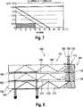
Mit Bezug auf
Im Unterschied zu den bisher beschriebenen optischen Systemen wird das Quellbild
Entsprechend der Aufteilung des Quellbildes
Beispielsweise ist die Aufteilung des Quellbildes derart getroffen, dass das erste Teilfeld
Das erste Teilfeld
Das zweite Teilfeld
Durch die Aufspaltung des Quellbildes
Während in dem gezeigten Ausführungsbeispiel das Quellbild
Das Konzept der Aufteilung des Quellbildes
Insgesamt ergeben sich dann bei einer Aufteilung des Quellbildes
Mit Bezug wieder auf
Das Auskoppelelement
Weiterhin ist die Beugungseffizienz des Auskoppelelements
Die Spektralbereiche und erforderlichen Gitterperioden hängen dabei von der Brechzahl des Lichtleiters
In dem in
Es ist jedoch ebenso möglich, anstelle von transmissiven Einkoppelelementen und transmissiven Auskoppelelementen reflektive Einkoppelelemente und/oder reflektive Auskoppelelemente vorzusehen, die dann entsprechend im Unterschied zu der in
Die vorstehend genannten Beugungsgitterstrukturen können sowohl im Falle transmissiver als auch im Falle reflektiver Beugungsgitterstrukturen als Blazegitter ausgebildet sein, oder trapezförmige oder rechteckige Stege aufweisen, die gegenüber der Gitterbasis geneigt sind.The abovementioned diffraction grating structures can be designed as blaze gratings both in the case of transmissive and in the case of reflective diffraction grating structures, or have trapezoidal or rectangular webs which are inclined relative to the grid base.
Die Aufteilung des Quellbildes
Eine andere Möglichkeit der Aufteilung des Quellbildes
Im Übrigen gilt die Beschreibung zu
Das optische System
Die Auskoppelanordnung
In
Insgesamt entsteht eine symmetrische Anordnung des optischen Systems
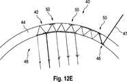
Die zuvor beschriebenen Lichtleiteranordnungen
Ausführungsbeispiele von optischen Systemen
Die Korrekturanordnung
In einem ersten Beispiel gemäß
In einem weiteren Beispiel gemäß
Die Korrekturanordnung
Aufgrund des Korrekturelements
Der vorstehend beschriebene Aspekt der vorliegenden Erfindung kann bei den Ausführungsbeispielen gemäß
Der vorliegende Aspekt kann jedoch auch unabhängig von den in Verbindung mit den
ZITATE ENTHALTEN IN DER BESCHREIBUNG QUOTES INCLUDE IN THE DESCRIPTION
Diese Liste der vom Anmelder aufgeführten Dokumente wurde automatisiert erzeugt und ist ausschließlich zur besseren Information des Lesers aufgenommen. Die Liste ist nicht Bestandteil der deutschen Patent- bzw. Gebrauchsmusteranmeldung. Das DPMA übernimmt keinerlei Haftung für etwaige Fehler oder Auslassungen.This list of the documents listed by the applicant has been generated automatically and is included solely for the better information of the reader. The list is not part of the German patent or utility model application. The DPMA assumes no liability for any errors or omissions.
Zitierte Nicht-PatentliteraturCited non-patent literature
- Artikel von Tapani Levola: "Diffractive optics for virtual reality displays", Journal of the SID 14/5, 2006, Seiten 467 bis 475[0003]Article by Tapani Levola: "Diffractive optics for virtual reality displays", Journal of the
SID 14/5, 2006, pages 467 to 475[0003] - Artikel von Tapani Levola: "Diffractive optics for virtual reality displays"[0081]Tapani Levola article: "Diffractive optics for virtual reality displays"[0081]
Claims (22)
Translated fromGermanPriority Applications (6)
| Application Number | Priority Date | Filing Date | Title |
|---|---|---|---|
| DE102015122055.5ADE102015122055B4 (en) | 2015-12-17 | 2015-12-17 | Optical system and method for transmitting a source image |
| EP16819486.8AEP3391122B1 (en) | 2015-12-17 | 2016-12-14 | Optical system and method for transmitting a source image |
| PCT/EP2016/080902WO2017102795A1 (en) | 2015-12-17 | 2016-12-14 | Optical system and method for transmitting a source image |
| ES16819486TES2866037T3 (en) | 2015-12-17 | 2016-12-14 | Optical system and procedure for transmitting a source image |
| US16/008,394US10191288B2 (en) | 2015-12-17 | 2018-06-14 | Optical system and method for transmitting a source image |
| US16/247,911US10394032B2 (en) | 2015-12-17 | 2019-01-15 | Optical system and method for transmitting a source image |
Applications Claiming Priority (1)
| Application Number | Priority Date | Filing Date | Title |
|---|---|---|---|
| DE102015122055.5ADE102015122055B4 (en) | 2015-12-17 | 2015-12-17 | Optical system and method for transmitting a source image |
Publications (2)
| Publication Number | Publication Date |
|---|---|
| DE102015122055A1true DE102015122055A1 (en) | 2017-06-22 |
| DE102015122055B4 DE102015122055B4 (en) | 2018-08-30 |
Family
ID=57680230
Family Applications (1)
| Application Number | Title | Priority Date | Filing Date |
|---|---|---|---|
| DE102015122055.5AActiveDE102015122055B4 (en) | 2015-12-17 | 2015-12-17 | Optical system and method for transmitting a source image |
Country Status (5)
| Country | Link |
|---|---|
| US (2) | US10191288B2 (en) |
| EP (1) | EP3391122B1 (en) |
| DE (1) | DE102015122055B4 (en) |
| ES (1) | ES2866037T3 (en) |
| WO (1) | WO2017102795A1 (en) |
Cited By (22)
| Publication number | Priority date | Publication date | Assignee | Title |
|---|---|---|---|---|
| DE102017119440A1 (en) | 2017-08-24 | 2019-02-28 | Carl Zeiss Ag | Curved light guide, imaging optics and HMD |
| WO2019120839A1 (en)* | 2017-12-18 | 2019-06-27 | Carl Zeiss Ag | Optical system for transmitting a source image |
| JP2020504326A (en)* | 2016-12-22 | 2020-02-06 | マジック リープ, インコーポレイテッドMagic Leap,Inc. | Color separation in waveguides using dichroic filters |
| CN110873962A (en)* | 2018-08-31 | 2020-03-10 | 成都理想境界科技有限公司 | Display system based on waveguide |
| CN111492301A (en)* | 2017-12-22 | 2020-08-04 | 迪斯帕列斯有限公司 | Multi-pupil waveguide display element and display device |
| CN111656253A (en)* | 2018-03-28 | 2020-09-11 | 迪斯帕列斯有限公司 | Waveguide Elements and Waveguide Stacks for Display Applications |
| JP2021508086A (en)* | 2017-12-22 | 2021-02-25 | ディスペリックス オサケ ユキチュア | Multi-layer waveguide display element |
| WO2021096651A1 (en)* | 2019-11-12 | 2021-05-20 | Facebook Technologies, Llc | High-index waveguide for conveying images with low period outcoupling grating |
| JP2021517264A (en)* | 2018-03-28 | 2021-07-15 | ディスペリックス オサケ ユキチュア | Waveguide display element |
| DE102020205405A1 (en) | 2020-04-29 | 2021-11-04 | Robert Bosch Gesellschaft mit beschränkter Haftung | Light guide device, projection device and method for projection |
| DE102020215386A1 (en) | 2020-08-06 | 2022-02-10 | Fraunhofer-Gesellschaft zur Förderung der angewandten Forschung eingetragener Verein | Path of light along an arc of a circle and transmission of a signal between two units rotating in relation to each other |
| JP2023050616A (en)* | 2021-09-30 | 2023-04-11 | セイコーエプソン株式会社 | virtual image display |
| US11825228B2 (en) | 2020-05-20 | 2023-11-21 | Meta Platforms Technologies, Llc | Programmable pixel array having multiple power domains |
| US11888002B2 (en) | 2018-12-17 | 2024-01-30 | Meta Platforms Technologies, Llc | Dynamically programmable image sensor |
| US11899252B2 (en) | 2020-08-06 | 2024-02-13 | Fraunhofer-Gesellschaft zur Förderung der angewandten Forschung e.V. | Light path along a circular arc and transmission of a signal between two units rotating relative to each other |
| US11948089B2 (en) | 2019-11-07 | 2024-04-02 | Meta Platforms Technologies, Llc | Sparse image sensing and processing |
| US11960638B2 (en) | 2019-10-30 | 2024-04-16 | Meta Platforms Technologies, Llc | Distributed sensor system |
| US11962928B2 (en) | 2018-12-17 | 2024-04-16 | Meta Platforms Technologies, Llc | Programmable pixel array |
| US12034015B2 (en) | 2018-05-25 | 2024-07-09 | Meta Platforms Technologies, Llc | Programmable pixel array |
| US12075175B1 (en) | 2020-09-08 | 2024-08-27 | Meta Platforms Technologies, Llc | Programmable smart sensor with adaptive readout |
| US12108141B2 (en) | 2019-08-05 | 2024-10-01 | Meta Platforms Technologies, Llc | Dynamically programmable image sensor |
| US12244936B2 (en) | 2022-01-26 | 2025-03-04 | Meta Platforms Technologies, Llc | On-sensor image processor utilizing contextual data |
Families Citing this family (131)
| Publication number | Priority date | Publication date | Assignee | Title |
|---|---|---|---|---|
| US9632226B2 (en) | 2015-02-12 | 2017-04-25 | Digilens Inc. | Waveguide grating device |
| EP3062142B1 (en) | 2015-02-26 | 2018-10-03 | Nokia Technologies OY | Apparatus for a near-eye display |
| NZ773836A (en) | 2015-03-16 | 2022-07-01 | Magic Leap Inc | Methods and systems for diagnosing and treating health ailments |
| EP3308220B1 (en) | 2015-06-15 | 2020-11-18 | Magic Leap, Inc. | Display system with optical elements for in-coupling multiplexed light streams |
| CN113759555B (en) | 2015-10-05 | 2024-09-20 | 迪吉伦斯公司 | Waveguide Display |
| DE102015122055B4 (en) | 2015-12-17 | 2018-08-30 | Carl Zeiss Ag | Optical system and method for transmitting a source image |
| FR3046850B1 (en) | 2016-01-15 | 2018-01-26 | Universite De Strasbourg | IMPROVED OPTICAL GUIDE AND OPTICAL SYSTEM COMPRISING SUCH AN OPTICAL GUIDE |
| JP6736911B2 (en)* | 2016-02-29 | 2020-08-05 | セイコーエプソン株式会社 | Luminous flux diameter expanding element and image display device |
| CN118112800A (en)* | 2016-03-01 | 2024-05-31 | 奇跃公司 | Reflective switching device for inputting light of different wavelengths into a waveguide |
| JP6923552B2 (en) | 2016-04-08 | 2021-08-18 | マジック リープ, インコーポレイテッドMagic Leap,Inc. | Augmented reality systems and methods with varifocal lens elements |
| US10481317B2 (en) | 2016-08-22 | 2019-11-19 | Magic Leap, Inc. | Nanograting method and apparatus |
| DE102016115938A1 (en)* | 2016-08-26 | 2018-03-01 | Carl Zeiss Jena Gmbh | Waveguides and devices for data input |
| JP2018054978A (en)* | 2016-09-30 | 2018-04-05 | セイコーエプソン株式会社 | Virtual image display device and manufacturing method thereof |
| EP3542213B1 (en) | 2016-11-18 | 2025-10-08 | Magic Leap, Inc. | Waveguide light multiplexer using crossed gratings |
| US11067860B2 (en) | 2016-11-18 | 2021-07-20 | Magic Leap, Inc. | Liquid crystal diffractive devices with nano-scale pattern and methods of manufacturing the same |
| CN115469458B (en) | 2016-11-18 | 2025-06-03 | 奇跃公司 | Spatially variable liquid crystal diffraction grating |
| KR102653578B1 (en)* | 2016-11-25 | 2024-04-04 | 엘지디스플레이 주식회사 | Electroluminescent display device integrated with image sensor |
| CN116107101A (en) | 2016-12-08 | 2023-05-12 | 奇跃公司 | Diffraction device based on cholesteric liquid crystal |
| US10895784B2 (en) | 2016-12-14 | 2021-01-19 | Magic Leap, Inc. | Patterning of liquid crystals using soft-imprint replication of surface alignment patterns |
| US10650552B2 (en) | 2016-12-29 | 2020-05-12 | Magic Leap, Inc. | Systems and methods for augmented reality |
| EP4300160A3 (en)* | 2016-12-30 | 2024-05-29 | Magic Leap, Inc. | Polychromatic light out-coupling apparatus, near-eye displays comprising the same, and method of out-coupling polychromatic light |
| US10409066B2 (en)* | 2017-01-19 | 2019-09-10 | Coretronic Corporation | Head-mounted display device with waveguide elements |
| JP2018114209A (en)* | 2017-01-20 | 2018-07-26 | 日機装株式会社 | Medical conduit |
| EP4250242A3 (en) | 2017-01-23 | 2023-11-29 | Magic Leap, Inc. | Eyepiece for virtual, augmented, or mixed reality systems |
| WO2018152235A1 (en)* | 2017-02-14 | 2018-08-23 | Optecks, Llc | Optical display system for augmented reality and virtual reality |
| IL311431A (en) | 2017-02-23 | 2024-05-01 | Magic Leap Inc | Display system with variable power reflector |
| EP3602175A4 (en) | 2017-03-21 | 2021-04-21 | Magic Leap, Inc. | EYE IMAGING DEVICE USING OPTICAL DIFFRACTION ELEMENTS |
| KR102699560B1 (en) | 2017-03-21 | 2024-08-27 | 매직 립, 인코포레이티드 | Stacked waveguides with different diffraction gratings for combined fields of view |
| KR102720048B1 (en)* | 2017-03-22 | 2024-10-18 | 매직 립, 인코포레이티드 | Wearable display device utilizing a composite field of view |
| CN108873326A (en) | 2017-05-16 | 2018-11-23 | 中强光电股份有限公司 | Head-mounted display device |
| US10578870B2 (en) | 2017-07-26 | 2020-03-03 | Magic Leap, Inc. | Exit pupil expander |
| US11698492B2 (en) | 2017-08-18 | 2023-07-11 | A9.Com, Inc. | Waveguide image combiners for augmented reality displays |
| US11668935B2 (en)* | 2017-08-18 | 2023-06-06 | A9.Com, Inc. | Waveguide image combiners for augmented reality displays |
| US11789265B2 (en) | 2017-08-18 | 2023-10-17 | A9.Com, Inc. | Waveguide image combiners for augmented reality displays |
| GB2566274A (en)* | 2017-09-06 | 2019-03-13 | Wave Optics Ltd | Display for use in an augmented reality or virtual reality device |
| EP3685215B1 (en) | 2017-09-21 | 2024-01-03 | Magic Leap, Inc. | Augmented reality display with waveguide configured to capture images of eye and/or environment |
| DE102017122353A1 (en) | 2017-09-26 | 2019-03-28 | Carl Zeiss Ag | Optical transmission device for transmitting a source image |
| US10534176B1 (en)* | 2017-10-09 | 2020-01-14 | Facebook Technologies, Llc | Waveguide display with gratings for improved diffraction efficiency |
| DE102017126908A1 (en) | 2017-11-15 | 2019-05-16 | Carl Zeiss Ag | Optical fiber for an HMD, HMD and method for transmitting an image in an HMD |
| KR102858869B1 (en) | 2017-12-10 | 2025-09-11 | 매직 립, 인코포레이티드 | Anti-reflective coatings on optical waveguides |
| US10852547B2 (en) | 2017-12-15 | 2020-12-01 | Magic Leap, Inc. | Eyepieces for augmented reality display system |
| CN111712751B (en) | 2017-12-20 | 2022-11-01 | 奇跃公司 | Insert for augmented reality viewing apparatus |
| CN109946907A (en) | 2017-12-20 | 2019-06-28 | 中强光电股份有限公司 | Projection device |
| CN108169842B (en)* | 2018-01-02 | 2020-06-26 | 京东方科技集团股份有限公司 | Waveguide assembly for smart display wearable device and smart display wearable device |
| US10942355B2 (en) | 2018-01-22 | 2021-03-09 | Facebook Technologies, Llc | Systems, devices, and methods for tiled multi-monochromatic displays |
| JP6880244B2 (en)* | 2018-01-25 | 2021-06-02 | 富士フイルム株式会社 | Projection image display material, windshield glass and head-up display system |
| CN108803022A (en)* | 2018-02-13 | 2018-11-13 | 成都理想境界科技有限公司 | Simple eye big visual field near-eye display device and the big visual field near-eye display device of binocular |
| US10755676B2 (en) | 2018-03-15 | 2020-08-25 | Magic Leap, Inc. | Image correction due to deformation of components of a viewing device |
| FI129359B (en)* | 2018-03-28 | 2021-12-31 | Dispelix Oy | Diffractive grating |
| EP4550031A3 (en)* | 2018-04-02 | 2025-07-16 | Magic Leap, Inc. | Waveguides with integrated optical elements |
| KR102752134B1 (en)* | 2018-05-14 | 2025-01-08 | 루머스 리미티드 | Projector configuration with sub-optical aperture for near-eye display and corresponding optical system |
| IL278511B2 (en)* | 2018-05-17 | 2025-01-01 | Lumus Ltd | Near-eye display having overlapping projector assemblies |
| JP7319303B2 (en) | 2018-05-31 | 2023-08-01 | マジック リープ, インコーポレイテッド | Radar head pose localization |
| US11579441B2 (en) | 2018-07-02 | 2023-02-14 | Magic Leap, Inc. | Pixel intensity modulation using modifying gain values |
| US11856479B2 (en) | 2018-07-03 | 2023-12-26 | Magic Leap, Inc. | Systems and methods for virtual and augmented reality along a route with markers |
| CN112585581B (en) | 2018-07-10 | 2024-10-18 | 奇跃公司 | Thread weaving for cross-ISA procedure calls |
| WO2020023266A1 (en)* | 2018-07-23 | 2020-01-30 | Magic Leap, Inc. | Systems and methods for external light management |
| CN119197613A (en) | 2018-07-24 | 2024-12-27 | 奇跃公司 | Temperature-dependent calibration of mobile detection equipment |
| CN116820239A (en) | 2018-08-03 | 2023-09-29 | 奇跃公司 | Fusion gesture based drift correction of fusion gestures for totem in a user interaction system |
| WO2020041615A1 (en) | 2018-08-22 | 2020-02-27 | Magic Leap, Inc. | Patient viewing system |
| WO2020047150A1 (en) | 2018-08-28 | 2020-03-05 | Magic Leap, Inc. | Dynamic incoupling gratings in imaging systems |
| US11454809B2 (en)* | 2018-10-16 | 2022-09-27 | Meta Platforms Technologies LLC | Display waveguide assembly with color cross-coupling |
| GB2578328A (en)* | 2018-10-24 | 2020-05-06 | Wave Optics Ltd | Device for augmented reality or virtual reality display |
| EP3884337A4 (en) | 2018-11-20 | 2022-08-17 | Magic Leap, Inc. | Eyepieces for augmented reality display system |
| DE102018220017B4 (en) | 2018-11-22 | 2021-07-22 | Robert Bosch Gmbh | Optical combination device and method for projecting an image and projection system with such a combination device |
| US11156832B1 (en)* | 2018-12-11 | 2021-10-26 | Rockwell Collins, Inc. | Systems and methods for multicolor display with large field of view |
| CN118409394A (en) | 2018-12-21 | 2024-07-30 | 奇跃公司 | Cavitation structures for promoting total internal reflection in waveguides |
| EP3881122A1 (en) | 2018-12-27 | 2021-09-22 | Nokia Technologies Oy | Apparatus, method, and system for use in a display |
| US20200225471A1 (en) | 2019-01-14 | 2020-07-16 | Digilens Inc. | Holographic Waveguide Display with Light Control Layer |
| JP7672980B2 (en)* | 2019-02-01 | 2025-05-08 | マジック リープ, インコーポレイテッド | Series-intercoupled optical elements |
| JP7396609B2 (en)* | 2019-02-14 | 2023-12-12 | 株式会社豊田中央研究所 | grating array |
| US20220283377A1 (en) | 2019-02-15 | 2022-09-08 | Digilens Inc. | Wide Angle Waveguide Display |
| CN109839746A (en)* | 2019-03-05 | 2019-06-04 | 京东方科技集团股份有限公司 | A kind of near-eye display device and preparation method thereof |
| GB201903037D0 (en)* | 2019-03-07 | 2019-04-24 | Wave Optics Ltd | Display for augmented realityor virtual reality |
| JP2022523852A (en) | 2019-03-12 | 2022-04-26 | マジック リープ, インコーポレイテッド | Aligning local content between first and second augmented reality viewers |
| WO2020223636A1 (en) | 2019-05-01 | 2020-11-05 | Magic Leap, Inc. | Content provisioning system and method |
| EP3980825A4 (en)* | 2019-06-07 | 2023-05-03 | Digilens Inc. | WAVEGUIDES WITH TRANSMITTING AND REFLECTING GRIDS AND RELATED MANUFACTURING PROCESSES |
| US11650423B2 (en) | 2019-06-20 | 2023-05-16 | Magic Leap, Inc. | Eyepieces for augmented reality display system |
| WO2020263834A1 (en)* | 2019-06-24 | 2020-12-30 | Magic Leap, Inc. | Customized polymer/glass diffractive waveguide stacks for augmented reality/mixed reality applications |
| CA3137994A1 (en) | 2019-06-27 | 2020-12-30 | Lumus Ltd | Apparatus and methods for eye tracking based on eye imaging via a light-guide optical element |
| WO2021021670A1 (en) | 2019-07-26 | 2021-02-04 | Magic Leap, Inc. | Systems and methods for augmented reality |
| CN110850669A (en)* | 2019-07-29 | 2020-02-28 | 上海鲲游光电科技有限公司 | Micro LED-based developing device and developing method thereof |
| CN110456508A (en)* | 2019-07-30 | 2019-11-15 | 成都理想境界科技有限公司 | A kind of near-eye display system and intelligent glasses |
| US20210055551A1 (en)* | 2019-08-23 | 2021-02-25 | Facebook Technologies, Llc | Dispersion compensation in volume bragg grating-based waveguide display |
| CN110515210B (en)* | 2019-09-03 | 2020-04-24 | 北京枭龙科技有限公司 | Grating waveguide device for near-to-eye display |
| JP7229385B2 (en)* | 2019-10-18 | 2023-02-27 | 富士フイルム株式会社 | image display device |
| JP7635230B2 (en) | 2019-11-14 | 2025-02-25 | マジック リープ, インコーポレイテッド | Systems and methods for virtual and augmented reality |
| CN114667538A (en) | 2019-11-15 | 2022-06-24 | 奇跃公司 | Viewing system for use in a surgical environment |
| TW202125039A (en)* | 2019-12-30 | 2021-07-01 | 宏碁股份有限公司 | Wearable display device |
| CN113495360A (en)* | 2020-03-20 | 2021-10-12 | 宏碁股份有限公司 | Wearable display device |
| JP7417937B2 (en)* | 2020-03-31 | 2024-01-19 | パナソニックIpマネジメント株式会社 | display device |
| KR20210127416A (en)* | 2020-04-14 | 2021-10-22 | 삼성전자주식회사 | Optical device with reduced chromatic aberration and display device including the same |
| CN115668033A (en) | 2020-05-22 | 2023-01-31 | 奇跃公司 | Method and system for dual-projector waveguide display with wide field of view |
| JP2021189379A (en)* | 2020-06-03 | 2021-12-13 | 株式会社日立エルジーデータストレージ | Video display device |
| CN114063283A (en)* | 2020-07-30 | 2022-02-18 | 舜宇光学(浙江)研究院有限公司 | Near-to-eye display optical device and method thereof |
| CN114114518A (en)* | 2020-08-28 | 2022-03-01 | 中强光电股份有限公司 | Optical waveguide, method for manufacturing optical waveguide, and head-mounted display device |
| CN114153067A (en)* | 2020-09-07 | 2022-03-08 | 华为技术有限公司 | A near-eye display device |
| WO2022053403A1 (en) | 2020-09-14 | 2022-03-17 | Saint-Gobain Glass France | Composite panel for a holographic head-up display |
| CN114531858A (en) | 2020-09-14 | 2022-05-24 | 法国圣戈班玻璃厂 | Method for producing a composite glass pane with a hologram |
| WO2022053548A1 (en) | 2020-09-14 | 2022-03-17 | Saint-Gobain Glass France | Method and apparatus for coating a curved pane with a photosensitive material |
| RU2753146C1 (en)* | 2020-09-22 | 2021-08-12 | Самсунг Электроникс Ко., Лтд. | Waveguide with holographic and diffraction optical elements, method for manufacture thereof, virtual and augmented reality apparatus containing such waveguide, and method for operation thereof |
| WO2022065658A1 (en)* | 2020-09-22 | 2022-03-31 | Samsung Electronics Co., Ltd. | Holographic waveguide, method of producing the same, and display device including the holographic waveguide |
| US11448815B2 (en)* | 2020-11-06 | 2022-09-20 | Meta Platforms Technologies LLC | Slab waveguide and projector with intermodal coupling |
| WO2022101194A1 (en) | 2020-11-11 | 2022-05-19 | Saint-Gobain Glass France | Laminated pane comprising a hologram element and an electrochromic functional element |
| WO2022150841A1 (en) | 2021-01-07 | 2022-07-14 | Digilens Inc. | Grating structures for color waveguides |
| EP4256395A4 (en)* | 2021-01-07 | 2024-10-16 | Vuzix Corporation | IMAGE LIGHT GUIDE WITH FLEXIBLE SUBSTRATE |
| WO2022163672A1 (en)* | 2021-01-29 | 2022-08-04 | 富士フイルム株式会社 | Image display device |
| CN113050281A (en)* | 2021-02-28 | 2021-06-29 | 南昌三极光电有限公司 | Optical system and mixed reality equipment |
| WO2022219873A1 (en)* | 2021-04-16 | 2022-10-20 | ソニーグループ株式会社 | Image display device and image display method |
| CN112904585B (en)* | 2021-04-21 | 2022-11-08 | 南昌三极光电有限公司 | Optical system |
| KR20240005001A (en)* | 2021-05-07 | 2024-01-11 | 어플라이드 머티어리얼스, 인코포레이티드 | Waveguide couplers with pass-through in-coupler grating |
| CN115373064A (en) | 2021-05-20 | 2022-11-22 | 中强光电股份有限公司 | Optical waveguide |
| KR102676604B1 (en)* | 2021-07-04 | 2024-06-18 | 루머스 리미티드 | Display with stacked light guiding elements providing different parts of the field of view |
| CN113534326B (en)* | 2021-07-19 | 2022-09-23 | 东南大学 | A polarization multiplexing high diffraction efficiency waveguide display device |
| US11619774B2 (en)* | 2021-07-22 | 2023-04-04 | Meta Platforms Technologies LLC | Talbot pattern illuminator and display based thereon |
| KR20230048902A (en)* | 2021-10-05 | 2023-04-12 | 주식회사 엘지화학 | Display apparatus |
| US12399369B2 (en)* | 2021-12-31 | 2025-08-26 | Meta Platforms Technologies, Llc | Curved light guide image combiner and system including the same |
| WO2023144085A1 (en) | 2022-01-26 | 2023-08-03 | Saint-Gobain Glass France | Composite pane with a hologram element and anti-reflective coating |
| CN116830047A (en) | 2022-01-26 | 2023-09-29 | 法国圣戈班玻璃厂 | Method for producing a composite glass pane having at least one hologram |
| US20230367046A1 (en)* | 2022-05-16 | 2023-11-16 | Rovi Guides, Inc. | Transparent conductive diffractive gratings for optical elements of augmented reality and virtual reality displays |
| US12393029B2 (en) | 2022-03-23 | 2025-08-19 | Adeia Guides Inc. | Buried diffractive gratings for optical elements of augmented reality and virtual reality head-mounted displays |
| CN118891570A (en)* | 2022-03-31 | 2024-11-01 | 松下知识产权经营株式会社 | Optical system and image display device |
| CN114755828B (en)* | 2022-04-20 | 2023-12-05 | 未来光学(上饶)科研院有限公司 | Large-view-field multi-waveguide system and near-eye display device |
| EP4544355A1 (en) | 2022-06-21 | 2025-04-30 | Saint-Gobain Glass France | Composite pane with hologram element and an optically high-refractive layer |
| EP4544356A1 (en) | 2022-06-21 | 2025-04-30 | Saint-Gobain Glass France | Composite pane with hologram element |
| CN118778253A (en)* | 2023-04-03 | 2024-10-15 | 苏州苏大维格科技集团股份有限公司 | Head-up display module and vehicle |
| KR102646815B1 (en)* | 2023-04-12 | 2024-03-13 | 주식회사 파노비젼 | Optical system of augmented reality glasses with saw tooth-type partial reflector array |
| WO2024245672A1 (en) | 2023-05-30 | 2024-12-05 | Saint-Gobain Glass France | Plate, device and method for the thermal stabilisation of a hologram element |
| WO2025058629A1 (en)* | 2023-09-14 | 2025-03-20 | Magic Leap, Inc. | Method and system for high order diffraction, large field of view augmented reality eyepiece waveguides |
| DE102023211189A1 (en)* | 2023-11-10 | 2025-05-15 | Carl Zeiss Jena Gmbh | High-resolution holocam through freeform exposure |
| CN118131388B (en)* | 2024-05-08 | 2024-08-23 | 南昌虚拟现实研究院股份有限公司 | AR display device adopting holographic optical waveguide |
Citations (4)
| Publication number | Priority date | Publication date | Assignee | Title |
|---|---|---|---|---|
| US20060221448A1 (en) | 2005-04-04 | 2006-10-05 | Mirage Innovations Ltd. | Multi-plane optical apparatus |
| US8233204B1 (en) | 2009-09-30 | 2012-07-31 | Rockwell Collins, Inc. | Optical displays |
| US20140140653A1 (en) | 2012-11-16 | 2014-05-22 | Rockwell Collins, Inc. | Transparent waveguide display |
| US20140218801A1 (en) | 2011-08-17 | 2014-08-07 | Bae Systems Plc | Projection display |
Family Cites Families (18)
| Publication number | Priority date | Publication date | Assignee | Title |
|---|---|---|---|---|
| US5369718A (en)* | 1991-10-15 | 1994-11-29 | The Furukawa Electric Co., Ltd. | Total internal reflection-type optical waveguide switch |
| JP2823470B2 (en)* | 1993-03-09 | 1998-11-11 | シャープ株式会社 | Optical scanning device, display device using the same, and image information input / output device |
| US5812714A (en)* | 1997-01-30 | 1998-09-22 | Cooper Industries, Inc. | Optical waveguide elements for a distributed lighting system |
| JPH11237517A (en)* | 1998-02-23 | 1999-08-31 | Fujitsu Ltd | Optical waveguide device |
| CA2253972C (en)* | 1998-05-29 | 2001-07-31 | Hitachi Cable, Ltd. | Optical wavelength multiplexer/demultiplexer |
| US6473209B1 (en)* | 1999-08-04 | 2002-10-29 | Digilens, Inc. | Apparatus for producing a three-dimensional image |
| US6270244B1 (en)* | 1999-11-16 | 2001-08-07 | Dn Labs Inc | Fiber optic illumination system having diffraction grating wavelength selector |
| AU2002251695A1 (en)* | 2000-12-15 | 2002-08-19 | Reflexite Corporation | Light redirecting film |
| US7418170B2 (en)* | 2004-03-29 | 2008-08-26 | Sony Corporation | Optical device and virtual image display device |
| EP1943556B1 (en)* | 2005-11-03 | 2009-02-11 | Mirage Innovations Ltd. | Binocular optical relay device |
| EP2174058A4 (en)* | 2007-05-01 | 2011-10-26 | Morgan Solar Inc | LIGHTING DEVICE |
| FR2948775B1 (en)* | 2009-07-31 | 2011-12-02 | Horiba Jobin Yvon Sas | PLANAR OPTICAL POLYCHROMATIC IMAGING SYSTEM WITH BROAD FIELD OF VISION |
| US8885995B2 (en)* | 2011-02-07 | 2014-11-11 | Morgan Solar Inc. | Light-guide solar energy concentrator |
| US8903207B1 (en)* | 2011-09-30 | 2014-12-02 | Rockwell Collins, Inc. | System for and method of extending vertical field of view in head up display utilizing a waveguide combiner |
| WO2016042283A1 (en)* | 2014-09-19 | 2016-03-24 | Milan Momcilo Popovich | Method and apparatus for generating input images for holographic waveguide displays |
| US9513480B2 (en)* | 2015-02-09 | 2016-12-06 | Microsoft Technology Licensing, Llc | Waveguide |
| DE102015122055B4 (en) | 2015-12-17 | 2018-08-30 | Carl Zeiss Ag | Optical system and method for transmitting a source image |
| US10545346B2 (en)* | 2017-01-05 | 2020-01-28 | Digilens Inc. | Wearable heads up displays |
- 2015
- 2015-12-17DEDE102015122055.5Apatent/DE102015122055B4/enactiveActive
- 2016
- 2016-12-14WOPCT/EP2016/080902patent/WO2017102795A1/ennot_activeCeased
- 2016-12-14ESES16819486Tpatent/ES2866037T3/enactiveActive
- 2016-12-14EPEP16819486.8Apatent/EP3391122B1/enactiveActive
- 2018
- 2018-06-14USUS16/008,394patent/US10191288B2/enactiveActive
- 2019
- 2019-01-15USUS16/247,911patent/US10394032B2/enactiveActive
Patent Citations (4)
| Publication number | Priority date | Publication date | Assignee | Title |
|---|---|---|---|---|
| US20060221448A1 (en) | 2005-04-04 | 2006-10-05 | Mirage Innovations Ltd. | Multi-plane optical apparatus |
| US8233204B1 (en) | 2009-09-30 | 2012-07-31 | Rockwell Collins, Inc. | Optical displays |
| US20140218801A1 (en) | 2011-08-17 | 2014-08-07 | Bae Systems Plc | Projection display |
| US20140140653A1 (en) | 2012-11-16 | 2014-05-22 | Rockwell Collins, Inc. | Transparent waveguide display |
Cited By (34)
| Publication number | Priority date | Publication date | Assignee | Title |
|---|---|---|---|---|
| US11249255B2 (en) | 2016-12-22 | 2022-02-15 | Magic Leap, Inc. | Color separation in planar waveguides using an optical filter between two diffractive optical elements (DOE) |
| JP2020504326A (en)* | 2016-12-22 | 2020-02-06 | マジック リープ, インコーポレイテッドMagic Leap,Inc. | Color separation in waveguides using dichroic filters |
| JP7039598B2 (en) | 2016-12-22 | 2022-03-22 | マジック リープ, インコーポレイテッド | Color separation in waveguides using dichroic filters |
| WO2019038374A1 (en) | 2017-08-24 | 2019-02-28 | Carl Zeiss Ag | CURVED LIGHT GUIDE, PICTURE OPTICS AND HMD |
| DE102017119440A1 (en) | 2017-08-24 | 2019-02-28 | Carl Zeiss Ag | Curved light guide, imaging optics and HMD |
| WO2019120839A1 (en)* | 2017-12-18 | 2019-06-27 | Carl Zeiss Ag | Optical system for transmitting a source image |
| US11693241B2 (en) | 2017-12-18 | 2023-07-04 | tooz technologies GmbH | Optical system for transmitting a source image |
| CN111527441B (en)* | 2017-12-18 | 2022-08-26 | 图茨技术股份有限公司 | Optical system for transmitting source images |
| CN111527441A (en)* | 2017-12-18 | 2020-08-11 | 图茨技术股份有限公司 | Optical system for transmitting source images |
| US11366317B2 (en) | 2017-12-22 | 2022-06-21 | Dispelix Oy | Multipupil waveguide display element and display device |
| JP2021508086A (en)* | 2017-12-22 | 2021-02-25 | ディスペリックス オサケ ユキチュア | Multi-layer waveguide display element |
| JP7308205B2 (en) | 2017-12-22 | 2023-07-13 | ディスペリックス オサケ ユキチュア | multilayer waveguide display element |
| CN111492301A (en)* | 2017-12-22 | 2020-08-04 | 迪斯帕列斯有限公司 | Multi-pupil waveguide display element and display device |
| JP7328235B2 (en) | 2018-03-28 | 2023-08-16 | ディスペリックス オサケ ユキチュア | waveguide display element |
| CN111656253B (en)* | 2018-03-28 | 2023-11-17 | 迪斯帕列斯有限公司 | Waveguide element and waveguide stack for display applications |
| CN111656253A (en)* | 2018-03-28 | 2020-09-11 | 迪斯帕列斯有限公司 | Waveguide Elements and Waveguide Stacks for Display Applications |
| JP2021517264A (en)* | 2018-03-28 | 2021-07-15 | ディスペリックス オサケ ユキチュア | Waveguide display element |
| US12034015B2 (en) | 2018-05-25 | 2024-07-09 | Meta Platforms Technologies, Llc | Programmable pixel array |
| CN110873962A (en)* | 2018-08-31 | 2020-03-10 | 成都理想境界科技有限公司 | Display system based on waveguide |
| CN110873962B (en)* | 2018-08-31 | 2022-05-20 | 成都理想境界科技有限公司 | Display system based on waveguide |
| US11888002B2 (en) | 2018-12-17 | 2024-01-30 | Meta Platforms Technologies, Llc | Dynamically programmable image sensor |
| US11962928B2 (en) | 2018-12-17 | 2024-04-16 | Meta Platforms Technologies, Llc | Programmable pixel array |
| US12108141B2 (en) | 2019-08-05 | 2024-10-01 | Meta Platforms Technologies, Llc | Dynamically programmable image sensor |
| US11960638B2 (en) | 2019-10-30 | 2024-04-16 | Meta Platforms Technologies, Llc | Distributed sensor system |
| US11948089B2 (en) | 2019-11-07 | 2024-04-02 | Meta Platforms Technologies, Llc | Sparse image sensing and processing |
| CN114730091A (en)* | 2019-11-12 | 2022-07-08 | 脸谱科技有限责任公司 | High-index waveguides for image transfer with low-period outcoupling gratings |
| WO2021096651A1 (en)* | 2019-11-12 | 2021-05-20 | Facebook Technologies, Llc | High-index waveguide for conveying images with low period outcoupling grating |
| DE102020205405A1 (en) | 2020-04-29 | 2021-11-04 | Robert Bosch Gesellschaft mit beschränkter Haftung | Light guide device, projection device and method for projection |
| US11825228B2 (en) | 2020-05-20 | 2023-11-21 | Meta Platforms Technologies, Llc | Programmable pixel array having multiple power domains |
| US11899252B2 (en) | 2020-08-06 | 2024-02-13 | Fraunhofer-Gesellschaft zur Förderung der angewandten Forschung e.V. | Light path along a circular arc and transmission of a signal between two units rotating relative to each other |
| DE102020215386A1 (en) | 2020-08-06 | 2022-02-10 | Fraunhofer-Gesellschaft zur Förderung der angewandten Forschung eingetragener Verein | Path of light along an arc of a circle and transmission of a signal between two units rotating in relation to each other |
| US12075175B1 (en) | 2020-09-08 | 2024-08-27 | Meta Platforms Technologies, Llc | Programmable smart sensor with adaptive readout |
| JP2023050616A (en)* | 2021-09-30 | 2023-04-11 | セイコーエプソン株式会社 | virtual image display |
| US12244936B2 (en) | 2022-01-26 | 2025-03-04 | Meta Platforms Technologies, Llc | On-sensor image processor utilizing contextual data |
Also Published As
| Publication number | Publication date |
|---|---|
| US20180299678A1 (en) | 2018-10-18 |
| US10394032B2 (en) | 2019-08-27 |
| WO2017102795A1 (en) | 2017-06-22 |
| DE102015122055B4 (en) | 2018-08-30 |
| EP3391122A1 (en) | 2018-10-24 |
| US20190155034A1 (en) | 2019-05-23 |
| EP3391122B1 (en) | 2021-03-03 |
| ES2866037T3 (en) | 2021-10-19 |
| US10191288B2 (en) | 2019-01-29 |
Similar Documents
| Publication | Publication Date | Title |
|---|---|---|
| DE102015122055B4 (en) | Optical system and method for transmitting a source image | |
| EP3504580B1 (en) | Waveguide and head up display device | |
| DE602004009258T2 (en) | Optical devices, in particular for remote sensing | |
| EP3710878B1 (en) | Light guide for an hmd, hmd and method for transmitting an image in an hmd | |
| EP3729170B1 (en) | Optical system for transmitting a source image | |
| DE69128401T2 (en) | Optical display device | |
| WO2008135110A2 (en) | Display unit, and displaying method for the binocular representation of a multicolor image | |
| WO2019012028A1 (en) | DISPLAY DEVICE FOR MAGNIFYING THE VISIBILITY | |
| EP3673316B1 (en) | Curved light guide, imaging optical unit and hmd | |
| DE202016106927U1 (en) | Transparent curved eyepiece with structured optics combiner | |
| EP2498106B1 (en) | Optical observation device with at least one visual observation beam | |
| EP4270089A2 (en) | Spectacles glass suitable to be placed on the head of a user and a display device generating an image and also a display device for such a spectacles glass | |
| EP3210068B1 (en) | Imaging optical unit and smart glasses | |
| EP3807695B1 (en) | Optical waveguide for a display device | |
| WO2019063291A1 (en) | OPTICAL TRANSMISSION ARRANGEMENT FOR TRANSMITTING A SOURCE IMAGE | |
| DE102008020858B4 (en) | Projection system for an optical display device and head-mounted display with such | |
| WO2022268751A1 (en) | Optical assembly and head-up display havng a plurality of image planes | |
| DE102007011561A1 (en) | Correcting device for adjusting wavelength dependence in diffraction-based optical systems has a diffractive optical light modulator with controllable structures and a source of light for illuminating the light modulator | |
| DE102020121647A1 (en) | Waveguide display arrangement for a 3D head-up display device in a vehicle and method for its operation | |
| DE102023132012B4 (en) | IMAGE PROJECTION DEVICE FOR POLYCHROMATIC PROJECTION OF AN IMAGE INTO AN OBSERVATION FIELD | |
| DE102007036974A1 (en) | HMD device | |
| DE102023107977A1 (en) | display device | |
| DE102019102586A1 (en) | Light guide arrangement, imaging optics, head-mounted display and method for improving the imaging quality of an imaging optics | |
| DE102023128381A1 (en) | Light field display and method for generating an image using |
Legal Events
| Date | Code | Title | Description |
|---|---|---|---|
| R012 | Request for examination validly filed | ||
| R079 | Amendment of ipc main class | Free format text:PREVIOUS MAIN CLASS: G02B0027010000 Ipc:G02B0027100000 | |
| R016 | Response to examination communication | ||
| R016 | Response to examination communication | ||
| R018 | Grant decision by examination section/examining division | ||
| R020 | Patent grant now final |