DE102015121817A1 - Stretchable electrode - Google Patents
Stretchable electrodeDownload PDFInfo
- Publication number
- DE102015121817A1 DE102015121817A1DE102015121817.8ADE102015121817ADE102015121817A1DE 102015121817 A1DE102015121817 A1DE 102015121817A1DE 102015121817 ADE102015121817 ADE 102015121817ADE 102015121817 A1DE102015121817 A1DE 102015121817A1
- Authority
- DE
- Germany
- Prior art keywords
- connecting portion
- electrode
- section
- contact
- implantable electrode
- Prior art date
- Legal status (The legal status is an assumption and is not a legal conclusion. Google has not performed a legal analysis and makes no representation as to the accuracy of the status listed.)
- Withdrawn
Links
- 238000000034methodMethods0.000claimsdescription30
- 238000004804windingMethods0.000claimsdescription10
- IHQKEDIOMGYHEB-UHFFFAOYSA-Msodium dimethylarsinateChemical class[Na+].C[As](C)([O-])=OIHQKEDIOMGYHEB-UHFFFAOYSA-M0.000claims1
- 239000011888foilSubstances0.000description16
- 238000004519manufacturing processMethods0.000description9
- 239000011265semifinished productSubstances0.000description9
- 238000010438heat treatmentMethods0.000description5
- 210000001519tissueAnatomy0.000description5
- 239000013598vectorSubstances0.000description5
- 229920000106Liquid crystal polymerPolymers0.000description4
- 239000004977Liquid-crystal polymers (LCPs)Substances0.000description4
- 238000005452bendingMethods0.000description4
- 238000002513implantationMethods0.000description4
- 229920001169thermoplasticPolymers0.000description4
- 239000011248coating agentSubstances0.000description3
- 238000000576coating methodMethods0.000description3
- 239000000463materialSubstances0.000description3
- 229910001020Au alloyInorganic materials0.000description2
- 238000010276constructionMethods0.000description2
- 238000001816coolingMethods0.000description2
- PCHJSUWPFVWCPO-UHFFFAOYSA-NgoldChemical compound[Au]PCHJSUWPFVWCPO-UHFFFAOYSA-N0.000description2
- 239000010931goldSubstances0.000description2
- 229910052737goldInorganic materials0.000description2
- 239000003353gold alloySubstances0.000description2
- 210000000663muscle cellAnatomy0.000description2
- 239000004033plasticSubstances0.000description2
- 229920003023plasticPolymers0.000description2
- 229920000642polymerPolymers0.000description2
- 239000002243precursorSubstances0.000description2
- 238000007493shaping processMethods0.000description2
- 238000007669thermal treatmentMethods0.000description2
- 229910000566Platinum-iridium alloyInorganic materials0.000description1
- 239000004809TeflonSubstances0.000description1
- 229920006362Teflon®Polymers0.000description1
- 239000000654additiveSubstances0.000description1
- 230000000996additive effectEffects0.000description1
- 239000000853adhesiveSubstances0.000description1
- 230000001070adhesive effectEffects0.000description1
- 230000015572biosynthetic processEffects0.000description1
- 230000000747cardiac effectEffects0.000description1
- 239000000919ceramicSubstances0.000description1
- 150000001875compoundsChemical class0.000description1
- 239000004020conductorSubstances0.000description1
- 230000004927fusionEffects0.000description1
- 239000011521glassSubstances0.000description1
- 239000007943implantSubstances0.000description1
- 210000001640nerve endingAnatomy0.000description1
- 230000007383nerve stimulationEffects0.000description1
- 210000002569neuronAnatomy0.000description1
- HWLDNSXPUQTBOD-UHFFFAOYSA-Nplatinum-iridium alloyChemical class[Ir].[Pt]HWLDNSXPUQTBOD-UHFFFAOYSA-N0.000description1
- 239000002861polymer materialSubstances0.000description1
- 229920001296polysiloxanePolymers0.000description1
- 229920002635polyurethanePolymers0.000description1
- 239000004814polyurethaneSubstances0.000description1
- 238000004382pottingMethods0.000description1
- 230000037303wrinklesEffects0.000description1
Images


Classifications
- A—HUMAN NECESSITIES
- A61—MEDICAL OR VETERINARY SCIENCE; HYGIENE
- A61N—ELECTROTHERAPY; MAGNETOTHERAPY; RADIATION THERAPY; ULTRASOUND THERAPY
- A61N1/00—Electrotherapy; Circuits therefor
- A61N1/02—Details
- A61N1/04—Electrodes
- A61N1/05—Electrodes for implantation or insertion into the body, e.g. heart electrode
- A61N1/0551—Spinal or peripheral nerve electrodes
Landscapes
- Health & Medical Sciences (AREA)
- Cardiology (AREA)
- Heart & Thoracic Surgery (AREA)
- Engineering & Computer Science (AREA)
- Biomedical Technology (AREA)
- Nuclear Medicine, Radiotherapy & Molecular Imaging (AREA)
- Radiology & Medical Imaging (AREA)
- Life Sciences & Earth Sciences (AREA)
- Animal Behavior & Ethology (AREA)
- General Health & Medical Sciences (AREA)
- Public Health (AREA)
- Veterinary Medicine (AREA)
- Electrotherapy Devices (AREA)
Abstract
Translated fromGermanDescription
Translated fromGermanDie Erfindung betrifft eine implantierbare Elektrode mit einem Kontaktelement zur Kontaktierung von Körpergewebe, beispielweise Muskelzellen des Herzens oder Nervenenden, und mit einem Verbindungsabschnitt zur Verbindung eines medizinischen Geräts, etwa ein Schrittmacher, mit dem Kontaktelement. Ferner betrifft die Erfindung ein Verfahren zum Herstellen einer implantierbaren Elektrode mit einem Kontaktelement zur Kontaktierung von Körpergewebe, und mit einem Verbindungsabschnitt zur Verbindung eines medizinischen Geräts mit dem Kontaktelement.The invention relates to an implantable electrode having a contact element for contacting body tissue, for example muscle cells of the heart or nerve endings, and having a connection section for connecting a medical device, such as a pacemaker, to the contact element. Furthermore, the invention relates to a method for producing an implantable electrode with a contact element for contacting body tissue, and with a connecting portion for connecting a medical device to the contact element.
Implantierbare Elektroden und Verfahren zu deren Herstellung sind allgemein bekannt. Quer zu ihrer Längsachse sind implantierbare Elektroden oftmals flexibel und leicht biegbar. Entlang der Längsachse sind die Elektroden jedoch im Wesentlichen nicht dehnbar, wobei bekannte Elektroden entlang der Längsachse beispielsweise weniger als 1 % dehnbar sind.Implantable electrodes and methods for their production are well known. Implantable electrodes are often flexible and easily bendable transverse to their longitudinal axis. However, along the longitudinal axis, the electrodes are substantially non-extensible, with known electrodes being stretchable along the longitudinal axis, for example, less than 1%.
Der Erfindung liegt daher die Aufgabe zugrunde, eine implantierbare Elektrode und ein Verfahren zum Herstellen einer implantierbaren Elektrode bereit zu stellen, wobei die implantierbare Elektrode entlang ihrer Längsachse zumindest abschnittsweise dehnbar ist.The invention is therefore based on the object to provide an implantable electrode and a method for producing an implantable electrode, wherein the implantable electrode is at least partially stretchable along its longitudinal axis.
Für die eingangs genannte Elektrode ist die Aufgabe dadurch gelöst, dass sich der Verbindungsabschnitt zumindest teilweise um die Längsachse der Elektrode herum windet. Für das eingangs genannte Verfahren ist die Aufgabe dadurch gelöst, dass der Verbindungsabschnitt zumindest teilweise um eine Achse herum gewunden wird. Dadurch, dass der Verbindungsabschnitt zumindest teilweise gewunden ausgeformt ist, läßt sich die Elektrode und insbesondere deren Verbindungsabschnitt einfach entlang der Längsachse dehnen, also auseinander ziehen, selbst wenn der Verbindungsabschnitt an sich nicht elastisch dehnbar ist.For the above-mentioned electrode, the object is achieved in that the connecting portion at least partially winds around the longitudinal axis of the electrode. For the aforementioned method, the object is achieved in that the connecting portion is at least partially wound around an axis. Characterized in that the connecting portion is formed at least partially wound, the electrode and in particular the connecting portion can easily stretch along the longitudinal axis, so pull apart, even if the connecting portion is not elastically extensible per se.
Die erfindungsgemäße Lösung kann durch verschiedene, jeweils für sich vorteilhafte, und, sofern nicht anders ausgeführt, beliebig miteinander kombinierbare Ausgestaltungen weiter verbessert werden. Auf diese Ausgestaltungsformen und die mit ihnen verbundenen Vorteilen ist im Folgenden eingegangen.The solution according to the invention can be further improved by various configurations which are advantageous in each case and, if not stated otherwise, can be combined with one another as desired. These embodiments and the advantages associated with them are discussed below.
So kann der Verbindungsabschnitt mindestens eine Teilwindung, wenigstens eine ganze Windung oder mehr als eine Windung aufweisen. Je mehr Windungen der Verbindungsabschnitt aufweist, desto leichter lässt sich der Verbindungsabschnitt entlang der Längsachse auseinander ziehen. Ferner lässt sich mit steigender Windungsanzahl auch die maximal mögliche Verlängerung des Verbindungsabschnitts entlang der Längsachse vergrößern.Thus, the connecting portion may have at least one partial turn, at least one complete turn or more than one turn. The more turns the connecting section has, the easier it is for the connecting section to pull apart along the longitudinal axis. Furthermore, as the number of turns increases, the maximum possible extension of the connecting section along the longitudinal axis can be increased.
Beispielsweise ist der Verbindungsabschnitt zumindest abschnittsweise helixförmig ausgebildet. Die Helix ist eine vergleichsweise regelmäßige Struktur, die sich einfach herstellen lässt.For example, the connecting portion is at least partially helical. The helix is a comparatively regular structure that is easy to manufacture.
Eine den gewundenen Teil des Verbindungsabschnitts umhüllende Form kann im Wesentlichen einem Zylinder entsprechen, wenn die Längsachse gerade verläuft und die Elektrode nicht quer zur Längsachse gebogen ist. Ist die Elektrode gebogen, kann die umhüllende Form einem Schlauch entsprechen. Durch die im Wesentlichen zylindrisch oder schlauchartig ausgeformte Umhüllende ragen keine Teile des Verbindungsabschnitts über andere Teile des Verbindungsabschnitts hervor, sodass der Verbindungsabschnitt einfach implantierbar ist.A form enveloping the tortuous portion of the connecting portion may substantially correspond to a cylinder when the longitudinal axis is straight and the electrode is not bent transversely to the longitudinal axis. If the electrode is bent, the enveloping shape may correspond to a tube. As a result of the substantially cylindrical or tubular shaped envelope, no parts of the connecting portion project beyond other parts of the connecting portion, so that the connecting portion is simply implantable.
Der Verbindungsabschnitt kann als ein um die Längsachse herum gewundenes flaches Band ausgeformt sein. Das flache Band kann ferner das mindestens eine Kontaktelement tragenden Kontaktabschnitt der Elektrode ausformen. Ein flaches Band lässt sich einfacher winden als beispielsweise ein rundes Kabel, das womöglich auf einer Innenseite der Windung Falten bilden kann.The connecting portion may be formed as a flat band wound around the longitudinal axis. The flat band may further form the contact portion of the electrode carrying at least one contact member. A flat band is easier to wind than, for example, a round cable that can possibly form wrinkles on an inner side of the turn.
Gemäß einer Ausgestaltung des erfindungsgemäßen Verfahrens kann der Verbindungsabschnitt flächig ausgebildet und die zumindest eine Verbindungsleitung in einen flächigen Mantel eingebettet werden. Der flächige Mantel kann mit der zumindest einen eingebetteten Verbindungsleitung in die gewundene Form gebracht wird. Zum Beispiel kann der Mantel als ein Flachbandkabel ausgebildet werden, wobei die zumindest eine Verbindungsleitung zwischen zwei elektrisch isolierenden Folien, insbesondere thermoplastische Polymerfolien, zum Beispiel aus einem Flüssigkristall-Polymer, angeordnet wird. Insbesondere kann eine der Folien auf einer ihrer Seiten mit der zumindest einen Verbindungsleitung versehen werden. Auf der der Verbindungsleitung gegenüberliegenden Seite dieser Folie kann die Folie mit dem wenigstens einen Kontaktelement versehen sein oder werden. Die Verbindungsleitung und/oder das Kontaktelement können additiv oder subtraktiv auf die Folie aufgebracht werden. Um die Verbindungsleitung und das Kontaktelement miteinander in Verbindung bringen zu können, kann eine Durchkontaktierung vorgesehen werden, die als ein sogenanntes metallisiertes Via ausgebildet sein kann. Ein Via ist beispielsweise eine die beiden Seiten der Folie miteinander verbindende metallisierte Öffnung in der Folie.According to one embodiment of the method according to the invention, the connecting portion can be formed flat and the at least one connecting line can be embedded in a flat jacket. The flat jacket can be brought into the tortuous shape with the at least one embedded connecting line. For example, the sheath can be formed as a ribbon cable, wherein the at least one connecting line between two electrically insulating films, in particular thermoplastic polymer films, for example, from a liquid crystal polymer, is arranged. In particular, one of the foils on one of its sides can be provided with the at least one connecting line. On the opposite side of the connecting line of this film, the film may be provided with the at least one contact element or be. The connecting line and / or the contact element can be applied additively or subtractive to the film. In order to be able to connect the connecting line and the contact element to one another, a plated-through hole can be provided, which can be designed as a so-called metallized via. A via is, for example, a metallized opening in the film connecting the two sides of the film.
Der Verbindungsabschnitt und insbesondere dessen gewundener flächiger Mantel kann breite und schmale Seiten aufweisen, wobei eine der breiten Seiten eine von der Längsachse weg weisende Außenseite ist. Die Außenseite ist vorzugsweise flach und ermöglicht, dass insbesondere der gewundene Teil des Verbindungsabschnitts bei der Implantation einfach an Gewebe anliegend gleiten kann, ohne mit diesem zu verhaken. Diese Elektrode ist also einfach implantierbar.The connecting portion and in particular its winding flat jacket can have wide and narrow sides, wherein one of the wide Pages is an outer side facing away from the longitudinal axis. The outside is preferably flat, and in particular allows the tortuous part of the connecting portion to easily slide against tissue without being caught during implantation. This electrode is therefore easy to implant.
Um die Windung dauerhaft bereitstellen zu können, kann die Außenseite größer sein als eine der Längsachse zugewandte Innenseite des Verbindungsabschnitts und insbesondere des gewundenen flächigen Mantels.In order to be able to provide the turn permanently, the outer side can be larger than an inner side of the connecting section facing the longitudinal axis and in particular of the wound flat jacket.
Die Außenseite kann stärker plastisch verformt und beispielsweise gestreckt sein als die Innenseite. Die stärkere Streckung der Außenseite lässt sich einfach mechanisch erzeugen.The outside can be more plastically deformed and, for example, stretched than the inside. The stronger stretch of the outside can be easily generated mechanically.
Die Außenseite kann mechanisch gedehnt und dabei thermisch behandelt worden sein, um die größere Außenseite zu erzeugen. Die Kombination aus mechanischer Dehnung oder Streckung und thermischer Behandlung ermöglicht die Vergrößerung und beispielsweise plastische Dehnung der Außenseite bei geringen mechanischen Kräften, sodass eine Beschädigung der Elektrode vermieden und Produktionsausschuss verringert wird.The outside may have been mechanically stretched and thermally treated to create the larger exterior. The combination of mechanical stretching or stretching and thermal treatment enables the enlargement and, for example, plastic expansion of the outside with low mechanical forces, so that damage to the electrode is avoided and production scrap is reduced.
Alternativ oder zusätzlich zur vergrößerten Ausbildung der Außenseite kann der Verbindungsabschnitt und insbesondere dessen gewundener flächiger Mantel mit einer eine mechanischen Spannung auf den Verbindungsabschnitt ausübenden Schicht versehen sein, um die Windung zu erzeugen. Ist die Schicht auf der Außenseite des gewundenen Verbindungsabschnitts aufgetragen, so kann die Schicht ausgebildet sein, eine Druckspannung zu erzeugen. Eine auf die Innenseite des gewundenen Verbindungsabschnitts aufgebrachte Schicht kann ausgebildet sein, eine Zugspannung zu erzeugen. Die Außenseite und/oder die Innenseite können jeweils mit einer Schicht versehen sein.As an alternative or in addition to the enlarged outer side configuration, the connecting section, and in particular its coiled flat jacket, can be provided with a layer which exerts a mechanical stress on the connecting section in order to produce the winding. When the layer is applied on the outside of the wound connection portion, the layer may be formed to generate a compressive stress. A layer applied to the inside of the wound connection portion may be configured to generate a tensile stress. The outside and / or the inside can each be provided with a layer.
Der Kontaktabschnitt kann ungewunden ausgeformt sein und in einem unverformten Zustand, in dem er beispielsweise auf einer ebenen Fläche liegt, im Wesentlichen eben ausgebildet sein.The contact portion may be formed without shape and formed in an undeformed state in which it is, for example, on a flat surface, substantially flat.
Gemäß einer Ausgestaltung des erfindungsgemäßen Verfahrens kann der Verbindungsabschnitt um eine zylindrische Form, beispielsweise ein zylindrischer Kern, herum gewunden werden. In der gewundenen Form können einzelne oder alle Windungen an wenigstens einer Nachbarwindung befestigt sein, um die gewundene Form dauerhaft beizubehalten. Ferner können einzelne oder alle Windungen am Kern befestigt sein. Um die Elektrode und insbesondere deren Verbindungsabschnitt mit einem Kern, der an den Windungen fixiert ist, in die Länge ziehen zu können, kann der Kern entlang der Längsachse der Elektrode flexibel sein. Alternativ kann der Kern als ein Werkzeug dienen, um das der Verbindungsabschnitt und insbesondere dessen Mantel herum gewunden wird, wobei der Kern aus dem gewundenen Teil des Verbindungsabschnitts entfernt wird, nachdem der gewundene Teil ausgebildet wurde.According to one embodiment of the method according to the invention, the connecting portion can be wound around a cylindrical shape, for example a cylindrical core. In the tortuous form, single or all turns may be attached to at least one adjacent turn to permanently maintain the tortuous shape. Furthermore, individual or all windings can be fastened to the core. In order to be able to lengthen the electrode and in particular its connecting portion with a core which is fixed to the windings, the core can be flexible along the longitudinal axis of the electrode. Alternatively, the core may serve as a tool around which the connecting portion, and in particular its sheath, is wound, with the core being removed from the coiled portion of the connecting portion after the coiled portion has been formed.
Vorzugsweise ist der Kern zylindrisch oder hohlzylindrisch und beispielsweise schlauchförmig ausgebildet. Der Kern kann verhindern, dass der Mantel bei einem womöglich zu starkem Biegen, also bei einem zu kleinen Biegeradius, einknickt und entstehende Knickkanten oder -ecken die Implantation der Elektrode erschweren.Preferably, the core is cylindrical or hollow cylindrical and, for example, tubular. The core can prevent the jacket from buckling in the event of too much bending, that is to say with a bending radius which is too small, and resulting bending edges or corners make the implantation of the electrode more difficult.
Der Mantel kann stoffschlüssig und zum Beispiel durch Verschmelzen mit dem Kern verbunden sein, wodurch die Verbindung zwischen Mantel und Kern ohne weitere Hilfsmittel, beispielsweise Kleber oder Nähte, ausgebildet sein kann.The jacket may be materially bonded and, for example, by fusion with the core, whereby the connection between the shell and core without further aids, such as adhesive or seams may be formed.
Der Kern kann mit einem sich entlang der Längsachse der Elektrode durchgängig durch den Kern erstreckenden Lumen ausgebildet sein, damit die Elektrode beispielsweise mit Hilfe eines Führungsdrahtes, der die Elektrode bei der Implantation führt, implantierbar ist. Ist die Elektrode ohne Kern ausgebildet, kann der gewundene Mantel des Verbindungsabschnittes das Lumen bereitstellen.The core may be formed with a lumen extending continuously through the core along the longitudinal axis of the electrode to allow the electrode to be implanted, for example, by means of a guide wire guiding the electrode during implantation. If the electrode is formed without a core, the tortuous shell of the connecting portion can provide the lumen.
Das Material des Mantels kann ein thermoplastisches Polymer, beispielsweise ein Flüssigkristall-Polymer sein. Der Kern kann beispielsweise aus Glas oder ebenfalls aus einem Polymer, zum Beispiel aus einem Flüssigkristall-Polymer, gefertigt sein und sogar daraus bestehen. Die Verbindungsleitung besteht zum Beispiel aus Gold oder aus einer Goldlegierung. Das zumindest eine Kontaktelement kann aus Gold, aus einer Goldlegierung oder zum Beispiel aus einer Platin-Iridium-Legierung gefertigt sein.The material of the shell may be a thermoplastic polymer, for example a liquid crystal polymer. The core may for example be made of glass or also of a polymer, for example of a liquid crystal polymer, and even consist thereof. The connecting line consists for example of gold or a gold alloy. The at least one contact element may be made of gold, of a gold alloy or for example of a platinum-iridium alloy.
Die Folie kann mit dem zumindest einen Kontaktelement und der mindestens einen Verbindungsleitung um den Kern herum gelegt werden. Alternativ oder zusätzlich kann eine weitere Folie auf die Seite der Folie, die die Verbindungsleitung aufweist, aufgelegt werden. Insbesondere wenn die Folien thermoplastische Polymerfolien sind, können die beiden Folien thermisch dauerhaft miteinander verbunden und beispielsweise verschmolzen werden.The foil can be placed around the core with the at least one contact element and the at least one connecting line. Alternatively or additionally, another film may be placed on the side of the film which has the connecting line. In particular, when the films are thermoplastic polymer films, the two films can be thermally permanently connected to each other and, for example, fused.
Um den Mantel mithilfe des Kerns winden zu können, kann der Mantel zunächst um den Kern herumgelegt werden, wobei der Mantel sich insbesondere entlang der Umfangsrichtung des Kerns an diesen anschmiegen und diesen zumindest teilweise oder sogar vollständig umgeben kann.In order to be able to wind the sheath with the aid of the core, the sheath can first be wrapped around the core, whereby the sheath can conform to the core along the circumferential direction of the core and surround it at least partially or even completely.
Soll der Mantel einfach am Kern befestigt werden, können der Mantel und der Kern stoffschlüssig miteinander verbunden werden. Insbesondere wenn sowohl das Mantelmaterial als auch der Kern aus einem thermoplastischen Polymermaterial gefertigt sind, können der Mantel und der Kern unter Temperatur- und Druckeinwirkung einfach aneinander befestigt und zum Beispiel verschmolzen werden. Zum Beispiel kann der Mantel von einer Form gegen den Kern gedrückt werden, wobei die Form vorzugsweise nicht am Mantel haftet und beispielsweise Teflon- oder Keramikoberflächen aufweist, die den Mantel bei der Herstellung der Elektrode kontaktieren. Um den Mantel an dem Kern befestigen zu können, können Mantel und Kern auf bis zu 350°C und beispielsweise auf 200°C erwärmt werden. Diese Temperaturen können für bis zu 20 Minuten und beispielsweise fürs wenigstens 1 Sekunde aufrechterhalten werden. Das Material des Mantels und Kerns können bei einer derartigen Temperaturbehandlung miteinander verschmelzen und sich so nahtlos oder zumindest nahezu nahtlos stoffschlüssig miteinander verbinden. If the sheath is simply attached to the core, the sheath and the core can be materially connected to one another. In particular, when both the sheath material and the core are made of a thermoplastic polymer material, the sheath and the core can be easily attached to each other under temperature and pressure and, for example, be fused. For example, the shell may be pressed against the core by a mold, which mold preferably does not adhere to the shell and, for example, has teflon or ceramic surfaces which contact the shell in the manufacture of the electrode. To be able to fasten the jacket to the core, the jacket and core can be heated up to 350 ° C and, for example, to 200 ° C. These temperatures can be maintained for up to 20 minutes, and for at least 1 second, for example. The material of the shell and core can merge with each other during such a temperature treatment and thus connect seamlessly or at least almost seamlessly with each other.
Beispielsweise kann als Flüssigkristall-Polymer Polyurethan oder ein anderes Polymer verwendet werden.For example, polyurethane or another polymer may be used as the liquid crystal polymer.
Im um die zylindrische Form und/oder den Kern gewundenen Zustand kann der gewundene Verbindungsabschnitt erwärmt werden. Beispielsweise kann diese Erwärmung oder Temperierung kurzzeitig sein und etwa eine 1 Sekunde betragen. Der Erwärmungsvorgang kann jedoch durchaus mehrere Minuten und beispielsweise bis zu 10 Minuten, bis zu 30 Minuten oder sogar bis zu 60 Minuten andauern. Temperaturen des gewundenen Verbindungsabschnitts können bei der thermischen Behandlung bis zu 150°C oder sogar bis zu 250°C oder sogar bis zu 350°C betragen.In the state wound around the cylindrical shape and / or the core, the coiled connection portion can be heated. For example, this heating or temperature control can be short-term and be about 1 second. However, the heating process may well last several minutes and for example up to 10 minutes, up to 30 minutes or even up to 60 minutes. Temperatures of the tortuous connection portion may be up to 150 ° C or even up to 250 ° C or even up to 350 ° C in the thermal treatment.
Beispielsweise kann die Erwärmung mithilfe eines Heißluftstroms erfolgen, der auf die Außenseite des gewundenen Verbindungsabschnitts gerichtet ist. Hierdurch kann die Außenseite stärker erwärmt werden als die Innenseite, insbesondere wenn die Erwärmung nur für eine kurze Zeit, also wenige beispielsweise bis zu 60 Sekunden, anhält.For example, the heating may be done by means of a hot air stream directed towards the outside of the coiled connection portion. As a result, the outside can be heated more strongly than the inside, especially if the heating only for a short time, so few, for example, up to 60 seconds, stops.
Alternativ kann der Verbindungsabschnitt und insbesondere dessen Mantel gegen eine Kante drückend über die Kante gezogen werden, um die Außenseite dauerhaft zu strecken. Der Verbindungsabschnitt und insbesondere dessen Mantel liegt dabei vorzugsweise mit seiner Innenseite an der Kante an. Zusätzlich zur Formgebung mithilfe der Kante kann der Verbindungsabschnitt erwärmt werden. So kann die Kante Teil eines erwärmbaren Werkzeugs sein. Alternativ kann der Heißluftstrom auf Teile des Verbindungsabschnitts gerichtet werden. Insbesondere kann der Heißluftstrom auf noch über die Kante zu ziehende oder bereits an der Kante anliegende Teile des Verbindungsabschnitts gerichtet werden.Alternatively, the connecting portion and in particular its jacket can be pulled against the edge in an urging manner over the edge in order to permanently stretch the outside. The connecting portion and in particular its jacket preferably lies with its inner side against the edge. In addition to the shaping by means of the edge, the connecting section can be heated. So the edge can be part of a heatable tool. Alternatively, the hot air flow may be directed to portions of the connection portion. In particular, the hot air flow can be directed to parts of the connection section that are still to be pulled over the edge or that are already in contact with the edge.
Alternativ oder zusätzlich zur mechanischen und/oder thermischen Formgebung des gewundenen Verbindungsabschnitts kann der Verbindungsabschnitt zumindest einseitig mit einer mechanische Spannung auf den Leiterabschnitt ausübenden Schicht versehen werden. Die Spannung kann eine Druckspannung oder eine Zugspannung sein. Ist die mechanische Spannung eine Druckspannung, so windet die Schicht den Verbindungsabschnitt so, dass die beschichtete Seite die Außenseite des Verbindungsabschnitts ausformt. Ist die mechanische Spannung eine Zugspannung, so windet die Schicht den Verbindungsabschnitt so, dass die beschichtete Seite die Innenseite bildet. Die Spannung windet also den Verbindungsabschnitt und insbesondere dessen Mantel.As an alternative or in addition to the mechanical and / or thermal shaping of the wound connection section, the connection section can be provided at least on one side with a layer that exerts a mechanical stress on the conductor section. The stress may be a compressive stress or a tensile stress. If the mechanical stress is a compressive stress, the layer winds the connecting portion so that the coated side forms the outside of the connecting portion. If the mechanical stress is a tensile stress, the layer winds the connecting section so that the coated side forms the inside. The tension thus winds the connecting section and in particular its jacket.
Jede der Verbindungsleitungen kann mit einem separaten Kontaktelement elektrisch leitfähig verbunden sein. Es kann ausreichen, dass die Elektrode zwei oder drei Verbindungsleitungen und Kontaktelemente aufweist, beispielsweise wenn die Elektrode zum Verbinden eines Herzschrittmachers oder Defibrillators mit dem Herzen ausgebildet ist. Alternativ kann die Elektrode mehr als drei und beispielsweise bis zu 10, 20, 30, 40, 50 oder sogar mehr als 50 Verbindungsleitungen und Kontaktelemente aufweisen.Each of the connecting lines may be electrically conductively connected to a separate contact element. It may be sufficient for the electrode to have two or three connecting lines and contact elements, for example when the electrode is designed to connect a cardiac pacemaker or defibrillator to the heart. Alternatively, the electrode may have more than three and for example up to 10, 20, 30, 40, 50 or even more than 50 connecting leads and contact elements.
Die erfindungsgemäße Elektrode kann nach dem erfindungsgemäßen Verfahren hergestellt sein. Mit dem erfindungsgemäßen Verfahren kann die erfindungsgemäße Elektrode hergestellt werden.The electrode according to the invention can be produced by the process according to the invention. With the method according to the invention, the electrode according to the invention can be produced.
Im Folgenden ist die Erfindung beispielhaft anhand von Ausführungsformen mit Bezug auf die Zeichnungen erläutert. Die unterschiedlichen Merkmale der Ausführungsformen können dabei unabhängig voneinander kombiniert werden, wie es bei den vorteilhaften Ausgestaltungen bereits dargelegt wurde. Es zeigen:The invention is explained below by way of example with reference to embodiments with reference to the drawings. The different features of the embodiments can be combined independently of each other, as has already been explained in the advantageous embodiments. Show it:
Zunächst sind Aufbau und Funktion einer erfindungsgemäßen implantierbaren Elektrode mit Bezug auf das Ausführungsbeispiel der
Die Kontaktelemente
Der Verbindungsabschnitt
Der Verbindungsabschnitt
Gegenüber der Außenseite
Die Kontaktseite
Aufgrund der mehreren Windungen des Verbindungsabschnitts
Im Ausführungsbeispiel der
Die Außenseite
Jedes der Kontaktelemente
Im Ausführungsbeispiel der
Die Verbindungsleitungen
Um die verdeckte Folie mechanisch besser von der Folie
Um zu gewährleisten, dass die Elektroden
Der Verbindungsabschnitt
Ferner ist die Elektrode
Um den Verbindungsabschnitt
Die Elektrode
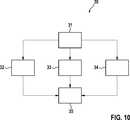
Das Verfahren
Im Verfahrensschritt
Darüber hinaus kann im Verfahrensschritt
Auf den Verfahrensschritt
Die Streckung kann durch Ziehen an der stärker zu streckenden Seite und beispielsweise an der Folie
Optional zum Verfahrensschritt
Alternativ oder zusätzlich zu einem der Verfahrensschritte
Auf jeden der Verfahrensschritte
BezugszeichenlisteLIST OF REFERENCE NUMBERS
- 11
- implantierbare Elektrode implantable electrode
- 22
- Kontaktabschnitt Contact section
- 33
- Kontaktseite Contact
- 44
- Kontaktelement contact element
- 55
- Mantel coat
- 66
- Verbindungsabschnitt connecting portion
- 77
- Außenseite outside
- 88th
- Schmalseite narrow side
- 99
- Innenseite inside
- 1010
- Verbindungsleitung connecting line
- 1111
- Durchkontaktierung via
- 1212
- Halbfabrikat semi-finished product
- 1313
- Folie foil
- 14, 1514, 15
- Nut groove
- 16, 17, 1816, 17, 18
- Abschnitte der Folie Sections of the film
- 1919
- Folie, gestreckt Foil, stretched
- 2020
- Streckwerkzeug stretching tool
- 2121
- Kante edge
- 2222
- Anschlussabschnitt connecting section
- 2323
- Kern core
- 2424
- Körper body
- 2525
- Außenseite des Körpers Outside of the body
- 3030
- Verfahren method
- 3131
- Start begin
- 3232
- Strecken stretch
- 3333
- Wickeln und optional Befestigen Wrap and optionally attach
- 3434
- Beschichten coating
- 3535
- Ende The End
- AA
- Längsachse longitudinal axis
- BB
- Breitenrichtung width direction
- DD
- Längsrichtung des Kontaktabschnitts Longitudinal direction of the contact section
- K1, K2K1, K2
- Kraftpfeil force arrow
- LL
- Längsrichtung des Verbindungsabschnitts Longitudinal direction of the connecting portion
- WW
- Winkel angle
Claims (14)
Translated fromGermanPriority Applications (4)
| Application Number | Priority Date | Filing Date | Title |
|---|---|---|---|
| DE102015121817.8ADE102015121817A1 (en) | 2015-12-15 | 2015-12-15 | Stretchable electrode |
| SG10201609685VASG10201609685VA (en) | 2015-12-15 | 2016-11-18 | Extendable electrode |
| EP16199801.8AEP3181188B1 (en) | 2015-12-15 | 2016-11-21 | Extendable eclectrode |
| US15/359,787US10426948B2 (en) | 2015-12-15 | 2016-11-23 | Extendable electrode |
Applications Claiming Priority (1)
| Application Number | Priority Date | Filing Date | Title |
|---|---|---|---|
| DE102015121817.8ADE102015121817A1 (en) | 2015-12-15 | 2015-12-15 | Stretchable electrode |
Publications (1)
| Publication Number | Publication Date |
|---|---|
| DE102015121817A1true DE102015121817A1 (en) | 2017-06-22 |
Family
ID=57354280
Family Applications (1)
| Application Number | Title | Priority Date | Filing Date |
|---|---|---|---|
| DE102015121817.8AWithdrawnDE102015121817A1 (en) | 2015-12-15 | 2015-12-15 | Stretchable electrode |
Country Status (4)
| Country | Link |
|---|---|
| US (1) | US10426948B2 (en) |
| EP (1) | EP3181188B1 (en) |
| DE (1) | DE102015121817A1 (en) |
| SG (1) | SG10201609685VA (en) |
Families Citing this family (4)
| Publication number | Priority date | Publication date | Assignee | Title |
|---|---|---|---|---|
| EP3840744B1 (en) | 2018-08-21 | 2025-06-04 | Board of Regents, The University of Texas System | Compositions and methods for the treatment of cancer cells by induction of cytotoxic oxidative stress |
| US11878167B2 (en) | 2020-05-04 | 2024-01-23 | Btl Healthcare Technologies A.S. | Device and method for unattended treatment of a patient |
| WO2021224678A1 (en) | 2020-05-04 | 2021-11-11 | Btl Medical Technologies S.R.O. | Device and method for unattended treatment of a patient |
| WO2024033021A1 (en) | 2022-08-10 | 2024-02-15 | Biotronik Se & Co. Kg | Elongate conductor arrangement for electrical connection to a medical device, medical device and method for fabricating an elongate conductor arrangement |
Citations (6)
| Publication number | Priority date | Publication date | Assignee | Title |
|---|---|---|---|---|
| US5522874A (en)* | 1994-07-28 | 1996-06-04 | Gates; James T. | Medical lead having segmented electrode |
| US20030216800A1 (en)* | 2002-04-11 | 2003-11-20 | Medtronic, Inc. | Implantable medical device conductor insulation and process for forming |
| US20090210040A1 (en)* | 2008-02-19 | 2009-08-20 | Ochoa Francisco | Variable length medical electrical stimulation lead |
| US20090281608A1 (en)* | 2008-05-09 | 2009-11-12 | Cardiac Pacemakers, Inc. | Medical lead coil conductor with spacer element |
| US20100331934A1 (en)* | 2009-06-29 | 2010-12-30 | Boston Scientific Neuromodulation Corporation | Multi-element contact assemblies for electrical stimulation systems and systems and methods of making and using |
| US20130158638A1 (en)* | 2011-11-11 | 2013-06-20 | Advanced Neuromodulation Systems, Inc. | Stimulation lead and method of fabrication |
Family Cites Families (10)
| Publication number | Priority date | Publication date | Assignee | Title |
|---|---|---|---|---|
| CA2152604C (en)* | 1993-02-01 | 2000-05-09 | Thomas M. Soukup | An implantable electrode |
| DE102004048991B4 (en)* | 2004-10-04 | 2010-01-28 | Biotronik Crm Patent Ag | electrode line |
| US7630749B2 (en)* | 2005-11-07 | 2009-12-08 | Gore Enterprise Holdings, Inc. | Implantable electrophysiology lead body |
| US20080027524A1 (en)* | 2006-07-26 | 2008-01-31 | Maschino Steven E | Multi-electrode assembly for an implantable medical device |
| DE102006037122B3 (en)* | 2006-08-09 | 2008-04-03 | Osypka, Peter, Dr.-Ing. | Medical electrode with at least two poles and a plug and their use |
| EP2079513B1 (en)* | 2006-10-31 | 2014-07-23 | St. Jude Medical AB | A medical implantable lead including a flexible flat twisted elongate body |
| US20120158109A1 (en)* | 2010-12-20 | 2012-06-21 | Klaus Bartels | Implantable device |
| EP2468354A3 (en)* | 2010-12-21 | 2012-09-05 | BIOTRONIK SE & Co. KG | Implantable device |
| EP2772280A3 (en)* | 2012-02-28 | 2014-09-10 | BIOTRONIK SE & Co. KG | Electrode catheter, in particular for cardiac therapy |
| EP2653187A1 (en)* | 2012-04-20 | 2013-10-23 | Sapiens Steering Brain Stimulation B.V. | A freestanding thin film, especially a freestanding thin film for a system for neural applications |
- 2015
- 2015-12-15DEDE102015121817.8Apatent/DE102015121817A1/ennot_activeWithdrawn
- 2016
- 2016-11-18SGSG10201609685VApatent/SG10201609685VA/enunknown
- 2016-11-21EPEP16199801.8Apatent/EP3181188B1/enactiveActive
- 2016-11-23USUS15/359,787patent/US10426948B2/enactiveActive
Patent Citations (6)
| Publication number | Priority date | Publication date | Assignee | Title |
|---|---|---|---|---|
| US5522874A (en)* | 1994-07-28 | 1996-06-04 | Gates; James T. | Medical lead having segmented electrode |
| US20030216800A1 (en)* | 2002-04-11 | 2003-11-20 | Medtronic, Inc. | Implantable medical device conductor insulation and process for forming |
| US20090210040A1 (en)* | 2008-02-19 | 2009-08-20 | Ochoa Francisco | Variable length medical electrical stimulation lead |
| US20090281608A1 (en)* | 2008-05-09 | 2009-11-12 | Cardiac Pacemakers, Inc. | Medical lead coil conductor with spacer element |
| US20100331934A1 (en)* | 2009-06-29 | 2010-12-30 | Boston Scientific Neuromodulation Corporation | Multi-element contact assemblies for electrical stimulation systems and systems and methods of making and using |
| US20130158638A1 (en)* | 2011-11-11 | 2013-06-20 | Advanced Neuromodulation Systems, Inc. | Stimulation lead and method of fabrication |
Also Published As
| Publication number | Publication date |
|---|---|
| SG10201609685VA (en) | 2017-07-28 |
| EP3181188B1 (en) | 2018-06-20 |
| EP3181188A1 (en) | 2017-06-21 |
| US20170165473A1 (en) | 2017-06-15 |
| US10426948B2 (en) | 2019-10-01 |
Similar Documents
| Publication | Publication Date | Title |
|---|---|---|
| DE69318183T2 (en) | IMPLANTABLE PHYSIOLOGICAL GUIDE | |
| DE69401562T2 (en) | Catheter with an electrode and process for its manufacture | |
| DE69326080T2 (en) | IMPLANTABLE ELECTRODE | |
| DE2719287C2 (en) | Implantable electrode assembly | |
| DE69924082T2 (en) | Active slim tube and method of manufacture | |
| EP3181188B1 (en) | Extendable eclectrode | |
| EP0566850B1 (en) | Controllable electrode device | |
| EP0491979A1 (en) | Pacemaker catheter with two poles | |
| DE1750446A1 (en) | Flexible, rollable shaft with high resistance to tensile and torque loads and their manufacturing process | |
| DE8207842U1 (en) | IMPLANTABLE LINE | |
| DE3140075C2 (en) | ||
| EP1243286B1 (en) | Intravascular electrode lead | |
| DE102016103597A1 (en) | Implantable cuff electrode | |
| DE1125025B (en) | Method of making a stretchable electrical cord | |
| WO2014063994A1 (en) | Microwave cable and method for producing and using such a microwave cable | |
| DE2850315C2 (en) | ||
| DE102009033767B4 (en) | Connection element for conduction coil | |
| CH656313A5 (en) | Electrode with an electrical conductor which is connected to a contact provided for forming a connection with tissue | |
| EP0092797B1 (en) | Multi-pole electrical lead | |
| EP2918308A1 (en) | Insulation tube for an electrical lead for medical use, and method for producing such a tube | |
| EP3181187B1 (en) | Implantable electrode with hollow cylindrical sheath | |
| DE102018204036B4 (en) | Implant in the form of a wound cuff electrode arrangement | |
| DE2907870A1 (en) | Tubular heater with U=shaped resistance heating filament - has ceramic spacer in metal tube which is compressed to close all internal spaces | |
| WO2006007829A1 (en) | Electric connecting cable for implanted components and method for producing said cable | |
| DE102023128041B4 (en) | Electrical connecting line, electrical device and method for producing a connecting line |
Legal Events
| Date | Code | Title | Description |
|---|---|---|---|
| R163 | Identified publications notified | ||
| R119 | Application deemed withdrawn, or ip right lapsed, due to non-payment of renewal fee |