DE102015111097A1 - Control device and fan system - Google Patents
Control device and fan systemDownload PDFInfo
- Publication number
- DE102015111097A1 DE102015111097A1DE102015111097.0ADE102015111097ADE102015111097A1DE 102015111097 A1DE102015111097 A1DE 102015111097A1DE 102015111097 ADE102015111097 ADE 102015111097ADE 102015111097 A1DE102015111097 A1DE 102015111097A1
- Authority
- DE
- Germany
- Prior art keywords
- fan
- operating voltage
- fan motor
- motors
- speed
- Prior art date
- Legal status (The legal status is an assumption and is not a legal conclusion. Google has not performed a legal analysis and makes no representation as to the accuracy of the status listed.)
- Withdrawn
Links
- 238000001514detection methodMethods0.000claimsdescription5
- 238000012545processingMethods0.000claimsdescription2
- 238000010586diagramMethods0.000description8
- 238000011161developmentMethods0.000description3
- 230000018109developmental processEffects0.000description3
- 238000005259measurementMethods0.000description3
- 230000002411adverseEffects0.000description2
- 230000003213activating effectEffects0.000description1
- 230000006978adaptationEffects0.000description1
- 238000013459approachMethods0.000description1
- 230000002457bidirectional effectEffects0.000description1
- 238000001816coolingMethods0.000description1
- 230000001186cumulative effectEffects0.000description1
- 230000009849deactivationEffects0.000description1
- 238000013461designMethods0.000description1
- 230000009977dual effectEffects0.000description1
- 230000000694effectsEffects0.000description1
- 239000011159matrix materialSubstances0.000description1
- 238000000034methodMethods0.000description1
- 238000012544monitoring processMethods0.000description1
- 230000002093peripheral effectEffects0.000description1
- 238000000926separation methodMethods0.000description1
- 230000011664signalingEffects0.000description1
- 238000011144upstream manufacturingMethods0.000description1
Images


Classifications
- H—ELECTRICITY
- H05—ELECTRIC TECHNIQUES NOT OTHERWISE PROVIDED FOR
- H05K—PRINTED CIRCUITS; CASINGS OR CONSTRUCTIONAL DETAILS OF ELECTRIC APPARATUS; MANUFACTURE OF ASSEMBLAGES OF ELECTRICAL COMPONENTS
- H05K7/00—Constructional details common to different types of electric apparatus
- H05K7/20—Modifications to facilitate cooling, ventilating, or heating
- H05K7/20009—Modifications to facilitate cooling, ventilating, or heating using a gaseous coolant in electronic enclosures
- H05K7/20209—Thermal management, e.g. fan control
- F—MECHANICAL ENGINEERING; LIGHTING; HEATING; WEAPONS; BLASTING
- F04—POSITIVE - DISPLACEMENT MACHINES FOR LIQUIDS; PUMPS FOR LIQUIDS OR ELASTIC FLUIDS
- F04D—NON-POSITIVE-DISPLACEMENT PUMPS
- F04D27/00—Control, e.g. regulation, of pumps, pumping installations or pumping systems specially adapted for elastic fluids
- F04D27/004—Control, e.g. regulation, of pumps, pumping installations or pumping systems specially adapted for elastic fluids by varying driving speed
- H—ELECTRICITY
- H05—ELECTRIC TECHNIQUES NOT OTHERWISE PROVIDED FOR
- H05K—PRINTED CIRCUITS; CASINGS OR CONSTRUCTIONAL DETAILS OF ELECTRIC APPARATUS; MANUFACTURE OF ASSEMBLAGES OF ELECTRICAL COMPONENTS
- H05K7/00—Constructional details common to different types of electric apparatus
- H05K7/20—Modifications to facilitate cooling, ventilating, or heating
- H05K7/20009—Modifications to facilitate cooling, ventilating, or heating using a gaseous coolant in electronic enclosures
- H05K7/20136—Forced ventilation, e.g. by fans
- H05K7/2019—Fan safe systems, e.g. mechanical devices for non stop cooling
- F—MECHANICAL ENGINEERING; LIGHTING; HEATING; WEAPONS; BLASTING
- F05—INDEXING SCHEMES RELATING TO ENGINES OR PUMPS IN VARIOUS SUBCLASSES OF CLASSES F01-F04
- F05D—INDEXING SCHEME FOR ASPECTS RELATING TO NON-POSITIVE-DISPLACEMENT MACHINES OR ENGINES, GAS-TURBINES OR JET-PROPULSION PLANTS
- F05D2270/00—Control
- F05D2270/40—Type of control system
- F05D2270/46—Type of control system redundant, i.e. failsafe operation
- Y—GENERAL TAGGING OF NEW TECHNOLOGICAL DEVELOPMENTS; GENERAL TAGGING OF CROSS-SECTIONAL TECHNOLOGIES SPANNING OVER SEVERAL SECTIONS OF THE IPC; TECHNICAL SUBJECTS COVERED BY FORMER USPC CROSS-REFERENCE ART COLLECTIONS [XRACs] AND DIGESTS
- Y02—TECHNOLOGIES OR APPLICATIONS FOR MITIGATION OR ADAPTATION AGAINST CLIMATE CHANGE
- Y02B—CLIMATE CHANGE MITIGATION TECHNOLOGIES RELATED TO BUILDINGS, e.g. HOUSING, HOUSE APPLIANCES OR RELATED END-USER APPLICATIONS
- Y02B30/00—Energy efficient heating, ventilation or air conditioning [HVAC]
- Y02B30/70—Efficient control or regulation technologies, e.g. for control of refrigerant flow, motor or heating
Landscapes
- Engineering & Computer Science (AREA)
- Microelectronics & Electronic Packaging (AREA)
- Physics & Mathematics (AREA)
- Thermal Sciences (AREA)
- Mechanical Engineering (AREA)
- General Engineering & Computer Science (AREA)
- Control Of Multiple Motors (AREA)
Abstract
Translated fromGermanDescription
Translated fromGermanDie vorliegende Erfindung betrifft eine Ansteuervorrichtung für eine Mehrzahl von elektrisch betriebenen Lüftermotoren nach dem Oberbegriff des Hauptanspruchs. Ferner betrifft die vorliegende Erfindung ein Lüftersystem, welches in modulartiger Realisierung eine solche Ansteuervorrichtung mit mehreren Lüftermotoren kombiniert.The present invention relates to a drive device for a plurality of electrically operated fan motors according to the preamble of the main claim. Furthermore, the present invention relates to a fan system, which combines in modular implementation such a drive device with multiple fan motors.
Aus dem Stand der Technik sind Lüftersysteme, bei welchen – bevorzugt modulartig und damit gemeinsam handhabbar – eine Mehrzahl von Lüftermotoren in einer Trägervorrichtung angeordnet und an einen zu belüftenden Einsatzort bringbar sind, allgemein bekannt. Typische Anwendungsfälle sind etwa Anlagen der Informations- oder Funktechnologie, wobei dieses Anwendungsgebiet gleichwohl nicht beschränkend für diese Anwendung ist. Um in der notwendigen Weise zu kühlende Aggregate mit einem Luftstrom zu versehen, werden die modulartig in einem geeigneten Modulgehäuse angeordneten elektrischen Lüftermotoren mit geeigneten, typischerweise am Einsatzort vorhandenen Betriebsspannungsquellen beschaltet, wobei eine typische Betriebsspannung einer derartigen Betriebsspannungsquelle unterhalb 30 V und eine maximale Leistungsaufnahme der in Mehrzahl im Lüftersystem vorgesehenen bzw. vorzusehenden Lüftermotoren im Bereich zwischen ca. 5 W und 10 W liegt.In the prior art are fan systems in which - preferably modular and thus handled together - a plurality of fan motors are arranged in a carrier device and can be brought to a place to be ventilated, generally known. Typical applications are, for example, systems of information or radio technology, although this field of application is non-limiting for this application. In order to provide in the necessary manner to be cooled units with an air flow, the modularly arranged in a suitable module housing electric fan motors with suitable, typically present on site operating voltage sources are connected, with a typical operating voltage of such operating voltage source below 30 V and a maximum power consumption of in Most provided in the fan system or to be provided fan motors in the range between about 5 W and 10 W is.
Eine konventionelle Vorgehensweise bei der Betriebsspannungsversorgung von in Mehrzahl vorgesehener Lüftermotoren, etwa bei den bekannten Modulen, besteht darin, sowohl die Lüftermotoren als Verbraucher zueinander parallel zu schalten, als auch, im Fall mehrerer Betriebspannungsquellen, diese eingangsseitig parallel zu schalten. Entsprechend würde eine als bekannt vorauszusetzende Ansteuervorrichtung für eine Mehrzahl von Lüftermotoren eingangs- und ausgangsseitig jeweils einfache Parallelschaltungen aufweisen. Wenn dann etwa eingangsseitig eine der Spannungsquellen ausfällt oder aus anderen Gründen nicht mehr für eine Betriebsspannungsversorgung zur Verfügung steht, würde dann eine jeweils verbleibende für die angeschlossene Mehrzahl der Lüftermotoren entsprechend höher belastet. Dies kann, etwa bei großzügiger Dimensionierung, unproblematisch sein, es besteht jedoch auch die Gefahr einer Überlastung bzw. elektrischen Überbelastung der verbleibenden Betriebsspannungsquelle, insbesondere wenn die angeschlossenen Lüftermotoren als Verbraucher jeweils maximale elektrische Leistung abfordern.A conventional approach to the operating voltage supply of a plurality of provided fan motors, such as in the known modules, is to switch both the fan motors as a load parallel to each other, as well as, in the case of multiple operating voltage sources, these input side to switch parallel. Correspondingly, a control device for a plurality of fan motors which is to be presupposed as known would have simple parallel connections on the input and output sides. If, for example, one of the voltage sources fails on the input side or is no longer available for an operating voltage supply for other reasons, then a respectively remaining one for the connected plurality of fan motors would be loaded correspondingly higher. This can be unproblematic, for example with generous dimensioning, but there is also the risk of overloading or electrical overloading of the remaining operating voltage source, in particular if the connected fan motors as consumers each demand maximum electrical power.
Umgekehrt würde ein Ausfall eines der Lüftermotoren dann unkritisch sein, wenn dieser Ausfall keinen (bezogen auf die Ansteuervorrichtung) ausgangsseitigen Kurzschluss erzeugt, auch hier sind nachteilige Effekte jedoch auf verbleibende, in reduzierter Anzahl angetriebene der Lüftermotoren nicht ausgeschlossen, etwa durch einen mit dem ausgefallenen Lüftermotor verbundenen negativen Einfluss auf eine dann anliegende Lüfter-Betriebsspannung.Conversely, a failure of one of the fan motors would be uncritical if this failure does not produce (based on the drive device) output short circuit, but here are adverse effects on remaining, driven in reduced number of the fan motors not excluded, such as one with the failed fan motor connected negative influence on a then applied fan operating voltage.
Ein weiterer Nachteil einer existierenden Anschluss- bzw. Stromversorgungstechnologie für eine Mehrzahl von Lüftermotoren (typischerweise mit einer Mehrzahl von Betriebsspannungsquellen) liegt darin, dass die Zuordnung, etwa im Hinblick auf bereitgestellte elektrische Leistung durch die Betriebsspannungsquellen sowie kumulative elektrische Leistungsaufnahme durch die Lüftermotoren, eine jeweils angepasste Konfiguration erfordert, welche wenig flexibel ist und insbesondere nicht kurzfristig an sich ändernden Voraussetzungen anpassbar ist. Hinzu kommt der potenzielle Nachteil, dass derartige konfigurierte Anordnungen üblicherweise nicht im laufenden Betrieb der Lüfter ersetzbar sind – sog. hot swap – mit der nachteiligen Konsequenz, dass zum Austauschen eines Lüftermoduls im Regelfall zumindest die Betriebsspannungsanordnung deaktiviert werden muss, ggf. sogar die vollständige, durch das betreffende Lüftermodul zu belüftende Infrastruktur. Gerade im sensiblen Bereich der Informations- oder Telekommunikationstechnologie führt dies dann zu nachteiligen Betriebsunterbrechungen, welche gleichermaßen zu vermeiden sind.Another disadvantage of an existing power supply technology for a plurality of fan motors (typically with a plurality of operating voltage sources) is that the allocation, for instance with regard to provided electrical power by the operating voltage sources and cumulative electrical power consumption by the fan motors, one each customized configuration is required, which is not very flexible and in particular can not be adapted in the short term to changing conditions. In addition, there is the potential disadvantage that such configured arrangements are usually not replaceable during operation of the fan - so-called hot swap - with the disadvantageous consequence that for replacing a fan module usually at least the operating voltage arrangement must be disabled, possibly even the complete, through the relevant fan module to be ventilated infrastructure. Especially in the sensitive field of information or telecommunications technology, this then leads to adverse business interruptions, which are equally to avoid.
Aufgabe der vorliegenden Erfindung ist es daher, eine Ansteuervorrichtung für eine Mehrzahl von elektrisch betriebenen Lüftermotoren zu schaffen, welche flexibel im Einsatz und in der Anpassbarkeit an eine Mehrzahl von Betriebsspannungsquellen ist, dabei insbesondere unempfindlich gegenüber einem Ausfall eines oder mehrerer der angeschlossenen Betriebsspannungsquellen ist und gleichwohl einen zuverlässigen Betrieb der ausgangsseitig angeschlossenen Lüftermotoren gewährleistet. Zusätzlich soll eine derartige Ansteuervorrichtung, insbesondere in Kombination mit der Mehrzahl anzusteuernder Lüftermotoren, einfach und kompakt integrierbar sein und dabei für elektronische Erfassungszwecke zuverlässige Betriebsstatusinformationen bereitstellen können.Object of the present invention is therefore to provide a drive device for a plurality of electrically operated fan motors, which is flexible in use and adaptability to a plurality of operating voltage sources, in particular insensitive to a failure of one or more of the connected operating voltage sources and nevertheless Ensures reliable operation of the fan motors connected on the output side. In addition, such a drive device, in particular in combination with the plurality of fan motors to be controlled, be easy and compact to be integrated and can provide reliable operating status information for electronic detection purposes.
Die Aufgabe wird durch die Ansteuervorrichtung für eine Mehrzahl von elektrisch betriebenen Lüftermotoren nach dem Hauptanspruch gelöst; vorteilhafte Weiterbildungen der Erfindung sind in den Unteransprüchen beschrieben. Zusätzlich wird Schutz beansprucht im Rahmen der Erfindung für ein Lüftersystem unter Nutzung einer derartigen Ansteuervorrichtung, welches zusätzlich mindestens einen der ersten Lüftermotoren und mindestens einen der zweiten Lüftermotoren aufweist und bevorzugt modular bzw. in ein Modulgehäuse integriert ausgestaltet ist.The object is achieved by the drive device for a plurality of electrically driven fan motors according to the main claim; advantageous developments of the invention are described in the subclaims. In addition, protection is claimed in the context of the invention for a fan system using such a drive device, which additionally has at least one of the first fan motors and at least one of the second fan motors and is preferably designed to be modular or integrated into a module housing.
In erfindungsgemäß vorteilhafter Weise weist die Ansteuervorrichtung elektronische Steuermittel auf, die zum Detektieren einer sowohl am ersten, als auch am zweiten Betriebsspannungseingangsanschluss für eine jeweilige Betriebsspannungsquelle anliegenden Spannungen ausgebildet sind. Die Steuermittel sind ferner zum Ausgeben einer Mehrzahl von eine Lüftermotordrehzahl und/oder eine elektrische Lüftermotorleistungsaufnahme steuernden Steuersignalen an Lüfterversorgungsanschlüsse für die jeweiligen Lüftermotoren ausgebildet, wobei die Erfindung hier zwei Betriebsspannungsversorgungsmodi vorsieht. Bei einem ersten erfindungsgemäßem Betriebsspannungsversorgungsmodus, insoweit ein Modus für ausreichende Betriebsspannung sowohl am ersten als auch am zweiten Betriebsspannungseingangsanschluss, würde eine höhere Lüftermotordrehzahl bzw. eine höhere Lüftermotorleistung für die angeschlossenen ersten bzw. zweiten Lüftermotoren angesteuert, wobei dies durch Vergleichen der erfassten (Betriebs-)Spannungen auf dem ersten und zweiten Betriebsspannungseingangsanschluss relativ zu einem geeigneten vorbestimmten Spannungsschwellwert erfolgt. Für den Fall jedoch, dass (mindestens) eine Betriebsspannung auf einen zugehörigen Betriebsspannungseingangsanschluss unter diesen Schwellwert fällt, erkennen die erfindungsgemäßen elektronischen Steuermittel im zweiten Betriebsspannungsversorgungsmodus auf eine mögliche Fehler- bzw. Störsituation, woraufhin dann eine niedrigere Lüftermotordrehzahl bzw. eine niedrigere Lüftermotorleistung für die angeschlossene bzw. anzuschließenden Lüftermotoren am ersten und zweiten Lüfterversorgungsanschluss angesteuert wird. Dabei sind die Begriffe „höher” und „niedriger” bezogen auf die Drehzahl bzw. die elektrische Leistung relativ zu verstehen und stellen auf das Verhältnis der beiden Modi ab; dem Fachmann obliegt es, hier jeweils konkrete Werte (auch etwa bezogen auf eine Nenndrehzahl bzw. -leistung als „höher” oder „niedriger”) einzurichten. In an advantageous manner according to the invention, the drive device has electronic control means which are designed to detect a voltage present at both the first and the second operating voltage input connection for a respective operating voltage source. The control means are further adapted for outputting a plurality of fan motor speed and / or electric fan motor power receiving control signals to fan supply terminals for the respective fan motors, the invention providing two operating voltage supply modes herein. In a first inventive operating voltage supply mode, insofar as a mode for sufficient operating voltage at both the first and the second operating voltage input terminal, a higher fan motor speed or a higher fan motor power for the connected first and second fan motors would be controlled, by comparing the detected (operating) Voltages occur on the first and second operating voltage input terminals relative to a suitable predetermined voltage threshold. However, in the event that (at least) one operating voltage drops to an associated operating voltage input terminal below this threshold, the electronic control means of the present invention will detect a potential fault condition in the second power supply mode, whereupon a lower fan motor speed or fan motor power for the connected one or to be connected fan motors is driven at the first and second fan supply connection. The terms "higher" and "lower" relative to the speed or the electrical power relative to understand and are based on the ratio of the two modes; It is up to the person skilled in the art to set up concrete values (also referred to a nominal speed or power as "higher" or "lower").
Die Erfindung sieht hierfür weiterbildend vor, dass im Fall des Ausfalls einer Betriebsspannungsquelle dann eine bzw. die jeweils andere Betriebsspannungsquelle durch entsprechende weiterbildende Verschaltung, insbesondere in Form des weiterbildenden Verbindungssteuersignals der elektronischen Steuermittel, das gemeinsame Bereitstellen des (verbleibenden) Eingangssignals für alle Verbraucher bewirkt.The invention provides for this further, that in case of failure of an operating voltage source then one or the other operating voltage source by appropriate further education interconnection, in particular in the form of further developing connection control signal of the electronic control means, the common provision of the (remaining) input signal for all consumers causes.
Damit ermöglicht die Erfindung in dieser prinzipiellen Funktionalität bereits die flexible Anpassung an eine konkret vorhandene Betriebsspannungsversorgungssituation, nämlich dergestalt, dass eine Betrieb mit hoher Drehzahl bzw. Volllast nur dann ermöglicht wird, wenn tatsächlich eingangsseitig und durch Vorhandensein ausreichender Spannung an beiden Lüfterversorgungsanschlüssen die eingangsseitigen elektrischen Leistungsvoraussetzungen vorhanden sind. Dagegen würde, insbesondere zum Zweck des Verhinderns einer Überlast bzw. elektrischen Überbelastung einer verbleibenden Betriebsspannungsquelle, im zweiten Betriebsspannungsversorgungsmodus eine Lüfterdrehzahl und damit eine elektrische Leistungsaufnahme der mehreren angeschlossenen Lüfter abgesenkt, so dass auch in diesem Zustand ein ordnungsgemäßer Betrieb ohne Überlast sichergestellt ist.Thus, the invention in this basic functionality already allows the flexible adaptation to a specific operating power supply situation, namely such that operation at high speed or full load is only possible if the input side electrical performance requirements actually on the input side and by the presence of sufficient voltage at both fan supply connections available. In contrast, in particular for the purpose of preventing an overload or electrical overloading of a remaining operating voltage source, a fan speed and thus an electrical power consumption of the plurality of connected fans lowered in the second operating voltage supply mode, so that even in this state proper operation is ensured without overload.
Weiterbildend weisen dafür die Lüfterversorgungsanschlüsse jeweils einen Lüftersignalanschluss auf, welcher zum Verbinden mit einem bevorzugt digitalen Steuersignalanschluss des jeweils zu verbindenden Lüftermotors versehen ist. Insoweit als bevorzugte Realisierungsform der Erfindung ist nämlich zum Zusammenwirken mit der Ansteuervorrichtung eine Anordnung aus Lüftermotoren vorgesehen, welche jeweils, neben einem elektrischen Betriebsspannungsanschluss, einen digitalen Steuerkanal als Steueranschluss aufweisen, wobei weiter bevorzugt in Form von gepulsten, weiter bevorzugt pulsweitenmodulierten Steuersignalen dann die Drehzahl- bzw. Leistungseinstellung des angeschlossenen Lüftermotors erfolgt.For further development, the fan supply connections each have a fan signal connection, which is provided for connection to a preferably digital control signal connection of the respective fan motor to be connected. In that regard, as a preferred embodiment of the invention, an arrangement of fan motors is provided for cooperation with the drive device, which in each case, in addition to an electrical operating voltage terminal, a digital control channel as a control terminal, more preferably in the form of pulsed, more preferably pulse width modulated control signals then the speed or power setting of the connected fan motor takes place.
Wiederum weiterbildend, entweder als zusätzlicher Anschluss bzw. zusätzliche Leitung, alternativ im Rahmen einer gemeinsam und bidirektional genutzten Leitung, kann der Lüftersignalanschluss ein von einem Lüftermotor erzeugtes, weiter bevorzugt digitales Ausgangssignal, etwa ein Drehzahlsignal, erfassen und wiederum den elektronischen Steuermitteln zur Verarbeitung anlegen, so dass diesbezüglich einerseits eine Rückmeldung im Hinblick auf tatsächlich realisierte Lüfterdrehzahlen möglich ist, darüber hinaus etwa auch dann durch die elektronischen Steuermittel, und über wiederum weiterbildend und vorteilhaft zusätzliche Status- und/oder Alarmsignalanschlüsse, weiter bevorzugt den jeweiligen Betriebsspannungseingangsanschlüssen zugeordnet, eine Signalisierung des entsprechenden Betriebs-, Alarm- oder Fehlerstatus nach extern erfolgen kann.Once again, either as an additional connection or additional line, alternatively as part of a shared and bidirectionally used line, the fan signal terminal can detect a preferably digital output signal generated by a fan motor, such as a speed signal, and in turn apply the electronic control means for processing. so that in this regard on the one hand a feedback in terms of actually realized fan speeds is possible, moreover about even by the electronic control means, and in turn weiterbildend and advantageous additional status and / or alarm signal terminals, more preferably associated with the respective operating voltage input terminals, signaling the corresponding Operational, alarm or error status can be made externally.
In einer weiteren bevorzugten Weiterbildung der Erfindung, insbesondere unter Nutzung des vorteilhaften Lüfterdrehzahlsignals, ist die Erfindung durch Ausgestaltung der elektronischen Steuermittel so weitergebildet, dass als Reaktion auf ein unterhalb eines vorbestimmten Drehzahlschwellwerts liegendes erfasstes Lüfterdrehzahlsignal (etwa für einen der angeschlossenen bzw. anzuschließenden Lüftermotoren) eine Drehzahlerhöhung bzw. eine Leistungserhöhung mindestens eines weiteren der angeschlossenen Lüftermotoren erfolgen kann. Auf diese Weise ist es möglich, flexibel auf Lüfterbedingungen eines Lüfters – etwa drehzahlsenkende Verschmutzung oder dgl. – zu reagieren und durch das Anheben von Drehzahlen anderer Lüfter dann gleichwohl in der Gesamtanordnung eine weitgehend gleichbleibende Lüfterleistung sicherzustellen.In a further preferred embodiment of the invention, in particular using the advantageous fan speed signal, the invention is further developed by designing the electronic control means that in response to a below a predetermined speed threshold detected detected fan speed signal (such as one of the connected or to be connected fan motors) Increasing the speed or increasing the power of at least one other of the connected fan motors can take place. In this way, it is possible to flexibly fan conditions of a fan - such as speed-reducing pollution or the like. - To respond and by lifting of speeds of other fans then nevertheless in the overall arrangement to ensure a largely constant fan performance.
Zusätzlich vorteilhaft weiterbildend sieht die Erfindung vor, dass den elektronischen Steuermitteln Temperaturerfassungsmittel zugeordnet sind. Diese sind weiterbildend ausgebildet, eine Betriebstemperatur entweder der Steuermittel selbst, ergänzend oder alternativ eines oder mehrerer der – modulartig – angeordneten Lüfter, vorzunehmen und als Reaktion auf dieses Temperatursignal wiederum Anpassungen einer jeweiligen Lüfterleistung bzw. Lüfterdrehzahl vorzunehmen. Dies hat einerseits den Zweck, thermische Überbelastungen zu verhindern, andererseits kann etwa auch, durch gezielte, temperaturbedingte Erhöhung, auf Änderungen in einer Umgebungstemperatur reagiert werden.In addition to providing an advantageous further development, the invention provides that temperature-determining means are assigned to the electronic control means. These are designed to further develop an operating temperature of either the control means itself, in addition or alternatively one or more of the - modular - arranged fan to make and in turn make adjustments to a respective fan power or fan speed in response to this temperature signal. On the one hand, this has the purpose of preventing thermal overloading, on the other hand, it is also possible, for example, to react to changes in an ambient temperature by targeted, temperature-induced increase.
Während es im Rahmen der vorliegenden Erfindung bevorzugt ist (und auch als Verwendung als zur Erfindung gehörig beansprucht wird), die erfindungsgemäße Ansteuervorrichtung und/oder das erfindungsgemäße Lüftersystem unter Nutzung der Ansteuervorrichtung für Lüfter-Anwendungszwecke der Informationstechnologie oder der Funktechnologie zu verwenden, ist die vorliegende Erfindung gleichwohl nicht auf diesen Einsatzfall beschränkt. Vielmehr gestattet es die vorliegende Erfindung, flexibel auf wechselnde Betriebsspannungsversorgungsbedingungen sowie Lüftersituationen für nahezu beliebige Einsatzkontexte zu reagieren.While it is preferred within the scope of the present invention (and also claimed as being used as the invention) to use the drive device and / or the fan system according to the present invention for information technology or radio technology using the fan application drive device of the present invention Invention, however, not limited to this application. Rather, the present invention allows flexible response to changing operating voltage supply conditions as well as fan situations for almost any application contexts.
Weiter Vorteile, Merkmale und Einzelheiten der Erfindung ergeben sich aus der nachfolgenden Beschreibung bevorzugter Ausführungsbeispiele sowie anhand der Zeichnungen; diese zeigen in:Further advantages, features and details of the invention will become apparent from the following description of preferred embodiments and from the drawings; these show in:
Die
Im gezeigten Ausführungsbeispiel sind die Lüftermotoren
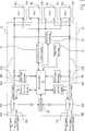
Das Blockdiagramm der
Den Hardware-Kern der erfindungsgemäßen Ansteuervorrichtung gemäß Blockschaltbild der
Abhängig von dem Umstand, ob auf den Leitungen
Für den Fall jedoch, dass, durch entsprechenden Vergleich mit einer Schwellspannung – die
Um jedoch in diesem Zustand zu verhindern, dass die Last der vier Lüftermotoren die eine (verbleibende) Betriebsspannungsquelle zu hoch belastet, wird über eine der Mikrocontrollereinheit
Gleichzeitig empfängt die Steuerschaltung
Um zusätzlich extern signalisieren zu können, dass im zweiten Betriebsspannungsversorgungsmodus lediglich eine der angeschlossenen Betriebsspannungsversorgungsquellen auf alle Lüftermotoren verteilt wird, sind der Mikrocontrollereinheit
Das Ablaufdiagramm der
Falls dies in beiden Fällen zu bejahen ist, bezeichnet als dual radio mode, erfolgt in der Einheit
Dagegen führt sowohl ein Verneinen im Schritt S2, als auch ein Verneinen im Schritt S3 jeweils zum zweiten Betriebsversorgungsmodus, nämlich dem Umstand, dass auf einer der beiden Spannungsversorgungsleitungen
Die vorliegende Erfindung ist nicht auf die gezeigte konkrete Konfiguration von zwei Betriebsspannungsquellen mit vier Lüftermotoren beschränkt, noch auf die gezeigte oder ähnliche Ausgestaltung als Modul.The present invention is not limited to the specific configuration shown of two operating voltage sources with four fan motors, nor to the illustrated or similar embodiment as a module.
Vielmehr liegt es im Rahmen der vorliegenden Erfindung, beliebige Konfigurationen einer Mehrzahl von Lüftermotoren mit einer Mehrzahl von Eingangsspannungsquellen in geeigneter Weise auszugestalten, wobei die exemplarische Verwendung zur Kühlung einer IT- oder Funkeinheit zwar bevorzugt, aber gleichermaßen nicht beschränkend ist.Rather, it is within the scope of the present invention to suitably design any configurations of a plurality of fan motors having a plurality of input voltage sources, although the exemplary use for cooling an IT or radio unit is preferred, but not equally restrictive.
Claims (11)
Translated fromGermanPriority Applications (1)
| Application Number | Priority Date | Filing Date | Title |
|---|---|---|---|
| DE102015111097.0ADE102015111097A1 (en) | 2015-07-09 | 2015-07-09 | Control device and fan system |
Applications Claiming Priority (1)
| Application Number | Priority Date | Filing Date | Title |
|---|---|---|---|
| DE102015111097.0ADE102015111097A1 (en) | 2015-07-09 | 2015-07-09 | Control device and fan system |
Publications (1)
| Publication Number | Publication Date |
|---|---|
| DE102015111097A1true DE102015111097A1 (en) | 2017-01-12 |
Family
ID=57583524
Family Applications (1)
| Application Number | Title | Priority Date | Filing Date |
|---|---|---|---|
| DE102015111097.0AWithdrawnDE102015111097A1 (en) | 2015-07-09 | 2015-07-09 | Control device and fan system |
Country Status (1)
| Country | Link |
|---|---|
| DE (1) | DE102015111097A1 (en) |
Cited By (1)
| Publication number | Priority date | Publication date | Assignee | Title |
|---|---|---|---|---|
| CN110566490A (en)* | 2019-08-30 | 2019-12-13 | 深圳微步信息股份有限公司 | Fan double-control circuit and multi-path fan control device |
Citations (7)
| Publication number | Priority date | Publication date | Assignee | Title |
|---|---|---|---|---|
| DE10044742A1 (en)* | 1999-09-15 | 2001-04-19 | Bosch Gmbh Robert | Electronically commutated motor |
| DE10052726A1 (en)* | 2000-02-22 | 2001-09-06 | Delta Electronics Inc | Multi-motor arrangement and method for controlling it |
| DE102006032512A1 (en)* | 2005-10-07 | 2007-04-26 | Delta Electronics, Inc., Kuei San | System for dissipating heat |
| DE102008041236A1 (en)* | 2008-08-13 | 2010-02-18 | Brose Fahrzeugteile GmbH & Co. Kommanditgesellschaft, Würzburg | Drive device operating method for multiple-fan arrangement of passenger motor vehicle, involves operating electric motors in operating mode, where operating mode is scheduled starting from total output of multiple-fan arrangement |
| DE102009042905A1 (en)* | 2008-09-24 | 2010-05-06 | Fanuc Ltd. | Servomotor controller for controlling servomotors for calculating the absorbed and recovered electrical energy |
| DE102011085335A1 (en)* | 2010-11-04 | 2012-05-10 | Dell Products L.P. | ON RACK LEVEL MODULAR SERVER AND STORE FRAMEWORK |
| US9037309B2 (en)* | 2012-09-26 | 2015-05-19 | Inventec (Pudong) Technology Corporation | Rack server system and operating method thereof |
- 2015
- 2015-07-09DEDE102015111097.0Apatent/DE102015111097A1/ennot_activeWithdrawn
Patent Citations (7)
| Publication number | Priority date | Publication date | Assignee | Title |
|---|---|---|---|---|
| DE10044742A1 (en)* | 1999-09-15 | 2001-04-19 | Bosch Gmbh Robert | Electronically commutated motor |
| DE10052726A1 (en)* | 2000-02-22 | 2001-09-06 | Delta Electronics Inc | Multi-motor arrangement and method for controlling it |
| DE102006032512A1 (en)* | 2005-10-07 | 2007-04-26 | Delta Electronics, Inc., Kuei San | System for dissipating heat |
| DE102008041236A1 (en)* | 2008-08-13 | 2010-02-18 | Brose Fahrzeugteile GmbH & Co. Kommanditgesellschaft, Würzburg | Drive device operating method for multiple-fan arrangement of passenger motor vehicle, involves operating electric motors in operating mode, where operating mode is scheduled starting from total output of multiple-fan arrangement |
| DE102009042905A1 (en)* | 2008-09-24 | 2010-05-06 | Fanuc Ltd. | Servomotor controller for controlling servomotors for calculating the absorbed and recovered electrical energy |
| DE102011085335A1 (en)* | 2010-11-04 | 2012-05-10 | Dell Products L.P. | ON RACK LEVEL MODULAR SERVER AND STORE FRAMEWORK |
| US9037309B2 (en)* | 2012-09-26 | 2015-05-19 | Inventec (Pudong) Technology Corporation | Rack server system and operating method thereof |
Cited By (2)
| Publication number | Priority date | Publication date | Assignee | Title |
|---|---|---|---|---|
| CN110566490A (en)* | 2019-08-30 | 2019-12-13 | 深圳微步信息股份有限公司 | Fan double-control circuit and multi-path fan control device |
| CN110566490B (en)* | 2019-08-30 | 2025-06-17 | 深圳微步信息股份有限公司 | A fan dual control circuit and multi-channel fan control device |
Similar Documents
| Publication | Publication Date | Title |
|---|---|---|
| DE112012006338T5 (en) | LED backlight system and display device | |
| DE212015000103U1 (en) | Energy efficient power sequencer control circuit | |
| DE102006030448B4 (en) | Safe output circuit with a single-channel peripheral connection for the output of a bus participant | |
| DE102013219141A1 (en) | Interlock circuit for securing an electrical vehicle electrical system | |
| DE10315178B4 (en) | Open circuit error detection circuit | |
| EP3078112A1 (en) | Actuator having a position sensor | |
| DE19826028B4 (en) | Device for monitoring a cable used in a vehicle | |
| DE102017127983A1 (en) | FUSE MODULE AND FIELD BUS SYSTEM WITH FUSE MODULE | |
| EP1364459A2 (en) | Safety switch device | |
| DE212012000249U1 (en) | Device for intrinsically safe supply, control and / or evaluation of field devices in the explosion-proof area | |
| DE102015111097A1 (en) | Control device and fan system | |
| DE102004009623B3 (en) | Method of controlling a fan connected to a socket such for use in a computer to cool heat generating components having two operating modes depending on the rotation rate | |
| DE102010037995B4 (en) | Power supply unit and power supply system with the same | |
| DE102010038459A1 (en) | Safety system, has safety module comprising system interface for direct contacting and communication with group protection unit, and load branch comprising another system interface for direct communication with safety module | |
| EP1932400B1 (en) | Apparatus for detecting fault currents in an electronic device | |
| DE102007036680B4 (en) | Circuit device for detecting a broken ground line | |
| DE10332578B4 (en) | Protection circuit and a method for operating the protection circuit, in particular for overvoltage protection of an electronic control system for a motor vehicle | |
| EP1396062A2 (en) | Polarity reversal protection circuit for energy sources | |
| DE102011084147B4 (en) | Device for location-dependent configuration | |
| EP2149956B1 (en) | Modular electrical system and method for its operation | |
| DE10211099A1 (en) | Device for driving electric load has control/evaluation unit with bi-directional configurable port operable as output for control signal to line connected to port or as input for sensing line signal | |
| DE202015106847U1 (en) | Fan with status signal generation and transmission of the status signal via a supply line | |
| DE102023135344A1 (en) | Electrical device and method for operating an electrical device | |
| EP3346352B1 (en) | Electronic functional group | |
| EP3449556B1 (en) | Driving system for electrical motor fed with an inverter |
Legal Events
| Date | Code | Title | Description |
|---|---|---|---|
| R012 | Request for examination validly filed | ||
| R016 | Response to examination communication | ||
| R082 | Change of representative | Representative=s name:PATENTANWAELTE STAEGER & SPERLING PARTNERSCHAF, DE | |
| R119 | Application deemed withdrawn, or ip right lapsed, due to non-payment of renewal fee |