DE102015105668A1 - Composite hose for repairing leaky fluid lines, method of making such a composite hose, and method of repairing leaky fluid lines with a composite hose - Google Patents
Composite hose for repairing leaky fluid lines, method of making such a composite hose, and method of repairing leaky fluid lines with a composite hoseDownload PDFInfo
- Publication number
- DE102015105668A1 DE102015105668A1DE102015105668.2ADE102015105668ADE102015105668A1DE 102015105668 A1DE102015105668 A1DE 102015105668A1DE 102015105668 ADE102015105668 ADE 102015105668ADE 102015105668 A1DE102015105668 A1DE 102015105668A1
- Authority
- DE
- Germany
- Prior art keywords
- film
- composite hose
- composite
- fluid line
- textile
- Prior art date
- Legal status (The legal status is an assumption and is not a legal conclusion. Google has not performed a legal analysis and makes no representation as to the accuracy of the status listed.)
- Granted
Links
- 239000002131composite materialSubstances0.000titleclaimsabstractdescription100
- 239000012530fluidSubstances0.000titleclaimsabstractdescription97
- 238000000034methodMethods0.000titleclaimsabstractdescription57
- 238000004519manufacturing processMethods0.000titleclaimsabstractdescription14
- 239000004753textileSubstances0.000claimsabstractdescription55
- 239000011152fibreglassSubstances0.000claimsabstractdescription48
- 239000011248coating agentSubstances0.000claimsabstractdescription26
- 238000000576coating methodMethods0.000claimsabstractdescription26
- 239000003365glass fiberSubstances0.000claimsabstractdescription15
- 239000004831Hot glueSubstances0.000claimsabstractdescription14
- 238000009940knittingMethods0.000claimsabstractdescription11
- 238000009941weavingMethods0.000claimsabstractdescription6
- 238000007669thermal treatmentMethods0.000claimsabstractdescription3
- 239000000463materialSubstances0.000claimsdescription17
- 229920001225polyester resinPolymers0.000claimsdescription13
- 239000004645polyester resinSubstances0.000claimsdescription13
- 239000002313adhesive filmSubstances0.000claimsdescription12
- 229920001169thermoplasticPolymers0.000claimsdescription10
- 239000004416thermosoftening plasticSubstances0.000claimsdescription10
- 230000008439repair processEffects0.000claimsdescription8
- 239000011888foilSubstances0.000claimsdescription7
- 238000005096rolling processMethods0.000claimsdescription6
- 238000007789sealingMethods0.000claimsdescription6
- 238000007664blowingMethods0.000claimsdescription5
- 238000002844meltingMethods0.000claimsdescription5
- 230000008018meltingEffects0.000claimsdescription5
- QNRATNLHPGXHMA-XZHTYLCXSA-N(r)-(6-ethoxyquinolin-4-yl)-[(2s,4s,5r)-5-ethyl-1-azabicyclo[2.2.2]octan-2-yl]methanol;hydrochlorideChemical compoundCl.C([C@H]([C@H](C1)CC)C2)CN1[C@@H]2[C@H](O)C1=CC=NC2=CC=C(OCC)C=C21QNRATNLHPGXHMA-XZHTYLCXSA-N0.000claimsdescription4
- 239000000853adhesiveSubstances0.000claimsdescription4
- 230000001070adhesive effectEffects0.000claimsdescription4
- 230000001681protective effectEffects0.000claimsdescription3
- 238000007689inspectionMethods0.000claimsdescription2
- 238000009418renovationMethods0.000claimsdescription2
- 238000002347injectionMethods0.000claims1
- 239000007924injectionSubstances0.000claims1
- 238000007761roller coatingMethods0.000claims1
- 238000002604ultrasonographyMethods0.000claims1
- 239000004744fabricSubstances0.000description13
- 238000001723curingMethods0.000description8
- 238000012545processingMethods0.000description8
- 229920005989resinPolymers0.000description6
- 239000011347resinSubstances0.000description6
- 238000010276constructionMethods0.000description3
- 230000004888barrier functionEffects0.000description2
- 230000015572biosynthetic processEffects0.000description2
- 230000002950deficientEffects0.000description2
- 238000013461designMethods0.000description2
- 239000003822epoxy resinSubstances0.000description2
- 239000000835fiberSubstances0.000description2
- 239000007789gasSubstances0.000description2
- 230000005484gravityEffects0.000description2
- LNEPOXFFQSENCJ-UHFFFAOYSA-NhaloperidolChemical compoundC1CC(O)(C=2C=CC(Cl)=CC=2)CCN1CCCC(=O)C1=CC=C(F)C=C1LNEPOXFFQSENCJ-UHFFFAOYSA-N0.000description2
- 238000010438heat treatmentMethods0.000description2
- JEIPFZHSYJVQDO-UHFFFAOYSA-Niron(III) oxideInorganic materialsO=[Fe]O[Fe]=OJEIPFZHSYJVQDO-UHFFFAOYSA-N0.000description2
- 239000000203mixtureSubstances0.000description2
- 239000000088plastic resinSubstances0.000description2
- 229920000647polyepoxidePolymers0.000description2
- 230000005855radiationEffects0.000description2
- 239000000126substanceSubstances0.000description2
- 229920001187thermosetting polymerPolymers0.000description2
- 238000003466weldingMethods0.000description2
- BUHVIAUBTBOHAG-FOYDDCNASA-N(2r,3r,4s,5r)-2-[6-[[2-(3,5-dimethoxyphenyl)-2-(2-methylphenyl)ethyl]amino]purin-9-yl]-5-(hydroxymethyl)oxolane-3,4-diolChemical compoundCOC1=CC(OC)=CC(C(CNC=2C=3N=CN(C=3N=CN=2)[C@H]2[C@@H]([C@H](O)[C@@H](CO)O2)O)C=2C(=CC=CC=2)C)=C1BUHVIAUBTBOHAG-FOYDDCNASA-N0.000description1
- 229920000271Kevlar®Polymers0.000description1
- 239000004952PolyamideSubstances0.000description1
- 230000006750UV protectionEffects0.000description1
- 239000004760aramidSubstances0.000description1
- 229920003235aromatic polyamidePolymers0.000description1
- 239000012876carrier materialSubstances0.000description1
- 238000005520cutting processMethods0.000description1
- 230000001419dependent effectEffects0.000description1
- 238000006253efflorescenceMethods0.000description1
- 238000005538encapsulationMethods0.000description1
- 230000007613environmental effectEffects0.000description1
- 238000002474experimental methodMethods0.000description1
- 239000002657fibrous materialSubstances0.000description1
- 238000011010flushing procedureMethods0.000description1
- 238000005470impregnationMethods0.000description1
- 230000008595infiltrationEffects0.000description1
- 238000001764infiltrationMethods0.000description1
- 238000009434installationMethods0.000description1
- 239000004761kevlarSubstances0.000description1
- 239000007788liquidSubstances0.000description1
- 238000005259measurementMethods0.000description1
- 230000003287optical effectEffects0.000description1
- 238000004806packaging method and processMethods0.000description1
- 229920002647polyamidePolymers0.000description1
- 229920000728polyesterPolymers0.000description1
- 229920000098polyolefinPolymers0.000description1
- 239000004814polyurethaneSubstances0.000description1
- 229920002635polyurethanePolymers0.000description1
- 230000008092positive effectEffects0.000description1
- 206010037844rashDiseases0.000description1
- 238000009419refurbishmentMethods0.000description1
- 239000011342resin compositionSubstances0.000description1
- 238000000926separation methodMethods0.000description1
- 238000004904shorteningMethods0.000description1
- 238000001228spectrumMethods0.000description1
- 238000009281ultraviolet germicidal irradiationMethods0.000description1
- 229920006337unsaturated polyester resinPolymers0.000description1
- XLYOFNOQVPJJNP-UHFFFAOYSA-NwaterChemical compoundOXLYOFNOQVPJJNP-UHFFFAOYSA-N0.000description1
- 238000004804windingMethods0.000description1
Images


Classifications
- F—MECHANICAL ENGINEERING; LIGHTING; HEATING; WEAPONS; BLASTING
- F16—ENGINEERING ELEMENTS AND UNITS; GENERAL MEASURES FOR PRODUCING AND MAINTAINING EFFECTIVE FUNCTIONING OF MACHINES OR INSTALLATIONS; THERMAL INSULATION IN GENERAL
- F16L—PIPES; JOINTS OR FITTINGS FOR PIPES; SUPPORTS FOR PIPES, CABLES OR PROTECTIVE TUBING; MEANS FOR THERMAL INSULATION IN GENERAL
- F16L55/00—Devices or appurtenances for use in, or in connection with, pipes or pipe systems
- F16L55/16—Devices for covering leaks in pipes or hoses, e.g. hose-menders
- F16L55/162—Devices for covering leaks in pipes or hoses, e.g. hose-menders from inside the pipe
- F16L55/165—Devices for covering leaks in pipes or hoses, e.g. hose-menders from inside the pipe a pipe or flexible liner being inserted in the damaged section
- F16L55/1656—Devices for covering leaks in pipes or hoses, e.g. hose-menders from inside the pipe a pipe or flexible liner being inserted in the damaged section materials for flexible liners
- B—PERFORMING OPERATIONS; TRANSPORTING
- B32—LAYERED PRODUCTS
- B32B—LAYERED PRODUCTS, i.e. PRODUCTS BUILT-UP OF STRATA OF FLAT OR NON-FLAT, e.g. CELLULAR OR HONEYCOMB, FORM
- B32B1/00—Layered products having a non-planar shape
- B32B1/08—Tubular products
- B—PERFORMING OPERATIONS; TRANSPORTING
- B32—LAYERED PRODUCTS
- B32B—LAYERED PRODUCTS, i.e. PRODUCTS BUILT-UP OF STRATA OF FLAT OR NON-FLAT, e.g. CELLULAR OR HONEYCOMB, FORM
- B32B27/00—Layered products comprising a layer of synthetic resin
- B32B27/06—Layered products comprising a layer of synthetic resin as the main or only constituent of a layer, which is next to another layer of the same or of a different material
- B—PERFORMING OPERATIONS; TRANSPORTING
- B32—LAYERED PRODUCTS
- B32B—LAYERED PRODUCTS, i.e. PRODUCTS BUILT-UP OF STRATA OF FLAT OR NON-FLAT, e.g. CELLULAR OR HONEYCOMB, FORM
- B32B5/00—Layered products characterised by the non- homogeneity or physical structure, i.e. comprising a fibrous, filamentary, particulate or foam layer; Layered products characterised by having a layer differing constitutionally or physically in different parts
- B32B5/02—Layered products characterised by the non- homogeneity or physical structure, i.e. comprising a fibrous, filamentary, particulate or foam layer; Layered products characterised by having a layer differing constitutionally or physically in different parts characterised by structural features of a fibrous or filamentary layer
- B32B5/024—Woven fabric
- B—PERFORMING OPERATIONS; TRANSPORTING
- B32—LAYERED PRODUCTS
- B32B—LAYERED PRODUCTS, i.e. PRODUCTS BUILT-UP OF STRATA OF FLAT OR NON-FLAT, e.g. CELLULAR OR HONEYCOMB, FORM
- B32B5/00—Layered products characterised by the non- homogeneity or physical structure, i.e. comprising a fibrous, filamentary, particulate or foam layer; Layered products characterised by having a layer differing constitutionally or physically in different parts
- B32B5/02—Layered products characterised by the non- homogeneity or physical structure, i.e. comprising a fibrous, filamentary, particulate or foam layer; Layered products characterised by having a layer differing constitutionally or physically in different parts characterised by structural features of a fibrous or filamentary layer
- B32B5/026—Knitted fabric
- B—PERFORMING OPERATIONS; TRANSPORTING
- B32—LAYERED PRODUCTS
- B32B—LAYERED PRODUCTS, i.e. PRODUCTS BUILT-UP OF STRATA OF FLAT OR NON-FLAT, e.g. CELLULAR OR HONEYCOMB, FORM
- B32B5/00—Layered products characterised by the non- homogeneity or physical structure, i.e. comprising a fibrous, filamentary, particulate or foam layer; Layered products characterised by having a layer differing constitutionally or physically in different parts
- B32B5/22—Layered products characterised by the non- homogeneity or physical structure, i.e. comprising a fibrous, filamentary, particulate or foam layer; Layered products characterised by having a layer differing constitutionally or physically in different parts characterised by the presence of two or more layers which are next to each other and are fibrous, filamentary, formed of particles or foamed
- B32B5/24—Layered products characterised by the non- homogeneity or physical structure, i.e. comprising a fibrous, filamentary, particulate or foam layer; Layered products characterised by having a layer differing constitutionally or physically in different parts characterised by the presence of two or more layers which are next to each other and are fibrous, filamentary, formed of particles or foamed one layer being a fibrous or filamentary layer
- B—PERFORMING OPERATIONS; TRANSPORTING
- B32—LAYERED PRODUCTS
- B32B—LAYERED PRODUCTS, i.e. PRODUCTS BUILT-UP OF STRATA OF FLAT OR NON-FLAT, e.g. CELLULAR OR HONEYCOMB, FORM
- B32B7/00—Layered products characterised by the relation between layers; Layered products characterised by the relative orientation of features between layers, or by the relative values of a measurable parameter between layers, i.e. products comprising layers having different physical, chemical or physicochemical properties; Layered products characterised by the interconnection of layers
- B32B7/04—Interconnection of layers
- B32B7/12—Interconnection of layers using interposed adhesives or interposed materials with bonding properties
- B32B7/14—Interconnection of layers using interposed adhesives or interposed materials with bonding properties applied in spaced arrangements, e.g. in stripes
- F—MECHANICAL ENGINEERING; LIGHTING; HEATING; WEAPONS; BLASTING
- F16—ENGINEERING ELEMENTS AND UNITS; GENERAL MEASURES FOR PRODUCING AND MAINTAINING EFFECTIVE FUNCTIONING OF MACHINES OR INSTALLATIONS; THERMAL INSULATION IN GENERAL
- F16L—PIPES; JOINTS OR FITTINGS FOR PIPES; SUPPORTS FOR PIPES, CABLES OR PROTECTIVE TUBING; MEANS FOR THERMAL INSULATION IN GENERAL
- F16L55/00—Devices or appurtenances for use in, or in connection with, pipes or pipe systems
- F16L55/16—Devices for covering leaks in pipes or hoses, e.g. hose-menders
- F16L55/162—Devices for covering leaks in pipes or hoses, e.g. hose-menders from inside the pipe
- F16L55/165—Devices for covering leaks in pipes or hoses, e.g. hose-menders from inside the pipe a pipe or flexible liner being inserted in the damaged section
- F16L55/1651—Devices for covering leaks in pipes or hoses, e.g. hose-menders from inside the pipe a pipe or flexible liner being inserted in the damaged section the flexible liner being everted
- B—PERFORMING OPERATIONS; TRANSPORTING
- B32—LAYERED PRODUCTS
- B32B—LAYERED PRODUCTS, i.e. PRODUCTS BUILT-UP OF STRATA OF FLAT OR NON-FLAT, e.g. CELLULAR OR HONEYCOMB, FORM
- B32B2260/00—Layered product comprising an impregnated, embedded, or bonded layer wherein the layer comprises an impregnation, embedding, or binder material
- B32B2260/02—Composition of the impregnated, bonded or embedded layer
- B32B2260/021—Fibrous or filamentary layer
- B—PERFORMING OPERATIONS; TRANSPORTING
- B32—LAYERED PRODUCTS
- B32B—LAYERED PRODUCTS, i.e. PRODUCTS BUILT-UP OF STRATA OF FLAT OR NON-FLAT, e.g. CELLULAR OR HONEYCOMB, FORM
- B32B2260/00—Layered product comprising an impregnated, embedded, or bonded layer wherein the layer comprises an impregnation, embedding, or binder material
- B32B2260/04—Impregnation, embedding, or binder material
- B32B2260/046—Synthetic resin
- B—PERFORMING OPERATIONS; TRANSPORTING
- B32—LAYERED PRODUCTS
- B32B—LAYERED PRODUCTS, i.e. PRODUCTS BUILT-UP OF STRATA OF FLAT OR NON-FLAT, e.g. CELLULAR OR HONEYCOMB, FORM
- B32B2262/00—Composition or structural features of fibres which form a fibrous or filamentary layer or are present as additives
- B32B2262/10—Inorganic fibres
- B32B2262/101—Glass fibres
- B—PERFORMING OPERATIONS; TRANSPORTING
- B32—LAYERED PRODUCTS
- B32B—LAYERED PRODUCTS, i.e. PRODUCTS BUILT-UP OF STRATA OF FLAT OR NON-FLAT, e.g. CELLULAR OR HONEYCOMB, FORM
- B32B2597/00—Tubular articles, e.g. hoses, pipes
Landscapes
- Engineering & Computer Science (AREA)
- General Engineering & Computer Science (AREA)
- Mechanical Engineering (AREA)
- Textile Engineering (AREA)
- Lining Or Joining Of Plastics Or The Like (AREA)
- Laminated Bodies (AREA)
- Pipe Accessories (AREA)
Abstract
Translated fromGermanDescription
Translated fromGermanDie Erfindung betrifft einen Verbundschlauch zur Reparatur undichter Fluidleitungen, ein Verfahren zur Herstellung eines derartigen Verbundschlauches und ein Verfahren zur Reparatur undichter Fluidleitungen mit einem derartigen Verbundschlauch.The invention relates to a composite hose for repairing leaky fluid lines, a method for producing such a composite hose and a method for repairing leaky fluid lines with such a composite hose.
Unter dem Oberbegriff "Fluide" sind ganz allgemein Gase und Flüssigkeiten zu verstehen, die in hierfür geeigneten Fluidleitungen transportiert werden. Hierzu zählen beispielsweise auch Freispiegel- beziehungsweise Gravitationsleitungen. Zur Vermeidung von Infiltrationen oder Exfiltrationen durch Unterspülungen sowie zur Vermeidung von Fluidverlusten oder Unfällen, wie sie beispielsweise durch defekte Gasleitungen entstehen können, ist es von herausragender Bedeutung, dass derartige Fluidleitungen über einen langen Zeitraum hinweg hundertprozentig dicht sind. Da Fluidleitungen jedoch zumindest teilweise im Erdreich verlegt werden, sind diese insbesondere durch den sich im Laufe der Zeit einstellenden Erdversatz einem erhöhten Verschleiß ausgesetzt, was zur Folge hat, dass trotz aller Vorsichtsmaßnahmen Schäden und Undichtigkeiten an den Fluidleitungen entstehen können. Eine Neuverlegung ist immer sehr aufwändig und in Abhängigkeit von den Umgebungsbedingungen sogar teilweise ganz unmöglich. Aus diesem Grund wurden in der jüngeren Vergangenheit verschiedene Verfahren entwickelt, wie beschädigte Fluidleitungen repariert werden können.The generic term "fluids" generally refers to gases and liquids which are transported in fluid lines suitable for this purpose. These include, for example, gravity or gravity lines. To avoid infiltration or Exfiltrationen by under-flushing and to avoid fluid losses or accidents, such as may occur due to defective gas lines, it is of paramount importance that such fluid lines are one hundred percent tight over a long period of time. However, since fluid lines are at least partially laid in the ground, they are exposed to increased wear, in particular due to the adjusting over time Erdversatz, with the result that despite all precautions damage and leaks can occur on the fluid lines. A new installation is always very time-consuming and depending on the environmental conditions even partially impossible. For this reason, various methods have been developed in the recent past for repairing damaged fluid lines.
So offenbart die
Aus der
Eine ähnliche Lösung mit ähnlichen Nachteilen geht auch aus der
Schließlich ist aus der
Den heute üblichen Reparaturverfahren für Fluidleitungen ist jeweils gemein, dass das Schlauchmaterial erst vor Ort, also auf der Baustelle, mit dem aushärtbaren Harz getränkt wird, was zu einer relativ langen Verarbeitungszeit (Topfzeit) führt, wobei bis zur Aushärtung des Harzes teilweise bis zu 2 Stunden oder mehr vergehen können. Ein derartiger Zustand ist natürlich nicht hinnehmbar. Zudem ist festzustellen, dass viele der heute üblichen Reparaturverfahren nur für Fluidleitungen relativ großer Durchmesser geeignet sind. Im Bereich kleinerer Fluidleitungsdurchmesser, also beispielsweise bei Fluidleitungen mit einem Durchmesser zwischen 80 mm und 200 mm, sind diese Verfahren gar nicht oder nur sehr begrenzt einsetzbar.The usual today repair method for fluid lines is common that the tubing is only on site, so on site, soaked with the thermosetting resin, resulting in a relatively long processing time (pot life), with up to the curing of the resin partially up to 2 Hours or more can pass. Of course, such a condition is unacceptable. In addition, it should be noted that many of today's usual repair methods are only suitable for fluid lines of relatively large diameter. In the field of smaller fluid line diameter, so for example in fluid lines with a diameter between 80 mm and 200 mm, these methods are not or only very limited use.
Der Erfindung liegt die Aufgabe zugrunde, einen Verbundschlauch zur Reparatur undichter Fluidleitungen bereitzustellen, der einen einfachen Aufbau aufweist, möglichst faltenfrei und innerhalb einer kurzen Verarbeitungszeit in Fluidleitungen unterschiedlicher, insbesondere kleinerer Durchmesser verlegt werden kann. Darüber hinaus ist ein Verfahren zur Herstellung eines derartigen Verbundschlauches sowie ein Verfahren zur Reparatur undichter Fluidleitungen mit einem derartigen Verbundschlauch anzugeben.The invention has for its object to provide a composite hose for repairing leaking fluid lines, which has a simple structure, as possible wrinkle-free and within a short processing time in fluid lines of different, especially smaller diameter can be laid. In addition, a method for producing such a composite hose and a method for repairing leaking fluid lines with such a composite hose is to be specified.
Die Erfindung löst diese Aufgabenstellung mit den Merkmalen der unabhängigen Patentansprüche 1, 11 und 12. Weitere Ausgestaltungen der Erfindung sind Gegenstand der sich anschließenden Unteransprüche.The invention solves this problem with the features of the
Ein Verbundschlauch zur Reparatur undichter Fluidleitungen, bestehend aus einem durch ein Strickverfahren oder ein Webverfahren hergestellten, schlauchförmigen Glasfasertextil und einer dieses Glasfasertextil vollständig und dichtend umschließenden Folie, wurde erfindungsgemäß dahingehend weitergebildet, dass die Folie auf ihrer der Oberfläche des Glasfasertextils zugewandten Innenseite eine durch eine thermische Behandlung zumindest partiell aufschmelzbare Schmelzkleberbeschichtung aufweist, über die die Folie mit dem Glasfasertextil stoffschlüssig verbunden ist.A composite hose for repairing leaking fluid lines, consisting of a tubular fiberglass fabric produced by a knitting method or a weaving process and a film completely and sealingly enclosing this glass fiber textile, has been further developed according to the invention in that the film on its inside facing the surface of the fiberglass textile by a thermal Treatment has at least partially meltable hot melt adhesive coating over which the film is materially bonded to the glass fiber textile.
Mit der Erfindung wird zumindest partiell eine stoffschlüssige Verbindung zwischen der Folie und dem Glasfasertextil hergestellt, was zu einer einfachen Ausführung und einer verbesserten, erstmals faltenfreien Verlegung des Verbundschlauches führt. Natürlich wird an dieser Stelle, je nach Dichte der vorhandenen Schmelzkleberbeschichtung, auch eine vollständige, also flächendeckende, stoffschlüssige Verbindung zwischen Folie und Glasfasertextil nicht ausgeschlossen und liegt damit im Bereich der Erfindung. Das Glasfasertextil kann sowohl verstärkt, als auch unverstärkt verwendet werden, wobei das Glasfasertextil zur Bildung des Verbundschlauches außen mit der Folie „kaschiert“ ist. Das Glasfasertextil weist dabei eine multiaxiale Dehnbarkeit auf und ist zudem umformbar sowie ausformbar, was hinsichtlich seiner Verarbeitungseigenschaften für den erfindungsgemäßen Zweck von entscheidendem Vorteil ist. Die für die Umsetzung der Erfindung vorteilhafte Elastizität des Verbundschlauches wird insbesondere dadurch erreicht, dass das Glasfasertextil durch ein Strickverfahren oder ein Webverfahren hergestellt ist, wobei bevorzugt das so genannte "Interlock-Verfahren" zum Einsatz kommt. Unter dem Begriff: "Interlock" ist eine bestimmte Strickart zu verstehen. Die Fasern werden dabei nicht über Kreuz gewoben, sondern miteinander verschlungen. Hierbei werden die Fasern an zwei Nadelreihen gestrickt. Die Nadelreihen arbeiten einander gegenüberliegend, im Wechsel (Rechts-Rechts-Technik). Sowohl die Ober- als auch die Unterseite werden dabei stets gleichseitig und rechts gestrickt. Dadurch ergibt sich eine Maschenbindung, die auch als "rechts-rechts-gekreuzt" bezeichnet wird. Hinsichtlich der Folie ist anzumerken, dass diese gemäß der Erfindung bevorzugt eine flexible Barrierefolie ist, was bedeutet, dass die Folie eine Sperrschicht besitzt. Wenn im Zusammenhang mit der Erfindung von einem „Glasfasertextil“ die Rede ist, so wird dieses naturgemäß bevorzugt. Es können jedoch ebenso Verbundwerkstoffe mit Glasfasern oder andere Faserwerkstoffe zum Einsatz kommen, die für den erfindungsgemäßen Zweck verwendbar sind.With the invention, a cohesive connection between the film and the glass fiber textile is at least partially produced, resulting in a simple design and an improved, for the first time wrinkle-free laying of the composite tube. Of course, at this point, depending on the density of the existing hotmelt adhesive coating, even a complete, ie nationwide, cohesive connection between film and fiberglass textile is not excluded and is thus within the scope of the invention. The fiberglass textile can be used both reinforced and unreinforced, wherein the fiberglass fabric to the formation of the composite hose outside with the film "laminated" is. The fiberglass textile in this case has a multiaxial extensibility and is also deformable and shapeable, which is a decisive advantage in terms of its processing properties for the purpose of the invention. The advantageous for the implementation of the invention elasticity of the composite tube is achieved in particular by the fact that the fiberglass textile is produced by a knitting method or a weaving method, wherein preferably the so-called "interlock method" is used. The term "interlock" is to be understood as a specific type of knitwear. The fibers are not woven crosswise, but devoured together. Here, the fibers are knitted on two rows of needles. The needle rows work opposite each other, alternating (right-right technique). Both the top and the bottom are always knit on the same side and right. This results in a stitch bond, which is also referred to as "right-right-crossed". With regard to the film, it should be noted that according to the invention it is preferably a flexible barrier film, which means that the film has a barrier layer. If in the context of the invention of a "fiberglass textile" is mentioned, it is naturally preferred. However, it is also possible to use composite materials with glass fibers or other fiber materials that can be used for the purpose according to the invention.
Eine erste Ausgestaltung der Erfindung ist darin zu sehen, dass das Glasfasertextil ein nahtloser und bevorzugt endloser Schlauch ist, der beispielsweise durch ein Rundstrickverfahren hergestellt und bedarfsgerecht zugeschnitten wird. Das Rundstrickverfahren hat sich für ein derartiges Glasfasertextil als sehr vorteilhaft erwiesen, da es einen geringen Fertigungsaufwand erfordert und zudem die für die Umsetzbarkeit der Erfindung erforderliche Elastizität des Verbundschlauches mit sich bringt.A first embodiment of the invention is to be seen in the fact that the fiberglass textile is a seamless and preferably endless tube, which is produced for example by a circular knitting process and cut to size as needed. The circular knitting process has proven to be very advantageous for such a fiberglass fabric, since it requires a low production cost and also brings the required for the feasibility of the invention elasticity of the composite hose with it.
Versuche haben ferner ergeben, dass die Schmelzkleberbeschichtung der unverarbeiteten Folie in vorteilhafter Weise eine optimale Verbindung zwischen dem Glasfasertextil und der Folie ermöglicht, wenn die Folie einseitig eine Vielzahl auf der Folie vorhandener, sphäroider oder rautenförmiger Erhebungen aufweist. Dabei hat sich gezeigt, dass die partielle, stoffschlüssige Verbindung, die bevorzugt nur in den Bereichen der sphäroiden oder rautenförmigen Erhebungen zwischen dem Glasfasertextil und der Folie erfolgt, eine geringe Relativbewegung zwischen Folie und Glasfasertextil gestattet, obwohl beide Elemente eigentlich stoffschlüssig miteinander verbunden sind. Dieser Umstand ermöglicht insbesondere die eingangs bereits erwähnte, faltenfreie Verlegung des Verbundschlauches innerhalb der zu reparierenden Fluidleitung.Experiments have also shown that the hot-melt adhesive coating of the unprocessed film advantageously allows an optimal connection between the fiberglass fabric and the film when the film has on one side a variety on the film existing, spheroidal or rhombic elevations. It has been shown that the partial, cohesive connection, which preferably takes place only in the regions of the spheroidal or rhombic elevations between the fiberglass fabric and the film, allows a slight relative movement between the film and the fiberglass textile, although both elements are actually bonded to one another in a materially bonded manner. This fact makes it possible, in particular, for the wrinkle-free already mentioned at the outset Laying the composite hose within the fluid line to be repaired.
Die Schmelzkleberbeschichtung der Folie, das heißt, die Aufbringung der Erhebungen auf einer Seite der Folie, wird in vorteilhafter Weise mittels einer Gravurwalzenbeschichtung umgesetzt. Dieses Verfahren erlaubt eine qualitativ hochwertige Herstellung der für die Weiterverarbeitung zu einem Verbundschlauch geeigneten Folie.The hotmelt adhesive coating of the film, that is, the application of the protrusions on one side of the film, is advantageously implemented by means of a gravure roll coating. This method allows a high-quality production of suitable for further processing into a composite tube film.
Ein weiterführender Vorschlag der Erfindung geht dahin, dass das Glasfasertextil durch ein thermisch beaufschlagtes Walzverfahren in einem Temperaturbereich zwischen 70° C und 90° C stoffschlüssig mit der Schmelzkleberbeschichtung verbunden wird. Bei diesem Verfahren wird zeitgleich die Folie in eine dem Glasfasertextil angepasste Schlauchform überführt und mit dem Glasfasertextil verbunden. In dem genannten Temperaturbereich erfolgt eine Aufschmelzung der Erhebungen der Schmelzkleberbeschichtung und dadurch die Herstellung der partiell stoffschlüssigen Verbindung zwischen Glasfasertextil und Folie. Die Folie wird dabei "kaschiert", was beispielsweise mittels eines Ultraschall-Schweißverfahrens erfolgen kann. Das Ultraschall-Schweißverfahren ist innerhalb kurzer Zeit umsetzbar. Hieraus ergibt sich ein ganz wesentlicher, fertigungstechnischer Vorteil dieser erfindungsgemäßen Lösung.A further proposal of the invention is that the glass fiber textile is bonded by a thermally acted rolling process in a temperature range between 70 ° C and 90 ° C cohesively with the hot melt adhesive coating. In this process, at the same time, the film is transferred into a glass fiber textile adapted tubular shape and connected to the fiberglass textile. In the temperature range mentioned, the elevations of the hot-melt adhesive coating are melted, and thereby the production of the partially cohesive connection between glass-fiber textile and foil takes place. The film is "laminated", which can be done for example by means of an ultrasonic welding process. The ultrasonic welding process can be implemented within a short time. This results in a very significant manufacturing advantage of this solution according to the invention.
Da die Folie aus einem ursprünglich flächigen Material besteht, muss sie zur Verbindung mit dem schlauchförmigen Glasfasertextil um dieses herum gelegt werden. Durch diese Maßnahme entsteht eine zu schließende Verbindungsnaht, so dass die um das Glasfasertextil herum angeordnete Folie bevorzugt einen Überlappungsbereich aufweist, bei dem ein Abschnitt der Innenoberfläche der Folie auf einem korrespondierenden Abschnitt der Außenoberfläche der Folie aufliegt. Entsprechend einem weiteren Vorschlag nach der Erfindung weist mindestens einer dieser Oberflächenabschnitte der Folie in dem dadurch gebildeten Überlappungsbereich der Oberflächen einen thermoplastischen Klebefilm zur Herstellung eines stoffschlüssigen Verschlusses der Folie auf. Dieser thermoplastische Klebefilm, der bevorzugt auf der Basis von Copolyamiden und modifizierten Polyolefinen hergestellt ist, lässt sich problemlos und unter Bildung einer Abdichtung verarbeiten. Für die Ausbildung einer Abdichtung im Überlappungsbereich ist die beschriebene stoffschlüssige Verbindung darüber hinaus in besonderer Weise geeignet.Since the film consists of an originally flat material, it must be placed around it for connection to the tubular fiberglass textile. As a result of this measure, a seam to be closed is formed so that the film arranged around the glass fiber textile preferably has an overlapping region in which a section of the inner surface of the film rests on a corresponding section of the outer surface of the film. According to a further proposal according to the invention, at least one of these surface sections of the film in the overlapping region of the surfaces formed thereby has a thermoplastic adhesive film for producing a cohesive closure of the film. This thermoplastic adhesive film, which is preferably prepared on the basis of copolyamides and modified polyolefins, can be processed easily and to form a seal. For the formation of a seal in the overlapping area, the material-bonded connection described above is also particularly suitable.
Neben einer einschichtigen Ausführung des Klebefilms ist gemäß einer Ausgestaltung der Erfindung ein thermoplastischer Klebefilm in mehreren Schichten beispielsweise dann sinnvoll, wenn an die Festigkeit oder Abdichtung des Überlappungsbereiches besondere Anforderungen gestellt werden.In addition to a single-layered embodiment of the adhesive film, according to one embodiment of the invention, a thermoplastic adhesive film in several layers makes sense, for example, if special demands are placed on the strength or sealing of the overlapping region.
Der thermoplastische Klebefilm weist dabei bevorzugt einen Schmelzbereich oberhalb 115°C auf, was sich hinsichtlich seiner Verarbeitbarkeit äußerst positiv auswirkt. So kann ein derartiger Klebefilm ab diesem Temperaturbereich auf einfache Weise zum Beispiel durch ein Ultraschall- und/oder Wärmeimpuls-Siegelverfahren aufgeschmolzen werden, so dass dadurch der Überlappungsbereich unter Bildung einer Abdichtung geschlossen wird.The thermoplastic adhesive film preferably has a melting range above 115 ° C., which has an extremely positive effect in terms of its processibility. Thus, such an adhesive film can be melted from this temperature range in a simple manner, for example by an ultrasonic and / or heat pulse sealing method, so that thereby the overlap region is closed to form a seal.
Das erfindungsgemäße Verfahren zur Herstellung eines zur Reparatur undichter Fluidleitungen geeigneten Verbundschlauches ist durch folgende Verfahrensschritte gekennzeichnet:
- – Bereitstellung einer zugeschnittenen, zunächst flächigen Folie, die einseitig eine Vielzahl, eine Schmelzkleberbeschichtung bildender, sphäroider oder rautenförmiger Erhebungen aufweist,
- – Auflage eines durch ein Strickverfahren oder ein Webverfahren hergestellten, schlauchförmigen Glasfasertextils auf die mit der Schmelzkleberbeschichtung ausgestattete Seite der Folie,
- – stoffschlüssige Verbindung der Folie mit dem Glasfasertextil durch ein thermisch beaufschlagtes Walzverfahren in einem Temperaturbereich zwischen 70° C und 90° C, wodurch die Folie an die Schlauchform des Glasfasertextils angepasst wird,
- – Herstellung einer stoffschlüssigen Verbindung eines Überlappungsbereiches der Folie mittels eines Ultraschall- und/oder Wärmeimpuls-Siegelverfahrens, wozu der Überlappungsbereich aus einem Abschnitt der Innenoberfläche der Folie besteht, der auf einem korrespondierenden Abschnitt der Außenoberfläche der Folie zur Auflage kommt und mindestens einer dieser Oberflächenabschnitte der Folie in dem Überlappungsbereich der Oberflächen einen thermoplastischen Klebefilm aufweist, dessen Schmelzbereich oberhalb 115° C liegt.
- Provision of a cut, initially sheet-like film which has on one side a multiplicity of spheroidal adhesive coating forming spheroidal or rhombic elevations,
- - application of a tubular fiberglass textile produced by a knitting method or a weaving method onto the side of the film equipped with the hot-melt adhesive coating,
- Cohesive bonding of the film to the fiberglass textile by a thermally loaded rolling process in a temperature range between 70 ° C and 90 ° C, whereby the film is adapted to the tubular shape of the fiberglass textile,
- - Producing a cohesive connection of an overlapping region of the film by means of an ultrasonic and / or heat pulse sealing method, including the overlap region consists of a portion of the inner surface of the film, which comes to rest on a corresponding portion of the outer surface of the film and at least one of these surface portions Film in the overlap region of the surfaces has a thermoplastic adhesive film whose melting range is above 115 ° C.
Das vorgestellte Verfahren ermöglicht die Herstellung eines Verbundschlauches mit wenigen Schritten und ist damit fertigungstechnisch bestechend einfach. Der Verbundschlauch besteht nur aus einer Folie und dem Glasfasertextil und stellt damit seinerseits einen problemlos zu verarbeitenden Gegenstand dar. Er kann als Meterware zur Verfügung gestellt werden und wird in dieser Form bevorzugt vorkonfektioniert bereitgestellt. Auf diese Weise ist der gesamte Verbundschlauch sehr einfach zu transportieren und bedarfsgerecht weiter zu verarbeiten.The presented method enables the production of a composite hose with a few steps and is thus extremely easy to manufacture. The composite hose consists only of a film and the fiberglass fabric and thus in turn represents an object to be processed without problems. It can be made available by the meter and is preferably prefabricated in this form. In this way, the entire composite hose is very easy to transport and continue to process as needed.
Das erfindungsgemäße Verfahren zur Reparatur undichter Fluidleitungen mit einem Verbundschlauch nach der Erfindung ist durch folgende Verfahrensschritte gekennzeichnet:
- – Herstellung einer Öffnung der Fluidleitung und Ortung beziehungsweise Sichtung der in der Fluidleitung vorhandenen Schäden,
- – Bereitstellung einer für die Reparatur erforderlichen Länge eines Verbundschlauches, bestehend aus einem Glasfasertextil und einer stoffschlüssig mit diesem verbundenen und das Glasfasertextil umschließenden, lichtdurchlässigen Folie, wobei das Glasfasertextil zunächst mit einem styrolfreien, ungesättigten, durch eine UV-Lichtbestrahlung aushärtbaren Polyesterharz getränkt wird,
- – Fixierung eines offenen Endes des Verbundschlauches an einer Inversiervorrichtung,
- – Herstellung einer abgedichteten Verbindung zwischen der Öffnung der Fluidleitung und dem Verbundschlauch,
- – Einziehen des Verbundschlauches in die Fluidleitung oder Beaufschlagung des Verbundschlauches mit einem in der Inversiervorrichtung erzeugten Überdruck und dadurch bewirktes Einblasen des Verbundschlauches in die zu reparierende Fluidleitung, wobei sich der Verbundschlauch infolge des gegebenen Druckes unmittelbar an die Innenoberfläche der Fluidleitung anlegt,
- – mindestens einmalig Erzeugung einer UV-Lichtbestrahlung über die gesamte Länge des Verbundschlauches mittels eines wenigstens einmal durch den Verbundschlauch geführten UV-Strahlers, sodass das Polyesterharz aushärtet.
- - Making an opening of the fluid line and location or sighting of existing in the fluid line damage,
- Provision of a length of a composite hose required for the repair, consisting of a fiberglass textile and a translucent film bonded to it and enclosing the glass fiber textile, the glass fiber textile initially being impregnated with a styrene-free, unsaturated polyester resin which can be hardened by UV light irradiation,
- Fixing an open end of the composite hose to an inversion device,
- Making a sealed connection between the opening of the fluid conduit and the composite hose,
- Inserting the composite tube into the fluid line or subjecting the composite tube to overpressure generated in the inversion device and thereby blowing the composite tube into the fluid line to be repaired, the composite tube, due to the given pressure, directly contacting the inner surface of the fluid line,
- Producing a UV light irradiation at least once over the entire length of the composite tube by means of a UV emitter guided at least once through the composite tube so that the polyester resin hardens.
Ein anstelle der bislang verwendeten Zweikomponenten-Epoxidharze hierbei zum Einsatz kommendes, styrolfreies Polyesterharz hat den entscheidenden Vorteil, dass dieses eine sehr kurze Aushärtetzeit aufweist. Bislang erforderten die verwendeten Epoxidharze nämlich Zeiten von 2 Stunden oder mehr, während derer eine Fortsetzung der Tätigkeiten an der Baustelle nicht mehr möglich war. Darüber hinaus fallen bei den hier zum Einsatz kommenden Polyesterharzen aufwändige Mischungen vor Ort, das heißt auf der Baustelle, weg, was ebenfalls einen wesentlichen Beitrag zur Verkürzung der Bearbeitungszeiten leistet. Der erfindungsgemäße Verbundschlauch kann zum Beispiel bereits vorab mit dem Polyesterharz getränkt und in dieser vorkonfektionierten Ausführung direkt zur Baustelle geliefert werden. Der Einsatz eines UV-Strahlers hat gegenüber den bislang überwiegend verwendeten Härtungsverfahren erhebliche wirtschaftliche und Energie sparende Vorteile. Eine besondere Energieeinsparung ergibt sich zum Beispiel daraus, dass als UV-Strahler eine LED-Lampe verwendet wird, die ein UV-Licht des benötigten Spektrums ausstrahlt. Derartige LED-Lampen verbrauchen extrem wenig Energie und sind dennoch in ihrer Strahlungsintensität hochwirksam und damit sehr effizient.A styrene-free polyester resin which is used instead of the two-component epoxy resins used hitherto has the decisive advantage that it has a very short curing time. In fact, so far, the epoxy resins used required periods of 2 hours or more, during which it was no longer possible to continue the work on the construction site. In addition, the polyester resins used here involve complicated mixtures on site, that is to say on the construction site, which likewise makes a significant contribution to shortening the processing times. For example, the composite hose according to the invention can already be pre-soaked with the polyester resin and delivered directly to the construction site in this prefabricated design. The use of a UV lamp has considerable economic and energy-saving advantages over the hitherto predominantly used curing methods. A particular energy saving results, for example, from the fact that a LED lamp is used as the UV emitter, which emits a UV light of the required spectrum. Such LED lamps consume extremely little energy and yet are highly effective in their radiation intensity and thus very efficient.
In an sich bekannter Weise wird vor dem Beginn der Reparatur einer Fluidleitung zunächst eine Befahrung der Fluidleitung mit einer Kamera durchgeführt, die exakt die vorhandenen Schäden dokumentiert. Heutzutage sind derartige Kamerabefahrungen beispielsweise mittels miniaturisierter Roboter möglich. Während der optischen Überprüfung der Fluidleitung wird sinnvoller Weise gleichzeitig eine Lokalisierung der vorhandenen Schäden innerhalb der Fluidleitung durchgeführt. Hierzu erfolgt eine Vermessung der zu reparierenden Teile der Fluidleitung, die ebenfalls während der Befahrung der Fluidleitung erfolgt. Die erfassten Werte können in einer zentralen Verarbeitungseinheit oder einfacher gesagt in einem Computer gespeichert, gegebenenfalls optisch dargestellt und für die weitere Bearbeitung der Fluidleitung sinnvoll ausgewertet werden.In a manner known per se, before starting the repair of a fluid line, the fluid line is first of all surveyed with a camera, which documents exactly the damages present. Nowadays, such camera shots are possible for example by means of miniaturized robots. During the optical inspection of the fluid line, a sensible way to localize the existing damage within the fluid line is performed simultaneously. For this purpose, a measurement of the parts to be repaired the fluid line, which also takes place during the driving of the fluid line. The detected values can be stored in a central processing unit or, more simply, in a computer, optionally visually displayed and meaningfully evaluated for further processing of the fluid line.
Die zuvor bereits erwähnte Vorkonfektionierung des Verbundschlauches lässt sich in erheblichem Maße verbessern, wenn der Verbundschlauch als Meterware, auf einer Trommel aufgewickelt zur Verfügung gestellt wird. Durch das Aufwickeln auf einer Trommel kann der Verbundschlauch sehr einfach transportiert und für die Einbringung in die Fluidleitung von der Trommel abwickelt werden. Mit dieser Maßnahme wird folglich auch eine weitgehende Automatisierung der Reparatur der Fluidleitung möglich. Während des Einblasens des Verbundschlauches in die Fluidleitung wird dieser umgekrempelt, so dass sich die ursprünglich durch das Glasfasertextil gebildete Innenseite des Verbundschlauches an die Fluidleitungsinnenwand anlegt und die Folie die Innenseite der reparierten Fluidleitung bildet.The previously mentioned pre-assembly of the composite tube can be significantly improved if the composite tube is provided by the meter, wound on a drum available. By winding on a drum, the composite hose can be very easily transported and unwound from the drum for introduction into the fluid line. With this measure, therefore, a far-reaching automation of the repair of the fluid line is possible. During the blowing of the composite tube into the fluid line, the latter is turned over so that the inner side of the composite tube originally formed by the fiberglass textile is applied to the fluid line inner wall and the film forms the inside of the repaired fluid line.
Eine alternative Methode hierzu besteht darin, den Verbundschlauch in die Fluidleitung einzuziehen. Die hierfür erforderlichen Maßnahmen sind dem Fachmann bekannt. Diese Art der Einbringung des Verbundschlauches in die Fluidleitung ist jedoch weniger schonend für die Oberfläche des Verbundschlauches, als die bevorzugte Variante des Einblasens.An alternative method to do this is to retract the composite tube into the fluid line. The measures required for this purpose are known to the person skilled in the art. However, this type of introduction of the composite tube in the fluid line is less gentle to the surface of the composite tube, as the preferred variant of the blowing.
Ein besonderer Vorteil ergibt sich hinsichtlich der Verbesserung des Stülpverhaltens des Verbundschlauches, wenn der Verbundschlauch vor seiner Einbringung in die Fluidleitung etwa auf eine Temperatur zwischen 20°C und 40°C, vorzugsweise 30°C, vorgewärmt wird. Die Erwärmung des Verbundschlauches innerhalb der Trommel kann beispielsweise mittels einer elektrischen Erhitzung der den Verbundschlauch aufnehmenden Trommel erfolgen.A particular advantage arises in terms of improving the Stülpverhaltens the composite tube when the composite tube is preheated to about a temperature between 20 ° C and 40 ° C, preferably 30 ° C, before its introduction into the fluid line. The heating of the composite tube within the drum can be done for example by means of an electrical heating of the composite hose receiving drum.
Wenn in diesem Zusammenhang von einer Vorkonfektionierung des als Meterware auf einer Trommel aufgewickelten Verbundschlauches gesprochen wird, so ist darunter zu verstehen, dass der Verbundschlauch bereits vor dem Aufwickeln auf die Trommel und damit vor der Anlieferung an die Baustelle mit dem Polyesterharz getränkt wurde. Da das Polyesterharz nach der Erfindung UV-lichtempfindlich ist, müssen Maßnahmen getroffen werden, den vorkonfektionierten Verbundschlauch innerhalb der Trommel vor UV-Licht zu schützen. Im einfachsten Fall kann eine derartige Maßnahme in einer vor Licht geschützten Kapselung der Trommel bestehen. Eine andere Variante ist darin zu sehen, dass der Schlauch insgesamt in einem Verpackungsschlauch aufgenommen ist, der vor der Verarbeitung des Verbundschlauches entfernt wird.If in this context is spoken of a pre-assembly of wound up as a meter on a drum composite tube, it is to be understood that the composite tube was soaked before being wound on the drum and thus before delivery to the site with the polyester resin. There the polyester resin according to the invention is UV-sensitive, measures must be taken to protect the prefabricated composite hose inside the drum from UV light. In the simplest case, such a measure may consist in a protected from light encapsulation of the drum. Another variant is that the tube as a whole is received in a packaging tube which is removed prior to processing the composite tube.
Je nach Zustand der Umgebung beziehungsweise der zu reparierenden Fluidleitung kann es vorkommen, dass innerhalb der Fluidleitung starke Rostschäden oder Ausblühungen vorhanden oder beispielsweise Wurzelenden in die Fluidleitung eingedrungen sind. Vor der Reparatur einer auf diese Weise beanspruchten Fluidleitung ist es daher sinnvoll, derartige Rostbestandteile oder Ausstülpungen zu entfernen und/oder die zu reparierende Fluidleitung vor Beginn der Sanierung mit einer Schutzfolie (Preliner) auszukleiden.Depending on the state of the environment or the fluid line to be repaired, it may happen that there are severe rust damage or efflorescence within the fluid line or, for example, root ends have penetrated into the fluid line. Before repairing a fluid line stressed in this way, it is therefore expedient to remove such rust components or protuberances and / or to line the fluid line to be repaired with a protective film (preliner) before the start of the renovation.
Die Erfindung wird nachfolgend anhand der beigefügten Zeichnungen näher erläutert. Das gezeigte Ausführungsbeispiel stellt dabei keine Einschränkung auf die dargestellte Variante dar, sondern dient lediglich der Erläuterung eines Prinzips der Erfindung. Gleiche oder gleichartige Bauteile werden stets mit denselben Bezugsziffern bezeichnet. Um die erfindungsgemäße Funktionsweise veranschaulichen zu können, sind in den Figuren nur stark vereinfachte Prinzipdarstellungen gezeigt, bei denen auf die für die Erfindung nicht wesentlichen Bauteile verzichtet wurde. Dies bedeutet jedoch nicht, dass derartige Bauteile bei einer erfindungsgemäßen Lösung nicht vorhanden sind. Es zeigt:The invention will be explained in more detail with reference to the accompanying drawings. The exemplary embodiment shown here represents no restriction to the illustrated variant, but merely serves to explain a principle of the invention. Identical or similar components are always denoted by the same reference numerals. In order to be able to illustrate the mode of operation according to the invention, only greatly simplified schematic representations are shown in the figures, in which the components which are not essential to the invention have been dispensed with. However, this does not mean that such components are not present in a solution according to the invention. It shows:
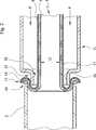
Der in der
Anhand der Schnittdarstellung der
Der Vorgang der Aushärtung des Polyesterharzes im Glasfasertextil
BezugszeichenlisteLIST OF REFERENCE NUMBERS
- 11
- Verbundschlauchcomposite hose
- 22
- Fluidleitungfluid line
- 33
- Glasfasertextilfiberglass fabric
- 44
- Foliefoil
- 55
- SchmelzkleberbeschichtungMelt adhesive coating
- 66
- Erhebungensurveys
- 77
- Überlappungsbereichoverlap area
- 88th
- Abschnitt der Innenoberfläche der FolieSection of the inner surface of the film
- 99
- Abschnitt der Außenoberfläche der FolieSection of the outer surface of the film
- 1010
- Öffnung der FluidleitungOpening the fluid line
- 1111
- InversiervorrichtungInversiervorrichtung
- 1212
- Innenhohlraum des VerbundschlauchesInner cavity of the composite tube
- 1313
- StülpbereichStülpbereich
- 1414
- Spannmittelclamping means
- 1515
- Flanschabschnittflange
- 1616
- Innenoberfläche des FlanscabschnittesInner surface of the Flanscabschnittes
- 1717
- Außenoberfläche des VerbundschlauchesOuter surface of the composite tube
- 1818
- Spaltabstandgap distance
- 1919
- UV-StrahlerUV lamps
- 2020
- Gestellframe
- 2121
- Rollkörperroll body
ZITATE ENTHALTEN IN DER BESCHREIBUNG QUOTES INCLUDE IN THE DESCRIPTION
Diese Liste der vom Anmelder aufgeführten Dokumente wurde automatisiert erzeugt und ist ausschließlich zur besseren Information des Lesers aufgenommen. Die Liste ist nicht Bestandteil der deutschen Patent- bzw. Gebrauchsmusteranmeldung. Das DPMA übernimmt keinerlei Haftung für etwaige Fehler oder Auslassungen.This list of the documents listed by the applicant has been generated automatically and is included solely for the better information of the reader. The list is not part of the German patent or utility model application. The DPMA assumes no liability for any errors or omissions.
Zitierte PatentliteraturCited patent literature
- EP 0875713 B1[0003, 0003]EP 0875713 B1[0003, 0003]
- DE 102010023764 A1[0004]DE 102010023764 A1[0004]
- DE 102012110265 A1[0005]DE 102012110265 A1[0005]
- DE 19852690 A1[0006]DE 19852690 A1[0006]
Claims (18)
Translated fromGermanPriority Applications (8)
| Application Number | Priority Date | Filing Date | Title |
|---|---|---|---|
| DE102015105668.2ADE102015105668C5 (en) | 2015-04-14 | 2015-04-14 | Composite hose for repairing leaky fluid lines, method for producing such a composite hose and method for repairing leaky fluid lines with a composite hose |
| CA2982626ACA2982626C (en) | 2015-04-14 | 2016-04-13 | Composite tube for repairing leaky fluid lines, method for producing such a composite tube and method for repairing leaky fluid lines with a composite tube |
| PCT/DE2016/100175WO2016165693A1 (en) | 2015-04-14 | 2016-04-13 | Composite tube for repairing leaky fluid lines, method for producing such a composite tube and method for repairing leaky fluid lines with a composite tube |
| CN201680034123.4ACN107743564B (en) | 2015-04-14 | 2016-04-13 | Composite pipe for repairing a leaking fluid line, method for producing such a composite pipe and method for repairing a leaking fluid line with a composite pipe |
| US15/566,388US10508764B2 (en) | 2015-04-14 | 2016-04-13 | Composite tube for repairing leaky fluid lines, method for producing such a composite tube and method for repairing leaky fluid lines with a composite tube |
| EP16724273.4AEP3283806B1 (en) | 2015-04-14 | 2016-04-13 | Composite tube for repairing leaky fluid lines, method for producing such a composite tube and method for repairing leaky fluid lines with a composite tube |
| RU2017134852ARU2689490C2 (en) | 2015-04-14 | 2016-04-13 | Composite hose for repair of loose pipelines of fluid medium, method of manufacturing such composite hose and method of repair of loose pipelines of fluid medium by means of composite hose |
| DK16724273.4TDK3283806T3 (en) | 2015-04-14 | 2016-04-13 | COMPOSITION HOSE FOR REPAIRING LEAKED FLUID PIPES, PROCEDURE FOR PREPARING SUCH A COMPOSITION HOSE, AND PROCEDURE FOR REPAIRING LEAKED FLUID PIPES WITH A COMPOSITION HOSE |
Applications Claiming Priority (1)
| Application Number | Priority Date | Filing Date | Title |
|---|---|---|---|
| DE102015105668.2ADE102015105668C5 (en) | 2015-04-14 | 2015-04-14 | Composite hose for repairing leaky fluid lines, method for producing such a composite hose and method for repairing leaky fluid lines with a composite hose |
Publications (3)
| Publication Number | Publication Date |
|---|---|
| DE102015105668A1true DE102015105668A1 (en) | 2016-10-20 |
| DE102015105668B4 DE102015105668B4 (en) | 2017-05-11 |
| DE102015105668C5 DE102015105668C5 (en) | 2020-07-09 |
Family
ID=56068571
Family Applications (1)
| Application Number | Title | Priority Date | Filing Date |
|---|---|---|---|
| DE102015105668.2AExpired - Fee RelatedDE102015105668C5 (en) | 2015-04-14 | 2015-04-14 | Composite hose for repairing leaky fluid lines, method for producing such a composite hose and method for repairing leaky fluid lines with a composite hose |
Country Status (8)
| Country | Link |
|---|---|
| US (1) | US10508764B2 (en) |
| EP (1) | EP3283806B1 (en) |
| CN (1) | CN107743564B (en) |
| CA (1) | CA2982626C (en) |
| DE (1) | DE102015105668C5 (en) |
| DK (1) | DK3283806T3 (en) |
| RU (1) | RU2689490C2 (en) |
| WO (1) | WO2016165693A1 (en) |
Families Citing this family (4)
| Publication number | Priority date | Publication date | Assignee | Title |
|---|---|---|---|---|
| CN110936597B (en)* | 2018-09-21 | 2022-10-18 | 哈尔滨工业大学 | Shape memory compensating pipe and shaping mould for manufacturing same |
| CN109237196A (en)* | 2018-10-19 | 2019-01-18 | 岭澳核电有限公司 | Pipeline lengthen the life layer, lengthen the life pipeline and pipeline is lengthened the life technique |
| CN113847505A (en)* | 2021-08-24 | 2021-12-28 | 江苏振祺建设工程有限公司 | Pipeline repair equipment based on upset inside lining technology |
| JP7422376B1 (en) | 2023-10-24 | 2024-01-26 | Meikou建設株式会社 | Piping lining device and piping lining method |
Citations (5)
| Publication number | Priority date | Publication date | Assignee | Title |
|---|---|---|---|---|
| DE19852690A1 (en) | 1998-11-16 | 2000-05-18 | Mueller Umwelttechnik | Method and device for the remediation of an old pipe run in the ground |
| EP0875713B1 (en) | 1997-05-02 | 2003-11-19 | Karl Otto Braun KG | Tubular lining material |
| DE102010023764A1 (en) | 2010-06-15 | 2011-12-15 | Huhtamaki Forchheim Zweigniederlassung Der Huhtamaki Deutschland Gmbh & Co. Kg | UV radiation permeable multilayer film |
| EP2573442A1 (en)* | 2011-09-23 | 2013-03-27 | Saertex multicom GmbH | Liner with internal coating |
| DE102012110265A1 (en) | 2012-10-26 | 2014-04-30 | Mondi Consumer Packaging International AG | Pipe interior coating material and method for the rehabilitation of defective sewers |
Family Cites Families (21)
| Publication number | Priority date | Publication date | Assignee | Title |
|---|---|---|---|---|
| FI88646C (en) | 1990-04-06 | 1993-06-17 | Suomen Putkisaneeraus Oy | Foerfarande och material Foer reparation av stroemningskanaler, saosom Roer |
| DE4238982C2 (en) | 1992-11-19 | 1997-03-13 | Kmg Kanal Mueller Gruppe Inter | Lining hose for the renovation of underground sewers, pipes or the like. |
| JP3790052B2 (en)* | 1998-09-25 | 2006-06-28 | 株式会社湘南合成樹脂製作所 | Manufacturing method of pipe lining material |
| DE19850227C1 (en)* | 1998-10-26 | 2000-06-21 | Siegfried Schwert | Hose for lining pipes |
| DE10042166A1 (en) | 2000-08-17 | 2002-03-07 | Siegfried Schwert | Method and hose for lining a high pressure pipeline |
| US6615875B2 (en) | 2000-08-30 | 2003-09-09 | Owens Corning Composites Sprl. | Liner for reinforcing a pipe and method of making the same |
| US20040163724A1 (en)* | 2001-09-06 | 2004-08-26 | Mark Trabbold | Formaldehyde-free duct liner |
| US20080277012A1 (en) | 2007-05-10 | 2008-11-13 | Anders Richard M | Reinforcing Liner |
| US8580364B2 (en) | 2008-09-19 | 2013-11-12 | Rene Quitter | Cured-in-place liner material and methods and systems for manufacture |
| US8118063B2 (en)* | 2009-02-26 | 2012-02-21 | Lmk Enterprises, Inc. | Method and apparatus for lining a pipe |
| JP5495250B2 (en)* | 2009-05-08 | 2014-05-21 | 株式会社湘南合成樹脂製作所 | Pipe lining material and pipe lining method |
| DE202009018745U1 (en)* | 2009-08-26 | 2013-02-01 | Lantor Gmbh | Foil composite for the inner lining of pipes |
| CN102466092A (en)* | 2010-11-02 | 2012-05-23 | 周永清 | High-pressure resistant glass fiber reinforced plastic enhanced steel-plastic composite pipe |
| DE102010051484A1 (en) | 2010-11-15 | 2012-05-16 | Brandenburger Patentverwertung Gbr (Vertretungsberechtigte Gesellschafter Herr Joachim Brandenburger, 82467 Garmisch-Partenkirchen; Herr Ludwig Allmann, 76857 Silz; Herr Wilhelm Leo Betz, 76887 Bad Bergzabern) | Casing lining hose and method and assembly for making same |
| DE102011103001B4 (en)* | 2011-05-24 | 2023-03-16 | Brandenburger Liner Gmbh & Co. Kg | Lining tube for the rehabilitation of defective sewers |
| US9429265B2 (en)* | 2012-04-12 | 2016-08-30 | Ashimori Industry Co., Ltd. | Lining method for conduit and lining material composite for conduit |
| DE202012104166U1 (en) | 2012-10-30 | 2012-11-23 | Trelleborg Pipe Seals Duisburg Gmbh | Lining element for rehabilitation of a pipeline |
| JP6030937B2 (en)* | 2012-12-07 | 2016-11-24 | 芦森工業株式会社 | Line lining material and line lining method |
| DE202014011441U1 (en) | 2013-03-11 | 2020-09-01 | Buergofol GmbH | Insertion hose for trenchless sewer rehabilitation |
| ES2922077T3 (en) | 2013-04-05 | 2022-09-07 | Buergofol GmbH | Method for lamination of a tubular film |
| DE102014111427A1 (en) | 2013-08-09 | 2015-02-12 | Buergofol GmbH | Film, in particular for use in trenchless sewer rehabilitation |
- 2015
- 2015-04-14DEDE102015105668.2Apatent/DE102015105668C5/ennot_activeExpired - Fee Related
- 2016
- 2016-04-13CNCN201680034123.4Apatent/CN107743564B/enactiveActive
- 2016-04-13RURU2017134852Apatent/RU2689490C2/enactive
- 2016-04-13EPEP16724273.4Apatent/EP3283806B1/enactiveActive
- 2016-04-13WOPCT/DE2016/100175patent/WO2016165693A1/ennot_activeCeased
- 2016-04-13DKDK16724273.4Tpatent/DK3283806T3/enactive
- 2016-04-13CACA2982626Apatent/CA2982626C/enactiveActive
- 2016-04-13USUS15/566,388patent/US10508764B2/enactiveActive
Patent Citations (5)
| Publication number | Priority date | Publication date | Assignee | Title |
|---|---|---|---|---|
| EP0875713B1 (en) | 1997-05-02 | 2003-11-19 | Karl Otto Braun KG | Tubular lining material |
| DE19852690A1 (en) | 1998-11-16 | 2000-05-18 | Mueller Umwelttechnik | Method and device for the remediation of an old pipe run in the ground |
| DE102010023764A1 (en) | 2010-06-15 | 2011-12-15 | Huhtamaki Forchheim Zweigniederlassung Der Huhtamaki Deutschland Gmbh & Co. Kg | UV radiation permeable multilayer film |
| EP2573442A1 (en)* | 2011-09-23 | 2013-03-27 | Saertex multicom GmbH | Liner with internal coating |
| DE102012110265A1 (en) | 2012-10-26 | 2014-04-30 | Mondi Consumer Packaging International AG | Pipe interior coating material and method for the rehabilitation of defective sewers |
Also Published As
| Publication number | Publication date |
|---|---|
| EP3283806A1 (en) | 2018-02-21 |
| WO2016165693A1 (en) | 2016-10-20 |
| US20180128413A1 (en) | 2018-05-10 |
| RU2017134852A3 (en) | 2019-05-14 |
| CN107743564B (en) | 2020-09-25 |
| RU2017134852A (en) | 2019-05-14 |
| CA2982626A1 (en) | 2016-10-20 |
| CA2982626C (en) | 2020-02-04 |
| CN107743564A (en) | 2018-02-27 |
| DE102015105668C5 (en) | 2020-07-09 |
| DK3283806T3 (en) | 2019-10-21 |
| RU2689490C2 (en) | 2019-05-28 |
| EP3283806B1 (en) | 2019-07-24 |
| DE102015105668B4 (en) | 2017-05-11 |
| US10508764B2 (en) | 2019-12-17 |
Similar Documents
| Publication | Publication Date | Title |
|---|---|---|
| EP2768655B1 (en) | Lining tube, renovated pressure pipe and method for renovating a pressure pipe | |
| DE69719223T2 (en) | THERMOPLASTIC COMPOSITE PRODUCTS AND METHOD FOR LINING A TUBE | |
| EP3283806B1 (en) | Composite tube for repairing leaky fluid lines, method for producing such a composite tube and method for repairing leaky fluid lines with a composite tube | |
| DE69111228T2 (en) | COATING MATERIALS FOR PIPELINES AND DUCTS. | |
| DE102013203840A1 (en) | Short liner for sewer rehabilitation | |
| DE202010017654U1 (en) | Lining material for sewer and / or piping and sewer and / or pipe lining | |
| EP3174703B1 (en) | Tubular liner for the rehabilitation of fluid-conducting pipeline systems | |
| DE102015013856A1 (en) | Sewer hose for sewer rehabilitation and method of making such | |
| EP2141404B1 (en) | A liner assembly for renovating a pipeline by using a liner and a transparent tape | |
| DE102015117372A1 (en) | Device for curing a lining hose | |
| DE102012015047A1 (en) | Lining hose having an inner film hose for lining pipelines and disposing for continuous production thereof | |
| EP3071872A1 (en) | Liner tube for renovating fluid-bearing pipe systems | |
| DE102014110930A1 (en) | Lining hose for refurbishment of fluid-carrying piping systems | |
| EP2141405B1 (en) | Method of renovating a pipeline by using a liner and a transparent tape | |
| EP3169508B1 (en) | Tube liner with a fleece-backed film web connected to form a film tube | |
| DE102020134200A1 (en) | LINER TUBE FOR REMEDIATION OF DEFECTIVE SEWER PIPES AND METHOD OF MANUFACTURE AND INSTALLATION OF SUCH | |
| DE102015212025A1 (en) | Pipe liner material for use for at least two predefined pipe sizes | |
| WO2019072900A1 (en) | METHOD AND ARRANGEMENT FOR RESTORING A LIQUID OR GASEOUS MEDIUM LEADING LINE | |
| DE19843358C1 (en) | Ground laid pipeline production by laying a flexible reinforced tube on the ground and curing the tube material | |
| EP3210771B1 (en) | Cladding tube for channelling and method for producing same | |
| DE202015103610U1 (en) | Versatile cone sleeve | |
| WO2024230898A1 (en) | Tubular liner comprising integrated sensors | |
| DE102004002578A1 (en) | In-situ lining of pipeline using thermally-hardened resin-impregnated flexible tubing, irradiates it at infra red wavelengths | |
| RU2529616C1 (en) | Lining hose to apply coating onto internal pipeline surface using liquid as heat carrier | |
| DE202014103321U1 (en) | Hose liner with a bonded to a film tube, fleece-laminated film web |
Legal Events
| Date | Code | Title | Description |
|---|---|---|---|
| R012 | Request for examination validly filed | ||
| R079 | Amendment of ipc main class | Free format text:PREVIOUS MAIN CLASS: F16L0055165000 Ipc:B32B0027080000 | |
| R079 | Amendment of ipc main class | Free format text:PREVIOUS MAIN CLASS: B32B0027080000 Ipc:B32B0027120000 | |
| R016 | Response to examination communication | ||
| R016 | Response to examination communication | ||
| R018 | Grant decision by examination section/examining division | ||
| R026 | Opposition filed against patent | ||
| R034 | Decision of examining division/federal patent court maintaining patent in limited form now final | ||
| R206 | Amended patent specification | ||
| R119 | Application deemed withdrawn, or ip right lapsed, due to non-payment of renewal fee |