DE102015103463A1 - Ball bearings, in particular conrod ball bearings, and connecting rods with a ball bearing - Google Patents
Ball bearings, in particular conrod ball bearings, and connecting rods with a ball bearingDownload PDFInfo
- Publication number
- DE102015103463A1 DE102015103463A1DE102015103463.8ADE102015103463ADE102015103463A1DE 102015103463 A1DE102015103463 A1DE 102015103463A1DE 102015103463 ADE102015103463 ADE 102015103463ADE 102015103463 A1DE102015103463 A1DE 102015103463A1
- Authority
- DE
- Germany
- Prior art keywords
- ball head
- ball
- connecting rod
- ball bearing
- retaining ring
- Prior art date
- Legal status (The legal status is an assumption and is not a legal conclusion. Google has not performed a legal analysis and makes no representation as to the accuracy of the status listed.)
- Withdrawn
Links
- 238000002485combustion reactionMethods0.000claimsdescription12
- 230000006835compressionEffects0.000claimsdescription12
- 238000007906compressionMethods0.000claimsdescription12
- 230000002349favourable effectEffects0.000description9
- 238000004519manufacturing processMethods0.000description4
- 239000002184metalSubstances0.000description4
- 238000005299abrasionMethods0.000description2
- BUHVIAUBTBOHAG-FOYDDCNASA-N(2r,3r,4s,5r)-2-[6-[[2-(3,5-dimethoxyphenyl)-2-(2-methylphenyl)ethyl]amino]purin-9-yl]-5-(hydroxymethyl)oxolane-3,4-diolChemical compoundCOC1=CC(OC)=CC(C(CNC=2C=3N=CN(C=3N=CN=2)[C@H]2[C@@H]([C@H](O)[C@@H](CO)O2)O)C=2C(=CC=CC=2)C)=C1BUHVIAUBTBOHAG-FOYDDCNASA-N0.000description1
- 230000009286beneficial effectEffects0.000description1
- 230000008092positive effectEffects0.000description1
- 230000036316preloadEffects0.000description1
Images


Classifications
- F—MECHANICAL ENGINEERING; LIGHTING; HEATING; WEAPONS; BLASTING
- F16—ENGINEERING ELEMENTS AND UNITS; GENERAL MEASURES FOR PRODUCING AND MAINTAINING EFFECTIVE FUNCTIONING OF MACHINES OR INSTALLATIONS; THERMAL INSULATION IN GENERAL
- F16C—SHAFTS; FLEXIBLE SHAFTS; ELEMENTS OR CRANKSHAFT MECHANISMS; ROTARY BODIES OTHER THAN GEARING ELEMENTS; BEARINGS
- F16C9/00—Bearings for crankshafts or connecting-rods; Attachment of connecting-rods
- F16C9/04—Connecting-rod bearings; Attachments thereof
- F—MECHANICAL ENGINEERING; LIGHTING; HEATING; WEAPONS; BLASTING
- F02—COMBUSTION ENGINES; HOT-GAS OR COMBUSTION-PRODUCT ENGINE PLANTS
- F02D—CONTROLLING COMBUSTION ENGINES
- F02D15/00—Varying compression ratio
- F02D15/02—Varying compression ratio by alteration or displacement of piston stroke
- F—MECHANICAL ENGINEERING; LIGHTING; HEATING; WEAPONS; BLASTING
- F02—COMBUSTION ENGINES; HOT-GAS OR COMBUSTION-PRODUCT ENGINE PLANTS
- F02B—INTERNAL-COMBUSTION PISTON ENGINES; COMBUSTION ENGINES IN GENERAL
- F02B75/00—Other engines
- F02B75/04—Engines with variable distances between pistons at top dead-centre positions and cylinder heads
- F02B75/045—Engines with variable distances between pistons at top dead-centre positions and cylinder heads by means of a variable connecting rod length
- F—MECHANICAL ENGINEERING; LIGHTING; HEATING; WEAPONS; BLASTING
- F16—ENGINEERING ELEMENTS AND UNITS; GENERAL MEASURES FOR PRODUCING AND MAINTAINING EFFECTIVE FUNCTIONING OF MACHINES OR INSTALLATIONS; THERMAL INSULATION IN GENERAL
- F16C—SHAFTS; FLEXIBLE SHAFTS; ELEMENTS OR CRANKSHAFT MECHANISMS; ROTARY BODIES OTHER THAN GEARING ELEMENTS; BEARINGS
- F16C11/00—Pivots; Pivotal connections
- F16C11/04—Pivotal connections
- F16C11/06—Ball-joints; Other joints having more than one degree of angular freedom, i.e. universal joints
- F16C11/0619—Ball-joints; Other joints having more than one degree of angular freedom, i.e. universal joints the female part comprising a blind socket receiving the male part
- F16C11/0623—Construction or details of the socket member
- F—MECHANICAL ENGINEERING; LIGHTING; HEATING; WEAPONS; BLASTING
- F16—ENGINEERING ELEMENTS AND UNITS; GENERAL MEASURES FOR PRODUCING AND MAINTAINING EFFECTIVE FUNCTIONING OF MACHINES OR INSTALLATIONS; THERMAL INSULATION IN GENERAL
- F16C—SHAFTS; FLEXIBLE SHAFTS; ELEMENTS OR CRANKSHAFT MECHANISMS; ROTARY BODIES OTHER THAN GEARING ELEMENTS; BEARINGS
- F16C11/00—Pivots; Pivotal connections
- F16C11/04—Pivotal connections
- F16C11/06—Ball-joints; Other joints having more than one degree of angular freedom, i.e. universal joints
- F16C11/0685—Manufacture of ball-joints and parts thereof, e.g. assembly of ball-joints
- F16C11/069—Manufacture of ball-joints and parts thereof, e.g. assembly of ball-joints with at least one separate part to retain the ball member in the socket; Quick-release systems
- F—MECHANICAL ENGINEERING; LIGHTING; HEATING; WEAPONS; BLASTING
- F16—ENGINEERING ELEMENTS AND UNITS; GENERAL MEASURES FOR PRODUCING AND MAINTAINING EFFECTIVE FUNCTIONING OF MACHINES OR INSTALLATIONS; THERMAL INSULATION IN GENERAL
- F16C—SHAFTS; FLEXIBLE SHAFTS; ELEMENTS OR CRANKSHAFT MECHANISMS; ROTARY BODIES OTHER THAN GEARING ELEMENTS; BEARINGS
- F16C11/00—Pivots; Pivotal connections
- F16C11/04—Pivotal connections
- F16C11/10—Arrangements for locking
- F16C11/103—Arrangements for locking frictionally clamped
- F16C11/106—Arrangements for locking frictionally clamped for ball joints
- F—MECHANICAL ENGINEERING; LIGHTING; HEATING; WEAPONS; BLASTING
- F16—ENGINEERING ELEMENTS AND UNITS; GENERAL MEASURES FOR PRODUCING AND MAINTAINING EFFECTIVE FUNCTIONING OF MACHINES OR INSTALLATIONS; THERMAL INSULATION IN GENERAL
- F16C—SHAFTS; FLEXIBLE SHAFTS; ELEMENTS OR CRANKSHAFT MECHANISMS; ROTARY BODIES OTHER THAN GEARING ELEMENTS; BEARINGS
- F16C7/00—Connecting-rods or like links pivoted at both ends; Construction of connecting-rod heads
- F16C7/06—Adjustable connecting-rods
- F—MECHANICAL ENGINEERING; LIGHTING; HEATING; WEAPONS; BLASTING
- F16—ENGINEERING ELEMENTS AND UNITS; GENERAL MEASURES FOR PRODUCING AND MAINTAINING EFFECTIVE FUNCTIONING OF MACHINES OR INSTALLATIONS; THERMAL INSULATION IN GENERAL
- F16J—PISTONS; CYLINDERS; SEALINGS
- F16J1/00—Pistons; Trunk pistons; Plungers
- F16J1/10—Connection to driving members
- F16J1/12—Connection to driving members with piston-rods, e.g. rigid connections
- F—MECHANICAL ENGINEERING; LIGHTING; HEATING; WEAPONS; BLASTING
- F16—ENGINEERING ELEMENTS AND UNITS; GENERAL MEASURES FOR PRODUCING AND MAINTAINING EFFECTIVE FUNCTIONING OF MACHINES OR INSTALLATIONS; THERMAL INSULATION IN GENERAL
- F16J—PISTONS; CYLINDERS; SEALINGS
- F16J1/00—Pistons; Trunk pistons; Plungers
- F16J1/10—Connection to driving members
- F16J1/14—Connection to driving members with connecting-rods, i.e. pivotal connections
- F16J1/22—Connection to driving members with connecting-rods, i.e. pivotal connections with universal joint, e.g. ball-joint
- F—MECHANICAL ENGINEERING; LIGHTING; HEATING; WEAPONS; BLASTING
- F16—ENGINEERING ELEMENTS AND UNITS; GENERAL MEASURES FOR PRODUCING AND MAINTAINING EFFECTIVE FUNCTIONING OF MACHINES OR INSTALLATIONS; THERMAL INSULATION IN GENERAL
- F16J—PISTONS; CYLINDERS; SEALINGS
- F16J7/00—Piston-rods
- F—MECHANICAL ENGINEERING; LIGHTING; HEATING; WEAPONS; BLASTING
- F16—ENGINEERING ELEMENTS AND UNITS; GENERAL MEASURES FOR PRODUCING AND MAINTAINING EFFECTIVE FUNCTIONING OF MACHINES OR INSTALLATIONS; THERMAL INSULATION IN GENERAL
- F16C—SHAFTS; FLEXIBLE SHAFTS; ELEMENTS OR CRANKSHAFT MECHANISMS; ROTARY BODIES OTHER THAN GEARING ELEMENTS; BEARINGS
- F16C23/00—Bearings for exclusively rotary movement adjustable for aligning or positioning
- F16C23/10—Bearings, parts of which are eccentrically adjustable with respect to each other
- F—MECHANICAL ENGINEERING; LIGHTING; HEATING; WEAPONS; BLASTING
- F16—ENGINEERING ELEMENTS AND UNITS; GENERAL MEASURES FOR PRODUCING AND MAINTAINING EFFECTIVE FUNCTIONING OF MACHINES OR INSTALLATIONS; THERMAL INSULATION IN GENERAL
- F16C—SHAFTS; FLEXIBLE SHAFTS; ELEMENTS OR CRANKSHAFT MECHANISMS; ROTARY BODIES OTHER THAN GEARING ELEMENTS; BEARINGS
- F16C2360/00—Engines or pumps
- F16C2360/22—Internal combustion engines
Landscapes
- Engineering & Computer Science (AREA)
- General Engineering & Computer Science (AREA)
- Mechanical Engineering (AREA)
- Chemical & Material Sciences (AREA)
- Combustion & Propulsion (AREA)
- Shafts, Cranks, Connecting Bars, And Related Bearings (AREA)
Abstract
Translated fromGermanDescription
Translated fromGermanTechnisches GebietTechnical area
Die Erfindung betrifft ein Kugellager sowie ein Pleuel mit einem Kugellager.The invention relates to a ball bearing and a connecting rod with a ball bearing.
Stand der TechnikState of the art
Bei Brennkraftmaschinen wirkt sich ein hohes Verdichtungsverhältnis positiv auf den Wirkungsgrad des Verbrennungsmotors aus. Unter Verdichtungsverhältnis wird im Allgemeinen das Verhältnis des gesamten Zylinderraumes vor der Verdichtung zum verbliebenen Zylinderraum nach der Verdichtung verstanden. Bei Brennkraftmaschinen mit Fremdzündung, insbesondere Ottomotoren, die ein festes Verdichtungsverhältnis aufweisen, darf das Verdichtungsverhältnis jedoch nur so hoch gewählt werden, dass bei Volllastbetrieb ein sogenanntes „Klopfen“ der Brennkraftmaschine vermieden wird. Jedoch könnte für den weitaus häufiger auftretenden Teillastbereich der Brennkraftmaschine, also bei geringer Zylinderfüllung, das Verdichtungsverhältnis mit höheren Werten gewählt werden, ohne dass ein „Klopfen“ auftreten würde. Der wichtige Teillastbereich einer Brennkraftmaschine kann verbessert werden, wenn das Verdichtungsverhältnis variabel einstellbar ist. Zur Verstellung des Verdichtungsverhältnisses sind beispielsweise Systeme mit variabler Pleuellänge bekannt.In internal combustion engines, a high compression ratio has a positive effect on the efficiency of the internal combustion engine. Under compression ratio is generally understood the ratio of the entire cylinder space before compression to the remaining cylinder space after compression. In internal combustion engines with spark ignition, in particular gasoline engines, which have a fixed compression ratio, however, the compression ratio may only be selected so high that a so-called "knocking" of the internal combustion engine is avoided at full load operation. However, for the much more frequently occurring partial load range of the internal combustion engine, that is to say with low cylinder filling, the compression ratio could be selected with higher values without "knocking" occurring. The important part load range of an internal combustion engine can be improved if the compression ratio is variably adjustable. For the adjustment of the compression ratio, for example, systems with variable connecting rod length are known.
Aus der
Offenbarung der ErfindungDisclosure of the invention
Eine Aufgabe der Erfindung ist es, ein hochbelastbares Kugellager mit einem in einer Kugelkopfaufnahme gelagerten Kugelkopf zu schaffen, das einfach zu montieren ist und hoch belastbar ist und Fertigungstoleranzen zulässt.An object of the invention is to provide a heavy-duty ball bearing with a ball head mounted in a ball bearing, which is easy to assemble and is highly resilient and allows manufacturing tolerances.
Eine weitere Aufgabe ist es, ein Pleuel mit einem solchen Kugellager anzugeben.Another object is to provide a connecting rod with such a ball bearing.
Die vorgenannten Aufgaben werden mit den Merkmalen der unabhängigen Ansprüche gelöst.The above objects are achieved with the features of the independent claims.
Günstige Ausgestaltungen und Vorteile der Erfindung ergeben sich aus den weiteren Ansprüchen, der Beschreibung und der Zeichnung.Favorable embodiments and advantages of the invention will become apparent from the other claims, the description and the drawings.
Es wird ein Kugellager mit einem an einer Stützstange angeordneten Kugelkopf vorgeschlagen, der in einer Kugelkopfaufnahme gelagert ist, wobei der Kugelkopf an seiner Außenfläche in der Kugelkopfaufnahme durch einen Sicherungsring gegen Herausgleiten aus der Kugelkopfaufnahme gesichert ist.It is proposed a ball bearing with a arranged on a support rod ball head, which is mounted in a ball head receptacle, wherein the ball head is secured on its outer surface in the ball head receptacle by a locking ring against sliding out of the ball head receptacle.
Der Sicherungsring kann einfach in die Kugelkopfaufnahme eingesetzt werden. Der Sicherungsring kann insbesondere entlang seiner Längsachse symmetrisch ausgebildet sein, so dass eine Montage verwechslungssicher erfolgen kann. Alternativ kann die Ausgestaltung auch unsymmetrisch sein. Vorteilhaft ist der Kugelkopf in der Kugelkopfaufnahme verschwenkbar und gleichzeitig axial nur mit hoher Auszugskraft aus der Kugelkopfaufnahme herausziehbar.The locking ring can be easily inserted into the ball head receptacle. The securing ring may be formed symmetrically, in particular along its longitudinal axis, so that a mounting can be carried out confusion. Alternatively, the embodiment may also be asymmetrical. Advantageously, the ball head is pivotable in the ball head receptacle and at the same time axially pulled out only with high pull-out force from the ball head receptacle.
Nach einer günstigen Ausgestaltung der Erfindung kann der Sicherungsring mit Vorspannung gegen eine Wand der Kugelkopfaufnahme gelegt sein. Durch die radiale Vorspannung ist bereits eine axiale Sicherung des Kugelkopfes möglich.According to a favorable embodiment of the invention, the retaining ring may be placed with bias against a wall of the ball head socket. Due to the radial preload an axial securing of the ball head is already possible.
Nach einer günstigen Ausgestaltung der Erfindung kann die Kugelkopfaufnahme an ihrem offenen Ende einen Hinterschnitt aufweisen, der den Sicherungsring in der Kugelkopfaufnahme axial sichert. Ein solcher Hinterschnitt ist fertigungstechnisch leicht herstellbar und bietet eine besonders hohe Sicherheit gegen ein Herausgleiten des Sicherungsrings und damit des Kugelkopfes aus der Kugelkopfaufnahme.According to a favorable embodiment of the invention, the ball head receptacle may have an undercut at its open end, which secures the circlip axially in the ball head receptacle. Such an undercut is easily produced in terms of production and offers a particularly high level of safety against sliding out of the securing ring and thus of the ball head from the ball head receptacle.
Nach einer günstigen Ausgestaltung der Erfindung kann die Kugelkopfaufnahme ein gewölbtes Bodenteil aufweisen, an das sich in axialer Richtung ein zylinderförmiger Raum anschließt. Das gewölbte Bodenteil ist in deren Kontaktbereich vorteilhaft an die Außenkontur des Kugelkopfes angepasst, so dass der Kugelkopf leicht verschwenkbar ist. Gleichzeitig bietet das gewölbte Bodenteil eine definierte Endlage des Kugelkopfs in axialer Richtung. Der gewölbte Bereich ist vorteilhafterweise etwa so tief wie der Radius des Kugelkopfes. Der zylinderförmige Raum bietet Platz zur Aufnahme des Sicherungsrings und ist im Durchmesser größer als der Kugelkopf.According to a favorable embodiment of the invention, the ball head receptacle may have a curved bottom part, to which a cylindrical space adjoins in the axial direction. The curved bottom part is advantageously adapted in the contact area to the outer contour of the ball head, so that the ball head is easily pivoted. At the same time, the curved bottom part offers a defined end position of the ball head in the axial direction. The arched area is advantageously about as deep as the radius of the ball head. The cylindrical space provides space for receiving the locking ring and is larger in diameter than the ball head.
Nach einer günstigen Ausgestaltung der Erfindung kann der Sicherungsring an seinem Umfang unterbrochen sein. Der Sicherungsring kann zur Montage mit einem geeigneten Werkzeug im Umfang verringert und in die Kugelkopfaufnahme eingeführt werden und daraufhin sich wieder im Umfang ausdehnen und an der Wand der Kugelkopfaufnahme radial vorgespannt anliegen. Dazu können die Innendurchmesser der Kugelkopfaufnahme im vorgesehenen Kontaktbereich mit dem Sicherungsring und der Außendurchmesser des Sicherungsrings geeignet aufeinander abgestimmt werden.According to a favorable embodiment of the invention, the retaining ring may be interrupted at its periphery. The circlip can be reduced for mounting with a suitable tool in the scope and introduced into the ball head receptacle and then expand again in the scope and bear against the wall of the ball head receiving radially biased. These can be the Inner diameter of the ball head receptacle in the intended contact area with the retaining ring and the outer diameter of the locking ring are suitably matched to each other.
Nach einer günstigen Ausgestaltung der Erfindung kann der Sicherungsring an seiner im eingebauten Zustand dem Kugelkopf zugewandten Stirnseite einen radial nach innen weisenden Bund aufweisen. Dies kann ein umgebördelter Rand sein, oder auch ein oder mehrere nach innen umgelegte Wandteile des Sicherungsrings. Der Sicherungsring kann beispielsweise ein Blechbiegeteil sein.According to a favorable embodiment of the invention, the securing ring may have a radially inwardly facing collar at its in the installed state the ball head facing end face. This may be a flanged edge, or one or more inwardly folded wall parts of the locking ring. The retaining ring may be, for example, a bent sheet metal part.
Nach einer günstigen Ausgestaltung der Erfindung kann der Sicherungsring radial nach innen eine Wölbung aufweisen. Mit besonderem Vorteil kann diese Wölbung symmetrisch zu einer Mitte einer Längsachse des Sicherungsrings ausgebildet sein. Dies erlaubt einen besonders abriebarmen Kontakt zwischen Sicherungsring und Kugelkopf, so dass auch erhöhte Reinheitsanforderungen erfüllt werden können.According to a favorable embodiment of the invention, the retaining ring may have a curvature radially inward. With particular advantage, this curvature can be formed symmetrically to a center of a longitudinal axis of the securing ring. This allows a particularly low-abrasion contact between circlip and ball head, so that even higher purity requirements can be met.
Nach einer günstigen Ausgestaltung der Erfindung kann der Sicherungsring aus Kunststoff gebildet sein. Der Kugelkopf kann vorteilhaft aus Metall sein. Die Paarung Metall/Kunststoff ist besonders günstig, um Abrieb zu vermeiden.According to a favorable embodiment of the invention, the retaining ring may be formed of plastic. The ball head may advantageously be made of metal. The pairing metal / plastic is particularly favorable to avoid abrasion.
Nach einem weiteren Aspekt der Erfindung wird ein Pleuel mit wenigstens einem Kugellager mit einem an einer Stützstange angeordneten Kugelkopf vorgeschlagen, wobei der Kugelkopf in einer Kugelkopfaufnahme gelagert ist, und wobei der Kugelkopf an seiner Außenfläche in der Kugelkopfaufnahme durch einen Sicherungsring gegen Herausgleiten aus der Kugelkopfaufnahme gesichert ist. Das Kugellager ist günstig herzustellen, einfach zu montieren und bietet eine hohe Auszugskraft gegen ein Herausziehen des Kugelkopfs aus der Kugelkopfaufnahme.According to a further aspect of the invention, a connecting rod with at least one ball bearing is proposed with a arranged on a support rod ball head, wherein the ball head is mounted in a ball head receptacle, and wherein the ball head secured on its outer surface in the ball head receptacle by a locking ring against slipping out of the ball head is. The ball bearing is inexpensive to manufacture, easy to assemble and offers a high pull-out force against pulling out of the ball head from the ball head.
Kurze Beschreibung der ZeichnungenBrief description of the drawings
Weitere Vorteile ergeben sich aus der folgenden Zeichnungsbeschreibung. In den Zeichnungen sind Ausführungsbeispiele der Erfindung dargestellt. Die Zeichnungen, die Beschreibung und die Ansprüche enthalten zahlreiche Merkmale in Kombination. Der Fachmann wird die Merkmale zweckmäßigerweise auch einzeln betrachten und zu sinnvollen weiteren Kombinationen zusammenfassen.Further advantages emerge from the following description of the drawing. In the drawings, embodiments of the invention are shown. The drawings, the description and the claims contain numerous features in combination. The person skilled in the art will expediently also consider the features individually and combine them into meaningful further combinations.
Es zeigen beispielhaft:They show by way of example:
Ausführungsformen der ErfindungEmbodiments of the invention
In den Figuren sind gleiche oder gleichartige Komponenten mit gleichen Bezugszeichen beziffert. Die Figuren zeigen lediglich Beispiele und sind nicht beschränkend zu verstehen.In the figures, the same or similar components are numbered with the same reference numerals. The figures are merely examples and are not intended to be limiting.
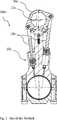
Das bekannte Pleuel
Das obere Pleuellagerauge
Die Kugelkopfaufnahme
Die Kugelkopfaufnahme
Der Sicherungsring
Der Sicherungsring
Die Kugelkopfaufnahme
Die Kugelkopfaufnahme
Der Sicherungsring
Der Sicherungsring
Das Kugellager
ZITATE ENTHALTEN IN DER BESCHREIBUNG QUOTES INCLUDE IN THE DESCRIPTION
Diese Liste der vom Anmelder aufgeführten Dokumente wurde automatisiert erzeugt und ist ausschließlich zur besseren Information des Lesers aufgenommen. Die Liste ist nicht Bestandteil der deutschen Patent- bzw. Gebrauchsmusteranmeldung. Das DPMA übernimmt keinerlei Haftung für etwaige Fehler oder Auslassungen.This list of the documents listed by the applicant has been generated automatically and is included solely for the better information of the reader. The list is not part of the German patent or utility model application. The DPMA assumes no liability for any errors or omissions.
Zitierte PatentliteraturCited patent literature
- DE 102005055199 A1[0003]DE 102005055199 A1[0003]
Claims (11)
Translated fromGermanPriority Applications (4)
| Application Number | Priority Date | Filing Date | Title |
|---|---|---|---|
| DE102015103463.8ADE102015103463A1 (en) | 2015-03-10 | 2015-03-10 | Ball bearings, in particular conrod ball bearings, and connecting rods with a ball bearing |
| US14/984,923US10018124B2 (en) | 2015-03-10 | 2015-12-30 | Ball bearing, in particular piston rod ball bearing and piston rod with ball bearing |
| EP16152498.8AEP3067576A1 (en) | 2015-03-10 | 2016-01-25 | Ball joint,particularly a ball joint for a connecting rod and a connecting rod with a ball joint |
| CN201610076101.6ACN105972058A (en) | 2015-03-10 | 2016-02-03 | Ball bearing, in particular connecting rod ball bearing and connecting rod with ball bearing |
Applications Claiming Priority (1)
| Application Number | Priority Date | Filing Date | Title |
|---|---|---|---|
| DE102015103463.8ADE102015103463A1 (en) | 2015-03-10 | 2015-03-10 | Ball bearings, in particular conrod ball bearings, and connecting rods with a ball bearing |
Publications (1)
| Publication Number | Publication Date |
|---|---|
| DE102015103463A1true DE102015103463A1 (en) | 2016-09-15 |
Family
ID=55262693
Family Applications (1)
| Application Number | Title | Priority Date | Filing Date |
|---|---|---|---|
| DE102015103463.8AWithdrawnDE102015103463A1 (en) | 2015-03-10 | 2015-03-10 | Ball bearings, in particular conrod ball bearings, and connecting rods with a ball bearing |
Country Status (4)
| Country | Link |
|---|---|
| US (1) | US10018124B2 (en) |
| EP (1) | EP3067576A1 (en) |
| CN (1) | CN105972058A (en) |
| DE (1) | DE102015103463A1 (en) |
Cited By (9)
| Publication number | Priority date | Publication date | Assignee | Title |
|---|---|---|---|---|
| DE102017109172A1 (en) | 2017-04-28 | 2018-10-31 | ECO Holding 1 GmbH | Connecting rod with a ball joint and method for producing a ball joint connection |
| EP3418533A1 (en) | 2017-06-23 | 2018-12-26 | ECO Holding 1 GmbH | Connecting rod for a combustion engine with variable compression |
| DE102018103387A1 (en) | 2017-06-23 | 2018-12-27 | ECO Holding 1 GmbH | Connecting rod for a variable compression internal combustion engine |
| DE102018107059A1 (en) | 2017-12-20 | 2019-06-27 | ECO Holding 1 GmbH | Connecting rod for a variable compression internal combustion engine |
| DE102019117463A1 (en) | 2019-06-28 | 2020-06-10 | ECO Holding 1 GmbH | Connecting rod for an internal combustion engine with variable compression and method for producing a connecting rod |
| DE102018131049A1 (en) | 2018-12-05 | 2020-06-10 | ECO Holding 1 GmbH | Ball joint and connecting rod with a ball joint |
| DE102019119187A1 (en) | 2019-07-16 | 2020-07-23 | ECO Holding 1 GmbH | Connecting rod for an internal combustion engine with variable compression |
| DE102021002183A1 (en) | 2021-04-24 | 2022-10-27 | Jan Grinbaum | Ball joint and method for its manufacture |
| DE202017007697U1 (en) | 2017-04-28 | 2024-07-15 | ECO Holding 1 GmbH | Connecting rod with a ball joint |
Families Citing this family (8)
| Publication number | Priority date | Publication date | Assignee | Title |
|---|---|---|---|---|
| DE102017113250A1 (en)* | 2016-12-21 | 2018-06-21 | ECO Holding 1 GmbH | Piston for a connecting rod and connecting rod |
| DE102017108982B4 (en) | 2017-04-26 | 2024-02-15 | Benteler Automobiltechnik Gmbh | Wheel handlebars with a ball joint |
| DE102017116122B3 (en) | 2017-07-18 | 2018-08-23 | Dr. Ing. H.C. F. Porsche Aktiengesellschaft | Method for producing a unit consisting of eccentric rod and piston of a connecting rod of an internal combustion engine |
| DE102017117028B4 (en) | 2017-07-27 | 2021-06-10 | Dr. Ing. H.C. F. Porsche Aktiengesellschaft | Connecting rod with eccentric adjusting device and combustion engine |
| CN109931159A (en)* | 2017-12-19 | 2019-06-25 | 伊希欧1控股有限公司 | The connecting rod with the eccentric wheel adjustment device for adjusting effective length of connecting rod of internal combustion engine |
| CN108266453A (en)* | 2018-03-19 | 2018-07-10 | 江苏可奈力机械制造有限公司 | A kind of novel link piston structure |
| DE102018115727B3 (en)* | 2018-06-29 | 2019-11-07 | Dr. Ing. H.C. F. Porsche Aktiengesellschaft | Supporting arrangement for an eccentric member of an adjustment arrangement and adjusting arrangement |
| AT522322B1 (en)* | 2019-05-15 | 2020-10-15 | Avl List Gmbh | Connecting rod with positive connection |
Citations (5)
| Publication number | Priority date | Publication date | Assignee | Title |
|---|---|---|---|---|
| DE2934218A1 (en)* | 1979-08-24 | 1981-03-19 | Alfred Teves Gmbh, 6000 Frankfurt | Thrust rod articulated joint - has plunger bore distorted inwards to secure ball head circlip |
| DE3607150A1 (en)* | 1986-03-05 | 1987-09-10 | Bosch Gmbh Robert | BALL JOINT |
| DE102005055199A1 (en) | 2005-11-19 | 2007-05-24 | Fev Motorentechnik Gmbh | Reciprocating internal combustion engine e.g. commercial vehicle diesel engine, has eccentric tappet moved along length of piston rod, where changeable resistor affects adjustment movement of tappet and effects adjustment movement of tappet |
| DE102008048515A1 (en)* | 2008-09-23 | 2010-03-25 | Schaeffler Kg | Angle joint for hydraulic valve tolerance compensation element of internal combustion engine, has safety ring axially held in joint socket by form-fit connection of joint head, where ring engages into undercut running into joint socket |
| DE112012001492T5 (en)* | 2011-03-31 | 2014-01-09 | Musashi Seimitsu Industry Co., Ltd. | Method for producing a ball joint |
Family Cites Families (21)
| Publication number | Priority date | Publication date | Assignee | Title |
|---|---|---|---|---|
| DE659600C (en) | 1936-05-24 | 1938-05-09 | Fritz Faudi | Ball joint |
| US2894548A (en) | 1956-01-09 | 1959-07-14 | Peck Rudolph | Clamp with interchangeable pressure pad |
| US2856250A (en) | 1957-02-13 | 1958-10-14 | Thoma Hans Johannes | Pistons and piston rods |
| GB900320A (en) | 1959-03-06 | 1962-07-04 | Wilton Tool Mfg Co Inc | Improvements in clamps or the like for holding work pieces |
| US3107505A (en)* | 1961-02-15 | 1963-10-22 | Hague Mfg Company | Universal joint |
| DE2757198A1 (en) | 1977-12-22 | 1979-06-28 | Ehrenreich Gmbh & Co Kg A | BALL JOINT |
| JPS6138315U (en) | 1984-08-13 | 1986-03-10 | 株式会社 ニフコ | ball joint |
| US4666330A (en)* | 1985-12-04 | 1987-05-19 | Tuthill Corporation | Ball joint assembly |
| DE3607149A1 (en) | 1986-03-05 | 1987-09-10 | Bosch Gmbh Robert | BALL JOINT |
| US5247873A (en) | 1992-01-28 | 1993-09-28 | Cooper Industries, Inc. | Connecting rod assembly with a crosshead |
| US5153976A (en) | 1992-03-23 | 1992-10-13 | Allied-Signal Inc. | Ball-and-socket assembly and method of making |
| DE29702140U1 (en) | 1997-02-08 | 1997-04-03 | Demmeler Maschinenbau GmbH, 87751 Heimertingen | Clamping tool |
| DE29713483U1 (en) | 1997-07-29 | 1998-01-08 | Kleinbongartz & Kaiser Werkzeugfabrik, 42853 Remscheid | Screw clamp |
| DE19752076A1 (en)* | 1997-11-25 | 1999-05-27 | Schaeffler Waelzlager Ohg | Piston rod fastening on piston of master cylinder |
| EP1617472A1 (en) | 2004-07-16 | 2006-01-18 | Axalto SA | An active protection device for protecting a circuit against mechanical and electromagnetic attack |
| DE602005020067D1 (en)* | 2005-04-08 | 2010-04-29 | Federal Mogul Corp | COMPRESSION LOAD BALL JOINT WITH PARTITIONED METAL BEARING |
| DE102006052254B4 (en)* | 2006-11-03 | 2012-12-20 | Zf Friedrichshafen Ag | ball joint |
| US8511265B2 (en)* | 2009-06-01 | 2013-08-20 | Steven Don Arnold | Variable stroke and compression ratio engine |
| DE102011002592A1 (en) | 2011-01-12 | 2012-07-12 | Schaeffler Technologies Gmbh & Co. Kg | angle joint |
| WO2014099374A1 (en)* | 2012-12-21 | 2014-06-26 | Borgwarner Inc. | Variable compression ratio piston system |
| DE102013224270B3 (en)* | 2013-11-27 | 2015-01-08 | Schaeffler Technologies Gmbh & Co. Kg | Device for changing the compression ratio of a cylinder unit of a reciprocating internal combustion engine |
- 2015
- 2015-03-10DEDE102015103463.8Apatent/DE102015103463A1/ennot_activeWithdrawn
- 2015-12-30USUS14/984,923patent/US10018124B2/ennot_activeExpired - Fee Related
- 2016
- 2016-01-25EPEP16152498.8Apatent/EP3067576A1/ennot_activeWithdrawn
- 2016-02-03CNCN201610076101.6Apatent/CN105972058A/enactivePending
Patent Citations (5)
| Publication number | Priority date | Publication date | Assignee | Title |
|---|---|---|---|---|
| DE2934218A1 (en)* | 1979-08-24 | 1981-03-19 | Alfred Teves Gmbh, 6000 Frankfurt | Thrust rod articulated joint - has plunger bore distorted inwards to secure ball head circlip |
| DE3607150A1 (en)* | 1986-03-05 | 1987-09-10 | Bosch Gmbh Robert | BALL JOINT |
| DE102005055199A1 (en) | 2005-11-19 | 2007-05-24 | Fev Motorentechnik Gmbh | Reciprocating internal combustion engine e.g. commercial vehicle diesel engine, has eccentric tappet moved along length of piston rod, where changeable resistor affects adjustment movement of tappet and effects adjustment movement of tappet |
| DE102008048515A1 (en)* | 2008-09-23 | 2010-03-25 | Schaeffler Kg | Angle joint for hydraulic valve tolerance compensation element of internal combustion engine, has safety ring axially held in joint socket by form-fit connection of joint head, where ring engages into undercut running into joint socket |
| DE112012001492T5 (en)* | 2011-03-31 | 2014-01-09 | Musashi Seimitsu Industry Co., Ltd. | Method for producing a ball joint |
Cited By (12)
| Publication number | Priority date | Publication date | Assignee | Title |
|---|---|---|---|---|
| DE102017109172A1 (en) | 2017-04-28 | 2018-10-31 | ECO Holding 1 GmbH | Connecting rod with a ball joint and method for producing a ball joint connection |
| DE202017007697U1 (en) | 2017-04-28 | 2024-07-15 | ECO Holding 1 GmbH | Connecting rod with a ball joint |
| EP3418533A1 (en) | 2017-06-23 | 2018-12-26 | ECO Holding 1 GmbH | Connecting rod for a combustion engine with variable compression |
| DE102018103387A1 (en) | 2017-06-23 | 2018-12-27 | ECO Holding 1 GmbH | Connecting rod for a variable compression internal combustion engine |
| US10655535B2 (en) | 2017-06-23 | 2020-05-19 | ECO Holding 1 GmbH | Connecting rod for an internal combustion engine with variable compression |
| DE102018107059A1 (en) | 2017-12-20 | 2019-06-27 | ECO Holding 1 GmbH | Connecting rod for a variable compression internal combustion engine |
| DE102018131049A1 (en) | 2018-12-05 | 2020-06-10 | ECO Holding 1 GmbH | Ball joint and connecting rod with a ball joint |
| DE102019117463A1 (en) | 2019-06-28 | 2020-06-10 | ECO Holding 1 GmbH | Connecting rod for an internal combustion engine with variable compression and method for producing a connecting rod |
| CN112145541A (en)* | 2019-06-28 | 2020-12-29 | 伊希欧1控股有限公司 | Connecting rod for an internal combustion engine with variable compression and method for producing a connecting rod |
| DE102019119187A1 (en) | 2019-07-16 | 2020-07-23 | ECO Holding 1 GmbH | Connecting rod for an internal combustion engine with variable compression |
| DE102021002183A1 (en) | 2021-04-24 | 2022-10-27 | Jan Grinbaum | Ball joint and method for its manufacture |
| DE102021002183B4 (en) | 2021-04-24 | 2023-06-07 | Jan Grinbaum | Ball joint and method for its manufacture |
Also Published As
| Publication number | Publication date |
|---|---|
| CN105972058A (en) | 2016-09-28 |
| EP3067576A1 (en) | 2016-09-14 |
| US10018124B2 (en) | 2018-07-10 |
| US20160265448A1 (en) | 2016-09-15 |
Similar Documents
| Publication | Publication Date | Title |
|---|---|---|
| DE102015103463A1 (en) | Ball bearings, in particular conrod ball bearings, and connecting rods with a ball bearing | |
| DE102010005606A1 (en) | Cam follower for actuating a gas exchange valve | |
| DE102015109924A1 (en) | Piston for a connecting rod and connecting rod | |
| DE102014218961A1 (en) | Roller tappet and method of manufacturing a housing member of a roller tappet | |
| EP3268641B1 (en) | Connecting rod with a ball and socket joint | |
| DE102017124274B3 (en) | Built roller pestle | |
| EP1920174B1 (en) | Piston-pin bore dimensions for a piston of an internal combustion engine | |
| DE102015109580A1 (en) | Insert and connecting rod for a variable compression of an internal combustion engine | |
| DE102017113250A1 (en) | Piston for a connecting rod and connecting rod | |
| DE102018119419A1 (en) | Connecting rods for an internal combustion engine with an eccentric adjustment device for adjusting an effective connecting rod length | |
| DE102016114984A1 (en) | Ball bearing and connecting rod with a ball bearing | |
| DE102019119854A1 (en) | Connecting rod for an internal combustion engine with variable compression | |
| DE102016208907A1 (en) | Arc-shaped thrust washer for a cylinder crankcase of a reciprocating internal combustion engine | |
| DE102014112074A1 (en) | transmission element | |
| EP3008318A1 (en) | Slide shoe for a piston for use in internal combustion engines | |
| DE102019117463A1 (en) | Connecting rod for an internal combustion engine with variable compression and method for producing a connecting rod | |
| DE102013211279A1 (en) | Cup tappets for the valve train of an internal combustion engine | |
| DE102018107057A1 (en) | Connecting rod for a variable compression internal combustion engine | |
| DE102018203417A1 (en) | Piston arrangement of an internal combustion engine | |
| EP3274574B1 (en) | Connecting rod with shaft-hub connection | |
| DE102019120480A1 (en) | Connecting rod for an internal combustion engine with variable compression | |
| DE102019118760A1 (en) | Connecting rod of an internal combustion engine with variable compression | |
| DE102019114173A1 (en) | Connecting rod of an internal combustion engine with variable compression | |
| DE102019121423A1 (en) | Connecting rod for an internal combustion engine with variable compression | |
| DE102015204321A1 (en) | High-pressure fuel pump, in particular for a fuel injection device of an internal combustion engine |
Legal Events
| Date | Code | Title | Description |
|---|---|---|---|
| R163 | Identified publications notified | ||
| R119 | Application deemed withdrawn, or ip right lapsed, due to non-payment of renewal fee |