Movatterモバイル変換


[0]ホーム

URL:


DE102015000912B4 - Bicycle chainring - Google Patents

Bicycle chainring
Download PDF

Info

Publication number
DE102015000912B4
DE102015000912B4DE102015000912.5ADE102015000912ADE102015000912B4DE 102015000912 B4DE102015000912 B4DE 102015000912B4DE 102015000912 ADE102015000912 ADE 102015000912ADE 102015000912 B4DE102015000912 B4DE 102015000912B4
Authority
DE
Germany
Prior art keywords
tooth
chain
axial direction
teeth
distance
Prior art date
Legal status (The legal status is an assumption and is not a legal conclusion. Google has not performed a legal analysis and makes no representation as to the accuracy of the status listed.)
Active
Application number
DE102015000912.5A
Other languages
German (de)
Other versions
DE102015000912A1 (en
Inventor
Yusuke Nishimoto
Mitsuru Kamiya
Current Assignee (The listed assignees may be inaccurate. Google has not performed a legal analysis and makes no representation or warranty as to the accuracy of the list.)
Shimano Inc
Original Assignee
Shimano Inc
Priority date (The priority date is an assumption and is not a legal conclusion. Google has not performed a legal analysis and makes no representation as to the accuracy of the date listed.)
Filing date
Publication date
Priority claimed from US14/446,930external-prioritypatent/US10000256B2/en
Application filed by Shimano IncfiledCriticalShimano Inc
Publication of DE102015000912A1publicationCriticalpatent/DE102015000912A1/en
Application grantedgrantedCritical
Publication of DE102015000912B4publicationCriticalpatent/DE102015000912B4/en
Activelegal-statusCriticalCurrent
Anticipated expirationlegal-statusCritical

Links

Images

Classifications

Landscapes

Abstract

Translated fromGerman

Fahrradritzel (10), in Eingriff bringbar mit einer Rollen (40a) aufweisenden Kette (40), das Ritzel (10) umfassend:einen Körper (12), drehbar herum um eine Rotationsmittelachse (X); und zumindest einen Zahnabschnitt (14, 214, 314, 414), bereitgestellt entlang einem peripheren Abschnitt des Körpers (12) und aufweisend eine Vorderfläche (20, 520a, 520b), eine Rückfläche (22, 522b), welche weg weist von der Vorderfläche (20, 520a, 520b) in der axialen Richtung der Rotationsmittelachse (X), eine Antriebsseitenfläche (24, 124, 424, 524b, 524d), welche die Vorder- und Rückflächen (20, 520a, 520b, 22, 522b) miteinander in der axialen Richtung auf einer nachgelagerten Seite in Bezug auf eine Antriebsdrehrichtung (R1) verbindet und eine nicht-antriebs-Seitenfläche, welche die Vorder- und Rückflächen (20, 520a, 520b, 22, 522b) miteinander in der axialen Richtung auf einer vorgelagerten Seite in Bezug auf die Antriebsdrehrichtung (R1) verbindet, wobei der zumindest eine Zahnabschnitt (14, 214, 314, 414) so konfiguriert ist, dass eine von den Vorder- und Rückflächen (20, 520a, 520b, 22, 522b) einen ersten geschrägten Abschnitt (32) aufweist, welcher in einer radialen äußeren Abschnitt des zumindest einen Zahnabschnitts (14, 214, 314, 414) ausgeformt ist und sich radial auswärts in der axialen Richtung verjüngt und bei dem der Zahnabschnitt (14, 214, 314, 414) eine Gruppe einer Vielzahl von ersten Zähnen (514d) und eine Gruppe einer Vielzahl von zweiten Zähnen (514e) aufweist, jeder der ersten Zähne (514d) aufweisend eine erste Ketteneingriffsweite (T1) in der axialen Richtung und jeder der zweiten Zähne (514e) aufweisend eine zweite Ketteneingriffsweite (T2) in der axialen Richtung und die zweite Ketteneingriffsweite (T2) größer ist, als die erste Ketteneingriffsweite (T1) und die Gesamtanzahl der Zähne (114) in dem Zahnabschnitt (14, 214, 314, 414) eine gerade Anzahl ist, unddie Antriebsseitenfläche (24, 124, 424, 524b, 524d) einen ersten Vorsprung (28, 428, 528a, 528b) aufweist, welcher nachgelagert in der Antriebsdrehrichtung (R1) hervorsteht und radial auswärts von einer Kontaktposition (CP) angeordnet ist, in welcher die Antriebsseitenfläche (24, 124, 424, 524b, 524d) in Kontakt mit einer jeden der Rollen (40a) kommt, wenn die Kette (40) angetrieben wird, wobei die Antriebsseitenfläche (24, 124, 424, 524b, 524d) einen Abschnitt aufweist, befindlich radial nach außen des ersten Vorsprungs (28, 428, 528a, 528b) und ausgeformt an einer gebogenen Fläche, welche konvex in Bezug auf den ersten Vorsprung (28, 428, 528a, 528b) gekrümmt ist.Bicycle sprocket (10) engageable with a chain (40) having rollers (40a), the sprocket (10) comprising:a body (12) rotatable about a center axis of rotation (X); and at least one tooth portion (14, 214, 314, 414) provided along a peripheral portion of the body (12) and having a front surface (20, 520a, 520b), a back surface (22, 522b) facing away from the front surface (20, 520a, 520b) in the axial direction of the rotation center axis (X), a drive side surface (24, 124, 424, 524b, 524d) which connects the front and rear surfaces (20, 520a, 520b, 22, 522b) with each other the axial direction on a downstream side with respect to a driving rotation direction (R1), and a non-driving side surface connecting the front and rear surfaces (20, 520a, 520b, 22, 522b) with each other in the axial direction on an upstream side with respect to the driving direction of rotation (R1), wherein the at least one tooth portion (14, 214, 314, 414) is configured such that one of the front and rear surfaces (20, 520a, 520b, 22, 522b) has a first bevel Section (32) which is formed in a radial outer section of the at least one tooth section (14, 214, 314, 414) and tapers radially outwards in the axial direction and in which the tooth section (14, 214, 314, 414) a group of a plurality of first teeth (514d) and a group of a plurality of second teeth (514e), each of the first teeth (514d) having a first chain meshing width (T1) in the axial direction and each of the second teeth (514e). a second chain engagement width (T2) in the axial direction and the second chain engagement width (T2) is larger than the first chain engagement width (T1) and the total number of teeth (114) in the tooth section (14, 214, 314, 414) is an even number is, and the drive side surface (24, 124, 424, 524b, 524d) has a first projection (28, 428, 528a, 528b) which protrudes downstream in the drive rotation direction (R1) and is arranged radially outward from a contact position (CP), in which the drive side surface (24, 124, 424, 524b, 524d) comes into contact with each of the rollers (40a) when the chain (40) is driven, the drive side surface (24, 124, 424, 524b, 524d) a portion located radially outward of the first projection (28, 428, 528a, 528b) and formed on a curved surface which is convexly curved with respect to the first projection (28, 428, 528a, 528b).

Description

Translated fromGerman

Hintergrundbackground

Technisches GebietTechnical area

Diese Anmeldung beansprucht die Priorität der U.S. Anmeldung Nr.US 61/930,542, welche am 23. Januar 2014 eingereicht wurde undUS 14/446,930, welche am 30. Juli 2014 eingereicht wurde. Auf die gesamte Offenbarung der U.S. Anmeldungen61/930,542 undUS 14/446,930 wird hierbei in Gänze Bezug genommen.This application claims priority to US Application No. US 61/930,542 , which was filed on January 23, 2014 and US 14/446,930 , which was filed on July 30, 2014. To the entire disclosure of the US applications 61/930,542 and US 14/446,930 is referred to in its entirety.

Die vorliegende Erfindung bezieht sich auf ein Kettenblatt bzw. Ritzel, insbesondere auf ein Fahrradkettenblatt bzw. Fahrradritzel, welches in Eingriff mit einer Kette gebracht werden kann, die Rollen hat.The present invention relates to a chainring or sprocket, in particular to a bicycle chainring or sprocket, which can be brought into engagement with a chain having rollers.

Technologischer HintergrundTechnological background

Bei einem Fahrrad, welches mit einer Vielzahl von hinteren Ritzeln bzw. Kettenblättern bereitgestellt ist, wird ein Gangwechsel unter Verwendung eines hinteren Umwerfers durchgeführt. Fährt ein Fahrer auf solch einem Fahrrad durch raues Terrain, verursachen Bodenunebenheiten ein Vibrieren bzw. Schwingen der Kettenführung des hinteren Umwerfers ähnlich einem Pendel, was die auf die Kette wirkende Spannung ändert. Es ist zu bevorzugen, dass eine Änderung der auf die Kette wirkenden Spannung unwahrscheinlich dazu führt, dass die Kette von dem vorderen Kettenblatt bzw. Ritzel außer Eingriff gebracht wird.In a bicycle provided with a plurality of rear sprockets, gear changing is performed using a rear derailleur. When a rider rides such a bike through rough terrain, uneven ground causes the chain guide of the rear derailleur to vibrate or swing like a pendulum, which changes the tension on the chain. It is preferable that a change in the tension acting on the chain is unlikely to cause the chain to become disengaged from the front sprocket.

Das DokumentEP 0 522 984 A1 offenbart ein Kettenrad für ein Kettengetriebe, das eine Folge von Zähnen umfasst, die radial durch einen vorderen Rand und einen hinteren Rand begrenzt sind, die dazu bestimmt sind, sich an den entsprechenden Rollen der Kettenglieder abzustützen, dadurch gekennzeichnet, dass der vordere Rand durch eine konkave Krümmung gebildet ist, die sich beiderseits des Teilkreises erstreckt, um sich nach außen über diesen hinaus zu erstrecken und so einen Rückhaltehaken zu bilden.The document EP 0 522 984 A1 discloses a sprocket for a chain transmission comprising a series of teeth radially delimited by a front edge and a rear edge intended to rest on the corresponding rollers of the chain links, characterized in that the front edge is formed by a concave curvature is formed, which extends on both sides of the pitch circle to extend outwards beyond it and so form a retaining hook.

Das DokumentEP 0 269 557 A1 offenbart ein Kettenrad mit Taschen zur Aufnahme von Horizontalgliedern einer Rundstahlkette. Für die Aufnahme von den Horizontalgliedern finden Zähne Verwendung, an deren Zahnfußrundungen sich Schrägflächen anschließen, die zur Abstützung der Horizontalglieder von Ketten dienen, deren Teilung größer als die Teilung des Kettenrades ist.The document EP 0 269 557 A1 discloses a chain wheel with pockets for holding horizontal links of a round steel chain. Teeth are used to accommodate the horizontal links, the tooth base curves of which are adjoined by inclined surfaces which serve to support the horizontal links of chains whose pitch is greater than the pitch of the chain wheel.

Das DokumentUS 2013 / 0 139 642 A1 offenbart ein Ritzel, welches eine Vielzahl von ersten Zähnen aufweist und eine gleiche Anzahl von zweiten Zähnen, die länger in Richtung der Drehachse des Kettenblatts bzw. Ritzels sind, als die ersten Zähne ist, was bedeutet dass diese dicker sind als die ersten Zähne, wobei die ersten und zweiten Zähne abwechselnd angeordnet sind. Bei dieser Konfiguration greifen die ersten Zähne in Gliedplatten der Kette mit engen Innenweiten der inneren Gliedplatten ein und die zweiten Zähnen greifen mit Gliedplatten der Kette ein mit breiten Innenweiten der inneren Gliedplatten, was in einer erhöhten Kettenhaltekraft zu Folge hat, wodurch es unwahrscheinlicher ist, dass die Kette außer Eingriff von dem Ritzel bzw. Kettenblatt gelangt, wenn auf einem rauen Terrain gefahren wird. Weiterhin hat bei dem Ritzel bzw. Kettenblatt des Standes der Technik eine Seitenfläche auf der vorgelagerten Seite in der Richtung, in welche das Ritzel bzw. Kettenblatt angetrieben und gedreht wird, welche eine nicht-antriebs-Seitenfläche ist, mit welcher die Rollen der Kette nicht in Kontakt kommen, eine Form, welche in der umfänglichen Richtung hervorsteht. Diese Form erhöht weiterhin die Kettenhaltekraft.The document US 2013 / 0 139 642 A1 discloses a sprocket which has a plurality of first teeth and an equal number of second teeth which are longer in the direction of the axis of rotation of the chainring or sprocket than the first teeth, which means that they are thicker than the first teeth, wherein the first and second teeth are arranged alternately. In this configuration, the first teeth engage chain link plates with narrow inner link plate inner widths and the second teeth engage chain link plates with wide inner link plate inner widths, resulting in increased chain holding force, making it less likely The chain becomes disengaged from the sprocket or chainring when riding on rough terrain. Furthermore, the prior art sprocket has a side surface on the upstream side in the direction in which the sprocket is driven and rotated, which is a non-drive side surface with which the rollers of the chain do not operate come into contact, a shape which protrudes in the circumferential direction. This shape further increases the chain holding power.

DE 10 2010 023 882 A1 offenbart ein mehrteiliges Kettenrad, bei dem ein Innenring zur Befestigung des mehrteiligen Kettenrades an einer Radnabe Durchgangslöcher aufweist, welche auf einem gemeinsamen Lochkreis liegen, wobei der Innenring zur Aufnahme eines Zahnkranzes an seiner Peripherie Innenring-Ansätze aufweist, welche radial nach außen weisen, und dass der Zahnkranz radial nach innen weisende Zahnkranz-Ansätze aufweist, welche den radial nach außen weisenden Innenring-Ansätzen des Innenrings räumlich zugeordnet sind, und dass Mittel vorhanden sind, welche den Innenring und den Zahnkranz axial und radial miteinander verbinden.DE 10 2010 023 882 A1 discloses a multi-part sprocket, in which an inner ring for fastening the multi-part sprocket to a wheel hub has through holes which lie on a common hole circle, the inner ring having inner ring lugs on its periphery for receiving a sprocket, which point radially outwards, and that the gear rim has radially inward-pointing gear rim lugs which are spatially assigned to the radially outward-pointing inner ring lugs of the inner ring, and that means are present which connect the inner ring and the gear rim to one another axially and radially.

Überblick über die ErfindungOverview of the invention

Das Kettenblatt bzw. Ritzel des Standes der Technik, welches die ersten und zweiten Zähne aufweist, mit voneinander unterschiedlicher Dicke und alternierend angeordnet, bietet eine erhöhte Kettenhaltekraft. Die Idee einer unterschiedlichen Dicke ist jedoch nur auf ein Ritzel bzw. Kettenblatt anwendbar, welches eine gerade Gesamtanzahl von Zähnen hat und ist nicht anwendbar auf ein Ritzel bzw. Kettenblatt, welches eine ungerade Gesamtanzahl von Zähnen hat.The prior art chainring or sprocket, which has the first and second teeth having different thicknesses from each other and arranged alternately, provides increased chain holding force. However, the idea of different thickness is only applicable to a sprocket or chainring that has an even total number of teeth and is not applicable to a sprocket or chainring that has an odd total number of teeth.

Eine Aufgabe der vorliegenden Erfindung, ist es ein Fahrradkettenblatt bzw. Ritzel bereitzustellen, welches eine erhöhte Kettenhaltekraft bereitstellt (das bedeutet eine Kraft basierend auf welcher das Kettenblatt bzw. Ritzel die Kette hält) ohne alternierend einen Unterschied in der Dicke der Zahnabschnitte des Ritzels zu haben.An object of the present invention is to provide a bicycle chainring or sprocket which provides increased chain holding force (that is, a force based on which the chainring or sprocket holds the chain) without having an alternating difference in the thickness of the tooth portions of the sprocket .

Ein Fahrradritzel bzw. Kettenblatt gemäß einem Aspekt der Erfindung ist in Eingriff bringbar mit einer Rollen aufweisenden Kette. Das Fahrradritzel bzw. - kettenblatt weist einen Körper und zumindest einen Zahnabschnitt auf. Der Körper ist drehbar herum um eine Rotationsmittelachse. Der zumindest eine Zahnabschnitt ist entlang eines peripheren Abschnitts des Körpers bereitgestellt und hat eine Vorderfläche, eine Rückfläche, welche in einer axialen Richtung der Rotationsmittelachse weg weist von der Vorderfläche, eine Antriebsseitenfläche, welche die Vorder- und Rückflächen miteinander in der axialen Richtung einer nachgelagerten Seite in Bezug auf eine Antriebsdrehrichtung verbindet und eine nicht-antriebs-Seitenfläche, welche die Vorder- und Rückflächen miteinander in der axialen Richtung auf einer vorgelagerten Seite in Bezug auf die Antriebsdrehrichtung verbindet.A bicycle sprocket or chainring according to one aspect of the invention is engageable with a chain having rollers. The bicycle sprocket or chainring has a body and at least one tooth section. The body is rotatable about a center axis of rotation. The at least one tooth portion is provided along a peripheral portion of the body and has a front surface, a rear surface facing away from the front surface in an axial direction of the rotation center axis, a drive side surface connecting the front and rear surfaces together in the axial direction of a downstream side with respect to a drive rotation direction, and a non-drive side surface that connects the front and rear surfaces with each other in the axial direction on an upstream side with respect to the drive rotation direction.

Der zumindest eine Zahnabschnitt hat einen ersten geschrägten Abschnitt an einem radial äußeren Abschnitt von einem von der Vorderfläche und der Rückfläche und der erste geschrägte Abschnitt ist so geformt, dass er sich radial auswärts in der axialen Richtung verjüngt. Die Antriebsseitenfläche hat einen ersten Vorsprung, welcher nachgelagert in der Antriebsdrehrichtung hervorsteht und radial auswärts von einer Kontaktposition angeordnet ist, an welcher die Antriebsseitenfläche in Kontakt mit jeder der Rollen kommt, wenn die Kette angetrieben wird. Die Antriebsseitenfläche weist einen Abschnitt auf, befindlich radial nach außen des ersten Vorsprungs und ausgeformt an einer gebogenen Fläche, welche konvex in Bezug auf den ersten Vorsprung gekrümmt ist.The at least one tooth portion has a first tapered portion at a radially outer portion of one of the front surface and the rear surface, and the first tapered portion is shaped to taper radially outward in the axial direction. The drive side surface has a first projection projecting downstream in the drive rotation direction and disposed radially outward from a contact position at which the drive side surface comes into contact with each of the rollers when the chain is driven. The drive side surface has a portion located radially outward of the first projection and formed on a curved surface that is convexly curved with respect to the first projection.

Bei dem Ritzel ist der erste Vorsprung, welcher in der Antriebsdrehrichtung nach unten erstreckt oder nachgelagert angeordnet ist, radial auswärts bereitgestellt von einer Position, in der die Rolle in Kontakt mit der Antriebsseitenfläche kommt. Der erste Vorsprung begrenzt somit die Bewegung von jeder der Rollen der Kette, welche in Kontakt mit der Antriebsseitenfläche kommen, wobei es unwahrscheinlich ist, dass sich die Rollen radial auswärts bewegen. Die oben stehende Konfiguration erlaubt eine Erhöhung der Kettenhaltekraft ohne abwechselnde und in der axialen Weite voneinander abweichende der Vielzahl von Zahnabschnitte. Sowohl Ritzel bzw. Kettenblätter, welche eine gerade Gesamtanzahl von Zähnen haben und Ritzel bzw. Kettenblätter, welche eine ungerade Gesamtanzahl von Zähnen haben, können daher mit einer erhöhten Kettenhaltekraft bereitgestellt werden. Weiterhin kann, nachdem eine der Vorderfläche und der Rückfläche den ersten geschrägten Abschnitt, welcher sich verjüngt und in einem radial äußeren Abschnitt des zumindest einen Zahnabschnitts geformt ist hat, sich das in der Antriebsrichtung drehende Ritzel einfacher mit der Kette in Eingriff gelangen, wenn der erste Vorsprung bereitgestellt ist, um die Kettenhaltekraft zu verbessern.In the pinion, the first projection, which extends downward or is disposed downstream in the driving rotation direction, is provided radially outward from a position in which the roller comes into contact with the driving side surface. The first projection thus limits the movement of each of the rollers of the chain coming into contact with the drive side surface, making the rollers unlikely to move radially outward. The above configuration allows the chain holding force to be increased without alternating the plurality of tooth sections and differing in axial width. Both sprockets or chainrings that have an even total number of teeth and sprockets or chainrings that have an odd total number of teeth can therefore be provided with an increased chain holding force. Furthermore, after one of the front surface and the rear surface has the first tapered portion which is tapered and formed in a radially outer portion of the at least one tooth portion, the pinion rotating in the driving direction can more easily engage with the chain when the first Projection is provided to improve the chain holding force.

Bevorzugt steht der erste Vorsprung nachgelagert in der Antriebsdrehrichtung von der Kontaktposition hervor, in welcher die Antriebsseitenfläche in Kontakt mit jeder der Rollen kommt, wenn die Kette angetrieben wird, um einen ersten Abstand, der nicht größer oder gleich 0,1 mm ist, jedoch kleiner oder gleich 0,5 mm ist. Diese Konfiguration erlaubt es dem Zahnabschnitt des Ritzels einfach in Eingriff mit der Kette zu gelangen und verhindert, dass die Kette, welche mit dem Ritzel in Eingriff steht, sich von diesem leicht löst.Preferably, the first projection protrudes downstream in the drive rotation direction from the contact position in which the drive side surface comes into contact with each of the rollers when the chain is driven, by a first distance not greater than or equal to 0.1 mm, but smaller or equal to 0.5 mm. This configuration allows the tooth portion of the sprocket to easily come into engagement with the chain and prevents the chain, which is engaged with the sprocket, from easily disengaging therefrom.

Der erste Abstand kann größer oder gleich 0,2 mm sein, jedoch kleiner oder gleich 0,3 mm.The first distance can be greater than or equal to 0.2 mm but less than or equal to 0.3 mm.

Der erste Abstand kann 0,2 mm sein.The first distance can be 0.2 mm.

Bevorzugt hat die nicht-antriebs-Seitenfläche einen Erhebungsabschnitt bzw. erhabenen Abschnitt, der konvex in einer umfänglichen Richtung hin zu der nachgelagerten Seite in Bezug auf die Antriebsdrehrichtung ist und der Erhebungsabschnitt steht um eine Größenordnung hervor, welche kleiner ist als eine Größenordnung, um die der erste Vorsprung hervorsteht. In diesem Falle erhält das Bereitstellen des Erhebungsabschnitts die Freigängigkeit des Eingriffs zwischen dem Zahnabschnitt und er Kette und hindert effektiv die Kette daran, außer Eingriff von dem Zahnabschnitt zu gelangen.Preferably, the non-drive side surface has a raised portion that is convex in a circumferential direction toward the downstream side with respect to the driving rotation direction, and the raised portion protrudes by an order of magnitude smaller than an order of magnitude the first projection protrudes. In this case, providing the raised portion maintains the freedom of engagement between the tooth portion and the chain and effectively prevents the chain from disengaging from the tooth portion.

Die nicht-antriebs-Seitenfläche kann einen zweiten Vorsprung haben, welcher in einer umfänglichen Richtung hervorsteht. Die Bereitstellung des zweiten Vorsprungs begrenzt eine radiale Auswärtsbewegung einer jeder der Rollen ebenso auf der nicht-antriebs-Seitenfläche, wodurch die Kettenhaltekraft weiter erhöht wird.The non-drive side surface may have a second projection that protrudes in a circumferential direction. Providing the second projection limits radial outward movement of each of the rollers on the non-drive side surface as well, thereby further increasing the chain holding force.

Bevorzugt kann eine gerade Linie, welche eine Kontaktposition, in der jede der Rollen in Kontakt mit der Antriebsseitenflächen kommt wenn die Kette angetrieben wird, mit der Rotationsmittelachse verbindet zusammen mit einer Tangentiallinie zu der Antriebsseitenfläche in der Kontaktposition einen Winkel bildet, der kleiner oder gleich 7 Grad ist. In diesem Falle ist es unwahrscheinlich, dass sich die Rollen radial auswärts an der Antriebsseitenfläche bewegen, wodurch es unwahrscheinlich ist, dass die Kette außer Eingriff mit dem Ritzel gelangt.Preferably, a straight line connecting a contact position in which each of the rollers comes into contact with the drive side surface when the chain is driven with the rotation center axis, together with a line tangential to the drive side surface in the contact position, may form an angle less than or equal to 7 degree is. In this case, the rollers are unlikely to move radially outward on the drive side surface, making the chain unlikely to disengage from the sprocket.

Ein Fahrradritzel gemäß einem weiteren Aspekt der Erfindung ist in Eingriff bringbar mit einer Rollen aufweisenden Kette. Das Fahrradritzel weist einen Körper und zumindest einen Zahnabschnitt auf. Der Körper ist drehbar herum um eine Rotationsmittelachse. Der zumindest eine Zahnabschnitt ist bereitgestellt entlang eines peripheren Abschnitt des Körpers und hat eine Vorderfläche, eine Rückfläche, welche in einer axialen Richtung weg weist von der Vorderfläche der Rotationsmittelachse, eine Antriebsseitenfläche, welche auf einer nachgelagerten Seite einer Antriebsrotationsfläche die Vorderfläche und die Rückfläche miteinander in der axialen Richtung verbindet und eine nicht-antriebs-Seitenfläche, welche auf einer vorgelagerten Seite in Bezug auf die Antriebsdrehrichtung die Vorderfläche und die Rückfläche miteinander in der axialen Richtung verbindet.A bicycle sprocket according to a further aspect of the invention is engageable with a chain having rollers. The bicycle pinion has a body and at least one tooth section. The body is rotatable about a center axis of rotation. The at least one tooth section is provided along a peripheral Section of the body and has a front surface, a rear surface which faces in an axial direction away from the front surface of the rotation center axis, a drive side surface which, on a downstream side of a drive rotation surface, connects the front surface and the rear surface to each other in the axial direction, and a non-drive -Side surface which connects the front surface and the rear surface to one another in the axial direction on an upstream side with respect to the driving direction of rotation.

Der zumindest eine Zahnabschnitt hat einen ersten geschrägten Abschnitt an einem radial äußeren Abschnitt von einem von der Vorderfläche oder der Rückfläche und der erste geschrägte Abschnitt ist so geformt, dass er sich nach radial auswärts in der axialen Richtung verjüngt. Eine gerade Linie, welche eine Kontaktposition, in welcher jede der Rollen in Kontakt mit der Antriebsseitenfläche kommt wenn die Kette angetrieben wird, mit der Rotationsmittelachse verbindet, zusammen mit einer Tangentiallinie zu der Antriebsseitenfläche in der Kontaktposition einen Winkel bildet, der kleiner oder gleich 7 Grad ist.The at least one tooth portion has a first tapered portion at a radially outer portion of one of the front surface and the back surface, and the first tapered portion is shaped to taper radially outward in the axial direction. A straight line connecting a contact position in which each of the rollers comes into contact with the drive side surface when the chain is driven to the rotation center axis, together with a tangent line to the drive side surface in the contact position, forms an angle less than or equal to 7 degrees is.

Bei dem Fahrradritzel ist es unwahrscheinlich, dass sich die Rollen radial auswärts an der Antriebsseitenfläche des Zahnabschnitts bewegen, wodurch es unwahrscheinlich ist, dass die Kette außer Eingriff mit dem Ritzel bzw. Kettenblatt gelangt. Weiterhin erlaubt die oben stehend beschriebene Konfiguration eine Erhöhung der Kettenhaltekraft, ohne die ihrer axialen Dicke alternierenden der Vielzahl von Zahnabschnitten.In the bicycle sprocket, the rollers are unlikely to move radially outward on the drive side surface of the sprocket, making the chain unlikely to disengage from the sprocket. Furthermore, the configuration described above allows the chain holding force to be increased without alternating the plurality of tooth sections in their axial thickness.

Bevorzugt kann der Winkel kleiner oder gleich 3 Grad sein.The angle can preferably be less than or equal to 3 degrees.

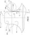
Der Zahnabschnitt kann einen ersten Zahn, einen zweiten Zahn und einen dritten Zahn hat, wobei der zweite Zahn benachbart zu dem ersten Zahn ist und vorgelagert zu dem ersten Zahn in der Antriebsdrehrichtung, und wobei der dritte Zahn benachbart zu dem zweiten Zahn ist und vorgelagert zu dem zweiten Zahn in der Antriebsdrehrichtung und eine Kontaktposition, in welcher jede der Rollen die Antriebsseitenfläche des ersten Zahns berührt wenn die Kette angetrieben wird, ist von einer nachgelagerten Spitzenposition beabstandet, die eine Position, einer Spitze des dritten Zahns auf einer am Weitesten nachgelagerten Seite in Bezug auf die Antriebsdrehrichtung ist, um einen zweiten Abstand, der größer oder gleich ist 25,4 mm, jedoch kleiner oder gleich 27 mm ist.The tooth portion may have a first tooth, a second tooth and a third tooth, the second tooth being adjacent to and upstream of the first tooth in the drive rotation direction, and wherein the third tooth is adjacent to and upstream of the second tooth the second tooth in the driving rotation direction and a contact position in which each of the rollers contacts the driving side surface of the first tooth when the chain is driven is spaced from a downstream tip position, which is a position of a tip of the third tooth on a most downstream side in Reference to the drive direction of rotation is by a second distance which is greater than or equal to 25.4 mm but less than or equal to 27 mm.

In diesem Fall ist ein Grenzabstand, welcher eine Referenz ist, die dazu verwendet wird ob oder nicht der dritte Zahn des sich drehenden Ritzels mit der Kette in Eingriff gelangt (Abstand zwischen erstem Zahn und dritten Zahn) zwei Mal so groß, wie die Intervalle zwischen den Rollen der Kette (typischerweise 12,7 mm), wodurch die Kette auf eine verlässliche Art und Weise leicht gefangen bzw. in Eingriff gelangt wird.In this case, a limit distance, which is a reference used to determine whether or not the third tooth of the rotating sprocket engages the chain (distance between first tooth and third tooth) is twice the intervals between the rollers of the chain (typically 12.7 mm), which easily catches or engages the chain in a reliable manner.

Der zweite Abstand kann größer oder gleich 25,4mm sein, jedoch kleiner oder gleich 26,6mm.The second distance can be greater than or equal to 25.4mm but less than or equal to 26.6mm.

Die andere von der Vorderfläche und der Rückfläche kann einen zweiten geschrägten Abschnitt aufweisen, welcher in einem radialen äußeren Abschnitt des zumindest einen Zahnabschnitts geformt ist und sich radial nach außen in der axialen Richtung verjüngt. In diesem Fall kann, weil ein geschrägter Abschnitt an jeder der Vorder- und Rückseiten bereitgestellt ist, die Kette leichter in Eingriff mit dem Zahnabschnitt des Ritzels gelangen. Die vordere Fläche kann den ersten geschrägten Abschnitt aufweisen und die hintere Fläche kann den zweiten geschrägten Abschnitt aufweisen.The other of the front surface and the rear surface may include a second tapered portion formed in a radially outer portion of the at least one tooth portion and tapering radially outwardly in the axial direction. In this case, because a tapered portion is provided at each of the front and rear sides, the chain can be more easily engaged with the tooth portion of the sprocket. The front surface may include the first tapered portion and the rear surface may include the second tapered portion.

Bevorzugt ist ein radial äußeres peripheres Ende des ersten geschrägten Abschnitts um einen dritten Abstand in der axialen Richtung beabstandet von einem radial inneren peripheren Ende des ersten geschrägten Abschnitts und ein radial äu-ßeres peripheres Ende des zweiten geschrägten Abschnitts ist von einem radial inneren peripheren Ende des zweiten geschrägten Abschnitts um einen vierten Abstand in der axialen Richtung beabstandet, der gleich dem dritten Abstand ist. In diesem Falle ist es unwahrscheinlich, dass die Kette außer Eingriff von dem Zahnabschnitt gelangt, selbst wenn die Kette in axialer Richtung schwingt, nachdem die axialen Abstände des ersten geschrägten Abschnitts und des zweiten geschrägten Abschnitts zueinander gleich sind.Preferably, a radially outer peripheral end of the first tapered section is spaced a third distance in the axial direction from a radially inner peripheral end of the first tapered section and a radially outer peripheral end of the second tapered section is spaced from a radially inner peripheral end of the second tapered portion is spaced apart by a fourth distance in the axial direction which is equal to the third distance. In this case, the chain is unlikely to come out of engagement with the toothed portion even if the chain swings in the axial direction after the axial distances of the first tapered portion and the second tapered portion are equal to each other.

Bei einer alternativen bevorzugten Ausführungsform ist ein radial äußeres peripheres Ende des ersten geschrägten Abschnitts um einen dritten Abstand in der axialen Richtung beabstandet von einem radial inneren peripheren Ende des ersten geschrägten Abschnitts und ein radial äußeres peripheres Ende des zweiten geschrägten Abschnitts ist um einen vierten Abstand in der axialen Richtung beabstandet von einem radial inneren peripheren Ende des zweiten geschrägten Abschnitts, wobei der vierte Abstand unterschiedlich ist von dem dritten Abstand.In an alternative preferred embodiment, a radially outer peripheral end of the first tapered section is spaced a third distance in the axial direction from a radially inner peripheral end of the first tapered section and a radially outer peripheral end of the second tapered section is spaced a fourth distance in the axial direction spaced from a radially inner peripheral end of the second tapered portion, the fourth distance being different from the third distance.

Der dritte Abstand kann größer sein als der vierte Abstand. In diesem Fall ist, nachdem der erste geschrägte Abschnitt an der Vorderfläche des Ritzels tiefer ist, als der zweite geschrägte Abschnitt, welcher in der hinteren Fläche des Ritzels ausgeformt ist, die Extremspitze des Zahnabschnitts des Ritzels näher an der hinteren Fläche positioniert. Wenn das Ritzel gemäß der Erfindung ein vorderes Ritzel bzw. Kettenblatt ist und die Kette somit von dem hinteren Ritzel hin zu dem vorderen Ritzel bzw. Kettenblatt so gesetzt ist, dass diese schief nach außen in der axialen Richtung angestellt ist bzw. verläuft, gelangt die Kette leicht mit dem vorderen Ritzel bzw. Kettenblatt in Eingriff.The third distance can be greater than the fourth distance. In this case, since the first tapered portion on the front surface of the pinion is deeper than the second tapered portion formed in the rear surface of the pinion, the extreme tip of the tooth portion of the pinion is positioned closer to the rear surface. If the pinion according to the invention is a front one sprocket or chainring and the chain is thus set from the rear sprocket to the front sprocket or chainring in such a way that it is tilted outwards in the axial direction, the chain easily gets along with the front sprocket or chainring. Chainring engaged.

Bevorzugt weist der Zahnabschnitt eine Gruppe einer Vielzahl von ersten Zähnen und eine Gruppe einer Vielzahl von zweiten Zähnen auf, wobei jeder der ersten Zähne eine erste Ketteneingriffsweite in der axialen Richtung hat, jeder der zweiten Zähne eine zweite Ketteneingriffsweite in der axialen Richtung hat, welche größer ist als die erste Weite und die Gesamtanzahl der Zähne in dem Zahnabschnitt eine gerade Anzahl ist. In diesem Falle ist die Weite eines jeden der ersten Zähne festgelegt in Übereinstimmung mit der Lücke zwischen einem Paar der inneren Kettenglieder der Kette und die Weite eines jeden der zweiten Zähne ist in Übereinstimmung mit der Lücke zwischen einem Paar von äußeren Gliedern der Kette gesetzt, wodurch die Kettenhaltekraft weiter erhöht wird.Preferably, the tooth section has a group of a plurality of first teeth and a group of a plurality of second teeth, each of the first teeth having a first chain engagement width in the axial direction, each of the second teeth having a second chain engagement width in the axial direction, which is larger is than the first width and the total number of teeth in the tooth section is an even number. In this case, the width of each of the first teeth is set in accordance with the gap between a pair of the inner links of the chain and the width of each of the second teeth is set in accordance with the gap between a pair of the outer links of the chain, whereby the chain holding force is further increased.

Die ersten Ketteneingriffsweite eines jeden der ersten Zähne kann eine Weite sein, welche einen Eingriff mit den inneren Gliedplatten der Kette erlaubt und die zweite Ketteneingriffsweite eines jeden der zweiten Zähne kann eine Weite sein, welche einen Eingriff mit den äußeren Gliedplatten der Kette erlaubt.The first chain engagement width of each of the first teeth may be a width that allows engagement with the inner link plates of the chain and the second chain engagement width of each of the second teeth may be a width that allows engagement with the outer link plates of the chain.

Die Gruppe der ersten Zähne und die Gruppe der zweiten Zähne kann alternierend angeordnet sein in einer umfänglichen Richtung.The group of first teeth and the group of second teeth may be arranged alternately in a circumferential direction.

Der Zahnabschnitt kann durch ein Stapelelement geformt werden, welches drei aufeinander gestapelte Lagen in der axialen Richtung aufweist. In diesem Fall erlaubt die Verwendung eines leichten Materials zur Bildung der Mittellage des Stapelelements, die nicht in Kontakt mit der Kette gelangt, eine Gewichtsreduzierung des Ritzels bzw. Kettenblattes.The tooth portion may be formed by a stacking member having three layers stacked one on top of the other in the axial direction. In this case, the use of a light material to form the central layer of the stacking element, which does not come into contact with the chain, allows a reduction in the weight of the sprocket or chainring.

Das Stapelelement kann ein erstes Element aufweisen, welches aus einem ersten metallischen Material gefertigt ist, ein zweites Element aufweisen, welches aus einem zweiten metallischen Material gefertigt und ein drittes Element aufweisen, das zwischen dem ersten Element und dem zweiten Element in der axialen Richtung angeordnet und aus einem dritten metallischen Material gefertigt ist und wobei eine spezifische Dichte des dritten metallischen Material geringer ist, als eine spezifische Dichte eines jeden der ersten und zweiten metallischen Materialien. In diesem Falle erlaubt es das zwischen dem ersten Element und dem zweiten Element angeordnete dritte Elemente, dass das Gewicht des Ritzels bzw. Kettenblattes reduziert wird.The stacking member may include a first member made of a first metallic material, a second member made of a second metallic material, and a third member disposed between the first member and the second member in the axial direction and is made of a third metallic material and wherein a specific gravity of the third metallic material is less than a specific gravity of each of the first and second metallic materials. In this case, the third element arranged between the first element and the second element allows the weight of the sprocket or chainring to be reduced.

Jedes der ersten und zweiten metallischen Materialien kann Stahl sein und das dritte metallische Material kann Aluminium sein.Each of the first and second metallic materials may be steel and the third metallic material may be aluminum.

Das Stapelelement kann ein erstes Element aufweisen, welches aus einem ersten metallischen Material ist, ein zweites Element aufweisen, welches aus einem zweiten metallischen Material gefertigt und ein drittes Element aufweisen, welches aus einem nicht metallischen Material gefertigt ist. In diesem Falle wird das dritte Element, welches aus einem nicht metallischen Material gefertigt und zwischen dem ersten und dem zweiten Element angeordnet ist, erlauben, das Gewicht des Ritzels zu reduzieren.The stacking element may comprise a first element made of a first metallic material, a second element made of a second metallic material and a third element made of a non-metallic material. In this case, the third element, made of a non-metallic material and arranged between the first and second elements, will allow to reduce the weight of the pinion.

Das nicht metallische Material kann Kunststoff enthalten.The non-metallic material may contain plastic.

Kurze Beschreibung der ZeichnungenBrief description of the drawings

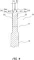
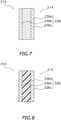
  • 1 ist eine Seitenansicht eines Ritzels gemäß einer ersten Ausführungsform der Erfindung.1 is a side view of a pinion according to a first embodiment of the invention.
  • 2 ist eine vergrößerte Kantenansicht des Ritzels.2 is an enlarged edge view of the pinion.
  • 3 ist eine Seitenansicht eines Zahnabschnitts des Ritzels.3 is a side view of a tooth portion of the pinion.
  • 4 ist eine Querschnittsansicht eines Ritzels, gesehen entlang einer Schnittlinie IV-IV in1.4 is a cross-sectional view of a pinion gear seen along section line IV-IV in 1 .
  • 5 ist eine Teilseitenansicht des Ritzels und beschreibt einen Grenzabstand.5 is a partial side view of the pinion and describes a limit distance.
  • 6 zeigt ein Ritzel gemäß einer zweiten Ausführungsform der Erfindung und entspricht2.6 shows a pinion according to a second embodiment of the invention and corresponds 2 .
  • 7 ist eine diagrammartige Querschnittsansicht des Ritzels gemäß der Variation 1.7 is a diagrammatic cross-sectional view of the pinion according tovariation 1.
  • 8 ist eine diagrammartige Querschnittsansicht eines Ritzels gemäß der Variation 2.8th is a diagrammatic cross-sectional view of a pinion according to Variation 2.
  • 9 zeigt ein Ritzel gemäß der Variation 3 und entspricht3.9 shows a pinion according to variation 3 and corresponds 3 .
  • 10 zeigt ein Ritzel gemäß Variation 4 und entspricht2.10 shows a pinion according to variation 4 and corresponds 2 .
  • 11 zeigt ein Ritzel gemäß Variation 5 und entspricht4.11 shows a pinion according to variation 5 and corresponds 4 .

Bevorzugte Ausführungsformen der ErfindungPreferred embodiments of the invention

Ausgewählte Ausführungsformen werden nun unter Bezugnahme auf die Zeichnungen erklärt. Es ist dem Fachmann auf dem Gebiete der Fahrradtechnik von dieser Offenbarung ersichtlich, dass die folgenden gegebenen Beschreibungen der Ausführungsformen nur zu Illustrationszwecken allein und nicht zum Zwecke der Begrenzung der Erfindung, wie diese durch die beigefügten Ansprüche und deren Äquivalente definiert ist, gegeben wird.Selected embodiments will now be explained with reference to the drawings. It is for the expert in the field of bicycles As is apparent from this disclosure, the following descriptions of the embodiments are provided for illustrative purposes only and not for the purpose of limiting the invention as defined by the appended claims and their equivalents.

(Erste Ausführungsform)(First embodiment)

Ein Ritzel 10 gemäß einer ersten Ausführungsform der Erfindung ist ein Fahrradritzel bzw. Kettenblatt, welches in Eingriff bringbar ist mit einer Rollen 40a aufweisenden Kette 40, wie gezeigt in1 und2. Das Ritzel 10 ist ein Beispiel eines Fahrradritzels bzw. Kettenblattes. Das Ritzel 10 wird zum Beispiel als vorderes Kettenrad eines Fahrrades verwendet. Wenn an ein Fahrrad montiert, ist das Ritzel 10 typischerweise in einer Position angeordnet, welche mit leicht mehr Abstand von dem Fahrrad angeordnet ist, als eine axiale Mittelposition einer hinteren Ritzelanordnung, die durch eine Vielzahl von hinteren Ritzeln bzw. Kettenblättern geformt wird. Die Kette 40 weist Rollen 40a, eine Vielzahl von Paaren von linken und rechten inneren Gliedplatten 40b und eine Vielzahl von Paaren von äußeren Gliedplatten 40c auf, welche an die Außenseitenflächen der inneren Gliedplatten 40b verbunden sind, wie zu sehen in4. Die Vielzahl von inneren Gliedplatten 40b sind schwenkbar mit den äußeren Gliedplatten 40c durch Verbindungsstifte 40d verbunden. Jede der Rollen 40a ist drehbar herum um eine äußere umfängliche Fläche des entsprechenden Verbindungsstifts 40d befestigt. Nachdem die Kette 40 eine bekannte Fahrradkette ist, wird keine detaillierte Beschreibung der Kette 40 gegeben.Asprocket 10 according to a first embodiment of the invention is a bicycle sprocket or chainring which is engageable with achain 40 havingrollers 40a, as shown in FIG 1 and 2 . Thepinion 10 is an example of a bicycle pinion or chainring. Thepinion 10 is used, for example, as the front sprocket of a bicycle. When mounted to a bicycle, thesprocket 10 is typically disposed in a position slightly further away from the bicycle than an axially center position of a rear sprocket assembly formed by a plurality of rear sprockets. Thechain 40 includesrollers 40a, a plurality of pairs of left and rightinner link plates 40b, and a plurality of pairs ofouter link plates 40c connected to the outside surfaces of theinner link plates 40b, as shown in FIG 4 . The plurality ofinner link plates 40b are pivotally connected to theouter link plates 40c through connectingpins 40d. Each of therollers 40a is rotatably mounted around an outer peripheral surface of the corresponding connectingpin 40d. Since thechain 40 is a well-known bicycle chain, no detailed description of thechain 40 will be given.

Das Ritzel 10 weist einen Körper 12 auf, welcher drehbar herum um eine Rotationsmittelachse X ist und zumindest einen Zahnabschnitt 14, welcher entlang eines peripheren Abschnitts des Körpers 12 bereit gestellt wird, wie zu sehen in1 und2. Der Körper ist aus einem ringförmigen Plattenelement gefertigt, welches zum Beispiel aus Stahl, Aluminium, Titan oder einem anderen metallischen Material oder einem carbonfaserverstärkten Material oder einem anderen nicht metallischen Material hergestellt ist. Der Körper 12 hat eine Vielzahl von Kurbelbefestigungsabschnitten 12a, welche in einem radial inneren Abschnitt ausgeformt sind und die Kurbelbefestigungsabschnitte 12 sind an einem Kurbelarm (nicht gezeigt) zum Beispiel mit einer Vielzahl von Schraubenelementen befestigt. In der ersten Ausführungsform ist der Körper 12 dicker als der Zahnabschnitt 14 der axialen Richtung des Körpers 12. Der Körper kann jedoch gleich dick wie der Zahnabschnitt sein.Thepinion 10 includes abody 12 rotatable about a rotation center axis X and at least onetooth portion 14 provided along a peripheral portion of thebody 12, as seen in FIG 1 and 2 . The body is made of an annular plate member made, for example, of steel, aluminum, titanium or another metallic material or a carbon fiber reinforced material or another non-metallic material. Thebody 12 has a plurality ofcrank attachment portions 12a formed in a radially inner portion, and thecrank attachment portions 12 are attached to a crank arm (not shown) with a plurality of screw members, for example. In the first embodiment, thebody 12 is thicker than thetooth portion 14 in the axial direction of thebody 12. However, the body may be the same thickness as the tooth portion.

Der zumindest eine Zahnabschnitt 14 hat eine Vorderfläche 20, eine Rückfläche 22, welche von der Vorderfläche 20 in der axialen Richtung der Rotationsmittelachse X weg weist, eine Antriebsseitenfläche 24, welche an der nachgelagerten Seite (rechte Seite in3) in einer Antriebsdrehrichtung R1 die Vorderfläche 20 und die Rückfläche 22 aneinander in der axialen Richtung verbindet und eine nicht-antriebs-Seitenflächen 26, welche auf einer vorgelagerten Seite (linke Seite in3) in der Antriebsdrehrichtung R1 die Vorderfläche 20 und die Rückfläche 22 miteinander in der axialen Richtung verbindet, wie zu sehen in2,3 und4. In der ersten Ausführungsform ist der Zahnabschnitt 14 in einer Vielzahl von Positionen angeordnet, zum Beispiel in 34 Positionen. Die Anzahl von Zahnabschnitten 14 ist nicht begrenzt auf 34. Der Zahnabschnitt 14 ist zum Beispiel aus Stahl, Aluminium oder Titan gefertigt.The at least onetooth portion 14 has afront surface 20, arear surface 22, which faces away from thefront surface 20 in the axial direction of the rotation center axis X, adrive side surface 24, which is on the downstream side (right side in 3 ) in a drive rotation direction R1, thefront surface 20 and therear surface 22 connect to each other in the axial direction and a non-drive side surfaces 26 which are on an upstream side (left side in 3 ) in the driving rotation direction R1, thefront surface 20 and therear surface 22 connect to each other in the axial direction, as seen in 2 , 3 and 4 . In the first embodiment, thetooth portion 14 is arranged in a plurality of positions, for example 34 positions. The number oftooth sections 14 is not limited to 34. Thetooth section 14 is made of steel, aluminum or titanium, for example.

Der Zahnabschnitt 14 hat einen ersten Vorsprung 28, welcher nachgelagert in der Antriebsdrehrichtung R1 hervorsteht und radial auswärts von einer Kontaktposition CP angeordnet ist, in welcher die Antriebsseitenfläche 24 in Kontakt mit jeder der Rollen 40a kommt, wenn die Kette angetrieben wird. Ein Abschnitt der Antriebsseitenfläche 24, welcher radial nach außen des ersten Vorsprungs 28 befindlich ist, ist an einer gebogenen Fläche ausgeformt, welche konvex in Bezug auf den ersten Vorsprung 28 gekrümmt ist, wie in3 gezeigt. Ein Abschnitt der Antriebsseitenfläche 24, welcher radial innerhalb des ersten Vorsprungs 34 ist, ist an einer bogenförmigen Fläche ausgeformt, welche konkav gekrümmt in Bezug auf den ersten Vorsprung 28 ist. Der erste Vorsprung 28 steht nachgelagert in der Antriebsdrehrichtung R1 von der Kontaktposition CP vor, in welcher jede der Rollen 40a in Kontakt mit der Antriebsseitenfläche 24 kommt. Ein erster Abstand D1, um welchen der erste Vorsprung 28 nachgelagert in der Antriebsdrehrichtung R1 von der Kontaktposition hervorsteht, ist zum Beispiel größer oder gleich 0,1 mm, jedoch kleiner oder gleich 0,5 mm. Der erste Abstand D1 ist bevorzugt größer oder gleich 0,2 mm, jedoch kleiner oder gleich 0,3 mm. In der ersten Ausführungsform ist der erste Abstand D1 zum Beispiel 0,2 mm. Der erste Abstand D1 ist definiert durch das Erstrecken des Bogens radial außerhalb des ersten Vorsprungs 28, zu einem Kontaktkreis CL, welcher durch die Kontaktpositionen CP verläuft, als der Abstand von der Kontaktposition CP zu einem Schnittpunkt des Bogens CC und dem Kontaktkreis CL. Wenn der Abschnitt des Zahnabschnitts 14, der radial außerhalb des ersten Vorsprungs 28 ist, ein gerades Liniensegment anstelle des gebogenen Segments hat, kann der erste Abstand D1 definiert werden durch Zeichnen einer imaginären Linie von dem umfänglich am Weitesten hervorstehenden Ende des ersten Vorsprungs 28 hin zu der Rotationsmittelachse X und Abmessens des Abstandes zu einem Schnittpunkt IP der imaginären Geraden und des Kontaktkreises CL, welcher durch die Kontaktpositionen CP verläuft. Das Bereitstellen der Antriebsseitenfläche 24 mit dem so konfigurierten ersten Vorsprung 28 verhindert eine Bewegung einer jeder der Rollen 40a der Kette 40, welche in Kontakt mit der Antriebsseitenfläche 24 ist und es ist für die Rolle 40a unwahrscheinlich, sich nach außen in der radialen Richtung zu bewegen. Weiterhin kann die Dicke der Vielzahl von Zahnabschnitten 14 in der axialen Richtung leicht kleiner sein als die Lücke zwischen dem Paar von inneren Gliedern. Als Folge kann die Kettenhaltekraft erhöht werden ohne ihrer Dicke abwechselnde Zahnabschnitte 14 des Ritzels 10.Thetooth portion 14 has afirst projection 28 which protrudes downstream in the driving rotation direction R1 and is disposed radially outward from a contact position CP in which the drivingside surface 24 comes into contact with each of therollers 40a when the chain is driven. A portion of thedrive side surface 24, which is located radially outward of thefirst projection 28, is formed on a curved surface which is convexly curved with respect to thefirst projection 28, as shown in FIG 3 shown. A portion of thedrive side surface 24, which is radially inside thefirst projection 34, is formed on an arcuate surface which is concavely curved with respect to thefirst projection 28. Thefirst projection 28 protrudes downstream in the driving rotation direction R1 from the contact position CP in which each of therollers 40a comes into contact with the drivingside surface 24. A first distance D1, by which thefirst projection 28 protrudes downstream from the contact position in the drive rotation direction R1, is, for example, greater than or equal to 0.1 mm, but less than or equal to 0.5 mm. The first distance D1 is preferably greater than or equal to 0.2 mm, but less than or equal to 0.3 mm. In the first embodiment, the first distance D1 is, for example, 0.2 mm. The first distance D1 is defined by extending the arc radially outside thefirst projection 28, to a contact circle CL passing through the contact positions CP, as the distance from the contact position CP to an intersection of the arc CC and the contact circle CL. If the portion of thetooth portion 14 that is radially outside of thefirst projection 28 has a straight line segment instead of the curved segment, the first distance D1 can be defined by drawing an imaginary line from the circumferentially most protruding end of thefirst projection 28 toward the center axis of rotation X and measuring the distance to an intersection point IP of the imaginary straight line and the contact circle CL, which runs through the contact positions CP. Providing thedrive side surface 24 with thefirst projection 28 so configured prevents movement of any of therollers 40a of thechain 40 which is in contact with thedrive side surface 24 and theroller 40a is unlikely to move outwardly in the radial direction. Furthermore, the thickness of the plurality oftooth portions 14 in the axial direction may be slightly smaller than the gap between the pair of inner members. As a result, the chain holding force can be increased without havingtooth sections 14 of thepinion 10 alternating in thickness.

Eine gerade Linie L1, welche die Kontaktposition CP, in welcher jede der Rollen 40a in Kontakt mit der Antriebsseitenfläche 24 kommt wenn die Kette angetrieben wird, mit der Rotationsmittelachse X und eine Linie TL, die tangential zu der Antriebsseitenfläche 24 in der Kontaktposition CP ist, bilden einen Winkel α größer oder gleich -7 Grad, jedoch kleiner oder gleich 7 Grad. Der Winkel α ist bevorzugt größer oder gleich -3 Grad, jedoch kleiner oder gleich 3 Grad. Der Winkel α wird gesetzt, um in den oben beschriebenen Bereich zu fallen und resultiert in einer steilen Anwinkelung der Antriebsseitenfläche 24 des Zahnabschnitts 14 in der Kontaktposition CP und für jede der Rollen 40a ist es unwahrscheinlich, dass sie sich radial auswärts an der Antriebsseitenfläche 24 bewegt. Eine Zahnspitzenweite W1 des Zahnabschnitts 14 wird bevorzugt größer gewählt, als eine Zahnspitzenweite W2 eines Zahnspitzenabschnitts des Stands der Technik, wie dieser durch die gepunktete Linie angegeben wird, wie zu sehen in3. In diesem Falle ist es für die Kette 40 noch unwahrscheinlicher, dass sie außer Eingriff mit dem Zahnabschnitt 14 des Ritzels 10 gelangt.A straight line L1 representing the contact position CP in which each of therollers 40a comes into contact with thedrive side surface 24 when the chain is driven with the rotation center axis X and a line TL tangential to thedrive side surface 24 in the contact position CP, form an angle α greater than or equal to -7 degrees, but less than or equal to 7 degrees. The angle α is preferably greater than or equal to -3 degrees, but less than or equal to 3 degrees. The angle α is set to fall within the range described above and results in a steep angling of thedrive side surface 24 of thetooth portion 14 in the contact position CP and each of therollers 40a is unlikely to move radially outward on thedrive side surface 24 . A tooth tip width W1 of thetooth section 14 is preferably chosen to be larger than a tooth tip width W2 of a tooth tip section of the prior art, as indicated by the dotted line, as seen in 3 . In this case, thechain 40 is even less likely to come out of engagement with thetooth portion 14 of thepinion 10.

Die nicht-antriebs-Seitenfläche 26 hat keinen Vorsprung dort daran ausgeformt, wie der erste Vorsprung 28 an der Antriebsseite 24. Die nicht-antriebs-Seitenfläche 26 hat anstelle dessen einen Erhebungsabschnitt 30 bzw. einen erhabenen Abschnitt 30 dort daran ausgeformt. Der Erhebungsabschnitt 30 ist radial auswärts von dem Kontaktkreis CL angeordnet, was leicht konvex hin zu der vorgelagerten Seite hin zu der Antriebsdrehrichtung R1 ist. Die Größenordnung des Vorsprunges D5 des Erhebungsabschnitts 30 an der nicht-antriebs-Seitenfläche 26 ist kleiner als die Größenordnung des Vorsprunges um den der erste Vorsprunges 28 an der Antriebsseite 24 (erste Abstand D1) hervorsteht. In der ersten Ausführungsform sind die Antriebsseitenfläche 24 und die nicht-antriebs-Seitenfläche 26 demzufolge asymmetrisch in Bezug auf eine Gerade L2, welche die Rotationsmittelachse X mit der umfänglichen Mittelposition des Zahnabschnitts 14 verbindet. Die Form des Zahnabschnitts 14 wie obenstehend beschrieben erhält einen einfachen Eingriff zwischen dem Zahnabschnitt 14 und der Kette 40 und verhindert effektiv das außer Eingriff Kommen der Kette 40 von dem Zahnabschnitt 14. Ein Winkel β zwischen einem Erhöhungseinleitungsabschnitt des Erhebungsabschnitts 30 und der Geraden L2 bewegt sich zum Beispiel in einem Bereich von 4 Grad bis 5 Grad. Darüber hinaus muss der erhöhte Abschnitt 30 auf der nicht-antriebs-Seitenfläche 26 nicht notwendigerweise ausgeformt werden.Thenon-drive side surface 26 does not have a projection formed thereon like thefirst projection 28 on thedrive side 24. Thenon-drive side surface 26 instead has a raisedportion 30 or a raisedportion 30 formed thereon. Theelevation portion 30 is disposed radially outward from the contact circle CL, which is slightly convex toward the upstream side toward the driving rotation direction R1. The magnitude of the projection D5 of theelevation portion 30 on thenon-drive side surface 26 is smaller than the magnitude of the projection by which thefirst projection 28 protrudes on the drive side 24 (first distance D1). In the first embodiment, thedrive side surface 24 and thenon-drive side surface 26 are therefore asymmetrical with respect to a straight line L2 connecting the rotation center axis X to the circumferential center position of thetooth portion 14. The shape of thetooth portion 14 as described above maintains easy engagement between thetooth portion 14 and thechain 40 and effectively prevents thechain 40 from disengaging from thetooth portion 14. An angle β between a rise initiating portion of theelevation portion 30 and the straight line L2 moves for example in a range of 4 degrees to 5 degrees. Furthermore, the raisedportion 30 does not necessarily need to be formed on thenon-drive side surface 26.

Der Zahnabschnitt 14 hat einen ersten Zahn 14a, einen zweiten Zahn 14b, welcher benachbart zu dem ersten Zahn 14a ist und vorgelagert dem ersten Zahn 14a in der Antriebsdrehrichtung R1 ist und einen dritten Zahn 14c, welcher benachbart zu dem zweiten Zahn 14b und vorgelagert zu dem zweiten Zahn 14b in der Antriebsdrehrichtung R1, wie gezeigt in5, ist. Ein zweiter Abstand D2 zwischen einer Kontaktposition CP, in welcher die Rollen 40a in Kontakt mit der Antriebsseitenfläche 24 des ersten Zahns 14a kommen, wenn die Kette angetrieben wird und einer nachgelagerten Spitzenposition TD, welche die Position der Spitze des dritten Zahns 14c auf der am Meisten nachgelagerten Seite in Bezug auf die Antriebsdrehrichtung ist, bevorzugt größer oder gleich 25,4 mm, jedoch kleiner oder gleich 27 mm ist. Der zweite Abstand D2 ist ein Grenzabstand, welcher es einer Kette 40, welche in Eingriff mit dem ersten Zahn 14a steht, einfach in Eingriff mit dem dritten Zahn 14c zu gelangen. Ein großer zweiter Abstand D2 macht es für die Kette 40 schwierig in Eingriff mit dem dritten Zahn 14c zu gelangen oder macht es wahrscheinlich, dass die Kette 40 abspringt. Der zweite Abstand D2 ist bevorzugt größer oder gleich 25,4 mm, jedoch kleiner oder gleich 26,6 mm. Der zweite Abstand D2 wird in Anbetracht der Größenordnung der Ausdehnung bzw. Dehnung oder Erstreckung der Kette 40 festgelegt.Thetooth section 14 has afirst tooth 14a, asecond tooth 14b, which is adjacent to thefirst tooth 14a and upstream of thefirst tooth 14a in the drive rotation direction R1, and athird tooth 14c, which is adjacent to and upstream of thesecond tooth 14bsecond tooth 14b in the driving direction of rotation R1, as shown in 5 , is. A second distance D2 between a contact position CP in which therollers 40a come into contact with thedrive side surface 24 of thefirst tooth 14a when the chain is driven and a downstream tip position TD which determines the position of the tip of thethird tooth 14c at the most downstream side in relation to the drive direction of rotation is preferably greater than or equal to 25.4 mm, but less than or equal to 27 mm. The second distance D2 is a limit distance that allows achain 40, which is engaged with thefirst tooth 14a, to easily come into engagement with thethird tooth 14c. A large second distance D2 makes it difficult for thechain 40 to engage thethird tooth 14c or makes it likely that thechain 40 will come off. The second distance D2 is preferably greater than or equal to 25.4 mm, but less than or equal to 26.6 mm. The second distance D2 is determined taking into account the magnitude of the expansion of thechain 40.

Eine der Vorderflächen 20 und der Rückflächen 22 hat einen ersten geschrägten Abschnitt 32, welcher an einem radial äußeren Abschnitt des Zahnabschnitts 14 geformt ist und sich radial auswärts in der axialen Richtung verjüngt. Die zweite von der Vorderfläche 20 und der Rückfläche 22 hat einen zweiten geschrägten Abschnitt 34, welcher an einem radial äußeren Abschnitt des Zahnabschnitts 14 ausgeformt ist und sich radial nach außen in der axialen Richtung verjüngt. Bei der ersten Ausführungsform hat die Vorderfläche 20 den ersten geschrägten Abschnitt 32 und die Rückfläche 22 hat den zweiten geschrägten Abschnitt 34. Nachdem die Vorderfläche 20 den ersten geschrägten Abschnitt 32 und die Rückfläche 22 den zweiten geschrägten Abschnitt 34 aufweisen, greift die Kette 40 leicht in den Zahnabschnitt 14 ein, das heißt der dritte Zahn 14c greift leicht mit der Kette 40 ein, selbst wenn die Kette angetrieben wird und die Kette 40 schief verläuft.One of thefront surfaces 20 and therear surfaces 22 has a first taperedportion 32 which is formed on a radially outer portion of thetooth portion 14 and tapers radially outward in the axial direction. The second of thefront surface 20 and therear surface 22 has a second taperedportion 34 which is formed on a radially outer portion of thetooth portion 14 and tapers radially outwardly in the axial direction. In the first embodiment, thefront surface 20 has the firstbeveled portion 32 and theback surface 22 has the secondbeveled portion 34. Since thefront surface 20 has the firstbeveled portion 32 and theback surface 22 has the secondbeveled portion 34, thechain 40 easily engages thetooth portion 14, that is, thethird tooth 14c easily engages with thechain 40 even when the chain is driven and thechain 40 is crooked.

Der erste geschrägte Abschnitt 32 hat einen radial äußeren Abschnitt geformt aus einer ersten geschrägten Fläche 32a, welche durch die gerade dicke Linie in einer Querschnittsansicht gezeigt ist und einen radial inneren Abschnitt, der durch eine erste gekrümmte Fläche 32b geformt ist, welche die erste gekrümmte Fläche 32a mit der Vorderfläche 20 in bogenförmiger Form verbindet, wie in einer Querschnittsansicht wie zum Beispiel der4, gezeigt. Der zweite geschrägte Abschnitt 34 hat einen radial äußeren Abschnitt, der aus einer zweiten geschrägten Fläche 34a geformt wird, wie dies durch die dicke Linie in einer Querschnittsansicht gezeigt ist und einen radial inneren Abschnitt, der durch eine gekrümmte Fläche 34b geformt wird, der die zweite geschrägte Fläche 34a mit der Rückfläche 22 in bogenförmiger Form verbindet, wie in der Querschnittsansicht gezeigt. Jeder der ersten geschrägten Abschnitte 32 und der zweiten geschrägten Abschnitte 34 können jedoch auch komplett aus einer geschrägten Fläche oder einer gekrümmten Fläche geformt sein. Eine erste Verbindungsposition JP1, an der die erste verjüngte Fläche 32a und die erste gekrümmte Fläche 32b miteinander verbunden sind und eine zweite Verbindungsposition JP2, in welcher die zweite verjüngte Fläche 34a und die zweite gekrümmte Fläche 34b miteinander verbunden sind, sind die der gleichen radial äußeren Positionen angeordnet. Wie oben stehen geschrieben greift die Kette 40 einfach in das Ritzel 10 ein, nachdem die Vorderfläche 20 die ersten geschrägten Abschnitte 32 und die Rückfläche 22 die zweiten geschrägten Abschnitte 34 aufweist.The firsttapered section 32 has a radially outer section formed from a firsttapered surface 32a which extends through the straight thick line in a cross-sectional view, and a radially inner portion formed by a first curved surface 32b connecting the firstcurved surface 32a to thefront surface 20 in an arcuate shape, as in a cross-sectional view such as that shown in FIG 4 , shown. The second taperedportion 34 has a radially outer portion formed by a second tapered surface 34a, as shown by the thick line in a cross-sectional view, and a radially inner portion formed by acurved surface 34b, which is the second slanted surface 34a connects to theback surface 22 in an arcuate shape, as shown in the cross-sectional view. However, each of the firsttapered portions 32 and the secondtapered portions 34 may be formed entirely of a tapered surface or a curved surface. A first connection position JP1 in which the firsttapered surface 32a and the first curved surface 32b are connected to each other and a second connection position JP2 in which the second tapered surface 34a and the secondcurved surface 34b are connected to each other are those of the same radially outer ones Positions arranged. As written above, thechain 40 simply engages thesprocket 10 after thefront surface 20 has the firstbeveled sections 32 and therear surface 22 has the secondbeveled sections 34.

Ein dritter Abstand in der axialen Richtung zwischen einem radial äußeren peripheren Ende und einem radial inneren peripheren Ende des ersten geschrägten Abschnitts 32 ist gleich einem vierten Abstand D4 in der axialen Richtung zwischen einem radial äußeren peripheren Ende und einem radial inneren peripheren Ende des zweiten geschrägten Abschnitts 34. Jeder des dritten Abstands D3 und des vierten Abstands D4 ist bevorzugt größer oder gleich 0,75 mm, jedoch kleiner oder gleich 0,95 mm. Bei der ersten Ausführungsform ist jeder des dritten Abstands D3 und des vierten Abstands D4 0,875 mm. Der Abstand zwischen der Vorderfläche 20 und der Rückfläche 22 des Zahnabschnitts 14 ist zum Beispiel 2,1 mm. Die Dicke der Spitze des Zahnabschnitts 14 ist dementsprechend 0,35 mm.A third distance in the axial direction between a radially outer peripheral end and a radially inner peripheral end of the first taperedportion 32 is equal to a fourth distance D4 in the axial direction between a radially outer peripheral end and a radially inner peripheral end of the second taperedportion 34. Each of the third distance D3 and the fourth distance D4 is preferably greater than or equal to 0.75 mm but less than or equal to 0.95 mm. In the first embodiment, each of the third distance D3 and the fourth distance D4 is 0.875 mm. The distance between thefront surface 20 and therear surface 22 of thetooth portion 14 is, for example, 2.1 mm. The thickness of the tip of thetooth section 14 is accordingly 0.35 mm.

Der zweite Abstand D2 betrifft, wie obenstehend beschrieben, die Leichtigkeit des Eingriffs zwischen dem Zahnabschnitt 14 und der Kette 40 bei einer Vorwärtsdrehung des Ritzels bzw. Kettenblattes 10. Wenn die Kette 40 angetrieben wird, wobei die Kette 40 so gesetzt ist, dass die Kette 40 von einer hinteren Ritzelanordnung schräg hin zu dem Ritzel bzw. Kettenblatt 10 orientiert ist, welches ein vorderes Kettenblatt ist, erlaubt es ein kürzerer zweiter Abstand D2 dem Zahnabschnitt 14 des Ritzels bzw. Kettenblatts 10 leichter mit der Kette 40 einzugreifen. Das liegt daran, dass wenn der erste Zahn 14a die Kette 40 in dem Zustand, wie gezeigt in5, antreibt, ist der Axialabstand zwischen der nachgelagerten Spitzenposition TD, welches die Position der Spitze des dritten Zahns 14c auf der am Meisten nachgelagerten Seite in Bezug auf die Antriebsdrehrichtung ist, und der Kette 40 klein. Der zweite Abstand D2 ist jedoch in Übereinstimmung mit den Abständen zwischen den Rollen der Kette 40 festgelegt und hat bevorzugt eine Länge, die zumindest zwei Mal den Intervallen zwischen den Rollen der Kette 40 entspricht. Weiterhin erlaubt ein relativ großer Wert für den dritten Abstand D3, wie obenstehend beschrieben, es dem Zahnabschnitt 14 des Ritzels bzw. Kettenblatts leicht in Eingriff mit der Kette 40 zu gehen, wenn diese angetrieben wird, jedoch wird ein zu großer Wert für den dritten Abstand D3 das Risiko erhöhen, dass die Kette 40 außer Eingriff mit dem Zahnabschnitt 14 gelangt, wenn die Kette 40 schwingt in der axialen Richtung. Angesichts der oben beschriebenen Fakten wird bei der ersten Ausführungsform der dritte Abstand D3 und der vierte Abstand D4 so gesetzt, dass sie einander gleich sind.The second distance D2, as described above, relates to the ease of engagement between thetooth portion 14 and thechain 40 upon forward rotation of thesprocket 10. When thechain 40 is driven, thechain 40 is set so that thechain 40 is oriented obliquely from a rear sprocket assembly toward the sprocket orchainring 10, which is a front chainring, a shorter second distance D2 allows thetooth portion 14 of the sprocket orchainring 10 to engage thechain 40 more easily. This is because when thefirst tooth 14a thechain 40 in the condition as shown in 5 , drives, the axial distance between the downstream tip position TD, which is the position of the tip of thethird tooth 14c on the most downstream side with respect to the driving rotation direction, and thechain 40 is small. However, the second distance D2 is set in accordance with the distances between the rollers of thechain 40 and preferably has a length at least twice the intervals between the rollers of thechain 40. Furthermore, a relatively large value for the third distance D3, as described above, allows thetooth portion 14 of the sprocket or chainring to easily engage with thechain 40 when it is driven, but a value for the third distance becomes too large D3 increase the risk that thechain 40 will come out of engagement with thetooth portion 14 when thechain 40 swings in the axial direction. In view of the facts described above, in the first embodiment, the third distance D3 and the fourth distance D4 are set to be equal to each other.

Bei einem so konfiguriertem Ritzel bzw. Kettenblatt 10 selbst wenn das Fahrrad auf einem rauen Gelände bewegt wird, mit Unebenheiten und die Kette 40 demzufolge schwingt und sich kurz davor befindet in eine Richtung zu bewegen, die ein außer Eingriff bringen der Kette 40 zur Folge hat, begrenzt der erste Vorsprung 28, welcher auf der Antriebsseitenfläche 24 des Zahnabschnitts 14 bereitgestellt ist und nach unten in der Antriebsdrehrichtung R1 sich erstreckt eine radial auswärts Bewegung der Kette 40. Die Kette 40 wird sich deshalb unwahrscheinlich lösen, selbst wenn das Fahrrad auf einem rauen Gelände fährt. Weiterhin wird der zweite Abstand D2 auf einen Wert gesetzt, welcher leicht größer ist als zwei Mal das Intervall zwischen den Gliedern der Kette 40, um es dem Kettenblatt bzw. Ritzel 10 zu ermöglichen leicht mit der Kette 40 eingreifen, wenn sich das Ritzel 10 in der Antriebsrichtung dreht. Folglich greift die Kette 40 leicht mit dem Zahnabschnitt 14 ein, selbst wenn die Kette 40 angetrieben wird, wobei die Kette 40 in axialer Richtung zwischen dem Ritzel bzw. Kettenblatt 10 und dem hinteren Ritzel 10 schräg verläuft. Die Kette 40 kann demzufolge effektiv gefangen bzw. gehalten werden, selbst wenn der erste Vorsprung 38 bereitgestellt wird. Weiterhin ist es unwahrscheinlich, dass sich die Kette 40 von dem Zahnabschnitt 14 löst, selbst wenn die Kette in der axialen Richtung schwingt, nachdem der dritte Abstand D3 und der vierte Abstand D4 auf den gleichen Wert gesetzt sind.With a sprocket orchainring 10 configured in this way, even if the bicycle is moved on a rough terrain, with unevenness and thechain 40 consequently swings and is about to move in a direction which results in thechain 40 being disengaged , thefirst projection 28, which is provided on thedrive side surface 24 of thetooth portion 14 and extends downward in the drive rotation direction R1, limits radially outward movement of thechain 40. Thechain 40 is therefore unlikely to come off even if the bicycle is on a rough surface off-road. Furthermore, the second distance D2 is set to a value which is slightly larger than two times the interval between the links of thechain 40 to enable the chainring orsprocket 10 to easily engage with thechain 40 when thesprocket 10 is in rotates in the drive direction. Consequently, thechain 40 easily engages with thetooth portion 14 even when thechain 40 is driven, with thechain 40 slanting in the axial direction between thesprocket 10 and therear sprocket 10. Thechain 40 can therefore be effectively captured even if the first projection 38 is provided. Furthermore, thechain 40 is unlikely to come off from thetooth portion 14 even if the chain swings in the axial direction after the third distance D3 and the fourth distance D4 are set to the same value.

(Zweite Ausführungsform)(Second Embodiment)

In6 wird ein Fahrradritzel bzw. Kettenblatt 110 in Übereinstimmung mit einer zweiten Ausführungsform dargestellt, welches ein Fahrradritzel bzw. Kettenblatt ist, das in Eingriff mit der Kette 40, welche die Rollen 40a aufweist, gemacht werden kann, jedoch ist ein Zahnabschnitt 114 unterschiedlich von dem Zahnabschnitt in der ersten Ausführungsform. Der Zahnabschnitt 114 hat keine ersten Vorsprünge. Das Ritzel bzw. Kettenblatt 110 weist den Körper 12 auf, welcher drehbar herum um die Rotationsmittelachse X ist und zumindest einen Zahnabschnitt 114, wie bei der ersten Ausführungsform. In der folgenden Beschreibung werden den gleichen Komponenten wie bei der ersten Ausführungsform die gleichen Bezugszeichen gegeben wie denen in der ersten Ausführungsform und keine Beschreibung dieser Teile wird gegeben. Komponenten, die unterschiedlich von denen der ersten Ausführungsform sind, werden mit einem dreistelligen Bezugszeichen, das in den letzten zwei Stellen identisch ist zu den Bezugszeichen der ersten Ausführungsform, gekennzeichnet.In 6 A bicycle sprocket orchainring 110 is shown in accordance with a second embodiment, which is a bicycle sprocket or chainring which can be made into engagement with thechain 40 having therollers 40a, but atooth portion 114 is different from the tooth portion in the first embodiment. Thetooth section 114 has no first projections. Thesprocket 110 includes thebody 12 rotatable about the rotation center axis X and at least onetooth portion 114, as in the first embodiment. In the following description, the same components as in the first embodiment are given the same reference numerals as those in the first embodiment, and no description of these parts is given. Components different from those of the first embodiment are identified with a three-digit reference numeral, the last two digits of which are identical to the reference numerals of the first embodiment.

Der zumindest eine Zahnabschnitt 114 hat die Vorderfläche 20, eine Rückfläche (nicht gezeigt), welche von der Vorderfläche 20 in der axialen Richtung der Rotationsmittelachse X weg weist, eine Antriebsseitenfläche 124, welche die auf der nachgelagerten Seite (rechte Seite in6) in der Antriebsdrehrichtung R1 die Vorderfläche 20 und die Rückfläche miteinander in der axialen Richtung verbindet und die nicht-antriebs-Seitenfläche 26, welche an der vorgelagerten Seite (linke Seite in3) in der Antriebsdrehrichtung R1 die Vorderfläche 20 und die Rückfläche miteinander in der axialen Richtung verbindet. In der zweiten Ausführungsform ist der Zahnabschnitt 114 in einer Vielzahl von Positionen, zum Beispiel in 34 Positionen angeordnet. Die Anzahl der Zähne 114 ist nicht auf „34“ begrenzt.The at least onetooth portion 114 has thefront surface 20, a rear surface (not shown) facing away from thefront surface 20 in the axial direction of the rotation center axis X, adrive side surface 124 facing the downstream side (right side in 6 ) in the drive rotation direction R1, thefront surface 20 and the rear surface connect with each other in the axial direction and thenon-drive side surface 26, which is on the upstream side (left side in 3 ) in the drive rotation direction R1 connects thefront surface 20 and the rear surface with each other in the axial direction. In the second embodiment, thetooth portion 114 is arranged in a plurality of positions, for example 34 positions. The number ofteeth 114 is not limited to “34”.

Die gerade Linie L1, welche die Kontaktposition CP, in welcher jede der Rollen 40a in Kontakt mit der Antriebsseitenfläche 124 kommt, wenn die Kette angetrieben wird, mit der Rotationsmittelachse X und die Linie TL, welche tangential zu der Antriebsseitenfläche 124 in der Kontaktposition CP ist, formen den Winkel α größer oder gleich zu -7 Grad, jedoch kleiner oder gleich zu 7 Grad. Der Winkel α ist bevorzugt größer oder gleich zu -3 Grad, jedoch kleiner oder gleich zu 3 Grad. Bei der zweiten Ausführungsform ist der Winkel α zwischen der geraden Linie L1 und der Tangentiallinie TL so gesetzt, dass er größer ist als der Winkel α in der ersten Ausführungsform. Der Winkel α wird gesetzt, um in den oben beschriebenen Bereich zu fallen und eine steile Anwinkelung der Antriebsseitenfläche 124 des Zahnabschnitts 114 in der Kontaktposition CP zu produzieren und es für jede der Rollen 14 unwahrscheinlich zu machen, sich radial auswärts auf der Antriebsseitenfläche 124 zu bewegen.The straight line L1 representing the contact position CP in which each of therollers 40a comes into contact with thedrive side surface 124 when the chain is driven with the rotation center axis X and the line TL which is tangential to thedrive side surface 124 in the contact position CP , form the angle α greater than or equal to -7 degrees, but less than or equal to 7 degrees. The angle α is preferably greater than or equal to -3 degrees, but less than or equal to 3 degrees. In the second embodiment, the angle α between the straight line L1 and the tangential line TL is set to be larger than the angle α in the first embodiment. The angle α is set to fall within the range described above and to produce a steep angling of thedrive side surface 124 of thetooth portion 114 in the contact position CP and make it unlikely for each of therollers 14 to move radially outward on thedrive side surface 124 .

Bei der zweiten Ausführungsform sind die anderen Komponenten die gleichen, als die bei der ersten Ausführungsform. Das bedeutet, das Ritzel bzw. Kettenblatt 110 gemäß der zweiten Ausführungsform hat den ersten geschrägten Abschnitt 32 und den zweiten geschrägten Abschnitt 34 wie bei der ersten Ausführungsform. Weiterhin sind der zweite Abstand D2, der dritte Abstand D3 und der vierte Abstand D4 in den gleichen Bereichen gewählt, wie bei der ersten Ausführungsform.In the second embodiment, the other components are the same as those in the first embodiment. That is, thesprocket 110 according to the second embodiment has the first taperedportion 32 and the second taperedportion 34 as in the first embodiment. Furthermore, the second distance D2, the third distance D3 and the fourth distance D4 are selected in the same ranges as in the first embodiment.

(Variationen)(variations)

Ausführungsformen der Erfindung wurden obenstehend beschrieben, jedoch ist die Erfindung nicht auf die oben stehenden Ausführungsformen beschränkt und eine Vielzahl von Änderungen kann daran gemacht werden, in einem Maße, in dem die Änderungen sich nicht von dem Fokus der Erfindung entfernen. Insbesondere können die Vielzahl von Ausführungsformen und Variationen wie hier beschrieben beliebig kombiniert miteinander werden, ganz wie benötigt.Embodiments of the invention have been described above, but the invention is not limited to the above embodiments and a variety of changes may be made therein to the extent that the changes do not depart from the focus of the invention. In particular, the variety of embodiments and variations described herein can be combined with one another in any desired manner, as required.

(a) Bei den ersten und zweiten Ausführungsformen ist der Zahnabschnitt 14 (oder 114) aus einem einzelnen metallischen Material gefertigt, jedoch ist die Erfindung nicht darauf begrenzt. In Variation 1, wie gezeigt in7, ist die Konfiguration eines Zahnabschnitts 214 eines Ritzels bzw. Kettenblatts 210 unterschiedlich von dem in der ersten und zweiten Ausführungsform. Das bedeutet der Zahnabschnitt 214 ist aus einem Stapelelement 236 geformt, welches drei aufeinander gestapelte Lagen in der axialen Richtung der Rotationsmittelachse X aufweist. Das Stapelelement 236 weist ein erstes Element 236a, welches aus einem ersten metallischen Material gefertigt ist, ein zweites Element 236b, welches aus einem zweiten metallischen Material gefertigt ist und ein drittes Element 236c auf, welches zwischen dem ersten Element 236a und dem zweiten Element 236b in der axialen Richtung angeordnet ist und aus einem dritten metallischen Material gefertigt ist auf. Die spezifische Dichte des dritten Materials ist geringer als die spezifische Dichten von dem ersten metallischen Material und dem zweiten metallischen Material. Jedes des ersten metallischen Materials und des zweiten metallischen Materials ist zum Beispiel Stahl und das dritte metallische Material ist zum Beispiel Aluminium. Ein jedes der ersten metallischen Materialien und der zweiten metallischen Materialien ist jedoch nicht auf Stahl begrenzt. Das dritte metallische Material ist nicht auf Aluminium begrenzt.(a) In the first and second embodiments, the tooth portion 14 (or 114) is made of a single metallic material, but the invention is not limited thereto. Invariation 1, as shown in 7 , the configuration of atooth portion 214 of asprocket 210 is different from that in the first and second embodiments. This means that thetooth section 214 is formed from a stacking element 236, which has three layers stacked on top of one another in the axial direction of the rotation center axis X. The stacking element 236 has afirst element 236a, which is made of a first metallic material, a second element 236b, which is made of a second metallic material, and athird element 236c, which is between thefirst element 236a and the second element 236b in is arranged in the axial direction and is made of a third metallic material. The specific gravity of the third material is lower than the specific gravities of the first metallic material and the second metallic material. Each of the first metallic material and the second metallic material is, for example, steel and the third metallic material is, for example, aluminum. However, each of the first metallic materials and the second metallic materials is not limited to steel. The third metallic material is not limited to aluminum.

In Variation 1 sind, in dem Zahnabschnitt 214, das erste Element 236a an der Vorderseite und das zweite Element 236b an der Rückseite, welche in Kontakt mit der Kette 40 kommen und dementsprechend eine ausreichende Stabilität brauchen, aus Stahl gefertigt und weisen eine größere spezifische Dichte und höhere Stabilität auf, wohingegen ist das dritte Element, 236c, welches eine Zwischenlage ist und deshalb nicht so stabil zu sein braucht, aus Aluminium gefertigt, welches eine geringere spezifische Dichte hat, wobei die Stabilität des Ritzels bzw. Kettenblattes 210 gewahrt bleibt und dessen Gewicht reduziert wird. Die Struktur des Körpers, wie zum Beispiel der Zähne 314 kann die Dreilagenstruktur sein.Invariation 1, in thetooth section 214, thefirst element 236a at the front and the second element 236b at the rear, which come into contact with thechain 40 and therefore require sufficient stability, are made of steel and have a larger specific density and higher stability, whereas is the third element, 236c, which is an intermediate layer and therefore does not need to be as stable, is made of aluminum, which has a lower specific density, while the stability of the pinion orchainring 210 is maintained and its weight is reduced. The structure of the body such as theteeth 314 may be the three-layer structure.

(b) In Variation 2, wie gezeigt in8, unterscheidet sich ein Dreilagenelement 336 eines Zahnabschnitts 314 eines Ritzels bzw. Kettenblatts 310 von dem in Variation 1 und weist ein erstes Element 336a auf, welches aus einem ersten metallischen Material gefertigt ist, ein zweites Element 336b, welches aus einem zweiten metallischen Material gefertigt ist und ein drittes Element 336c, welches aus einem nicht metallischen Material gefertigt ist. Jedes der ersten metallischen Materialien und der zweiten metallischen Materialien ist zum Beispiel Stahl und das nicht metallische Material kann zum Beispiel Kunststoff enthalten. Jedes der ersten metallischen Materialien und der zweiten metallischen Materialien ist nicht auf Stahl begrenzt. Das nicht metallische Material ist nicht auf ein Kunststoff begrenzt.(b) In variation 2, as shown in 8th , a three-layer element 336 of atooth section 314 of a pinion orchainring 310 differs from that invariation 1 and has afirst element 336a, which is made of a first metallic material, asecond element 336b, which is made of a second metallic material and athird element 336c made of a non-metallic material. Each of the first metallic materials and the second metallic materials is, for example, steel, and the non-metallic material may contain, for example, plastic. Each of the first metallic materials and the second metallic materials is not limited to steel. The non-metallic material is not limited to plastic.

In Variation 2 sind, bei dem Zahnabschnitt 314, das erste Element 336a an der Vorderseite und das zweite Element 336b an der Hinterseite, welche in Kontakt mit der Kette 40 kommen und deswegen eine ausreichende Stabilität benötigen, aus Stahl gefertigt, welcher eine hohe Stabilität aufweist, wohingegen das dritte Element 336c, welches eine Zwischenlage ist und daher nicht so stabil ausgeführt werden muss, Kunststoff aufweist, welcher eine spezifische Dichte hat, die kleiner ist als die von Stahl, wobei die Stabilität des Ritzels bzw. Kettenblatts 310 aufrechterhalten und dessen Gewicht dadurch reduziert wird. Die Struktur des Körpers sowie der Zähne 314 kann die Dreilagenstruktur aufweisen.In variation 2, in thetooth section 314, thefirst element 336a at the front and thesecond element 336b at the rear, which come into contact with thechain 40 and therefore require sufficient stability, are made of steel, which has a high stability , whereas thethird element 336c, which is an intermediate layer and therefore does not have to be made so stable, has plastic, which has a specific density that is smaller than that of steel, maintaining the stability of the sprocket orchainring 310 and its weight is thereby reduced. The structure of the body and theteeth 314 may have the three-layer structure.

(c) In den ersten und zweiten Ausführungsformen weisen die nicht-antriebsSeitenflächen 26 keinen Vorsprung auf, welcher in der umfänglichen Richtung hervorsteht, jedoch ist die Erfindung darauf nicht beschränkt.(c) In the first and second embodiments, the non-drive side surfaces 26 do not have a protrusion protruding in the circumferential direction, but the invention is not limited to this.

Ein Zahnabschnitt 414 eines Ritzels bzw. Kettenblatts 410 der in9 gezeigten Variation 3 hat eine nicht-antriebs-Seitenfläche 426, welche einen zweiten Vorsprung 438 hat, der in der umfänglichen Richtung hervorsteht. Weiterhin hat eine Antriebsseitenfläche 424 einen ersten Vorsprung 428. Der erste Abstand D1, welcher mit dem ersten Vorsprung 428 in Zusammenhang steht, ist kleiner als der erste Abstand D3, welcher in Zusammenhang mit dem ersten Vorsprung 28 der ersten Ausführungsform steht und ist zum Beispiel 0,15 mm. Weiterhin ist der Winkel α zum Beispiel 2 Grad.Atooth section 414 of a pinion or chainring 410 in 9 Variation 3 shown has anon-drive side surface 426 which has asecond projection 438 projecting in the circumferential direction. Furthermore, adrive side surface 424 has afirst projection 428. The first distance D1, which is associated with thefirst projection 428, is smaller than the first distance D3, which is associated with thefirst projection 28 of the first embodiment and is, for example, 0 .15mm. Furthermore, the angle α is, for example, 2 degrees.

Die Antriebsseitenfläche 424 und die nicht-antriebs-Seitenfläche 426 sind symmetrisch in Bezug auf die gerade Linie L2, welche die Rotationsmittelachse X mit dem umfänglichen Mittelpunkt des Zahnabschnitts 414 verbindet. Der erste Vorsprung 428 und der zweite Vorsprung 438 haben demzufolge die gleiche Größenordnung an Vorsprung.Thedrive side surface 424 and thenon-drive side surface 426 are symmetrical with respect to the straight line L2 connecting the rotation center axis X to the circumferential center of thetooth portion 414. Thefirst projection 428 and thesecond projection 438 therefore have the same magnitude of projection.

Ein so konfiguriertes Ritzel bzw. Kettenblatt 410, welches den zweiten Vorsprung 438 aufweist, der an der nicht-antriebs-Seitenfläche 426 bereitgestellt ist, kann eine weiter erhöhte Kettenhaltekraft bereitstellen. In9 der Variation 3 hat die Antriebsseitenfläche 424 den ersten Vorsprung 428, jedoch kann die Antriebsseitenfläche keinen Vorsprung haben, wie in der in6 gezeigten zweiten Ausführungsform.A sprocket 410 so configured and having thesecond projection 438 provided on thenon-drive side surface 426 can provide further increased chain holding force. In 9 In Variation 3, thedrive side surface 424 has thefirst projection 428, but the drive side surface may not have a projection, as in FIG 6 second embodiment shown.

(d) Bei den ersten und zweiten Ausführungsformen und Variationen 1 und 3 wie oben stehend beschrieben, hat der Zahnabschnitt des Ritzels bzw. Kettenblatts eine fixe Länge in der axialen Richtung (Dicke), jedoch ist die Erfindung nicht darauf beschränkt. In Variation 4, wie gezeigt in10, weist ein Zahnabschnitt 514 des Ritzels bzw. Kettenblattes 510 eine Gruppe von einer Vielzahl von ersten Zähnen 514d auf, wovon ein Jeder eine erste Ketteneingriffsdicke T1 in der axialen Richtung aufweist und eine Gruppe von einer Vielzahl von zweiten Zähnen 514e, von welchen ein Jeder eine zweite Ketteneingriffsdicke T2 aufweist, welche größer ist als die erste Ketteneingriffseindicke T1 in der axialen Richtung und die Gesamtanzahl der Zahnabschnitte 514 ist eine gerade Anzahl. Die erste Ketteneingriffsdicke T1 eines Jeden der ersten Zähne 514d ist eine Dicke, welche einen Eingriff mit den inneren Gliedplatten 40b der Kette 40 erlaubt und die zweite Ketteneingriffsdicke T2 eines Jeden der zweiten Zähne 514e ist eine Dicke, welche einen Eingriff mit den äußeren Gliedplatten 40c der Kette 40 erlaubt, jedoch ist der Gruppe von zweiten Zähnen 514e nicht erlaubt, in Eingriff mit den inneren Gliedplatte 40b zu gelangen. Bei Variation 5 ist die Gruppe von ersten Zähnen 514d und die Gruppe von zweiten Zähnen 514e abwechselnd angeordnet in der umfänglichen Richtung.(d) In the first and second embodiments andvariations 1 and 3 as described above, the tooth portion of the sprocket has a fixed length in the axial direction (thickness), but the invention is not limited to this. In variation 4, as shown in 10 , atooth portion 514 of thesprocket 510 includes a group of a plurality offirst teeth 514d, each of which has a first chain meshing thickness T1 in the axial direction, and a group of a plurality ofsecond teeth 514e, each of which has one second chain meshing thickness T2 which is larger than the first chain meshing thickness T1 in the axial direction, and the total number of thetooth portions 514 is an even number. The first chain engagement thickness T1 of each of thefirst teeth 514d is a thickness that allows engagement with theinner link plates 40b of thechain 40, and the second chain engagement thickness T2 of each of thesecond teeth 514e is a thickness that allows engagement with theouter link plates 40c of thechain 40Chain 40 is permitted, but the set ofsecond teeth 514e is not permitted to engage theinner link plate 40b. In variation 5, the group offirst teeth 514d and the group ofsecond teeth 514e are alternately arranged in the circumferential direction.

Die erste Ketteneingriffsweite T1 der Gruppe von ersten Zähnen 514d ist bevorzugt größer oder gleich 1,5 mm, jedoch kleiner oder gleich 2,3 mm. Die erste Ketteneingriffsdicke T1 der Gruppe von ersten Zähnen 514d wird so ausgewählt, dass sie in den oben beschriebenen Bereich fällt und es der Gruppe von ersten Zähnen 514d erlaubt, die notwendige Steifigkeit zu haben, um einfach in Eingriff mit den inneren Gliedplatten 40b zu gelangen. Die zweite Ketteneingriffsdicke T2 der Gruppe von zweiten Zähnen 514e ist bevorzugt größer oder gleich 2,5 mm, jedoch kleiner oder gleich 5,4 mm, besonders bevorzugt größer oder gleich 3,0 mm, jedoch kleiner oder gleich 4,5 mm. Die zweite Ketteneingriffsweite T2 der Gruppe von zweiten Zähnen 514e wird ausgewählt, sodass sie in den oben beschriebenen Bereich fällt und verhindert, dass die Gruppe von zweiten Zähnen 514e in Eingriff mit den Innengliedplatten 40b gelangt, es jedoch der Gruppe von zweiten Zähnen 514e erlaubt, leicht in Eingriff mit den äußeren Gliedplatten 40c zu gelangen.The first chain engagement width T1 of the group offirst teeth 514d is preferably greater than or equal to 1.5 mm, but less than or equal to 2.3 mm. The first chain meshing thickness T1 of the group offirst teeth 514d is selected to fall within the range described above and allows the group offirst teeth 514d to have the necessary rigidity to easily engage with theinner link plates 40b. The second chain engagement thickness T2 of the group ofsecond teeth 514e is preferably greater than or equal to 2.5 mm but less than or equal to 5.4 mm, particularly preferably greater than or equal to 3.0 mm but less or equal to 4.5 mm. The second chain meshing width T2 of the group ofsecond teeth 514e is selected to fall within the range described above and prevents the group ofsecond teeth 514e from engaging with theinner link plates 40b but allows the group ofsecond teeth 514e to easily to engage theouter link plates 40c.

Auf der anderen Seite hat jeder der ersten Zähne 514d bevorzugt eine Balken (-) Form, wenn von der radial äußeren Seite gesehen. Jeder der zweiten Zähne 514e hat bevorzugt eine Kreuzform (+), wenn von der radial äußeren Seite gesehen. Weiterhin hat eine Vorderfläche 520a eines jeden der ersten Zähne 514d einen ersten geschrägten Abschnitt 532c, welcher so sich verjüngt, dass die axiale Weite des Zahnes graduell nach radial außen abnimmt. Eine Vorderfläche 520b eines jeden der zweiten Zähne 514e hat einen ersten geschrägten Abschnitt 532d, welcher sich so verjüngt, dass die axiale Weite des Zahnes graduell radial nach außen abnimmt. Eine Rückfläche 522b, eines jeden der zweiten Zähne 514e hat einen zweiten geschrägten Abschnitt 534d, welcher sich so verjüngt, dass die axiale Weite des Zahnes graduell abnimmt nach radial außen. Die geschrägten Abschnitte erlauben es der Gruppe von ersten Zähnen 514d und der Gruppe von zweiten Zähnen 514e leicht mit den inneren Gliedplatten 40b und den äußeren Gliedplatten 40c in Eingriff zu gelangen. Weiterhin hat eine nicht-antriebs-Seitenfläche 526 eines jeden der ersten Zähne 514d keinen Vorsprung, wohingegen eine Antriebsseitenfläche 524d einen ersten Vorsprung 528a hat, welcher die gleiche Konfiguration hat, wie in der ersten Ausführungsform. Die nicht-antriebs-Seitenfläche 526b eines Jeden der zweiten Zähne 514e hat keinen Vorsprung, wohingegen die Antriebsseitenfläche 524b einen ersten Vorsprung 528b hat, welcher die gleiche Konfiguration wie bei der ersten Ausführungsform aufweist.On the other hand, each of thefirst teeth 514d preferably has a bar (-) shape when viewed from the radially outer side. Each of thesecond teeth 514e preferably has a cross shape (+) when viewed from the radially outer side. Furthermore, afront surface 520a of each of thefirst teeth 514d has a firsttapered portion 532c which tapers so that the axial width of the tooth gradually decreases radially outward. Afront surface 520b of each of thesecond teeth 514e has a first taperedportion 532d which tapers so that the axial width of the tooth gradually decreases radially outward. Aback surface 522b of each of thesecond teeth 514e has a second taperedportion 534d which tapers such that the axial width of the tooth gradually decreases radially outward. The tapered portions allow the group offirst teeth 514d and the group ofsecond teeth 514e to easily engage with theinner link plates 40b and theouter link plates 40c. Furthermore, a non-drive side surface 526 of each of thefirst teeth 514d has no protrusion, whereas a drive side surface 524d has afirst protrusion 528a which has the same configuration as in the first embodiment. Thenon-drive side surface 526b of each of thesecond teeth 514e has no protrusion, whereas thedrive side surface 524b has afirst protrusion 528b which has the same configuration as the first embodiment.

Das so konfigurierte Ritzel bzw. Kettenblatt 510, bei welchem die ersten Zähne 514d und die zweiten Zähne 514e abwechselnd angeordnet sind und axiale Dicken bzw. Weiten aufweisen, die zu den inneren Gliedplatten 40b und den äußeren Gliedplatten 40c der Kette 40 jeweils entsprechen, kann eine weiter erhöhte Kettenhaltekraft bereitstellen.The sprocket orchainring 510 thus configured, in which thefirst teeth 514d and thesecond teeth 514e are arranged alternately and have axial thicknesses or widths corresponding to theinner link plates 40b and theouter link plates 40c of thechain 40, respectively, can be one further provide increased chain holding force.

Bei Variation 4 ist die Antriebsseitenfläche 524d eines jeden der ersten Zähne 514d mit dem ersten Vorsprung 428 versehen und die Antriebsseitenfläche 524b eines jeden der zweiten Zähne 514e weist den erste Vorsprung 528b auf. Jedoch ist Variation 4 nicht darauf beschränkt und die Antriebsseitenflächen können keine ersten Vorsprünge aufweisen und die gleiche Konfiguration haben, als die Antriebsseitenflächen, die in der zweiten Ausführungsform offenbart sind. Weiterhin können die nicht-antriebs-Seitenfläche 526, welche keine Vorsprünge haben, zweite Vorsprünge, wie die zweiten Vorsprünge, gezeigt in Variation 3 aufweisen. Darüber hinaus kann die Anzahl der ersten Zähne unterschiedlich sein von der Anzahl der zweiten Zähne. In diesem Fall kann die Anzahl der zweiten Zähne kleiner sein als die Anzahl der ersten Zähne. Es soll jedoch beachtet werden, dass die Gruppe der ersten Zähne und die Gruppe der zweiten Zähne so angeordnet werden müssen, dass die Gruppe der ersten Zähne in Eingriff mit den inneren Gliedplatten und den äußeren Gliedplatten und das die Gruppe von zweiten Zähnen nur mit den äußeren Gliedplatten in Eingriff gelangen.In Variation 4, the driving side surface 524d of each of thefirst teeth 514d is provided with thefirst projection 428, and the drivingside surface 524b of each of thesecond teeth 514e is provided with thefirst projection 528b. However, Variation 4 is not limited to this, and the drive side surfaces may not have first protrusions and have the same configuration as the drive side surfaces disclosed in the second embodiment. Furthermore, the non-drive side surface 526, which has no protrusions, may include second protrusions, such as the second protrusions shown in Variation 3. In addition, the number of first teeth may be different from the number of second teeth. In this case, the number of second teeth may be smaller than the number of first teeth. However, it should be noted that the group of first teeth and the group of second teeth must be arranged so that the group of first teeth engages with the inner link plates and the outer link plates and the group of second teeth only with the outer ones Link plates engage.

(e) Bei der ersten Ausführungsform ist der dritte Abstand D3 mit dem ersten geschrägten Abschnitt 32 assoziiert und der vierte Abstand D4 ist mit dem zweiten geschrägten Abschnitt 34 assoziiert und sind einander gleich, jedoch ist die Erfindung darauf nicht beschränkt. In Variation 5, wie gezeigt in11, ist ein radial äußerer Abschnitt des ersten geschrägten Abschnitts 632 eines Zahnabschnitts 614 des Kettenblatts bzw. Ritzels 610 aus einer ersten verjüngten Fläche 632, wie diese durch eine dicke Linie in einer Querschnittsansicht gezeigt ist, geformt und ein radial innerer Abschnitt ist aus einer ersten gekrümmten Fläche 632b geformt, welche die erste verjüngte Fläche 632a mit einer Vorderfläche 620 in Bogenform in einer Querschnittsansicht verbindet. Ein zweiter geschrägter Abschnitt 634 hat einen radialen äußeren Abschnitt, der aus einer zweiten verjüngten Fläche 634a geformt ist, wie dies durch die dicke Linie in einer Querschnittsansicht angegeben wird und ein radial innerer Abschnitt ist aus einer gekrümmten Fläche 634b geformt, welche die zweite verjüngte Fläche 634a mit einer Rückfläche 622 in Bogenform in einer Querschnittsansicht verbindet. Jeder von dem ersten geschrägten Abschnitt 632 und dem zweiten geschrägten Abschnitt 634 kann gänzlich aus einer verjüngenden Fläche oder einer gekrümmten Fläche geformt sein. In der ersten Verbindungsposition JP1, in welcher die erste verjüngte Fläche 632a und die erste gekrümmte Fläche 632b miteinander verbunden sind, ist in einer radial äußeren Position angeordnet, in Vergleich zu der zweiten Verbindungsposition JP2, in welcher die zweite verjüngte Fläche 634a und die zweite gekrümmte Fläche 634b miteinander verbunden sind. Wie obenstehend beschrieben greift die Kette 40 einfach mit dem Ritzel bzw. Kettenblatt 10 ein.(e) In the first embodiment, the third distance D3 is associated with the first slantedportion 32 and the fourth distance D4 is associated with the second slantedportion 34 and are equal to each other, but the invention is not limited thereto. In variation 5, as shown in 11 , a radially outer portion of the firsttapered portion 632 of atooth portion 614 of thesprocket 610 is formed of a firsttapered surface 632 as shown by a thick line in a cross-sectional view, and a radially inner portion is formed of a first curved oneSurface 632b is formed, which connects the first taperedsurface 632a to afront surface 620 in an arc shape in a cross-sectional view. A second taperedportion 634 has a radially outer portion formed from a second taperedsurface 634a, as indicated by the thick line in a cross-sectional view, and a radially inner portion is formed from acurved surface 634b, which is the second taperedsurface 634a connects to arear surface 622 in an arc shape in a cross-sectional view. Each of the firsttapered portion 632 and the secondtapered portion 634 may be formed entirely of a tapered surface or a curved surface. In the first connection position JP1, in which the first taperedsurface 632a and the firstcurved surface 632b are connected to each other, is arranged in a radially outer position, compared to the second connection position JP2, in which the second taperedsurface 634a and the second curved oneSurface 634b are connected to each other. As described above, thechain 40 simply engages with the sprocket orchainring 10.

Der dritte Abstand D3 in der axialen Richtung zwischen einem radial äußeren peripheren Ende und einem radial inneren peripheren Ende des ersten geschrägten Abschnitts 632 unterscheidet sich von dem vierten Abstand D4 in der axialen Richtung zwischen einem radial äußeren peripheren Ende und einem radial inneren peripheren Ende des zweiten geschrägten Abschnitts 634. In der Variation 5 ist der dritte Abstand D3 größer als der vierte Abstand D4. Der dritte Abstand D3 ist bevorzugt größer oder gleich 0,9 mm, jedoch kleiner oder gleich 1,1 mm und der vierte Abstand D4 ist bevorzugt größer oder gleich 0,6 mm, jedoch kleiner oder gleich 0,9mm. Bei der Variation 5 ist der dritte Abstand D3 1 mm und der vierte Abstand D4 ist 0,75 mm. Der Abstand zwischen der Vorderfläche 20 und der Rückfläche 22 des Zahnabschnitts 614 ist zum Beispiel 2,1 mm. Die Dicke der Spitze des Zahnabschnitts 614 ist demzufolge 0,35 mm.The third distance D3 in the axial direction between a radially outer peripheral end and a radially inner peripheral end of the firsttapered portion 632 is different from the fourth distance D4 in the axial direction between a radially outer peripheral end and a radially inner peripheral end of the secondtapered section 634. In variation 5, the third distance D3 is greater than the fourth distance D4. The third distance D3 is preferably greater than or equal to 0.9 mm but less than or equal to 1.1 mm and the fourth distance D4 is preferably greater than or equal to 0.6 mm but less than or equal to 0.9 mm. In variation 5, the third distance D3 is 1 mm and the fourth distance D4 is 0.75 mm. The distance between thefront surface 20 and theback surface 22 of thetooth portion 614 is, for example, 2.1 mm. The thickness of the tip of thetooth portion 614 is therefore 0.35 mm.

(f) In den oben beschriebenen Ausführungsformen und Variationen hat die Vorderfläche einen ersten geschrägten Abschnitt und die Rückfläche hat einen zweiten geschrägten Abschnitt. Kontrovers hierzu kann die Vorderfläche einen zweiten geschrägten Abschnitt haben und die Rückfläche kann einen zweiten geschrägten Abschnitt haben.(f) In the embodiments and variations described above, the front surface has a first tapered portion and the rear surface has a second tapered portion. Controversially, the front surface may have a second tapered portion and the rear surface may have a second tapered portion.

(g) In den oben beschriebenen Ausführungsformen und Variationen ist ein einzelnes Ritzel bzw. Kettenblatt offenbart, jedoch ist die Erfindung hierauf nicht beschränkt. Die Erfindung ist ebenso auf eine Ritzel bzw. Kettenblatteinheit anwendbar, welche eine Vielzahl von Ritzeln bzw. Kettenblätter in der axialen Richtung angeordnet haben. In diesem Falle hat das Ritzel bzw. Kettenblatt 10 zumindest einen Gangwechselzahn. Weiterhin ist die Erfindung anwendbar auf alle Fahrradritzel bzw. Kettenblätter, welche ein hinteres Ritzel aufweisen mit einer kleinen Anzahl von Zähnen.(g) In the embodiments and variations described above, a single sprocket or chainring is disclosed, but the invention is not limited thereto. The invention is also applicable to a sprocket unit which has a plurality of sprockets arranged in the axial direction. In this case, the pinion orchainring 10 has at least one gear change tooth. Furthermore, the invention is applicable to all bicycle sprockets or chainrings which have a rear sprocket with a small number of teeth.

Vorteile der ErfindungAdvantages of the invention

Gemäß der Erfindung beschränkt der erste Vorsprung die Bewegung einer Rolle der Kette, welche in Kontakt mit der Antriebsseitenfläche kommt, wobei es für die Rolle unwahrscheinlich ist, sich radial nach außen zu bewegen. Weiterhin kann eine Vielzahl von Zahnabschnitten, welche eine axiale Dicke haben, die leicht kleiner ist als die Lücke zwischen einem Paar von inneren Gliedern. Die Konfigurationen wie obenstehend beschrieben erlauben eine Erhöhung der Kettenhaltekraft ohne abwechselnde und unterschiedliche Dicken der Zahnabschnitte der Kette. Weiterhin kann bei sowohl Kettenblättern bzw. Ritzeln, die eine gerade Gesamtanzahl von Zähnen haben als auch bei Ritzeln bzw. Kettenblättern mit einer ungeraden Gesamtzähneanzahl eine erhöhte Kettenkraft bereitgestellt werden.According to the invention, the first projection restricts the movement of a roller of the chain which comes into contact with the drive side surface, wherein the roller is unlikely to move radially outward. Further, a plurality of tooth portions having an axial thickness slightly smaller than the gap between a pair of internal members. The configurations as described above allow the chain holding force to be increased without alternating and varying thicknesses of the tooth portions of the chain. Furthermore, increased chain force can be provided for both chainrings or sprockets that have an even total number of teeth and for sprockets or chainrings with an odd total number of teeth.

Während nur ausgewählte Ausführungsformen ausgewählt wurden um die vorliegende Erfindung darzustellen, ist es dem Fachmann von dieser Offenbarung ersichtlich, dass verschiedene Änderungen und Modifikationen hieran durchgeführt werden können, oder vom Fokus der Erfindung, wie dieser durch die beigefügten Ansprüche definiert wird, abzuweichen. Dementsprechend sind die vorangegangenen Beschreibungen der ausführungsformen gemäß der vorliegenden Erfindung nur zu Illustrationszwecken allein bereitgestellt und nicht zum Zwecke der Begrenzung der Erfindung, wie diese durch die beigefügten Ansprüche und derer Äquivalente definiert ist.While only selected embodiments have been chosen to illustrate the present invention, it will be apparent to those skilled in the art from this disclosure that various changes and modifications may be made thereto or to depart from the scope of the invention as defined by the appended claims. Accordingly, the foregoing descriptions of embodiments according to the present invention are provided for purposes of illustration alone and not for the purpose of limiting the invention as defined by the appended claims and their equivalents.

Claims (21)

Translated fromGerman
Fahrradritzel (10), in Eingriff bringbar mit einer Rollen (40a) aufweisenden Kette (40), das Ritzel (10) umfassend:einen Körper (12), drehbar herum um eine Rotationsmittelachse (X); und zumindest einen Zahnabschnitt (14, 214, 314, 414), bereitgestellt entlang einem peripheren Abschnitt des Körpers (12) und aufweisend eine Vorderfläche (20, 520a, 520b), eine Rückfläche (22, 522b), welche weg weist von der Vorderfläche (20, 520a, 520b) in der axialen Richtung der Rotationsmittelachse (X), eine Antriebsseitenfläche (24, 124, 424, 524b, 524d), welche die Vorder- und Rückflächen (20, 520a, 520b, 22, 522b) miteinander in der axialen Richtung auf einer nachgelagerten Seite in Bezug auf eine Antriebsdrehrichtung (R1) verbindet und eine nicht-antriebs-Seitenfläche, welche die Vorder- und Rückflächen (20, 520a, 520b, 22, 522b) miteinander in der axialen Richtung auf einer vorgelagerten Seite in Bezug auf die Antriebsdrehrichtung (R1) verbindet, wobei der zumindest eine Zahnabschnitt (14, 214, 314, 414) so konfiguriert ist, dass eine von den Vorder- und Rückflächen (20, 520a, 520b, 22, 522b) einen ersten geschrägten Abschnitt (32) aufweist, welcher in einer radialen äußeren Abschnitt des zumindest einen Zahnabschnitts (14, 214, 314, 414) ausgeformt ist und sich radial auswärts in der axialen Richtung verjüngt und bei dem der Zahnabschnitt (14, 214, 314, 414) eine Gruppe einer Vielzahl von ersten Zähnen (514d) und eine Gruppe einer Vielzahl von zweiten Zähnen (514e) aufweist, jeder der ersten Zähne (514d) aufweisend eine erste Ketteneingriffsweite (T1) in der axialen Richtung und jeder der zweiten Zähne (514e) aufweisend eine zweite Ketteneingriffsweite (T2) in der axialen Richtung und die zweite Ketteneingriffsweite (T2) größer ist, als die erste Ketteneingriffsweite (T1) und die Gesamtanzahl der Zähne (114) in dem Zahnabschnitt (14, 214, 314, 414) eine gerade Anzahl ist, unddie Antriebsseitenfläche (24, 124, 424, 524b, 524d) einen ersten Vorsprung (28, 428, 528a, 528b) aufweist, welcher nachgelagert in der Antriebsdrehrichtung (R1) hervorsteht und radial auswärts von einer Kontaktposition (CP) angeordnet ist, in welcher die Antriebsseitenfläche (24, 124, 424, 524b, 524d) in Kontakt mit einer jeden der Rollen (40a) kommt, wenn die Kette (40) angetrieben wird, wobei die Antriebsseitenfläche (24, 124, 424, 524b, 524d) einen Abschnitt aufweist, befindlich radial nach außen des ersten Vorsprungs (28, 428, 528a, 528b) und ausgeformt an einer gebogenen Fläche, welche konvex in Bezug auf den ersten Vorsprung (28, 428, 528a, 528b) gekrümmt ist.Bicycle sprocket (10) engageable with a chain (40) having rollers (40a), the sprocket (10) comprising: a body (12) rotatable about a center axis of rotation (X); and at least one tooth portion (14, 214, 314, 414) provided along a peripheral portion of the body (12) and having a front surface (20, 520a, 520b), a back surface (22, 522b) facing away from the front surface (20, 520a, 520b) in the axial direction of the rotation center axis (X), a drive side surface (24, 124, 424, 524b, 524d) which connects the front and rear surfaces (20, 520a, 520b, 22, 522b) with each other the axial direction on a downstream side with respect to a driving rotation direction (R1), and a non-driving side surface connecting the front and rear surfaces (20, 520a, 520b, 22, 522b) with each other in the axial direction on an upstream side with respect to the driving direction of rotation (R1), wherein the at least one tooth portion (14, 214, 314, 414) is configured such that one of the front and rear surfaces (20, 520a, 520b, 22, 522b) has a first bevel Section (32) which is formed in a radial outer section of the at least one tooth section (14, 214, 314, 414) and tapers radially outwards in the axial direction and in which the tooth section (14, 214, 314, 414) a group of a plurality of first teeth (514d) and a group of a plurality of second teeth (514e), each of the first teeth (514d) having a first chain meshing width (T1) in the axial direction and each of the second teeth (514e). a second chain engagement width (T2) in the axial direction and the second chain engagement width (T2) is larger than the first chain engagement width (T1) and the total number of teeth (114) in the tooth section (14, 214, 314, 414) is an even number is, and the drive side surface (24, 124, 424, 524b, 524d) has a first projection (28, 428, 528a, 528b) which protrudes downstream in the drive rotation direction (R1) and is arranged radially outward from a contact position (CP). , in which the drive side surface (24, 124, 424, 524b, 524d) comes into contact with each of the rollers (40a) when the chain (40) is driven, the drive side surface (24, 124, 424, 524b, 524d ) a portion located radially outward of the first projection (28, 428, 528a, 528b) and formed on a curved surface which is convexly curved with respect to the first projection (28, 428, 528a, 528b).Fahrradritzel (10), in Eingriff bringbar mit einer Rollen (40a) aufweisenden Kette (40), das Ritzel (10) umfassend:einen Körper (12), drehbar herum um eine Rotationsmittelachse (X); und zumindest einen Zahnabschnitt (14, 214, 314, 414), bereitgestellt entlang einem peripheren Abschnitt des Körpers (12) und aufweisend eine Vorderfläche (20, 520a, 520b), eine Rückfläche (22, 522b), welche weg weist von der Vorderfläche (20, 520a, 520b) in der axialen Richtung der Rotationsmittelachse (X), eine Antriebsseitenfläche (24, 124, 424, 524b, 524d), welche die Vorder- und Rückflächen (20, 520a, 520b, 22, 522b) miteinander in der axialen Richtung auf einer nachgelagerten Seite in Bezug auf eine Antriebsdrehrichtung (R1) verbindet und eine nicht-antriebs-Seitenfläche, welche die Vorder- und Rückflächen (20, 520a, 520b, 22, 522b) miteinander in der axialen Richtung auf einer vorgelagerten Seite in Bezug auf die Antriebsdrehrichtung (R1) verbindet, wobei der zumindest eine Zahnabschnitt (14, 214, 314, 414) so konfiguriert ist, dass eine von den Vorder- und Rückflächen (20, 520a, 520b, 22, 522b) einen ersten geschrägten Abschnitt (32) aufweist, welcher in einer radialen äußeren Abschnitt des zumindest einen Zahnabschnitts (14, 214, 314, 414) ausgeformt ist und sich radial auswärts in der axialen Richtung verjüngt, wobei der Zahnabschnitt (14, 214, 314, 414) einen ersten Zahn, einen zweiten Zahn und einen dritten Zahn aufweist, wobei der zweite Zahn benachbart zu dem ersten Zahn und vorgelagert zu dem ersten Zahn in der Antriebsdrehrichtung (R1) angeordnet ist, der dritte Zahn benachbart zu dem zweiten Zahn und vorgelagert zu dem zweiten Zahn in der Antriebsdrehrichtung (R1) angeordnet ist und eine Kontaktposition (CP), in welcher jede der Rollen (40a) die Antriebsseitenfläche (24, 124, 424, 524b, 524d) des ersten Zahns berührt, wenn die Kette (40) angetrieben wird, ist von einer nachgelagerten Spitzenposition beabstandet, die eine Position einer Spitze des dritten Zahns auf einer am Meisten nachgelagerten Seite in Bezug auf die Antriebsdrehrichtung (R1) um einen zweiten Abstand (D2) ist, welcher größer oder gleich 25,4 mm, jedoch kleiner oder gleich 27 mm ist, insbesondere kleiner oder gleich 26,6 mm ist, unddie Antriebsseitenfläche (24, 124, 424, 524b, 524d) einen ersten Vorsprung (28, 428, 528a, 528b) aufweist, welcher nachgelagert in der Antriebsdrehrichtung (R1) hervorsteht und radial auswärts von einer Kontaktposition (CP) angeordnet ist, in welcher die Antriebsseitenfläche (24, 124, 424, 524b, 524d) in Kontakt mit einer jeden der Rollen (40a) kommt, wenn die Kette (40) angetrieben wird, wobei die Antriebsseitenfläche (24, 124, 424, 524b, 524d) einen Abschnitt aufweist, befindlich radial nach außen des ersten Vorsprungs (28, 428, 528a, 528b) und ausgeformt an einer gebogenen Fläche, welche konvex in Bezug auf den ersten Vorsprung (28, 428, 528a, 528b) gekrümmt ist.Bicycle sprocket (10), which can be brought into engagement with a chain (40) having rollers (40a), the sprocket (10) comprising:a body (12) rotatable about a rotation center axis (X); and at least one tooth portion (14, 214, 314, 414) provided along a peripheral portion of the body (12) and having a front surface (20, 520a, 520b), a back surface (22, 522b) facing away from the front surface (20, 520a, 520b) in the axial direction of the rotation center axis (X), a drive side surface (24, 124, 424, 524b, 524d) which connects the front and rear surfaces (20, 520a, 520b, 22, 522b) with each other the axial direction on a downstream side with respect to a driving rotation direction (R1), and a non-driving side surface connecting the front and rear surfaces (20, 520a, 520b, 22, 522b) with each other in the axial direction on an upstream side with respect to the driving direction of rotation (R1), wherein the at least one tooth portion (14, 214, 314, 414) is configured such that one of the front and rear surfaces (20, 520a, 520b, 22, 522b) has a first bevel Section (32) which is formed in a radial outer section of the at least one tooth section (14, 214, 314, 414) and tapers radially outwards in the axial direction, the tooth section (14, 214, 314, 414). first tooth, a second tooth and a third tooth, the second tooth being arranged adjacent to the first tooth and upstream of the first tooth in the drive rotation direction (R1), the third tooth being arranged adjacent to the second tooth and upstream of the second tooth is arranged in the drive rotation direction (R1) and a contact position (CP) in which each of the rollers (40a) contacts the drive side surface (24, 124, 424, 524b, 524d) of the first tooth when the chain (40) is driven, is spaced from a downstream tip position, which is a position of a tip of the third tooth on a most downstream side with respect to the driving rotation direction (R1) by a second distance (D2), which is greater than or equal to 25.4 mm but less than or is equal to 27 mm, in particular less than or equal to 26.6 mm, andthe drive side surface (24, 124, 424, 524b, 524d) has a first projection (28, 428, 528a, 528b) which protrudes downstream in the drive rotation direction (R1) and is arranged radially outward from a contact position (CP), in which the drive side surface (24, 124, 424, 524b, 524d) comes into contact with each of the rollers (40a) when the chain (40) is driven, the drive side surface (24, 124, 424, 524b, 524d) being a section located radially outward of the first projection (28, 428, 528a, 528b) and formed on a curved surface which is convexly curved with respect to the first projection (28, 428, 528a, 528b).Fahrradritzel (10) gemäßAnspruch 1 oder2, bei dem der erste Vorsprung (28, 428, 528a, 528b) nachgelagert in der Antriebsdrehrichtung (R1) von der Kontaktposition (CP) hervorsteht, in welcher die Antriebsseitenfläche (24, 124, 424, 524b, 524d) in Kontakt mit einer jeder der Rollen (40a) kommt wenn die Kette (40) angetrieben wird, um einen ersten Abstand (D1), der größer ist oder gleich 0,1 mm jedoch kleiner oder gleich 0,5 mm.Bicycle sprocket (10) according to Claim 1 or 2 , wherein the first projection (28, 428, 528a, 528b) protrudes downstream in the driving rotation direction (R1) from the contact position (CP) in which the driving side surface (24, 124, 424, 524b, 524d) is in contact with each the rollers (40a) come when the chain (40) is driven by a first distance (D1) which is greater than or equal to 0.1 mm but less than or equal to 0.5 mm.Fahrradritzel (10) nachAnspruch 3, bei dem der erste Abstand (D1) größer oder gleich ist als 0,2 mm, jedoch kleiner oder gleich 0,3 mm, insbesondere der erste Abstand (D1) 0,2 mm ist.Bicycle sprocket (10). Claim 3 , in which the first distance (D1) is greater than or equal to 0.2 mm, but less than or equal to 0.3 mm, in particular the first distance (D1) is 0.2 mm.Fahrradritzel (10) nach einem derAnsprüche 1 bis4, bei dem die nicht-antriebs-Seitenfläche einen Erhebungsabschnitt hat, der konvex in einer umfänglichen Richtung hin zu der vorgelagerten Seite in Bezug auf die Antriebsrotationrichtung ist und der Erhebungsabschnitt um eine Größenordnung hervorsteht, die kleiner ist als die Größenordnung um die der erste Vorsprung (28, 428, 528a, 528b) hervorsteht.Bicycle sprocket (10) according to one of the Claims 1 until 4 , in which the non-driving side surface has a protruding portion that is convex in a circumferential direction toward the upstream side with respect to the driving rotation direction, and the protruding portion protrudes by an order of magnitude smaller than the order by which the first projection ( 28, 428, 528a, 528b) stands out.Fahrradritzel (10) nach einem derAnsprüche 1 bis5, bei dem die nicht-antriebs-Seitenfläche einen zweiten Vorsprung (438) hat, welcher in einer umfänglichen Richtung hervorsteht.Bicycle sprocket (10) according to one of the Claims 1 until 5 , wherein the non-drive side surface has a second projection (438) which protrudes in a circumferential direction.Fahrradritzel (10) nach einem derAnsprüche 1 bis6, bei dem eine gerade Linie, welche eine Kontaktposition (CP), in der jede der Rollen (40a) in Kontakt mit der Antriebsseitenfläche (24, 124, 424, 524b, 524d) kommt wenn die Kette (40) angetrieben wird, mit der Rotationsmittelachse (X) verbindet und eine Linie, die tangential an der Antriebsseitenfläche (24, 124, 424, 524b, 524d) in der Kontaktposition (CP) miteinander einen Winkel ausformen, der kleiner oder gleich zu 7 Grad ist, wobei vorteilhaft der Winkel kleiner oder gleich 3 Grad ist.Bicycle sprocket (10) according to one of the Claims 1 until 6 , in which a straight line representing a contact position (CP) in which each of the rollers (40a) comes into contact with the drive side surface (24, 124, 424, 524b, 524d) when the chain (40) is driven, with the The center axis of rotation (X) connects and a line that is tangential to the drive side surface (24, 124, 424, 524b, 524d) in the contact position (CP) forms an angle with one another that is less than or equal to 7 degrees, the angle advantageously being smaller or equal to 3 degrees.Fahrradritzel (10) in Eingriff bringbar mit einer Rollen (40a) aufweisenden Kette (40), das Ritzel (10) umfassend:einen Körper (12), drehbar angeordnet herum um eine Rotationsmittelachse (X); undzumindest einen Zahnabschnitt (14, 214, 314, 414), welcher entlang eines peripheren Abschnitts des Körpers (12) angeordnet ist und aufweisend eine Vorderfläche (20, 520a, 520b), eine Rückfläche (22, 522b), welche weg weist von der Vorderfläche (20, 520a, 520b) in einer axialen Richtung der Rotationsmittelachse (X), eine Antriebsseitenfläche (24, 124, 424, 524b, 524d), welche die Vorder- und Rückflächen (20, 520a, 520b, 22, 522b) in der axialen Richtung auf einer nachgelagerten Seite in Bezug auf eine Antriebsdrehrichtung (R1) miteinander verbindet und eine nicht-antriebs- Seitenfläche, welche die Vorder- und die Rückflächen (20, 520a, 520b, 22, 522b) in der axialen Richtung auf einer vorgelagerten Seite in Bezug auf die Antriebsdrehrichtung (R1) miteinander verbindet, und wobei der zumindest eine Zahnabschnitt (14, 214, 314, 414) so konfiguriert ist, dass eine von den Vorder- oder Rückflächen (20, 520a, 520b, 22, 522b) einen ersten geschrägten Abschnitt (32) aufweist, der in einem radialen äußeren Abschnitt des zumindest einen Zahnabschnitts (14, 214, 314, 414) ausgeformt ist und sich radial nach außen in der axialen Richtung verjüngt und dass eine gerade Linie, die eine Kontaktposition (CP) in welcher jede der Rollen (40a) in Kontakt mit der Antriebsseitenfläche (24, 124, 424, 524b, 524d) kommt wenn die Kette (40) angetrieben wird, mit der Rotationsmittelachse (X) verbindet, zusammen mit einer Tangentiallinie zu der Antriebsseitenfläche (24, 124, 424, 524b, 524d) in der Kontaktposition (CP) einen Winkel bildet, der kleiner als 7 Grad ist, wobei vorteilhaft der Winkel kleiner oder gleich 3 Grad ist.Bicycle sprocket (10) engageable with a chain (40) having rollers (40a), the sprocket (10) comprising: a body (12) rotatably arranged about a center axis of rotation (X); and at least one tooth portion (14, 214, 314, 414) disposed along a peripheral portion of the body (12) and having a front surface (20, 520a, 520b) and a rear surface (22, 522b) facing away from the front surface (20, 520a, 520b) in an axial direction of the rota tion center axis (X), a drive side surface (24, 124, 424, 524b, 524d) which supports the front and rear surfaces (20, 520a, 520b, 22, 522b) in the axial direction on a downstream side with respect to a drive rotation direction ( R1) interconnects and a non-drive side surface which interconnects the front and rear surfaces (20, 520a, 520b, 22, 522b) in the axial direction on an upstream side with respect to the driving rotation direction (R1), and wherein the at least one tooth portion (14, 214, 314, 414) is configured such that one of the front or rear surfaces (20, 520a, 520b, 22, 522b) has a first beveled portion (32) which is in a radial outer portion of the at least one tooth portion (14, 214, 314, 414) is formed and tapers radially outward in the axial direction and that a straight line defining a contact position (CP) in which each of the rollers (40a) is in contact with the drive side surface (24, 124, 424, 524b, 524d) comes into contact with the rotation center axis (X) when the chain (40) is driven, along with a tangential line to the drive side surface (24, 124, 424, 524b, 524d). the contact position (CP) forms an angle that is less than 7 degrees, the angle advantageously being less than or equal to 3 degrees.Fahrradritzel (10) nach einem derAnsprüche 1 bis8, bei dem die andere von der Vorderfläche (20, 520a, 520b) oder der Rückfläche (22, 522b) einen zweiten geschrägten Abschnitt (34) hat, welcher in einem radial äußeren Abschnitt des zumindest einen Zahnabschnitts (14, 214, 314, 414) ausgeformt ist und sich radial nach außen in der axialen Richtung verjüngt.Bicycle sprocket (10) according to one of the Claims 1 until 8th , in which the other of the front surface (20, 520a, 520b) or the rear surface (22, 522b) has a second beveled section (34) which is in a radially outer section of the at least one tooth section (14, 214, 314, 414 ) is shaped and tapers radially outwards in the axial direction.Fahrradritzel (10) nachAnspruch 9, bei dem die Vorderfläche (20, 520a, 520b) den ersten geschrägten Abschnitt (32) aufweist und die Rückfläche (22, 522b) den zweiten geschrägten Abschnitt (34) aufweist.Bicycle sprocket (10). Claim 9 , in which the front surface (20, 520a, 520b) has the first slanted section (32) and the rear surface (22, 522b) has the second slanted section (34).Fahrradritzel (10) nach einem derAnsprüche 9 oder10, bei dem ein radial äußeres peripheres Ende des ersten geschrägten Abschnitts (32) beabstandet ist von einem radial inneren peripheren Ende des ersten geschrägten Abschnitts (32) um einen dritten Abstand (D3) in der axialen Richtung und ein radial äußeres peripheres Ende des zweiten geschrägten Abschnitts (34) beabstandet ist von einem radial inneren peripheren Ende des zweiten geschrägten Abschnitts (34) um einen vierten Abstand (D4) in der axialen Richtung und der vierte Abstand (D4) gleich ist zu dem dritten Abstand (D3).Bicycle sprocket (10) according to one of the Claims 9 or 10 , wherein a radially outer peripheral end of the first tapered portion (32) is spaced from a radially inner peripheral end of the first tapered portion (32) by a third distance (D3) in the axial direction and a radially outer peripheral end of the second tapered Section (34) is spaced from a radially inner peripheral end of the second tapered section (34) by a fourth distance (D4) in the axial direction and the fourth distance (D4) is equal to the third distance (D3).Fahrradritzel (10) nach einem derAnsprüche 9 und10, bei dem ein radial äu-ßeres peripheres Ende des ersten geschrägten Abschnitts (32) beabstandet ist von einem radial inneren peripheren Ende des ersten geschrägten Abschnitts (32) um einen dritten Abstand (D3) in der axialen Richtung und ein radial äußeres peripheres Ende des zweiten geschrägten Abschnitts (34) von einem radial inneren peripheren Ende des zweiten geschrägten Abschnitts (34) um einen dritten Abstand (D3) in der axialen Richtung beabstandet ist und der vierte Abstand (D4) ungleich ist zum dritten Abstand (D3), insbesondere der dritte Abstand (D3) ist größer als der vierte Abstand (D4).Bicycle sprocket (10) according to one of the Claims 9 and 10 , wherein a radially outer peripheral end of the first tapered section (32) is spaced from a radially inner peripheral end of the first tapered section (32) by a third distance (D3) in the axial direction and a radially outer peripheral end of the second tapered section (34) is spaced from a radially inner peripheral end of the second tapered section (34) by a third distance (D3) in the axial direction and the fourth distance (D4) is unequal to the third distance (D3), in particular the third distance (D3) is greater than the fourth distance (D4).Fahrradritzel (10) nachAnspruch 12, bei dem der dritte Abstand (D3) größer oder gleich 0,9 mm ist, jedoch kleiner oder gleich 1,1 mm und der vierte Abstand (D4) größer oder gleich 0,6 mm ist, jedoch kleiner oder gleich 0,9 mm ist.Bicycle sprocket (10). Claim 12 , where the third distance (D3) is greater than or equal to 0.9 mm but less than or equal to 1.1 mm and the fourth distance (D4) is greater than or equal to 0.6 mm but less than or equal to 0.9 mm is.Fahrradritzel (10) nach einem derAnsprüche 1 bis13, bei dem der Zahnabschnitt (14, 214, 314, 414) als ein Stapelelement ausgeformt ist, welches drei Lagen aufeinander gestapelt in der axialen Richtung aufweist.Bicycle sprocket (10) according to one of the Claims 1 until 13 , in which the tooth portion (14, 214, 314, 414) is formed as a stacking element which has three layers stacked one on top of the other in the axial direction.Fahrradritzel (10) nachAnspruch 14, bei dem das Stapelelement ein erstes Element aufweist, welches aus einem ersten metallischen Material gefertigt ist, ein zweites Element aufweist, welches aus einem zweiten metallischen Material gefertigt ist und ein drittes Element, welches aus einem dritten metallischen Material gefertigt ist und eine spezifische Dichte des dritten Materials kleiner ist als eine spezifische Dichte von einem jeden der ersten und zweiten metallischen Materialien.Bicycle sprocket (10). Claim 14 , in which the stacking element has a first element which is made of a first metallic material, a second element which is made of a second metallic material and a third element which is made of a third metallic material and a specific density of the third material is smaller than a specific gravity of each of the first and second metallic materials.Fahrradritzel (10) nachAnspruch 15, bei dem jedes von den ersten und zweiten metallischen Materialien Eisen bzw. Stahl ist und das dritte metallische Material Aluminium ist.Bicycle sprocket (10). Claim 15 , wherein each of the first and second metallic materials is iron and steel, respectively, and the third metallic material is aluminum.Fahrradritzel (10) nachAnspruch 14, bei dem das Stapelelement ein erstes Element, welches aus einem ersten metallischen Material gefertigt ist aufweist, ein zweites Element aufweist, das aus einem zweiten metallischen Material gefertigt ist und ein drittes Element aufweist, welches aus einem nicht metallischen Material gefertigt ist, insbesondere das dritte Element zwischen dem ersten Element und dem zweiten Element in der axialen Richtung angeordnet ist.Bicycle sprocket (10). Claim 14 , in which the stacking element has a first element which is made of a first metallic material, has a second element which is made of a second metallic material and has a third element which is made of a non-metallic material, in particular the third Element is arranged between the first element and the second element in the axial direction.Fahrradritzel (10) nachAnspruch 17, bei dem das nicht metallische Material ein Harz / Kunststoff enthält.Bicycle sprocket (10). Claim 17 , where the non-metallic material contains a resin/plastic.Fahrradritzel (10) nach einem der vorangehenden Ansprüche, insoweit nicht direkt oder indirekt vonAnspruch 2 abhängig, bei dem der Zahnabschnitt (14, 214, 314, 414) einen ersten Zahn, einen zweiten Zahn und einen dritten Zahn aufweist, wobei der zweite Zahn benachbart zu dem ersten Zahn und vorgelagert zu dem ersten Zahn in der Antriebsdrehrichtung (R1) angeordnet ist, der dritte Zahn benachbart zu dem zweiten Zahn und vorgelagert zu dem zweiten Zahn in der Antriebsdrehrichtung (R1) angeordnet ist und eine Kontaktposition (CP), in welcher jede der Rollen (40a) die Antriebsseitenfläche (24, 124, 424, 524b, 524d) des ersten Zahns berührt, wenn die Kette (40) angetrieben wird, ist von einer nachgelagerten Spitzenposition beabstandet, die eine Position einer Spitze des dritten Zahns auf einer am Meisten nachgelagerten Seite in Bezug auf die Antriebsdrehrichtung (R1) um einen zweiten Abstand (D2) ist, welcher größer oder gleich 25,4 mm jedoch kleiner oder gleich 27mm ist, insbesondere kleiner oder gleich 26,6 mm ist.Bicycle pinion (10) according to one of the preceding claims, insofar not directly or indirectly from Claim 2 dependent, in which the tooth section (14, 214, 314, 414) has a first tooth, a second tooth and a third tooth, the second tooth being adjacent to the first tooth and is arranged upstream of the first tooth in the drive rotation direction (R1), the third tooth is arranged adjacent to the second tooth and upstream of the second tooth in the drive rotation direction (R1), and a contact position (CP) in which each of the rollers (40a) the drive side surface (24, 124, 424, 524b, 524d) of the first tooth contacts when the chain (40) is driven is spaced from a downstream tip position, which is a position of a tip of the third tooth on a most downstream Side is in relation to the drive direction of rotation (R1) by a second distance (D2), which is greater than or equal to 25.4 mm but less than or equal to 27mm, in particular less than or equal to 26.6 mm.Fahrradritzel (10) nach einem der vorangehenden Ansprüche, insoweit nicht direkt oder indirekt vonAnspruch 1 abhängig, bei dem der Zahnabschnitt (14, 214, 314, 414) eine Gruppe einer Vielzahl von ersten Zähnen (514d) und eine Gruppe einer Vielzahl von zweiten Zähnen (514e) aufweist, jeder der ersten Zähne (514d) aufweisend eine erste Ketteneingriffsweite (T1) in der axialen Richtung und jeder der zweiten Zähne (514e) aufweisend eine zweite Ketteneingriffsweite (T2) in der axialen Richtung und die zweite Ketteneingriffsweite (T2) größer ist, als die erste Ketteneingriffsweite (T1) und die Gesamtanzahl der Zähne (114) in dem Zahnabschnitt (14, 214, 314, 414) eine gerade Anzahl ist.Bicycle pinion (10) according to one of the preceding claims, insofar not directly or indirectly from Claim 1 dependent, in which the tooth section (14, 214, 314, 414) has a group of a plurality of first teeth (514d) and a group of a plurality of second teeth (514e), each of the first teeth (514d) having a first chain engagement width ( T1) in the axial direction and each of the second teeth (514e) having a second chain engagement width (T2) in the axial direction and the second chain engagement width (T2) is greater than the first chain engagement width (T1) and the total number of teeth (114) in the tooth section (14, 214, 314, 414) is an even number.Fahrradritzel (10) nachAnspruch 20, bei dem die erste Ketteneingriffsweite (T1) eines jeden der ersten Zähne (514d) eine Weite ist, die Eingriff mit einer inneren Gliedplatte der Kette (40) erlaubt, jedoch keinen Eingriff mit einer äu-ßeren Gliedplatte erlaubt und die zweite Ketteneingriffsweite (T2) eines jeden der zweiten Zähne (514e) eine Weite ist, die Eingriff mit der äußeren Gliedplatte der Kette (40) erlaubt, insbesondere ist jeder der Gruppe der ersten Zähne (514d) und jeder der Gruppe der zweiten Zähne (514e) abwechselnd in einer umfänglichen Richtung angeordnet ist.Bicycle sprocket (10). Claim 20 , wherein the first chain engagement width (T1) of each of the first teeth (514d) is a width that allows engagement with an inner link plate of the chain (40) but does not allow engagement with an outer link plate and the second chain engagement width (T2 ) of each of the second teeth (514e) is a width that allows engagement with the outer link plate of the chain (40), in particular each of the group of first teeth (514d) and each of the group of second teeth (514e) are alternately in one circumferential direction is arranged.
DE102015000912.5A2014-01-232015-01-23 Bicycle chainringActiveDE102015000912B4 (en)

Applications Claiming Priority (4)

Application NumberPriority DateFiling DateTitle
US201461930542P2014-01-232014-01-23
US61/930,5422014-01-23
US14/446,9302014-07-30
US14/446,930US10000256B2 (en)2014-01-232014-07-30Bicycle sprocket

Publications (2)

Publication NumberPublication Date
DE102015000912A1 DE102015000912A1 (en)2015-07-23
DE102015000912B4true DE102015000912B4 (en)2024-02-22

Family

ID=53497949

Family Applications (1)

Application NumberTitlePriority DateFiling Date
DE102015000912.5AActiveDE102015000912B4 (en)2014-01-232015-01-23 Bicycle chainring

Country Status (1)

CountryLink
DE (1)DE102015000912B4 (en)

Families Citing this family (2)

* Cited by examiner, † Cited by third party
Publication numberPriority datePublication dateAssigneeTitle
US10703441B2 (en)2015-07-032020-07-07Sram Deutschland GmbhDrive arrangement for a bicycle
DE102015008662A1 (en)2015-07-032017-01-05Sram Deutschland Gmbh Single sprocket for a bicycle forward crank assembly

Citations (4)

* Cited by examiner, † Cited by third party
Publication numberPriority datePublication dateAssigneeTitle
EP0269557A1 (en)1986-11-211988-06-01RUD-Kettenfabrik Rieger & Dietz GmbH u. Co.Chain wheel with pockets
EP0522984A1 (en)1991-07-091993-01-13B.G. Innovation (S.A.R.L.)Chain sprocket transmission for bicycles
DE102010023882A1 (en)2010-06-152011-11-17MXC UG (haftungsbeschränkt)Multipart chain wheel for transmitting torque of gear box to motorcycle, has ring including toothed ring-rudiments, where pass-screw, hole, counterbore and apertures axially and radially are interconnected with inner and toothed ring
DE102012023819A1 (en)*2011-12-062013-06-06Sram, Llc Kettering

Patent Citations (5)

* Cited by examiner, † Cited by third party
Publication numberPriority datePublication dateAssigneeTitle
EP0269557A1 (en)1986-11-211988-06-01RUD-Kettenfabrik Rieger & Dietz GmbH u. Co.Chain wheel with pockets
EP0522984A1 (en)1991-07-091993-01-13B.G. Innovation (S.A.R.L.)Chain sprocket transmission for bicycles
DE102010023882A1 (en)2010-06-152011-11-17MXC UG (haftungsbeschränkt)Multipart chain wheel for transmitting torque of gear box to motorcycle, has ring including toothed ring-rudiments, where pass-screw, hole, counterbore and apertures axially and radially are interconnected with inner and toothed ring
DE102012023819A1 (en)*2011-12-062013-06-06Sram, Llc Kettering
US20130139642A1 (en)2011-12-062013-06-06Sram, LlcChainring

Also Published As

Publication numberPublication date
DE102015000912A1 (en)2015-07-23

Similar Documents

PublicationPublication DateTitle
DE102014019528B4 (en) Bicycle crank assembly
DE102012025875B3 (en) Bicycle chain ring for a bicycle crank assembly for engaging a drive chain
DE102014215960B4 (en) Bicycle chain
EP2497705B1 (en)Drive unit on the rear wheel of a bicycle
DE102015017202B4 (en) Bicycle chain
DE102015105035B4 (en) Rear bicycle sprocket
DE102015000474A1 (en) BICYCLE CHAINRING
DE102014007026B4 (en) bicycle sprocket
DE102015225062B4 (en) Bicycle sprocket
DE102017207190A1 (en) Assembly of several sprockets for a bicycle
DE102017208995A1 (en) BICYCLE CHAIN WHEEL SUPPORT COMPONENT AND BIKE CHAIN WHEEL ASSEMBLY
DE102014215928A1 (en) bicycle chain
DE102017008222A1 (en) Bicycle front sprocket assembly
DE102007010456A1 (en)Bicycle sprocket structure, has radial innermost ends of two of sprockets arranged such that ends are radially spaced from free-wheel, when sprocket structure is attached to free-wheel
DE102017005440A1 (en) Bicycle pinion and bicycle pinion arrangement
DE102018222834A1 (en) Bracket and bike with a bracket
DE102014215963A1 (en) bicycle chain
DE102017130307A1 (en) Bike Sprocket
DE202015104229U1 (en) Bike Sprocket
DE102015004717A1 (en) bicycle chain
DE102018107642A1 (en) belt drive
DE102017012035A1 (en) Simply sprocket
DE102015000912B4 (en) Bicycle chainring
DE102018124234A1 (en) bicycle sprocket
DE202014005224U1 (en) bicycle chain

Legal Events

DateCodeTitleDescription
R163Identified publications notified
R082Change of representative

Representative=s name:SONNENBERG HARRISON PARTNERSCHAFT MBB, DE

Representative=s name:SONNENBERG HARRISON PARTNERSCHAFT MBB PATENT- , DE

R012Request for examination validly filed
R016Response to examination communication
R018Grant decision by examination section/examining division
R020Patent grant now final

[8]ページ先頭

©2009-2025 Movatter.jp