DE102015000771A1 - Arrangement with a suction line, a pressure line and a pump - Google Patents
Arrangement with a suction line, a pressure line and a pumpDownload PDFInfo
- Publication number
- DE102015000771A1 DE102015000771A1DE102015000771.8ADE102015000771ADE102015000771A1DE 102015000771 A1DE102015000771 A1DE 102015000771A1DE 102015000771 ADE102015000771 ADE 102015000771ADE 102015000771 A1DE102015000771 A1DE 102015000771A1
- Authority
- DE
- Germany
- Prior art keywords
- line
- cannula
- pump
- relief
- suction
- Prior art date
- Legal status (The legal status is an assumption and is not a legal conclusion. Google has not performed a legal analysis and makes no representation as to the accuracy of the status listed.)
- Withdrawn
Links
- 125000006850spacer groupChemical group0.000claimsdescription3
- 238000002618extracorporeal membrane oxygenationMethods0.000abstractdescription13
- 239000008280bloodSubstances0.000description12
- 210000004369bloodAnatomy0.000description12
- 230000000541pulsatile effectEffects0.000description7
- 210000001105femoral arteryAnatomy0.000description4
- 210000004072lungAnatomy0.000description4
- 238000005086pumpingMethods0.000description4
- 210000001367arteryAnatomy0.000description3
- 230000017531blood circulationEffects0.000description3
- 238000009564veno-arterial ECMOMethods0.000description3
- 230000002861ventricularEffects0.000description3
- 210000002376aorta thoracicAnatomy0.000description2
- 230000015572biosynthetic processEffects0.000description2
- 210000003191femoral veinAnatomy0.000description2
- 210000005240left ventricleAnatomy0.000description2
- 238000000034methodMethods0.000description2
- 230000033764rhythmic processEffects0.000description2
- 230000001360synchronised effectEffects0.000description2
- 230000001960triggered effectEffects0.000description2
- BUHVIAUBTBOHAG-FOYDDCNASA-N(2r,3r,4s,5r)-2-[6-[[2-(3,5-dimethoxyphenyl)-2-(2-methylphenyl)ethyl]amino]purin-9-yl]-5-(hydroxymethyl)oxolane-3,4-diolChemical compoundCOC1=CC(OC)=CC(C(CNC=2C=3N=CN(C=3N=CN=2)[C@H]2[C@@H]([C@H](O)[C@@H](CO)O2)O)C=2C(=CC=CC=2)C)=C1BUHVIAUBTBOHAG-FOYDDCNASA-N0.000description1
- 241001631457CannulaSpecies0.000description1
- 206010019280Heart failuresDiseases0.000description1
- 210000000709aortaAnatomy0.000description1
- 210000001765aortic valveAnatomy0.000description1
- 230000003416augmentationEffects0.000description1
- 230000009286beneficial effectEffects0.000description1
- 210000004204blood vesselAnatomy0.000description1
- 206010007625cardiogenic shockDiseases0.000description1
- 230000004087circulationEffects0.000description1
- 238000010276constructionMethods0.000description1
- 230000001419dependent effectEffects0.000description1
- 230000003205diastolic effectEffects0.000description1
- 230000004941influxEffects0.000description1
- 239000012528membraneSubstances0.000description1
- 230000002107myocardial effectEffects0.000description1
- 230000001681protective effectEffects0.000description1
- 210000003462veinAnatomy0.000description1
Images
Classifications
- A—HUMAN NECESSITIES
- A61—MEDICAL OR VETERINARY SCIENCE; HYGIENE
- A61M—DEVICES FOR INTRODUCING MEDIA INTO, OR ONTO, THE BODY; DEVICES FOR TRANSDUCING BODY MEDIA OR FOR TAKING MEDIA FROM THE BODY; DEVICES FOR PRODUCING OR ENDING SLEEP OR STUPOR
- A61M1/00—Suction or pumping devices for medical purposes; Devices for carrying-off, for treatment of, or for carrying-over, body-liquids; Drainage systems
- A61M1/36—Other treatment of blood in a by-pass of the natural circulatory system, e.g. temperature adaptation, irradiation ; Extra-corporeal blood circuits
- A61M1/3621—Extra-corporeal blood circuits
- A61M1/3653—Interfaces between patient blood circulation and extra-corporal blood circuit
- A61M1/3659—Cannulae pertaining to extracorporeal circulation
- A—HUMAN NECESSITIES
- A61—MEDICAL OR VETERINARY SCIENCE; HYGIENE
- A61M—DEVICES FOR INTRODUCING MEDIA INTO, OR ONTO, THE BODY; DEVICES FOR TRANSDUCING BODY MEDIA OR FOR TAKING MEDIA FROM THE BODY; DEVICES FOR PRODUCING OR ENDING SLEEP OR STUPOR
- A61M1/00—Suction or pumping devices for medical purposes; Devices for carrying-off, for treatment of, or for carrying-over, body-liquids; Drainage systems
- A61M1/36—Other treatment of blood in a by-pass of the natural circulatory system, e.g. temperature adaptation, irradiation ; Extra-corporeal blood circuits
- A61M1/3621—Extra-corporeal blood circuits
- A61M1/3666—Cardiac or cardiopulmonary bypass, e.g. heart-lung machines
- A61M1/3667—Cardiac or cardiopulmonary bypass, e.g. heart-lung machines with assisted venous return
- A—HUMAN NECESSITIES
- A61—MEDICAL OR VETERINARY SCIENCE; HYGIENE
- A61M—DEVICES FOR INTRODUCING MEDIA INTO, OR ONTO, THE BODY; DEVICES FOR TRANSDUCING BODY MEDIA OR FOR TAKING MEDIA FROM THE BODY; DEVICES FOR PRODUCING OR ENDING SLEEP OR STUPOR
- A61M60/00—Blood pumps; Devices for mechanical circulatory actuation; Balloon pumps for circulatory assistance
- A61M60/10—Location thereof with respect to the patient's body
- A61M60/104—Extracorporeal pumps, i.e. the blood being pumped outside the patient's body
- A61M60/109—Extracorporeal pumps, i.e. the blood being pumped outside the patient's body incorporated within extracorporeal blood circuits or systems
- A—HUMAN NECESSITIES
- A61—MEDICAL OR VETERINARY SCIENCE; HYGIENE
- A61M—DEVICES FOR INTRODUCING MEDIA INTO, OR ONTO, THE BODY; DEVICES FOR TRANSDUCING BODY MEDIA OR FOR TAKING MEDIA FROM THE BODY; DEVICES FOR PRODUCING OR ENDING SLEEP OR STUPOR
- A61M60/00—Blood pumps; Devices for mechanical circulatory actuation; Balloon pumps for circulatory assistance
- A61M60/20—Type thereof
- A61M60/247—Positive displacement blood pumps
- A—HUMAN NECESSITIES
- A61—MEDICAL OR VETERINARY SCIENCE; HYGIENE
- A61M—DEVICES FOR INTRODUCING MEDIA INTO, OR ONTO, THE BODY; DEVICES FOR TRANSDUCING BODY MEDIA OR FOR TAKING MEDIA FROM THE BODY; DEVICES FOR PRODUCING OR ENDING SLEEP OR STUPOR
- A61M60/00—Blood pumps; Devices for mechanical circulatory actuation; Balloon pumps for circulatory assistance
- A61M60/30—Medical purposes thereof other than the enhancement of the cardiac output
- A61M60/36—Medical purposes thereof other than the enhancement of the cardiac output for specific blood treatment; for specific therapy
- A61M60/38—Blood oxygenation
- A—HUMAN NECESSITIES
- A61—MEDICAL OR VETERINARY SCIENCE; HYGIENE
- A61M—DEVICES FOR INTRODUCING MEDIA INTO, OR ONTO, THE BODY; DEVICES FOR TRANSDUCING BODY MEDIA OR FOR TAKING MEDIA FROM THE BODY; DEVICES FOR PRODUCING OR ENDING SLEEP OR STUPOR
- A61M60/00—Blood pumps; Devices for mechanical circulatory actuation; Balloon pumps for circulatory assistance
- A61M60/40—Details relating to driving
- A61M60/424—Details relating to driving for positive displacement blood pumps
- A61M60/427—Details relating to driving for positive displacement blood pumps the force acting on the blood contacting member being hydraulic or pneumatic
- A61M60/435—Details relating to driving for positive displacement blood pumps the force acting on the blood contacting member being hydraulic or pneumatic with diastole or systole switching by valve means located between the blood pump and the hydraulic or pneumatic energy source
- A—HUMAN NECESSITIES
- A61—MEDICAL OR VETERINARY SCIENCE; HYGIENE
- A61M—DEVICES FOR INTRODUCING MEDIA INTO, OR ONTO, THE BODY; DEVICES FOR TRANSDUCING BODY MEDIA OR FOR TAKING MEDIA FROM THE BODY; DEVICES FOR PRODUCING OR ENDING SLEEP OR STUPOR
- A61M60/00—Blood pumps; Devices for mechanical circulatory actuation; Balloon pumps for circulatory assistance
- A61M60/50—Details relating to control
- A61M60/508—Electronic control means, e.g. for feedback regulation
- A61M60/515—Regulation using real-time patient data
- A—HUMAN NECESSITIES
- A61—MEDICAL OR VETERINARY SCIENCE; HYGIENE
- A61M—DEVICES FOR INTRODUCING MEDIA INTO, OR ONTO, THE BODY; DEVICES FOR TRANSDUCING BODY MEDIA OR FOR TAKING MEDIA FROM THE BODY; DEVICES FOR PRODUCING OR ENDING SLEEP OR STUPOR
- A61M60/00—Blood pumps; Devices for mechanical circulatory actuation; Balloon pumps for circulatory assistance
- A61M60/50—Details relating to control
- A61M60/508—Electronic control means, e.g. for feedback regulation
- A61M60/538—Regulation using real-time blood pump operational parameter data, e.g. motor current
- A—HUMAN NECESSITIES
- A61—MEDICAL OR VETERINARY SCIENCE; HYGIENE
- A61M—DEVICES FOR INTRODUCING MEDIA INTO, OR ONTO, THE BODY; DEVICES FOR TRANSDUCING BODY MEDIA OR FOR TAKING MEDIA FROM THE BODY; DEVICES FOR PRODUCING OR ENDING SLEEP OR STUPOR
- A61M60/00—Blood pumps; Devices for mechanical circulatory actuation; Balloon pumps for circulatory assistance
- A61M60/80—Constructional details other than related to driving
- A61M60/845—Constructional details other than related to driving of extracorporeal blood pumps
- A61M60/851—Valves
- A—HUMAN NECESSITIES
- A61—MEDICAL OR VETERINARY SCIENCE; HYGIENE
- A61M—DEVICES FOR INTRODUCING MEDIA INTO, OR ONTO, THE BODY; DEVICES FOR TRANSDUCING BODY MEDIA OR FOR TAKING MEDIA FROM THE BODY; DEVICES FOR PRODUCING OR ENDING SLEEP OR STUPOR
- A61M2230/00—Measuring parameters of the user
- A61M2230/04—Heartbeat characteristics, e.g. ECG, blood pressure modulation
Landscapes
- Health & Medical Sciences (AREA)
- Heart & Thoracic Surgery (AREA)
- Engineering & Computer Science (AREA)
- Cardiology (AREA)
- Life Sciences & Earth Sciences (AREA)
- Veterinary Medicine (AREA)
- Biomedical Technology (AREA)
- Hematology (AREA)
- Anesthesiology (AREA)
- Animal Behavior & Ethology (AREA)
- General Health & Medical Sciences (AREA)
- Public Health (AREA)
- Mechanical Engineering (AREA)
- Vascular Medicine (AREA)
- Pulmonology (AREA)
- Medical Informatics (AREA)
- Emergency Medicine (AREA)
- External Artificial Organs (AREA)
Abstract
Translated fromGermanDescription
Translated fromGermanDie Erfindung betrifft eine Anordnung mit einer Saugleitung, die eine venöse Kanüle aufweist, und einer Druckleitung, die eine arterielle Kanüle aufweist, und einer Pumpe, die zwischen Saugleitung und Druckleitung angeordnet ist.The invention relates to an arrangement with a suction line, which has a venous cannula, and a pressure line, which has an arterial cannula, and a pump, which is arranged between the suction line and the pressure line.
Derartige Anordnungen werden für die extrakorporale Membranoxygenierung oder auch extrakorporale Lungenunterstützung verwendet. Für die extrakorporale Membranoxygenierung werden Kanülen in zwei große Blutgefäße eingebracht. Das ECMO-Gerät pumpt Blut durch einen Membranoxygenator, der den Gasaustausch in der Lunge ersetzt. Das so aufbereitete Blut wird dann zum Patienten geführt. Die Erfindung betrifft insbesondere eine Vorrichtung für die Veno-arterielle ECMO (VA-ECMO). Bei der VA-ECMO wird Blut aus großen Venen, wie insbesondere der Vena femoralis, entnommen und am Herzen vorbei in eine Arterie (Arteria femoralis) geleitet, sodass ein Parallelkreislauf entsteht. Da dadurch das Herz entlastet ist, wird diese Methode bei Patienten mit schlechter Pumpfunktion des Herzens (z. B. Herzinsuffizienz, kardiogener Schock) eingesetzt. Derartige Systeme werden auch als extrakorporale Life-Support-Systeme (ECLS) bezeichnet.Such arrangements are used for extracorporeal membrane oxygenation or extracorporeal lung assist. For extracorporeal membrane oxygenation, cannulas are placed in two large blood vessels. The ECMO device pumps blood through a membrane oxygenator that replaces the gas exchange in the lungs. The processed blood is then led to the patient. More particularly, the invention relates to an apparatus for veno-arterial ECMO (VA-ECMO). In the VA-ECMO, blood is taken from large veins, especially the femoral vein, and passed past the heart into an artery (femoral artery), creating a parallel circulation. Since this relieves the heart, this method is used in patients with poor pumping function of the heart (eg cardiac insufficiency, cardiogenic shock). Such systems are also referred to as extracorporeal life support systems (ECLS).
Der Erfindung liegt die Aufgabe zu Grunde, ein derartiges ECLS-System weiterzuentwickeln.The invention is based on the object of further developing such an ECLS system.
Dies wird dadurch erreicht, dass die gattungsgemäße Anordnung eine Entlastungsleitung mit einer Entlastungskanüle aufweist, wobei die Entlastungskanüle länger ist als die arterielle Kanüle und die Entlastungsleitung mit der Saugleitung oder der Druckleitung verbunden ist.This is achieved in that the generic arrangement has a relief line with a relief cannula, wherein the relief cannula is longer than the arterial cannula and the discharge line is connected to the suction line or the pressure line.
Die Entlastungskanüle ermöglicht es, einen Entlastungsblutstrom aus dem Herzen zurückzuführen, um das Herz im Moment des Zustroms durch die arterielle Kanüle zu entlasten. Die arterielle Kanüle endet dabei vorzugsweise bereits vor dem Herzen in der Arterie, während die Entlastungskanüle bis weit ins Herz hineingeschoben wird. Die Entlastungskanüle ist daher in der Praxis mindestens 20% länger als die arterielle Kanüle.The relief cannula allows a relief blood flow from the heart to be returned to relieve the heart at the moment of influx through the arterial cannula. The arterial cannula preferably ends in front of the heart in the artery, while the relief cannula is pushed far into the heart. The relief cannula is therefore at least 20% longer in practice than the arterial cannula.
Die Anordnung kann zur reinen Herzunterstützung eingesetzt werden. Vorteilhaft ist jedoch ein Einsatz als Lungenunterstützung, bei dem ein Oxygenator zwischen Saugleitung und Druckleitung angeordnet ist.The arrangement can be used for pure heart support. However, a use as lung support, in which an oxygenator is arranged between the suction line and the pressure line, is advantageous.
Besonders vorteilhaft ist die Entlastungsleitung, wenn die Pumpe einen pulsierenden Durchfluss erzeugt. Dann kann im Moment der Druckerhöhung an der Pumpe und damit in der Arterie und im Herzen eine Entlastung durch die Entlastungsleitung erreicht werden. Die Anordnung eignet sich daher vor allem für pulsierende Pumpen. Insbesondere im Rahmen eines pulsatilen Betriebs zur Kreislaufunterstützung ist ein Oxygenator notwendig, da das Blut teilweise an den Lungen vorbei geleitet wird.Particularly advantageous is the discharge line when the pump generates a pulsating flow. Then, at the moment of pressure increase at the pump and thus in the artery and in the heart of relief through the discharge line can be achieved. The arrangement is therefore particularly suitable for pulsating pumps. In particular, in the context of a pulsatile operation for circulatory support, an oxygenator is necessary because the blood is partially passed to the lungs.
Um unabhängig vom Durchmesser der Entlastungsleitung die Intensität der Entlastung einstellen zu können, wird vorgeschlagen, dass die Entlastungsleitung einen Durchflussbegrenzer aufweist. Dieser Durchflussbegrenzer kann den durch die Entlastungsleitung geführten Volumenstrom reduzieren, um eine stärkere oder geringere Entlastung am Herzen einstellen zu können.In order to be able to set the intensity of the discharge independently of the diameter of the discharge line, it is proposed that the discharge line have a flow restrictor. This flow restrictor can reduce the volume flow through the relief line to allow for greater or lesser relief on the heart.
Besonders vorteilhaft ist eine Steuerung oder eine Regelung, die es ermöglicht, den Durchflussbegrenzer in Abhängigkeit vom pulsierenden Durchfluss automatisch einzustellen. Dies ermöglicht es, bei einer Druckerhöhung der pulsierenden Pumpe eine Entlastung herbeizuführen und den Moment der Entlastung in Abhängigkeit vom Moment der Druckerhöhung und insbesondere in Abhängigkeit vom Pumprhythmus des Herzens zu steuern oder zu regeln.Particularly advantageous is a control or regulation, which makes it possible to adjust the flow restrictor automatically depending on the pulsating flow. This makes it possible to bring about a discharge in an increase in pressure of the pulsating pump and to control or regulate the moment of discharge as a function of the moment of pressure increase and in particular depending on the pumping rhythm of the heart.
Um den Rückstrom der Entlastungsleitung mit möglichst wenigen Turbulenzen in die Saugleitung oder in die Druckleitung einzuleiten, wird vorgeschlagen, dass zwischen der Entlastungsleitung und der Saugleitung oder der Druckleitung ein Y-Adapter angeordnet ist. Dieser Y-Adapter ist jeweils so angeordnet, dass der zuströmende Blutfluss sich in einem stumpfen Winkel mit dem jeweils anderen Blutfluss vereinigt.To initiate the return flow of the discharge line with the least possible turbulence in the suction line or in the pressure line, it is proposed that a Y-adapter is arranged between the discharge line and the suction line or the pressure line. This Y-adapter is arranged in such a way that the inflowing blood flow unites at an obtuse angle with the other blood flow.
Allein die Verbindung der Entlastungsleitung mit der Druck- oder Saugleitung über einen Y-Adapter sorgt dafür, dass die Entlastungskanüle im Herzen eine Entlastung durch Ableiten von Blut bewirkt. Sofern die Entlastungsleitung mit der Druckleitung verbunden ist, ist es jedoch in vielen Fällen vorteilhaft, wenn die Entlastungsleitung ein Rückschlagventil aufweist. Dies verhindert, dass die Pumpe Blut in die Entlastungsleitung pumpt.Just the connection of the discharge line with the pressure or suction line via a Y-adapter ensures that the relief cannula in the heart causes a discharge by draining blood. If the discharge line is connected to the pressure line, however, it is advantageous in many cases if the discharge line has a check valve. This prevents the pump from pumping blood into the relief line.
Eine besondere Ausführungsform sieht vor, dass die Entlastungsleitung über eine Venturidüse mit der Druckleitung verbunden ist. Über eine Venturi- oder Injektordüse wird somit im Bereich der Einmündung der Entlastungsleitung ein Unterdruck erzeugt, der für eine Absaugung von Blut aus der Entlastungsleitung sorgt.A particular embodiment provides that the discharge line is connected via a venturi to the pressure line. By means of a venturi or injector nozzle, a negative pressure is thus generated in the region of the mouth of the relief line, which ensures the suction of blood from the relief line.
Für die der Erfindung zu Grunde liegende Aufgabe eignet sich vor allem eine Kanüle, die 80 cm bis 100 cm, vorzugsweise zwischen 85 cm und 95 cm lang ist. Vorteilhaft ist eine Größe von 7 Fr bis 9 Fr oder 2 mm bis 3 mm Außendurchmesser.For the task on which the invention is based, above all a cannula which is 80 cm to 100 cm, preferably between 85 cm and 95 cm, is suitable. A size of 7 Fr to 9 Fr or 2 mm to 3 mm outside diameter is advantageous.
Vorteilhaft ist es, wenn die Kanüle einen Durchflussbegrenzer aufweist. Hierunter wird auch eine Kanüle verstanden, die über eine Leitung mit einem Durchflussbegrenzer in Verbindung steht. Ein derartiger Durchflussbegrenzer sollte möglichst automatisch einstellbar sein, um an den Puls der Pumpe und vorzugsweise auch an den Puls des Herzens angepasst zu werden. It is advantageous if the cannula has a flow restrictor. This is also understood to mean a cannula which is connected via a line to a flow restrictor. Such a flow restrictor should be adjustable as automatically as possible in order to be adapted to the pulse of the pump and preferably also to the pulse of the heart.
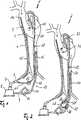
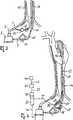
Zwei Ausführungsbeispiele erfindungsgemäßer Anordnungen sind in der Zeichnung dargestellt und werden im Folgenden näher erläutert. Es zeigtTwo embodiments of arrangements according to the invention are shown in the drawing and are explained in more detail below. It shows
Das in den Figuren gezeigte extrakorporale Life-Support-System
Im Einsatz der Anordnung kann somit über die venöse Kanüle
Bei einer pulsierenden Pumpe
Die Pumpe
Der über die Entlastungsleitung
Die in
Wie bei dem in
Die
In der
Hierfür wird eine Pumpensteuerung
Beim Betrieb des ECLS-Systems wird mit dem EKG
Bei dem in der
In allen Ausführungsbeispielen ist die venöse Kanüle
Die gezeigten Ausführungsformen entlasten das Herz insbesondere bei mangelnder Pumpleistung, bzw. Auswurfleistungsfähigkeit. Insbesondere im pulsatilen EGK-getriggerten Betrieb einer oder beider Pumpen verstärkt sich die myokardprotektive Wirkung der diastolischen Augmentation (geringere Nachlast, Erhöhung der linksventrikulären Auswurfleistung, Erniedrigung des linksventrikulären Residualvolumens) durch die Verringerung des Ventrikelvolumens erheblich. Dies führt zu einer weiteren Entlastung des linken Ventrikels und senkt die Wandspannung speziell während der Diastole, wodurch der koronare Fluss positiv beeinflusst werden kann.The embodiments shown relieve the heart in particular in the case of a lack of pumping power or ejection efficiency. In particular, in the pulsatile EGK-triggered operation of one or both pumps, the myocardial protective effect of diastolic augmentation (lower afterload, increase in left ventricular ejection, reduction of residual left ventricular volume) is significantly enhanced by the reduction in ventricular volume. This leads to a further relief of the left ventricle and reduces the wall tension, especially during diastole, whereby the coronary flow can be positively influenced.
ZITATE ENTHALTEN IN DER BESCHREIBUNG QUOTES INCLUDE IN THE DESCRIPTION
Diese Liste der vom Anmelder aufgeführten Dokumente wurde automatisiert erzeugt und ist ausschließlich zur besseren Information des Lesers aufgenommen. Die Liste ist nicht Bestandteil der deutschen Patent- bzw. Gebrauchsmusteranmeldung. Das DPMA übernimmt keinerlei Haftung für etwaige Fehler oder Auslassungen.This list of the documents listed by the applicant has been generated automatically and is included solely for the better information of the reader. The list is not part of the German patent or utility model application. The DPMA assumes no liability for any errors or omissions.
Zitierte PatentliteraturCited patent literature
- EP 2832383[0030]EP 2832383[0030]
Claims (11)
Translated fromGermanPriority Applications (7)
| Application Number | Priority Date | Filing Date | Title |
|---|---|---|---|
| DE102015000771.8ADE102015000771A1 (en) | 2015-01-26 | 2015-01-26 | Arrangement with a suction line, a pressure line and a pump |
| EP16709962.1AEP3250254B1 (en) | 2015-01-26 | 2016-01-26 | Assembly comprising a suction line, a pressure line and a pump |
| JP2017557246AJP6784913B2 (en) | 2015-01-26 | 2016-01-26 | Assembly with suction line, discharge line, and pump |
| PCT/DE2016/000025WO2016119771A2 (en) | 2015-01-26 | 2016-01-26 | Assembly comprising a suction line, a pressure line and a pump |
| CN201680016837.2ACN108601881B (en) | 2015-01-26 | 2016-01-26 | Device with suction line, pressure line and pump |
| DE112016000472.9TDE112016000472A5 (en) | 2015-01-26 | 2016-01-26 | Arrangement with a suction line, a pressure line and a pump |
| US15/660,080US10729840B2 (en) | 2015-01-26 | 2017-07-26 | Assembly comprising a suction line, a pressure line and a pump |
Applications Claiming Priority (1)
| Application Number | Priority Date | Filing Date | Title |
|---|---|---|---|
| DE102015000771.8ADE102015000771A1 (en) | 2015-01-26 | 2015-01-26 | Arrangement with a suction line, a pressure line and a pump |
Publications (1)
| Publication Number | Publication Date |
|---|---|
| DE102015000771A1true DE102015000771A1 (en) | 2016-07-28 |
Family
ID=55538151
Family Applications (2)
| Application Number | Title | Priority Date | Filing Date |
|---|---|---|---|
| DE102015000771.8AWithdrawnDE102015000771A1 (en) | 2015-01-26 | 2015-01-26 | Arrangement with a suction line, a pressure line and a pump |
| DE112016000472.9TWithdrawnDE112016000472A5 (en) | 2015-01-26 | 2016-01-26 | Arrangement with a suction line, a pressure line and a pump |
Family Applications After (1)
| Application Number | Title | Priority Date | Filing Date |
|---|---|---|---|
| DE112016000472.9TWithdrawnDE112016000472A5 (en) | 2015-01-26 | 2016-01-26 | Arrangement with a suction line, a pressure line and a pump |
Country Status (6)
| Country | Link |
|---|---|
| US (1) | US10729840B2 (en) |
| EP (1) | EP3250254B1 (en) |
| JP (1) | JP6784913B2 (en) |
| CN (1) | CN108601881B (en) |
| DE (2) | DE102015000771A1 (en) |
| WO (1) | WO2016119771A2 (en) |
Families Citing this family (7)
| Publication number | Priority date | Publication date | Assignee | Title |
|---|---|---|---|---|
| DE102017004548A1 (en)* | 2016-12-23 | 2018-06-28 | Xenios Ag | Cannula with a wire running along the cannula |
| WO2019193604A1 (en)* | 2018-04-06 | 2019-10-10 | Singru Kanha Vijay | Ventricular decompression and assisting apparatus |
| EP3662942A1 (en) | 2018-12-06 | 2020-06-10 | Xenios AG | System for cardiac assistance, method for operating the system and cardiac support method |
| WO2021037373A1 (en)* | 2019-08-30 | 2021-03-04 | Avidal Group Gmbh | Cannula for endovascular blood circuit support, corresponding assembly and method |
| US20230233746A1 (en)* | 2022-01-24 | 2023-07-27 | Cardiacassist, Inc. | Dual Lumen Drainage Cannula With Internal Flow Restrictor |
| CN118161690B (en)* | 2024-05-11 | 2024-08-13 | 中国人民解放军总医院第六医学中心 | ECMO system with dual lumen arterial cannula |
| CN118161691A (en)* | 2024-05-11 | 2024-06-11 | 中国人民解放军总医院第六医学中心 | ECMO system |
Citations (3)
| Publication number | Priority date | Publication date | Assignee | Title |
|---|---|---|---|---|
| DE8990089U1 (en)* | 1988-08-29 | 1991-08-22 | Shiley Inc., Irvine, Calif. | Peripheral cardiopulmonary bypass and coronary reperfusion system |
| DE69524217T2 (en)* | 1994-05-27 | 2002-08-22 | Heartport, Inc. | CARDIOPULMONARY BYPASS PUMP SUPPORT DURING A CARDIAC INTERVENTION |
| EP2832383A1 (en) | 2013-07-29 | 2015-02-04 | Novalung GmbH | Assembly having a blood pump and a pump control |
Family Cites Families (9)
| Publication number | Priority date | Publication date | Assignee | Title |
|---|---|---|---|---|
| US5433700A (en)* | 1992-12-03 | 1995-07-18 | Stanford Surgical Technologies, Inc. | Method for intraluminally inducing cardioplegic arrest and catheter for use therein |
| US5957879A (en)* | 1997-01-24 | 1999-09-28 | Heartport, Inc. | Methods and devices for maintaining cardiopulmonary bypass and arresting a patient's heart |
| JP4501220B2 (en) | 2000-05-12 | 2010-07-14 | 栗田工業株式会社 | Multiple disk sludge dewatering equipment |
| US20080249456A1 (en)* | 2007-03-27 | 2008-10-09 | Syuuji Inamori | Pulsation-type auxiliary circulation system, pulsatile flow generation control device, and pulsatile flow generation control method |
| JP5557175B2 (en) | 2007-03-27 | 2014-07-23 | 修二 稲盛 | Pulsating flow generation control device and pulsating flow generation control method |
| KR101729793B1 (en) | 2009-01-26 | 2017-04-24 | 쓰리엠 이노베이티브 프로퍼티즈 컴파니 | Liquid spray gun, spray gun platform, and spray head assembly |
| US20110112353A1 (en)* | 2009-11-09 | 2011-05-12 | Circulite, Inc. | Bifurcated outflow cannulae |
| US8562519B2 (en)* | 2009-12-31 | 2013-10-22 | Cardiacassist, Inc. | Pumping system and method for assisting a patient's heart |
| EP2646166B1 (en) | 2010-12-02 | 2018-11-07 | SATA GmbH & Co. KG | Spray gun and accessories |
- 2015
- 2015-01-26DEDE102015000771.8Apatent/DE102015000771A1/ennot_activeWithdrawn
- 2016
- 2016-01-26JPJP2017557246Apatent/JP6784913B2/enactiveActive
- 2016-01-26CNCN201680016837.2Apatent/CN108601881B/enactiveActive
- 2016-01-26EPEP16709962.1Apatent/EP3250254B1/enactiveActive
- 2016-01-26WOPCT/DE2016/000025patent/WO2016119771A2/ennot_activeCeased
- 2016-01-26DEDE112016000472.9Tpatent/DE112016000472A5/ennot_activeWithdrawn
- 2017
- 2017-07-26USUS15/660,080patent/US10729840B2/enactiveActive
Patent Citations (3)
| Publication number | Priority date | Publication date | Assignee | Title |
|---|---|---|---|---|
| DE8990089U1 (en)* | 1988-08-29 | 1991-08-22 | Shiley Inc., Irvine, Calif. | Peripheral cardiopulmonary bypass and coronary reperfusion system |
| DE69524217T2 (en)* | 1994-05-27 | 2002-08-22 | Heartport, Inc. | CARDIOPULMONARY BYPASS PUMP SUPPORT DURING A CARDIAC INTERVENTION |
| EP2832383A1 (en) | 2013-07-29 | 2015-02-04 | Novalung GmbH | Assembly having a blood pump and a pump control |
Also Published As
| Publication number | Publication date |
|---|---|
| JP6784913B2 (en) | 2020-11-18 |
| CN108601881B (en) | 2021-09-24 |
| JP2018502691A (en) | 2018-02-01 |
| US10729840B2 (en) | 2020-08-04 |
| WO2016119771A2 (en) | 2016-08-04 |
| US20170319774A1 (en) | 2017-11-09 |
| WO2016119771A3 (en) | 2016-10-20 |
| DE112016000472A5 (en) | 2017-10-05 |
| EP3250254A2 (en) | 2017-12-06 |
| CN108601881A (en) | 2018-09-28 |
| EP3250254B1 (en) | 2019-09-18 |
Similar Documents
| Publication | Publication Date | Title |
|---|---|---|
| DE102015000771A1 (en) | Arrangement with a suction line, a pressure line and a pump | |
| DE2707951A1 (en) | DEVICE FOR SUPPLYING A PATIENT WITH A PULSATING BLOOD FLOW | |
| DE102012207042B4 (en) | PULSATIONSBLUTPUMPE | |
| EP2523702B1 (en) | Arrangement having a blood pump and a gas exchanger for extracorporeal membrane oxygenation | |
| DE69909274T2 (en) | MECHANICAL AUXILIARY HEART FOR RESTORING HEART FUNCTION | |
| DE60310258T2 (en) | IMPLANTABLE SYSTEM FOR HEART SUPPORT | |
| EP2832383B1 (en) | Assembly having a blood pump and a pump control | |
| EP3996772B1 (en) | Control for non-occlusive blood pumps | |
| DE8990089U1 (en) | Peripheral cardiopulmonary bypass and coronary reperfusion system | |
| DE10155011A1 (en) | Intra-aortal pump system for supporting or replacing the heart pumping function is inserted into the heart and aorta using an adjustable guide and support bracket through an incision in the heart apex | |
| DE202010016802U1 (en) | catheter pump | |
| DE3728371A1 (en) | SYSTEM AND DEVICE FOR CATHETERIZING WHEN THE CHEST IS CLOSED AND FOR BYPASSING FROM THE COURTS TO A LARGE ARTERY | |
| DE69100769T2 (en) | Cardiac support device. | |
| WO2019158420A1 (en) | Pump catheter for the directed pulsatile conveying of blood | |
| EP1374928B1 (en) | Blood pump comprising an impeller | |
| WO2016008521A1 (en) | Right heart support system | |
| DE3610255A1 (en) | BLOOD RETROPERFUSION SYSTEM | |
| WO2024126626A1 (en) | Extracorporeal circuit support with cardiac activity-optimized delay time | |
| EP3452142B1 (en) | Deaerating system comprising a deaerating unit and a deaerating device set, and method for operating a deaerating system | |
| DE69302167T2 (en) | DEVICE FOR QUICK CONNECTION TO THE BLOOD CIRCUIT | |
| US20220257845A1 (en) | Dual lumen cannula system | |
| DE102023003907A1 (en) | Monitoring the effectiveness of a support pulse of extracorporeal circulatory support | |
| DD244694A1 (en) | UNIQUE BALLOON CATHETER FOR INTRA-AGAIN COUNTERPULSATION | |
| DE102011115546A1 (en) | Extracorporeal system i.e. minimized heart support system, for pumping oxygenated blood from heart through centrifugal pump, has centrifugal pump and roller pump partially connected in series with each other | |
| EP2944338A1 (en) | Autonomous cardiovascular implant with a check valve |
Legal Events
| Date | Code | Title | Description |
|---|---|---|---|
| R163 | Identified publications notified | ||
| R118 | Application deemed withdrawn due to claim for domestic priority |