DE102014226120A1 - Identification converter with cam and bearing pendulum for actuating a clutch - Google Patents
Identification converter with cam and bearing pendulum for actuating a clutchDownload PDFInfo
- Publication number
- DE102014226120A1 DE102014226120A1DE102014226120.1ADE102014226120ADE102014226120A1DE 102014226120 A1DE102014226120 A1DE 102014226120A1DE 102014226120 ADE102014226120 ADE 102014226120ADE 102014226120 A1DE102014226120 A1DE 102014226120A1
- Authority
- DE
- Germany
- Prior art keywords
- actuating
- axis
- rotation
- identifier converter
- converter
- Prior art date
- Legal status (The legal status is an assumption and is not a legal conclusion. Google has not performed a legal analysis and makes no representation as to the accuracy of the status listed.)
- Withdrawn
Links
- 238000005096rolling processMethods0.000claimsdescription25
- 230000008878couplingEffects0.000claimsdescription3
- 238000010168coupling processMethods0.000claimsdescription3
- 238000005859coupling reactionMethods0.000claimsdescription3
- 230000033001locomotionEffects0.000description7
- 238000006243chemical reactionMethods0.000description3
- 238000006073displacement reactionMethods0.000description3
- 238000009434installationMethods0.000description3
- 230000006978adaptationEffects0.000description2
- 230000003247decreasing effectEffects0.000description2
- 230000000630rising effectEffects0.000description2
- BUHVIAUBTBOHAG-FOYDDCNASA-N(2r,3r,4s,5r)-2-[6-[[2-(3,5-dimethoxyphenyl)-2-(2-methylphenyl)ethyl]amino]purin-9-yl]-5-(hydroxymethyl)oxolane-3,4-diolChemical compoundCOC1=CC(OC)=CC(C(CNC=2C=3N=CN(C=3N=CN=2)[C@H]2[C@@H]([C@H](O)[C@@H](CO)O2)O)C=2C(=CC=CC=2)C)=C1BUHVIAUBTBOHAG-FOYDDCNASA-N0.000description1
- 230000005540biological transmissionEffects0.000description1
- 210000002414legAnatomy0.000description1
- 239000007788liquidSubstances0.000description1
- 230000007246mechanismEffects0.000description1
- 210000000689upper legAnatomy0.000description1
Images


Classifications
- F—MECHANICAL ENGINEERING; LIGHTING; HEATING; WEAPONS; BLASTING
- F16—ENGINEERING ELEMENTS AND UNITS; GENERAL MEASURES FOR PRODUCING AND MAINTAINING EFFECTIVE FUNCTIONING OF MACHINES OR INSTALLATIONS; THERMAL INSULATION IN GENERAL
- F16D—COUPLINGS FOR TRANSMITTING ROTATION; CLUTCHES; BRAKES
- F16D28/00—Electrically-actuated clutches
- F—MECHANICAL ENGINEERING; LIGHTING; HEATING; WEAPONS; BLASTING
- F16—ENGINEERING ELEMENTS AND UNITS; GENERAL MEASURES FOR PRODUCING AND MAINTAINING EFFECTIVE FUNCTIONING OF MACHINES OR INSTALLATIONS; THERMAL INSULATION IN GENERAL
- F16D—COUPLINGS FOR TRANSMITTING ROTATION; CLUTCHES; BRAKES
- F16D23/00—Details of mechanically-actuated clutches not specific for one distinct type
- F16D23/12—Mechanical clutch-actuating mechanisms arranged outside the clutch as such
- F16D2023/123—Clutch actuation by cams, ramps or ball-screw mechanisms
- F—MECHANICAL ENGINEERING; LIGHTING; HEATING; WEAPONS; BLASTING
- F16—ENGINEERING ELEMENTS AND UNITS; GENERAL MEASURES FOR PRODUCING AND MAINTAINING EFFECTIVE FUNCTIONING OF MACHINES OR INSTALLATIONS; THERMAL INSULATION IN GENERAL
- F16D—COUPLINGS FOR TRANSMITTING ROTATION; CLUTCHES; BRAKES
- F16D25/00—Fluid-actuated clutches
- F16D25/12—Details not specific to one of the before-mentioned types
Landscapes
- Engineering & Computer Science (AREA)
- General Engineering & Computer Science (AREA)
- Mechanical Engineering (AREA)
- Physics & Mathematics (AREA)
- Electromagnetism (AREA)
- Transmission Devices (AREA)
Abstract
Translated fromGerman
Description
Translated fromGermanStand der TechnikState of the art
Die vorliegende Erfindung betrifft einen Kennungswandler zum Betätigen eines Zylinders, insbesondere einer Kupplung eines Kraftfahrzeugs, mit einer Betätigungsscheibe, die um eine Drehachse in und gegen eine Drehrichtung drehbar ist, und einem Stößel, der in und gegen eine Schieberichtung verschiebbar ist, wobei die Betätigungsscheibe zum Verschieben des Stößels vorgesehen ist, wobei zwischen der Betätigungsscheibe und dem Stößel ein Betätigungselement angeordnet ist. Die vorliegende Erfindung betrifft zudem eine Betätigungsanordnung mit einem solchen Kennungswandler und einem Verstellantrieb zum automatischen Antreiben des Kennungswandlers, sowie eine Kupplung, insbesondere eines Kraftfahrzeugs, mit einem solchen Kennungswandler.The present invention relates to a characteristic converter for actuating a cylinder, in particular a clutch of a motor vehicle, with an actuating disk, which is rotatable about an axis of rotation in and against a rotational direction, and a plunger, which is displaceable in and against a sliding direction, wherein the actuating disk for Moving the plunger is provided, wherein between the actuating disk and the plunger, an actuating element is arranged. The present invention also relates to an actuating arrangement with such a tag converter and an adjusting drive for the automatic driving of the identification converter, as well as a clutch, in particular of a motor vehicle, with such a tag converter.
Trockenkupplungen in einem Kraftfahrzeug werden von einem Kraftfahrzeugfahrer über einen hydraulischen Geberzylinder und einen hydraulischen Nehmerzylinder, oder mit Seilzügen betätigt. Es sind auch Trockenkupplungen bekannt, bei denen die Betätigung automatisiert erfolgt. Bei automatisierten Trockenkupplungen wird der Geberzylinder des Systems mittels eines Getriebes von einem Elektromotor betätigt. Solche Getriebe umfassen zumeist einen Kennungswandler, der eine erste Stufe mit einem Schraubrad- oder Stirnradgetriebe aufweist, sowie eine zweite Stufe, die die Drehbewegung der ersten Stufe in eine lineare Bewegung, beispielsweise eines Stößels, wandelt. Dafür umfasst die zweite Stufe häufig Kurbeltriebe oder Spindeltriebe. Es sind aber auch Nockenscheiben verwendbar.Dry clutches in a motor vehicle are actuated by a motor vehicle driver via a hydraulic master cylinder and a hydraulic slave cylinder, or with cables. Dry clutches are also known in which the actuation is automated. In automated dry clutches, the master cylinder of the system is actuated by a gear by an electric motor. Such transmissions typically include a tag converter having a first stage with a helical or spur gear, and a second stage that converts the first stage rotational movement into a linear motion, such as a plunger. For the second stage often includes crank mechanisms or spindle drives. But there are also cams usable.
Die Druckschrift
Bei Verwendung von Nockenscheiben werden auf den Stößel jedoch entsprechend der Steigung des Nockens nicht nur Nutzkräfte in Richtung des Stößels, sondern zudem Querkräfte ausgeübt.When using cams but not only useful forces in the direction of the plunger, but also transverse forces are exerted on the plunger, however, according to the slope of the cam.
Offenbarung der ErfindungDisclosure of the invention
Aufgabe der vorliegenden Erfindung ist es, einen Kennungswandler zur Betätigung eines Zylinders, insbesondere einer Kupplung eines Kraftfahrzeugs, zu schaffen, der eine rotatorische Bewegung verlustarm in eine lineare Bewegung wandelt. Eine weitere Aufgabe der Erfindung ist es, eine Kupplung eines Kraftfahrzeugs zu schaffen, die einen solchen verlustarm betreibbaren Kennungswandler umfasst, sehr flexibel an die Bauraumverhältnisse im Kraftfahrzeug anpassbar ist und wenig Bauraum einnimmt.Object of the present invention is to provide a characteristic converter for actuating a cylinder, in particular a clutch of a motor vehicle, which converts a rotational movement with low loss in a linear movement. A further object of the invention is to provide a clutch of a motor vehicle which comprises such a low-loss operable identifier converter, is very flexible adaptable to the space conditions in the motor vehicle and takes up little space.
Die Aufgabe wird gelöst mit einem Kennungswandler zum Betätigen eines Zylinders. Der Zylinder ist bevorzugt ein Hydraulikzylinder. Die Erfindung eignet sich aber auch zur Betätigung eines Pneumatikzylinders, zum Betätigen einer Pumpe oder ähnlich. In einer bevorzugten Ausführungsform ist der Zylinder ein Geberzylinder einer Kupplung, insbesondere einer Trockenkupplung, eines Kraftfahrzeugs.The object is achieved with an identifier converter for actuating a cylinder. The cylinder is preferably a hydraulic cylinder. However, the invention is also suitable for actuating a pneumatic cylinder, for actuating a pump or the like. In a preferred embodiment, the cylinder is a master cylinder of a clutch, in particular a dry clutch, of a motor vehicle.
Der Kennungswandler weist eine Betätigungsscheibe auf, die um eine Drehachse in und gegen eine Drehrichtung drehbar ist. Zudem weist der Kennungswandler einen Stößel auf, der in einer Schieberichtung angeordnet, und in und gegen die Schieberichtung verschiebbar ist. Die Betätigungsscheibe ist zum Verschieben des Stößels vorgesehen. Der Stößel ist zum Betätigen des Zylinders vorgesehen. Im Folgenden werden die Begriffe Betätigen des Kennungswandlers und Drehen der Betätigungsscheibe synonym verwendet.The identification converter has an actuating disk, which is rotatable about an axis of rotation in and against a direction of rotation. In addition, the identifier converter on a plunger, which is arranged in a sliding direction, and is displaceable in and against the sliding direction. The actuating disk is provided for displacing the plunger. The plunger is provided for actuating the cylinder. In the following, the terms operating the identification converter and rotating the actuating disk are used synonymously.
Zwischen der Betätigungsscheibe und dem Stößel ist ein Betätigungselement angeordnet.Between the actuating disc and the plunger, an actuating element is arranged.
Der Kennungswandler zeichnet sich dadurch aus, dass das Betätigungselement um eine Schwenkachse in und gegen eine Schwenkrichtung schwenkbar gelagert ist.The identifier converter is characterized in that the actuating element is mounted pivotably about a pivot axis in and against a pivoting direction.
Da das Betätigungselement zwischen der Betätigungsscheibe und dem Stößel angeordnet ist, wirken die Kräfte, insbesondere die Querkräfte, die beim Drehen der Betätigungsscheibe auftreten, zunächst auf das Betätigungselement. Dadurch wird das Betätigungselement beim Betätigen des Kennungswandlers um seine Schwenkachse gedreht. Dabei werden auf das Betätigungselement wirkende Querkräfte in einem Schwenklager, in oder an dem das Betätigungselement schwenkbar gelagert ist, abgestützt.Since the actuating element is arranged between the actuating disk and the plunger, the forces, in particular the transverse forces which occur when the actuating disk is rotated, first act on the actuating element. As a result, the actuating element is rotated about its pivot axis when the identification converter is actuated. In this case acting on the actuating element transverse forces in a pivot bearing, in or on which the actuating element is pivotally mounted, supported.
Es ist bevorzugt, dass das Betätigungselement, insbesondere beim Betätigen des Kennungswandlers, in einem ersten Anlagebereich, insbesondere in einem ersten punkt- oder linienförmigen Anlagebereich, an der Betätigungsscheibe anliegt. Da sich die Betätigungsscheibe beim Betätigen des Kennungswandlers um ihre Drehachse dreht, verschiebt sich der erste Anlagebereich entlang einer Betätigungsfläche der Betätigungsscheibe. Um ein verlustarmes Betätigen des Kennungswandlers zu ermöglichen, ist es bevorzugt, dass das Betätigungselement ein erstes Abrollmittel aufweist, welches um eine erste Abrollachse in und gegen eine erste Abrollrichtung drehbar gelagert ist. Bevorzugt rollt sich das erste Abrollmittel beim Betätigen des Kennungswandlers an der Betätigungsfläche der Betätigungsscheibe ab. Bevorzugt ist der erste Anlagebereich daher am ersten Abrollmittel angeordnet.It is preferred that the actuating element, in particular during actuation of the identifier converter, bears against the actuating disk in a first contact area, in particular in a first point-like or linear contact area. Since the actuating disk rotates about its axis of rotation when the identifier converter is actuated, the first abutment region shifts along an actuating surface of the actuating disk. In order to enable a low-loss actuation of the identifier converter, it is preferred that the actuating element a first unrolling means, which is rotatably mounted about a first rolling axis in and against a first rolling direction. The first unrolling means preferably rolls off on actuation of the identifier converter on the actuating surface of the actuating disk. The first contact area is therefore preferably arranged on the first unrolling means.
Weiterhin bevorzugt liegt das Betätigungselement, insbesondere beim Betätigen des Kennungswandlers, in einem zweiten Anlagebereich, insbesondere in einem zweiten punkt- oder linienförmigen Anlagebereich, an dem Stößel an. Da das Betätigungselement beim Drehen der Betätigungsscheibe um seine Schwenkachse verschwenkt wird, verschiebt sich der zweite Anlagebereich entlang einer Stößelfläche des Stößels. Um ein verlustarmes Betätigen des Kennungswandlers zu ermöglichen, ist es bevorzugt, dass das Betätigungselement ein zweites Abrollmittel aufweist, welches um eine zweite Abrollachse in und gegen eine zweite Abrollrichtung drehbar gelagert ist. Bevorzugt rollt sich das zweite Abrollmittel beim Betätigen des Kennungswandlers an der Stößelfläche des Stößels ab. Bevorzugt ist der zweite Anlagebereich daher am zweiten Abrollmittel angeordnet.Further preferably, the actuating element, in particular when operating the identifier converter, in a second contact area, in particular in a second point or linear contact area, on the plunger. Since the actuating element is pivoted about its pivot axis when the actuating disk is rotated, the second bearing region shifts along a plunger surface of the plunger. In order to enable low-loss actuation of the identifier converter, it is preferred that the actuating element has a second unrolling means which is rotatably mounted about a second unwinding axis in and against a second unwinding direction. Preferably, the second unrolling rolls on actuation of the identification converter on the plunger surface of the plunger. The second contact area is therefore preferably arranged on the second unrolling means.
Da sich das erste und das zweite Abrollmittel beim Betätigen der Betätigungsscheibe jeweils an einer Fläche abrollen, treten nur geringe Reibungsverluste auf. Dabei ist es bevorzugt, dass das erste und das zweite Abrollmittel voneinander beabstandet sind, so dass sie sich beim Abrollen nicht behindern. Vorzugsweise sind die Anlagebereiche in Drehrichtung und/oder in axialer Richtung der Drehachse voneinander beabstandet. Dadurch ist eine sehr flexible Anpassung des Kennungswandlers an die Einbauverhältnisse möglich.Since the first and the second unwinding roll on actuation of the actuating disk in each case on a surface, only small friction losses occur. It is preferred that the first and the second unrolling means are spaced apart so that they do not interfere with the unrolling. Preferably, the abutment areas are spaced apart in the direction of rotation and / or in the axial direction of the axis of rotation. This allows a very flexible adaptation of the identifier converter to the installation conditions.
Das erste und das zweite Abrollmittel sind bevorzugt in Schwenkrichtung der Schwenkachse voneinander beabstandet. Vorzugsweise erstrecken sich die erste und die zweite Abrollachse parallel der Schwenkachse. Weiterhin bevorzugt sind die erste und die zweite Abrollfläche parallel zueinander angeordnet. Ebenfalls bevorzugt erstrecken sich die Abrollflächen in Richtung der Schwenkachse.The first and the second unrolling means are preferably spaced apart in the pivoting direction of the pivot axis. Preferably, the first and the second rolling axis extend parallel to the pivot axis. Further preferably, the first and the second rolling surface are arranged parallel to each other. Also preferably, the rolling surfaces extend in the direction of the pivot axis.
In einer bevorzugten Ausführungsform ist die Schieberichtung eine radiale Richtung der Drehachse. Es ist aber besonders bevorzugt, dass die Schieberichtung einen Verstellwinkel zur radialen Richtung der Drehachse aufweist. Dadurch ist der Kennungswandler kompakter baubar.In a preferred embodiment, the sliding direction is a radial direction of the axis of rotation. However, it is particularly preferred that the sliding direction has an adjustment angle to the radial direction of the axis of rotation. As a result, the identifier converter is compact buildable.
Weiterhin bevorzugt sind die Schwenkachse und/oder die Abrollachsen quer zur Schieberichtung angeordnet. Sie erstrecken sich daher bevorzugt parallel der Drehachse. Bei dieser Anordnung werden Kräfte, die von der Betätigungsscheibe aus in die Schieberichtung auf das Betätigungselement wirken, vom ersten Abrollmittel aus über das zweite Abrollmittel auf den Stößel übertragen.Further preferably, the pivot axis and / or the rolling axes are arranged transversely to the sliding direction. They therefore preferably extend parallel to the axis of rotation. In this arrangement, forces acting from the actuating disk in the sliding direction on the actuating element, transmitted from the first rolling means on the second rolling-off means on the plunger.
Besonders bevorzugt weisen die erste und die zweite Abrollachse denselben Abstand zur Schwenkachse auf. Sie sind bevorzugt jeweils in einer radialen Richtung der Schwenkachse von dieser beabstandet. Ganz besonders bevorzugt sind sie auf einer Kreisbahn um die Schwenkachse angeordnet. In dieser Ausführungsform sind die Abrollachsen und die Schwenkachse in einem gleichschenkligen Dreieck angeordnet. Das Betätigungselement weist dann in einer ersten bevorzugten Ausführungsform etwa die Form eines Dreiecks oder eines Kreissektors auf.Particularly preferably, the first and the second roll-off axis at the same distance from the pivot axis. They are preferably each spaced in a radial direction of the pivot axis of this. Most preferably, they are arranged on a circular path about the pivot axis. In this embodiment, the rolling axes and the pivot axis are arranged in an isosceles triangle. The actuating element then has, in a first preferred embodiment, approximately the shape of a triangle or a circular sector.
In dieser Ausführungsform umfasst das Betätigungselement einen Gelenkarm, mit einem ersten Ende, an dem ein Schwenkkopf um die Schwenkachse schwenkbar gelagert ist, und mit einem zweiten Ende, an dem die Abrollmittel angeordnet sind. Diese Ausführungsform des Kennungswandlers ist sehr flach baubar.In this embodiment, the actuating element comprises an articulated arm, with a first end, on which a pivoting head is pivotally mounted about the pivot axis, and with a second end, on which the unrolling means are arranged. This embodiment of the identifier converter is very flat buildable.
In einer zweiten bevorzugten Ausführungsform umfasst das Betätigungselement einen ersten Gelenkarm sowie einen zweiten Gelenkarm. Die Gelenkarme weisen jeweils das erste Ende sowie das zweite Ende auf. Am ersten Ende der Gelenkarme ist bevorzugt jeweils ein Schwenkkopf um die Schwenkachse schwenkbar angeordnet. Weiterhin bevorzugt ist am zweiten Ende der Gelenkarme jeweils eines der Abrollmittel angeordnet. Es ist bevorzugt, dass die Gelenkarme in axialer Richtung der Schwenkachse voneinander beabstandet angeordnet sind. Diese Ausführungsform ermöglicht eine sehr flexible Anpassung des Kennungswandlers an die Bauraumverhältnisse.In a second preferred embodiment, the actuating element comprises a first articulated arm and a second articulated arm. The articulated arms each have the first end and the second end. At the first end of the articulated arms, a pivoting head is preferably arranged pivotably about the pivot axis. Further preferably, one of the unrolling means is arranged at the second end of the articulated arms. It is preferred that the articulated arms are arranged spaced apart in the axial direction of the pivot axis. This embodiment allows a very flexible adaptation of the identifier converter to the installation space conditions.
Vorzugsweise weisen die Gelenkarme dieselbe Länge auf. Dadurch sind die Abrollachsen und die Schwenkachse auch bei dieser Ausführungsform des Kennungswandlers in einem gleichschenkligen Dreieck angeordnet.Preferably, the articulated arms have the same length. As a result, the roll-off axes and the pivot axis are also arranged in an isosceles triangle in this embodiment of the identification transformer.
Die Schwenkköpfe der Gelenkarme sind bevorzugt drehfest an einer Schwenkwelle angeordnet, die sich konzentrisch um die Schwenkachse erstreckt und um die Schwenkachse drehbar in zumindest einem, vorzugsweise in zwei, Schwenklagern gelagert ist. Eine solche Lagerung ist mit herkömmlichen Lagern, insbesondere Rolllagern, kostengünstig möglich. Dabei sind Lager wählbar, die ein verlustarmes Schwenken der Gelenkarme ermöglichen und eine lange Lebensdauer aufweisen.The swivel heads of the articulated arms are preferably arranged non-rotatably on a pivot shaft, which extends concentrically around the pivot axis and is rotatably mounted about the pivot axis in at least one, preferably in two, pivot bearings. Such storage is possible inexpensively with conventional bearings, especially roller bearings. Here, bearings are available that allow low-loss pivoting of the articulated arms and have a long life.
Die Betätigungsscheibe ist bevorzugt eine Nockenscheibe. Vorzugsweise weist sie einen Betätigungsbereich und einen Betätigungsanschlag auf. Die Betätigungsfläche ist bevorzugt im Betätigungsbereich angeordnet. Es ist besonders bevorzugt, dass sich ein Achsabstand der Betätigungsfläche von der Drehachse im Betätigungsbereich stetig vergrößert. Dadurch wird der Stößel beim Betätigen der Betätigungsscheibe kontinuierlich verschoben.The actuating disk is preferably a cam disk. Preferably, it has an actuation area and an actuation stop. The actuating surface is preferably in Operating area arranged. It is particularly preferred that an axial distance of the actuating surface from the axis of rotation in the operating area increases steadily. As a result, the plunger is moved continuously during actuation of the actuating disk.
Bevorzugt ist die Vergrößerung des Achsabstandes zumindest teilweise oder überall gleich. In dieser Ausführungsform wird der Stößel mit gleichbleibender Geschwindigkeit verschoben. Weiterhin ist eine Ausführungsform bevorzugt, in der sich die Vergrößerung des Achsabstandes zumindest teilweise ändert, insbesondere stetig vergrößert oder verkleinert. Bei steigender Vergrößerung des Achsabstandes wird der Stößel beim Verschieben beschleunigt, bei sinkender Vergrößerung wird er gebremst.Preferably, the increase in the axial distance is at least partially or everywhere the same. In this embodiment, the plunger is moved at a constant speed. Furthermore, an embodiment is preferred in which the increase in the axial distance changes at least partially, in particular continuously increased or decreased. With increasing enlargement of the axial distance of the plunger is accelerated when moving, with decreasing magnification, it is braked.
Es ist ebenfalls bevorzugt, dass der Achsabstand zumindest teilweise unverändert ist. Bei unverändertem Achsabstand wird der Stößel nicht verschoben. Daher ist die Bewegung des Stößels durch den Achsabstand der Betätigungsfläche von der Drehachse, der eine Querschnittskontur der Betätigungsscheibe bestimmt, einstellbar.It is also preferred that the axial distance is at least partially unchanged. With unchanged center distance, the plunger is not moved. Therefore, the movement of the plunger is adjustable by the axial distance of the actuating surface of the rotation axis, which determines a cross-sectional contour of the actuating disc.
Die Aufgabe wird weiterhin gelöst mit einer Betätigungsanordnung für einen Zylinder, beispielsweise für einen Geberzylinder einer Kupplung eines Kraftfahrzeugs. Die Betätigungsanordnung weist einen solchen Kennungswandler auf, sowie einen Verstellantrieb zum automatischen Antreiben des Kennungswandlers. Es ist bevorzugt, dass eine Abtriebsachse des Verstellantriebs quer zur Drehachse angeordnet ist. Dadurch ist die Betätigungsanordnung sehr flach / kompakt baubar. In Abhängigkeit von den Bauraumverhältnissen sind aber auch andere Anordnungen bevorzugt. Besonders bevorzugt weist die Abtriebsachse einen Winkel zur radialen Richtung der Drehachse auf. Dadurch ist die Lage des Verstellantriebs relativ zum Kennungswandler anpassbar.The object is further achieved with an actuating arrangement for a cylinder, for example for a master cylinder of a clutch of a motor vehicle. The actuating arrangement has such a characteristic converter, as well as an adjusting drive for automatically driving the identifier converter. It is preferred that an output axis of the adjustment drive is arranged transversely to the axis of rotation. As a result, the actuator assembly is very flat / compact buildable. Depending on the space requirements but other arrangements are preferred. Particularly preferably, the output axis has an angle to the radial direction of the axis of rotation. As a result, the position of the adjusting drive can be adapted relative to the identifier converter.
Die Aufgabe wird weiterhin gelöst mit einer Kupplung, insbesondere eines Kraftfahrzeugs, mit einem solchen Kennungswandler.The object is further achieved with a clutch, in particular a motor vehicle, with such a tag converter.
Da nahezu keine oder gar keine Querkräfte am Stößel auftreten, ist die Lagerung des Stößels kostengünstig herstellbar. Zudem ermöglicht das Betätigungselement, insbesondere aufgrund der Abrollmittel, ein verlustarmes Verschieben des Stößels. Daher weist die Kupplung, insbesondere der Stößel, sowie die Lagerung des Stößels und des Betätigungselementes, eine sehr gute Lebensdauer auf. Die Kupplung ist daher sehr kosteneffizient herstellbar.Since almost no or no transverse forces on the plunger, the storage of the plunger is inexpensive to produce. In addition, the actuating element, in particular due to the unrolling means, enables a low-loss displacement of the plunger. Therefore, the coupling, in particular the plunger, and the storage of the plunger and the actuating element, a very good life. The coupling is therefore very cost-effectively.
Im Folgenden wird die Erfindung anhand von Figuren beschrieben. Die Figuren sind lediglich beispielhaft und schränken den allgemeinen Erfindungsgedanken nicht ein.In the following the invention will be described with reference to figures. The figures are merely exemplary and do not limit the general idea of the invention.
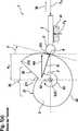
Die
Weiterhin umfasst der Kennungswandler
Zwischen dem Stößel
Das Betätigungselement
Das Abrollmittel
Bei der Betätigungsanordnung
Das Antriebsrad
Da die Querschnittskontur
Die Querkraft RR muss im ersten Lager
Es hat sich gezeigt, dass die von dem ersten Lager
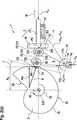
Die
Der Kennungswandler
Zwischen der Betätigungsscheibe
Das Betätigungselement
Am zweiten Ende E2 ist ein erstes Abrollmittel
Die erste Abrollachse
Das erste Abrollmittel
Beim Betätigen des Kennungswandlers
Bei steigendem Achsabstand A2 der Betätigungsfläche
Aufgrund der Reaktionskraft R wird das Betätigungselement
Da das zweite Abrollmittel
Bei dieser Ausführungsform des Kennungswandlers
Analog der Betätigungsanordnung
Außerdem erstreckt sich die Schieberichtung
Die Betätigungsscheibe
Dabei wird der Stößel
Der Stößel
Die Betätigungsanordnung
Die Abrollachsen
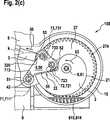
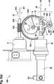
In den
Der Kennungswandler
Das Betätigungselement
Am zweiten Ende E2 ist jeweils eines der beiden Abrollmittel
Zudem sind die Abrollmittel
In axialer Richtung
Die Betätigungsanordnung
ZITATE ENTHALTEN IN DER BESCHREIBUNG QUOTES INCLUDE IN THE DESCRIPTION
Diese Liste der vom Anmelder aufgeführten Dokumente wurde automatisiert erzeugt und ist ausschließlich zur besseren Information des Lesers aufgenommen. Die Liste ist nicht Bestandteil der deutschen Patent- bzw. Gebrauchsmusteranmeldung. Das DPMA übernimmt keinerlei Haftung für etwaige Fehler oder Auslassungen.This list of the documents listed by the applicant has been generated automatically and is included solely for the better information of the reader. The list is not part of the German patent or utility model application. The DPMA assumes no liability for any errors or omissions.
Zitierte PatentliteraturCited patent literature
- DE 602004011168 T2[0003]DE 602004011168 T2[0003]
Claims (15)
Translated fromGermanPriority Applications (3)
| Application Number | Priority Date | Filing Date | Title |
|---|---|---|---|
| DE102014226120.1ADE102014226120A1 (en) | 2014-12-16 | 2014-12-16 | Identification converter with cam and bearing pendulum for actuating a clutch |
| PCT/EP2015/074074WO2016096189A1 (en) | 2014-12-16 | 2015-10-19 | Torque and speed converter having a cam disk and a bearing-mounted swinging link for actuating a clutch |
| EP15781644.8AEP3234397A1 (en) | 2014-12-16 | 2015-10-19 | Torque and speed converter having a cam disk and a bearing-mounted swinging link for actuating a clutch |
Applications Claiming Priority (1)
| Application Number | Priority Date | Filing Date | Title |
|---|---|---|---|
| DE102014226120.1ADE102014226120A1 (en) | 2014-12-16 | 2014-12-16 | Identification converter with cam and bearing pendulum for actuating a clutch |
Publications (1)
| Publication Number | Publication Date |
|---|---|
| DE102014226120A1true DE102014226120A1 (en) | 2016-06-16 |
Family
ID=54330762
Family Applications (1)
| Application Number | Title | Priority Date | Filing Date |
|---|---|---|---|
| DE102014226120.1AWithdrawnDE102014226120A1 (en) | 2014-12-16 | 2014-12-16 | Identification converter with cam and bearing pendulum for actuating a clutch |
Country Status (3)
| Country | Link |
|---|---|
| EP (1) | EP3234397A1 (en) |
| DE (1) | DE102014226120A1 (en) |
| WO (1) | WO2016096189A1 (en) |
Cited By (8)
| Publication number | Priority date | Publication date | Assignee | Title |
|---|---|---|---|---|
| DE102016209427B3 (en)* | 2016-05-31 | 2017-07-06 | Robert Bosch Gmbh | clutch |
| DE102016209431B3 (en)* | 2016-05-31 | 2017-08-03 | Robert Bosch Gmbh | clutch |
| DE102016207237A1 (en)* | 2016-04-28 | 2017-11-02 | Robert Bosch Gmbh | Actuator for actuating a clutch of a vehicle |
| DE102016220720B3 (en)* | 2016-10-21 | 2017-11-30 | Robert Bosch Gmbh | Transmission device of an electric clutch actuator |
| DE102016220732B3 (en)* | 2016-10-21 | 2018-03-01 | Robert Bosch Gmbh | Power transmission device of an electric clutch actuator |
| DE102016219059A1 (en)* | 2016-09-30 | 2018-04-05 | Schaeffler Technologies AG & Co. KG | Actuator for a clutch and roller bearings, in particular for the actuator |
| DE102016222836A1 (en) | 2016-11-21 | 2018-05-24 | Robert Bosch Gmbh | Device for actuating a clutch of a vehicle |
| DE102017208732A1 (en) | 2017-05-23 | 2018-11-29 | Robert Bosch Gmbh | Method for checking an electric clutch actuator and electric clutch actuator |
Citations (1)
| Publication number | Priority date | Publication date | Assignee | Title |
|---|---|---|---|---|
| DE602004011168T2 (en) | 2003-10-31 | 2008-12-24 | Sila Holding Industriale S.P.A., Nichelino | Electromechanical actuator for a clutch of a motor vehicle |
Family Cites Families (4)
| Publication number | Priority date | Publication date | Assignee | Title |
|---|---|---|---|---|
| DE19723394B4 (en)* | 1996-06-05 | 2013-08-14 | Schaeffler Technologies AG & Co. KG | actuator |
| DE10235906A1 (en)* | 2002-08-06 | 2004-02-19 | Zf Sachs Ag | Torque transmission device in a motor vehicle |
| US7150348B2 (en)* | 2003-10-07 | 2006-12-19 | Magneti Marelli Powertrain Usa Llc | Ergonomic clutch actuator |
| JP5461314B2 (en)* | 2010-06-08 | 2014-04-02 | 本田技研工業株式会社 | Clutch device |
- 2014
- 2014-12-16DEDE102014226120.1Apatent/DE102014226120A1/ennot_activeWithdrawn
- 2015
- 2015-10-19EPEP15781644.8Apatent/EP3234397A1/ennot_activeWithdrawn
- 2015-10-19WOPCT/EP2015/074074patent/WO2016096189A1/enactiveApplication Filing
Patent Citations (1)
| Publication number | Priority date | Publication date | Assignee | Title |
|---|---|---|---|---|
| DE602004011168T2 (en) | 2003-10-31 | 2008-12-24 | Sila Holding Industriale S.P.A., Nichelino | Electromechanical actuator for a clutch of a motor vehicle |
Cited By (10)
| Publication number | Priority date | Publication date | Assignee | Title |
|---|---|---|---|---|
| DE102016207237A1 (en)* | 2016-04-28 | 2017-11-02 | Robert Bosch Gmbh | Actuator for actuating a clutch of a vehicle |
| DE102016207237B4 (en)* | 2016-04-28 | 2018-02-22 | Robert Bosch Gmbh | Actuator for actuating a clutch of a vehicle |
| DE102016209427B3 (en)* | 2016-05-31 | 2017-07-06 | Robert Bosch Gmbh | clutch |
| DE102016209431B3 (en)* | 2016-05-31 | 2017-08-03 | Robert Bosch Gmbh | clutch |
| CN107435694A (en)* | 2016-05-31 | 2017-12-05 | 罗伯特·博世有限公司 | Clutch actuator |
| DE102016219059A1 (en)* | 2016-09-30 | 2018-04-05 | Schaeffler Technologies AG & Co. KG | Actuator for a clutch and roller bearings, in particular for the actuator |
| DE102016220720B3 (en)* | 2016-10-21 | 2017-11-30 | Robert Bosch Gmbh | Transmission device of an electric clutch actuator |
| DE102016220732B3 (en)* | 2016-10-21 | 2018-03-01 | Robert Bosch Gmbh | Power transmission device of an electric clutch actuator |
| DE102016222836A1 (en) | 2016-11-21 | 2018-05-24 | Robert Bosch Gmbh | Device for actuating a clutch of a vehicle |
| DE102017208732A1 (en) | 2017-05-23 | 2018-11-29 | Robert Bosch Gmbh | Method for checking an electric clutch actuator and electric clutch actuator |
Also Published As
| Publication number | Publication date |
|---|---|
| WO2016096189A1 (en) | 2016-06-23 |
| EP3234397A1 (en) | 2017-10-25 |
Similar Documents
| Publication | Publication Date | Title |
|---|---|---|
| DE102014226120A1 (en) | Identification converter with cam and bearing pendulum for actuating a clutch | |
| DE102008059989B4 (en) | clutch drive | |
| DE102017102804A1 (en) | Device and method for actuating a parking brake | |
| WO2012136315A1 (en) | Electromechanical power steering system with play compensation for the worm gear mechanism | |
| EP1455106A1 (en) | Disengaging system | |
| DE102015110186A1 (en) | Actuator for a clutch, in particular a motor vehicle | |
| EP1537340B1 (en) | Disk brake | |
| EP3346155B1 (en) | Brake with brake cylinder and integrated wear adjuster | |
| EP2990681B1 (en) | Actuation unit for a clutch and motor vehicle | |
| EP1724484B1 (en) | Device for actuating a coupling | |
| DE102007003338A1 (en) | Actuating device for force compensation, in particular for a motor vehicle clutch | |
| EP2427669B1 (en) | Parking brake device of a railway vehicle having high efficiency | |
| WO2016188732A1 (en) | Torque and speed converter having a cam disc and a tappet, positioned to minimise transverse force, for actuating a clutch | |
| EP1659017B1 (en) | Apparatus for reduction of the pedal force | |
| DE102017124131A1 (en) | Actuator with two spherical segments of different diameter and switching unit | |
| EP3980658B1 (en) | Brake device | |
| DE10234371B4 (en) | Lockable locking device | |
| DE102019113857B4 (en) | TRANSMISSION CLUTCH ARRANGEMENT | |
| WO2008017640A2 (en) | Adjustment device for clutches or gear locks, in particular of motor vehicles | |
| DE202011002132U1 (en) | Getriebeexzenter | |
| EP3091246B1 (en) | Disc brake | |
| DE102014210456A1 (en) | Drum brake with two brake shoes | |
| DE102023128950B4 (en) | Friction clutch | |
| DE102005050760A1 (en) | Pedal force reduction device for motor vehicle, has piston rod indirectly connected to pedal in form-fitting manner | |
| WO2024208393A1 (en) | Friction clutch |
Legal Events
| Date | Code | Title | Description |
|---|---|---|---|
| R119 | Application deemed withdrawn, or ip right lapsed, due to non-payment of renewal fee |