DE102014217275A1 - Rotor for a gantry of a computed tomography device - Google Patents
Rotor for a gantry of a computed tomography deviceDownload PDFInfo
- Publication number
- DE102014217275A1 DE102014217275A1DE102014217275.6ADE102014217275ADE102014217275A1DE 102014217275 A1DE102014217275 A1DE 102014217275A1DE 102014217275 ADE102014217275 ADE 102014217275ADE 102014217275 A1DE102014217275 A1DE 102014217275A1
- Authority
- DE
- Germany
- Prior art keywords
- rotor
- section
- hollow body
- planar part
- axis
- Prior art date
- Legal status (The legal status is an assumption and is not a legal conclusion. Google has not performed a legal analysis and makes no representation as to the accuracy of the status listed.)
- Withdrawn
Links
- 238000002591computed tomographyMethods0.000titleclaimsabstractdescription27
- 239000002826coolantSubstances0.000claimsdescription8
- 229910052751metalInorganic materials0.000claimsdescription5
- 239000002184metalSubstances0.000claimsdescription5
- 239000000463materialSubstances0.000description21
- 229910000831SteelInorganic materials0.000description10
- 239000010959steelSubstances0.000description10
- 238000001816coolingMethods0.000description9
- 238000005452bendingMethods0.000description6
- 239000011343solid materialSubstances0.000description4
- 229910000838Al alloyInorganic materials0.000description3
- 229910052782aluminiumInorganic materials0.000description3
- XAGFODPZIPBFFR-UHFFFAOYSA-NaluminiumChemical compound[Al]XAGFODPZIPBFFR-UHFFFAOYSA-N0.000description3
- 238000005266castingMethods0.000description2
- 238000013016dampingMethods0.000description2
- 238000005096rolling processMethods0.000description2
- 238000007493shaping processMethods0.000description2
- 239000007787solidSubstances0.000description2
- BUHVIAUBTBOHAG-FOYDDCNASA-N(2r,3r,4s,5r)-2-[6-[[2-(3,5-dimethoxyphenyl)-2-(2-methylphenyl)ethyl]amino]purin-9-yl]-5-(hydroxymethyl)oxolane-3,4-diolChemical compoundCOC1=CC(OC)=CC(C(CNC=2C=3N=CN(C=3N=CN=2)[C@H]2[C@@H]([C@H](O)[C@@H](CO)O2)O)C=2C(=CC=CC=2)C)=C1BUHVIAUBTBOHAG-FOYDDCNASA-N0.000description1
- 239000011324beadSubstances0.000description1
- 239000002131composite materialSubstances0.000description1
- 238000010276constructionMethods0.000description1
- 230000006735deficitEffects0.000description1
- 230000001419dependent effectEffects0.000description1
- 238000006073displacement reactionMethods0.000description1
- 239000000835fiberSubstances0.000description1
- 239000000945fillerSubstances0.000description1
- 238000005338heat storageMethods0.000description1
- 238000003754machiningMethods0.000description1
- 238000004519manufacturing processMethods0.000description1
- 238000013178mathematical modelMethods0.000description1
- 238000005259measurementMethods0.000description1
- 230000007935neutral effectEffects0.000description1
- 230000003287optical effectEffects0.000description1
- 210000000056organAnatomy0.000description1
- 230000005855radiationEffects0.000description1
- 238000004088simulationMethods0.000description1
- 239000013585weight reducing agentSubstances0.000description1
Images


Classifications
- A—HUMAN NECESSITIES
- A61—MEDICAL OR VETERINARY SCIENCE; HYGIENE
- A61B—DIAGNOSIS; SURGERY; IDENTIFICATION
- A61B6/00—Apparatus or devices for radiation diagnosis; Apparatus or devices for radiation diagnosis combined with radiation therapy equipment
- A61B6/02—Arrangements for diagnosis sequentially in different planes; Stereoscopic radiation diagnosis
- A61B6/03—Computed tomography [CT]
- A61B6/032—Transmission computed tomography [CT]
- A61B6/035—Mechanical aspects of CT
- A—HUMAN NECESSITIES
- A61—MEDICAL OR VETERINARY SCIENCE; HYGIENE
- A61B—DIAGNOSIS; SURGERY; IDENTIFICATION
- A61B6/00—Apparatus or devices for radiation diagnosis; Apparatus or devices for radiation diagnosis combined with radiation therapy equipment
- A61B6/44—Constructional features of apparatus for radiation diagnosis
- A61B6/4429—Constructional features of apparatus for radiation diagnosis related to the mounting of source units and detector units
- A61B6/4435—Constructional features of apparatus for radiation diagnosis related to the mounting of source units and detector units the source unit and the detector unit being coupled by a rigid structure
Landscapes
- Health & Medical Sciences (AREA)
- Life Sciences & Earth Sciences (AREA)
- Engineering & Computer Science (AREA)
- Medical Informatics (AREA)
- Radiology & Medical Imaging (AREA)
- Molecular Biology (AREA)
- Biophysics (AREA)
- Nuclear Medicine, Radiotherapy & Molecular Imaging (AREA)
- Optics & Photonics (AREA)
- Pathology (AREA)
- Physics & Mathematics (AREA)
- Biomedical Technology (AREA)
- Heart & Thoracic Surgery (AREA)
- High Energy & Nuclear Physics (AREA)
- Surgery (AREA)
- Animal Behavior & Ethology (AREA)
- General Health & Medical Sciences (AREA)
- Public Health (AREA)
- Veterinary Medicine (AREA)
- Pulmonology (AREA)
- Theoretical Computer Science (AREA)
- Apparatus For Radiation Diagnosis (AREA)
Abstract
Translated fromGermanDescription
Translated fromGermanDie Erfindung betrifft einen Rotor für eine Gantry eines Computertomographiegerätes.The invention relates to a rotor for a gantry of a computed tomography device.
Computertomographiegeräte ermöglichen die Rekonstruktion von dreidimensionalen Schicht- oder Volumenbildern eines Untersuchungsbereiches für diagnostische Zwecke. Die Rekonstruktion eines Bildes erfolgt dabei auf der Grundlage von Projektionen, die von dem Untersuchungsbereich aus unterschiedlichen Projektionsrichtungen durch Rotation einer Aufnahmevorrichtung gewonnen werden, so dass zur Rekonstruktion eines Bildes Messdaten für Parallelprojektionen aus einem Winkelbereich von mindestens 180 Grad plus Fächerwinkel vorliegen. Zur Realisierung der Rotation der Aufnahmevorrichtung weist das Computertomographiegerät eine Gantry auf, welche einen stationären Drehrahmen und einen über eine Drehlagerungsvorrichtung rotierbar angeordneten Rotor umfasst, auf welchem die Aufnahmevorrichtung gehaltert ist.Computer tomography devices enable the reconstruction of three-dimensional slice or volume images of an examination area for diagnostic purposes. The reconstruction of an image is carried out on the basis of projections which are obtained from the examination area from different projection directions by rotation of a recording device, so that for the reconstruction of an image measurement data for parallel projections from an angular range of at least 180 degrees plus fan angle are present. For realizing the rotation of the receiving device, the computed tomography device has a gantry, which comprises a stationary rotary frame and a rotatably arranged rotor via a rotary bearing device, on which the receiving device is mounted.
Eine Aufgabe einer Gantry eines Computertomographiegerätes ist insbesondere das Führen von Komponenten einer Aufnahmevorrichtung auf einer Bahn um den Patienten. Diese Bahn ist zweckmäßigerweise eine Kreisbahn und wird vorzugsweise mit hoher Präzession immer wieder abgefahren. Der Rotor, der beispielsweise als Trommel oder als Ringscheibe ausgebildet sein kann, bildet eine tragende Struktur, die zur Halterung der Komponenten der Aufnahmevorrichtung geeignet ist und gewährleistet insbesondere eine geometrisch fixe Zuordnung der Komponenten der Aufnahmevorrichtung. Beispielsweise kann ein Rotor eine Rotorwand in Form einer Ringscheibe und einen am Außenumfang der Rotorwand umlaufenden Halterungsring zur Halterung der Komponenten der Aufnahmevorrichtung aufweisen. Der Rotor wird bislang als Gussteil aus Aluminiumguss oder einer Aluminiumlegierung, beispielsweise AlZn10SiMg, hergestellt.An object of a gantry of a computed tomography device is in particular the guiding of components of a receiving device on a path around the patient. This web is expediently a circular path and is traversed again and again, preferably with high precession. The rotor, which may for example be designed as a drum or as an annular disk, forms a supporting structure which is suitable for holding the components of the receiving device and in particular ensures a geometrically fixed allocation of the components of the receiving device. For example, a rotor may have a rotor wall in the form of an annular disc and a retaining ring encircling the outer circumference of the rotor wall for holding the components of the receiving device. The rotor has hitherto been produced as a casting of cast aluminum or an aluminum alloy, for example AlZn10SiMg.
Die Wandstärken eines solchen Rotors variieren zwischen 15 und 20mm.The wall thicknesses of such a rotor vary between 15 and 20mm.
Eine weitere Aufgabe des Rotors ist insbesondere die Unterstützung einer Kühlung der rotierenden Komponenten, insbesondere einer Strahlenquelle. Die Kühlung kann beispielsweise durch Kühlflächen, durch ein Kühlmittel oder durch Wärmespeicher, beispielsweise massive Aluminiumgussteile, erfolgen.Another object of the rotor is in particular the support of a cooling of the rotating components, in particular a radiation source. The cooling can be done for example by cooling surfaces, by a coolant or by heat storage, such as solid aluminum castings.
Zur Vermeidung von Bewegungsartefakten in dem rekonstruierten Bild, die aufgrund von Patienten- oder Organbewegungen entstehen können, ist man bestrebt, das Zeitfenster zur Erfassung der zur Rekonstruktion benötigten Projektionen durch Wahl von hohen Rotationsgeschwindigkeiten so klein wie möglich zu wählen. Bei den aktuellen Computertomographiegeräten werden Drehzahlen von 210 U/min erreicht.In order to avoid movement artifacts in the reconstructed image which may arise due to patient or organ movements, efforts are made to select the time window for recording the projections required for the reconstruction as small as possible by selecting high rotational speeds. In the current computed tomography devices speeds of 210 U / min are achieved.
Durch Kombination von hoher Drehzahl, großem Rotationsradius und hoher Rotationsmasse stellt der Rotor ein mechanisch hochbelastetes Bauteil dar, das neben der Aufnahme der auftretenden Spannungen auch die Einhaltung der Positionen von Röntgenröhren und Detektor garantieren muss, da Positionsverschiebungen der Komponenten von über 0,15 mm bereits zu einer signifikanten Beeinträchtigung der Bildqualität führen können.By combining high speed, large radius of rotation and high rotational mass of the rotor is a mechanically highly stressed component, which must ensure the compliance of the positions of X-ray tubes and detector in addition to recording the occurring voltages, as positional shifts of the components of more than 0.15 mm already can lead to a significant impairment of image quality.
Wesentliche Hauptanforderungen an den Rotor einer Gantry sind demnach nicht nur eine hohe Festigkeit zur Übertragung der Kräfte, sondern auch eine hohe Steifigkeit, um Verformungen des Rotors und somit die Positionsverschiebungen der Komponenten der Aufnahmevorrichtung unterhalb der zulässigen Grenzen zu halten bei gleichzeitig geringem Gewicht.Essential main requirements for the rotor of a gantry are accordingly not only a high strength for transmitting the forces, but also a high rigidity, in order to keep deformations of the rotor and thus the positional displacements of the components of the receiving device below the permissible limits while maintaining low weight.
Aus der
Aufgabe der vorliegenden Erfindung ist es, einen Rotor einer Gantry eines Computertomographiegerätes mit einer hohen Steifigkeit und einer hohen Festigkeit bei gleichzeitig geringem Gewicht des Rotors derart auszugestalten, dass hohe Rotordrehzahlen ohne Beeinträchtigung der Bildqualität erzeugter Bilder realisierbar sind. Aufgabe der Erfindung ist es außerdem, eine Gantry und ein Computertomographiegerät mit einem solchen Rotor bereitzustellen.Object of the present invention is to design a rotor of a gantry of a computed tomography device with a high rigidity and high strength with low weight of the rotor such that high rotor speeds can be realized without affecting the image quality generated images. The object of the invention is also to provide a gantry and a computed tomography device with such a rotor.
Diese Aufgabe wird durch einen Rotor gemäß den Merkmalen des unabhängigen Anspruchs 1 gelöst. Die Aufgabe wird weiterhin durch ein Computertomographiegerät gemäß Anspruch 19 gelöst. Vorteilhafte Ausgestaltungen des Rotors sind Gegenstand der Unteransprüche.This object is achieved by a rotor according to the features of the
Der erfindungsgemäße Rotor für eine Gantry eines Computertomographiegerätes ist zumindest in einem Abschnitt als ein Hohlkörper ausgebildet ist, wobei der Hohlkörper in zumindest einer durch eine Drehachse des Rotors festgelegten Halbebene einen Hohlprofilquerschnitt aufweist. Zweckmäßigerweise bildet der Hohlkörper eine tragende Struktur, welche zur Halterung von Komponenten eines Computertomographiegerätes, insbesondere von Komponenten einer Aufnahmevorrichtung, geeignet ist.The rotor according to the invention for a gantry of a computed tomography device is designed as a hollow body at least in one section, the hollow body having a hollow profile cross-section in at least one half-plane defined by an axis of rotation of the rotor. Advantageously, the hollow body forms a supporting structure, which is suitable for holding components of a computed tomography device, in particular of components of a receiving device.
Ein Vollmaterial nimmt mechanische Spannungen, insbesondere bei Biegemomenten, hauptsächlich in einem unmittelbar unter der Oberfläche des Vollmaterials liegenden flächigen Bereich auf, der eine im Verhältnis zur Ausdehnung des Vollmaterials geringe Wandstärke aufweist. Die mittlere „neutrale Faser“ trägt im Verhältnis zu dem flächigen Bereich in geringem Maße zur Steifigkeit- und Festigkeit bei. Durch die Anordnung von Material zu einem Hohlkörper kann eine im Vergleich zu Vollmaterial höhere Steifigkeit- und Festigkeit bei gleichem Materialeinsatz erzielt werden. Ebenso kann auf diese Weise bei gleichbleibender Steifigkeit der Materialeinsatz verringert werden. Der Hohlkörper ist vorzugsweise so ausgebildet, dass genau dort Material eingesetzt ist, wo es zur Aufnahme der bei Rotation des Rotors entstehenden Spannungen benötigt wird. Somit zeichnet sich der als Hohlkörper ausgebildete Rotor gegenüber einem massiv ausgebildeten Rotor durch einen geringen Materialeinsatz und somit durch ein geringes Gesamtgewicht des Rotors aus.A solid material absorbs mechanical stresses, in particular in the case of bending moments, mainly in a flat region located immediately below the surface of the solid material, which has a small wall thickness in relation to the extent of the solid material. The middle "neutral fiber" contributes little to the stiffness and strength in relation to the areal area. The arrangement of material to a hollow body higher stiffness and strength can be achieved with the same material use compared to solid material. Likewise, the material used can be reduced in this way while maintaining the same rigidity. The hollow body is preferably formed so that material is used exactly where it is needed to receive the resulting upon rotation of the rotor voltages. Thus, the rotor designed as a hollow body is distinguished from a solid rotor by a low use of material and thus by a low total weight of the rotor.
Aufgrund der erzielten Reduktion des Gewichts und der mit dem Gewicht verbundenen Rotationsmasse, die bei Drehung des Rotors beschleunigt werden muss, sind höhere Drehzahlen des Rotors bei vergleichsweise geringer Dimensionierung des Antriebs realisierbar. Durch die Gewichtsreduktion sind außerdem die Transportkosten für den Rotor deutlich herabsetzt.Due to the reduction achieved in the weight and the rotational mass associated with the weight, which must be accelerated upon rotation of the rotor, higher rotational speeds of the rotor with relatively small dimensions of the drive can be realized. The weight reduction also significantly reduces the cost of transporting the rotor.
Vorzugsweise weist der Hohlkörper eine Form zumindest eines Segments eines um die Drehachse des Rotors umlaufenden Rings auf. Somit ist ein Hohlkörper, wobei der Hohlkörper in zumindest einer durch die Drehachse des Rotors festgelegten Halbebene einen Hohlprofilquerschnitt aufweist, auf konstruktiv einfache Weise realisierbar. Dabei kann der Hohlprofilquerschnitt offen oder geschlossen sein. Ein geschlossener Hohlprofilquerschnitt kann beispielsweise im Wesentlichen kreisförmig, dreieckförmig oder viereckförmig sein. Ein offener Hohlprofilquerschnitt kann beispielsweise im Wesentlichen U-förmig, V-förmig oder Omega-förmig sein. Eine besonders hohe Steifigkeit und Festigkeit des Rotors kann durch einen im Wesentlichen dreieckförmigen Hohlprofilquerschnitt des Hohlkörpers erzielt werden. Bei einem dreieckförmigen Hohlprofilquerschnitt werden die Wände des Hohlkörpers im Wesentlichen lediglich auf Zug und Druck belastet, wodurch eine besonders geringe Wandstärke des Rotors realisierbar ist. Zweckmäßigerweise weist der Hohlkörper eine plane Außenfläche auf. An der planen Außenfläche sind Komponenten des Computertomographiegerätes auf besonders einfache Weise anordbar. In einer vorteilhaften Ausgestaltung der Erfindung weist der Rotor eine Rotorwand in Form einer Ringscheibe auf. An der Ringscheibe sind Komponenten des Computertomographiegerätes auf besonders einfache Weise anordbar. Zweckmäßigerweise bildet die Rotorwand zumindest in einem Abschnitt einen Abschnitt des Hohlkörpers. Zweckmäßigerweise bildet die Rotorwand zumindest in einem Abschnitt eine plane Außenfläche des Hohlkörpers.Preferably, the hollow body has a shape of at least one segment of a ring encircling the axis of rotation of the rotor. Thus, a hollow body, wherein the hollow body has a hollow profile cross-section in at least one half-plane defined by the axis of rotation of the rotor, can be realized in a structurally simple manner. In this case, the hollow profile cross-section may be open or closed. A closed hollow profile cross section may for example be substantially circular, triangular or quadrangular. An open hollow profile cross-section may for example be substantially U-shaped, V-shaped or omega-shaped. A particularly high stiffness and strength of the rotor can be achieved by a substantially triangular hollow profile cross section of the hollow body. In the case of a triangular hollow profile cross-section, the walls of the hollow body are essentially loaded only with tension and pressure, as a result of which a particularly small wall thickness of the rotor can be realized. Conveniently, the hollow body has a flat outer surface. Components of the computed tomography device can be arranged in a particularly simple way on the flat outer surface. In an advantageous embodiment of the invention, the rotor has a rotor wall in the form of an annular disk. At the annular disc components of the computed tomography device can be arranged in a particularly simple manner. The rotor wall expediently forms a section of the hollow body at least in one section. The rotor wall expediently forms a planar outer surface of the hollow body at least in one section.
Vorzugsweise weist der Rotor eine Versteifungsstruktur auf, wobei die Versteifungsstruktur eine Form zumindest eines Segments eines um die Drehachse des Rotors umlaufenden Rings aufweist, wobei der Ring einen in Richtung der Rotorwand offenen Hohlprofilquerschnitt aufweist, wobei die Versteifungsstruktur mit der Rotorwand am Innenumfang und am Außenumfang der Rotorwand so verbunden ist, dass ein Hohlkörper gebildet wird. Somit ist ein Hohlkörper, wobei der Hohlkörper in zumindest einer durch die Drehachse des Rotors festgelegten Halbebene einen Hohlprofilquerschnitt aufweist, auf konstruktiv einfache Weise realisierbar.Preferably, the rotor has a stiffening structure, wherein the stiffening structure has a shape of at least one segment of a ring rotating about the axis of rotation of the rotor, the ring having a hollow profile cross section open in the direction of the rotor wall, wherein the stiffening structure with the rotor wall on the inner circumference and on the outer circumference Rotor wall is connected so that a hollow body is formed. Thus, a hollow body, wherein the hollow body has a hollow profile cross-section in at least one half-plane defined by the axis of rotation of the rotor, can be realized in a structurally simple manner.
Der erfindungsgemäße Rotor zeichnet sich insbesondere durch eine Kombination von einer tragenden Struktur und einem Raumabschluss aus. Dadurch sind Komponenten des Computertomographiegerätes, beispielsweise eine Kühlung, mit geringem Material- und Platzaufwand auf dem Rotor integrierbar. In einer vorteilhaften Ausführung der Erfindung ist im Hohlkörper zumindest ein Hohlraum ausgebildet. Zur weiteren effizienten Materialeinsparung ist eine Kühlmittelführung im Hohlkörper integriert. Durch Integration eines Lüfters im Hohlkörper sind zusätzliche Kühlkanäle und aufwändige Luftabdichtungen zwischen dem rotierenden und stationären Teil vermieden. Dadurch ist die Fehleranfälligkeit der Kühleinrichtung verringert.The rotor according to the invention is characterized in particular by a combination of a supporting structure and a space closure. As a result, components of the computed tomography device, for example, a cooling, can be integrated with low material and space on the rotor. In an advantageous embodiment of the invention, at least one cavity is formed in the hollow body. For further efficient material savings, a coolant guide is integrated in the hollow body. By integrating a fan in the hollow body additional cooling channels and complex air seals between the rotating and stationary part are avoided. As a result, the error rate of the cooling device is reduced.
In einer vorteilhaften Ausgestaltung der Erfindung weist der Rotor zumindest ein flächiges Teil auf, wobei das zumindest eine flächige Teil zumindest in einem Abschnitt einen Abschnitt des Hohlkörpers bildet. Vorzugsweise weist das zumindest eine flächige Teil eine im Vergleich zur Ausdehnung sehr geringe Wandstärke auf. Zweckmäßigerweise verleiht das zumindest eine flächige Teil dem Hohlkörper Steifigkeit und Festigkeit.In an advantageous embodiment of the invention, the rotor has at least one planar part, wherein the at least one planar part forms a section of the hollow body at least in one section. Preferably, the at least one flat part has a very small wall thickness compared to the expansion. Conveniently, the at least one flat part gives the hollow body rigidity and strength.
In einer vorteilhaften Ausgestaltung der Erfindung weist das zumindest eine flächige Teil zumindest in einem Abschnitt, in welchem es einen Abschnitt des Hohlkörpers bildet, eine Krümmung um eine zur Drehachse des Rotors zumindest annähernd parallele Achse auf. Durch eine Krümmung um eine zur Drehachse des Rotors zumindest annähernd parallele Achse ist die Steifigkeit und die Festigkeit des zumindest einen flächigen Teils Somit ist die Steifigkeit und die Festigkeit des Hohlkörpers und damit die Steifigkeit und die Festigkeit des Rotors vorteilhaft erhöht. Darüber hinaus ist damit ein Hohlkörper, wobei der Hohlkörper in zumindest einer durch die Drehachse des Rotors festgelegten Halbebene einen Hohlprofilquerschnitt aufweist, auf konstruktiv einfache Weise realisierbar. Es wäre auch denkbar, dass das zumindest eine flächige Teil zumindest in einem Abschnitt, in welchem es einen Abschnitt des Hohlkörpers bildet, eine Krümmung in zwei Raumrichtungen aufweist, wodurch die Steifigkeit und Festigkeit des Rotors zusätzlich erhöht ist.In an advantageous embodiment of the invention, the at least one planar part, at least in a section in which it forms a portion of the hollow body, a curvature about an axis at least approximately parallel to the axis of rotation of the rotor. By a curvature about an axis at least approximately parallel to the axis of rotation of the rotor, the rigidity and strength of the at least one flat part Thus, the stiffness and strength of the hollow body and thus the stiffness and strength of the rotor is advantageously increased. In addition, a hollow body, wherein the hollow body has a hollow profile cross section in at least one half plane defined by the axis of rotation of the rotor, can thus be realized in a structurally simple manner. It would also be conceivable for the at least one planar part, at least in a section in which it forms a section of the hollow body, to have a curvature in two Has spatial directions, whereby the rigidity and strength of the rotor is additionally increased.
Zweckmäßigerweise ist die Krümmung des zumindest einen flächigen Teils an bei Rotation des Rotors entstehende Spannungsverläufe lokal angepasst, so dass die Belastung des zumindest einen flächigen Teils durch Biege- und Torsionsspannungen verringert ist, wodurch das zumindest eine flächige Teil im Wesentlichen auf Zug und Druck belastet ist. Auf diese Weise ist bei gleichbleibend hoher Steifigkeit und Festigkeit des Rotors ein zumindest ein flächiges Teil mit vergleichsweise geringer Wandstärke realisierbar, was den Materialeinsatz und das Gesamtgewicht des Rotors deutlich reduziert.Expediently, the curvature of the at least one planar part is adapted locally to voltage curves occurring during rotation of the rotor, so that the load on the at least one planar part is reduced by bending and torsional stresses, as a result of which the at least one planar part is essentially loaded with tension and pressure , In this way, with a consistently high rigidity and strength of the rotor, a at least one flat part with comparatively small wall thickness can be realized, which significantly reduces the material usage and the total weight of the rotor.
Vorzugsweise weist der Rotor einen Innenring für eine Drehlagerungsvorrichtung auf. Vorzugsweise bildet das zumindest eine flächige Teil zumindest in einem Abschnitt einen Abschnitt des Innenrings. Vorzugsweise weist das zumindest eine flächige Teil zumindest in einem Abschnitt, in welchem es einen Abschnitt des Innenrings bildet, eine in Umfangsrichtung des Innenrings umlaufende wellige Struktur auf. Zweckmäßigerweise bildet das zumindest eine flächige Teil zumindest in einem Abschnitt einen Abschnitt einer Riemenscheibe für einen Antrieb des Rotors. Vorzugsweise bildet das zumindest eine flächige Teil zumindest in einem Abschnitt einen Abschnitt eines Bunds für eine Halterung eines Schleifrings. Auf diese Weise sind zusätzliche Bauteile und Verbindungen vermieden.Preferably, the rotor has an inner ring for a rotary bearing device. Preferably, the at least one planar part forms at least in one section a portion of the inner ring. Preferably, the at least one planar part, at least in a section in which it forms a portion of the inner ring, on a circumferential in the circumferential direction of the inner ring wavy structure. The at least one flat part expediently forms, at least in one section, a section of a belt pulley for driving the rotor. Preferably, the at least one planar part forms at least in one section a portion of a collar for holding a slip ring. In this way, additional components and connections are avoided.
Zweckmäßigerweise ist der Hohlkörper zumindest in einem Abschnitt aus einem Blech hergestellt. Vorzugsweise ist der Hohlkörper zumindest in einem Abschnitt durch Zugdruckumformen hergestellt. Der geringe Materialeinsatz ermöglicht die Verwendung von Material, welches eine im Vergleich zu Aluminiumlegierung höhere Massedichte aufweist. Vorzugsweise ist der Hohlkörper zumindest in einem Abschnitt aus Stahlblech hergestellt. Dadurch die Materialkosten deutlich herabsetzt. Dabei ist das Stahlblech vorzugsweise kalt verfestigt. Somit ist mit einem vergleichsweise kostengünstigen Material ein Rotor mit hoher Steifigkeit und Festigkeit realisierbar.Conveniently, the hollow body is made of a metal sheet at least in one section. Preferably, the hollow body is produced at least in one section by Zugdruckumformen. The low use of materials allows the use of material which has a higher density compared to aluminum alloy. Preferably, the hollow body is made at least in a section of sheet steel. This significantly reduces the material costs. The steel sheet is preferably cold-worked. Thus, a rotor with high rigidity and strength can be realized with a comparatively inexpensive material.
Im Folgenden wird die Erfindung anhand der in den Figuren dargestellten Ausführungsbeispiele näher beschrieben und erläutert. Es zeigen:In the following the invention will be described and explained in more detail with reference to the embodiments illustrated in the figures. Show it:
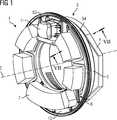
In
Vorzugsweise bildet der Hohlkörper
In einer vorteilhaften Ausgestaltung der Erfindung weist der Hohlkörper
Der Rotor
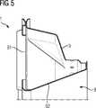
In
Vorzugsweise weist der Rotor
Die
Die
Das zumindest eine flächige Teil
Durch Wahl einer entsprechenden Krümmung und Stützung des zumindest einen flächigen Teils
Auf diese Weise ist die Steifigkeit und Festigkeit des Rotors
Räumliche Spannungsverläufe und die zur Minimierung der Biege- und Torsionsspannungen erforderliche Krümmung und Stützung des zumindest einen flächigen Teils
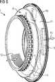
In
Der Hohlkörper
In
In einer vorteilhaften Ausgestaltung der Erfindung weist der Hohlkörper
Somit können auf dem Rotor
Durch eine entsprechende Formung des zumindest einen flächigen Teils
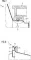
In
In
In
Zweckmäßigerweise ist das zumindest eine flächige Teil
In
ZITATE ENTHALTEN IN DER BESCHREIBUNG QUOTES INCLUDE IN THE DESCRIPTION
Diese Liste der vom Anmelder aufgeführten Dokumente wurde automatisiert erzeugt und ist ausschließlich zur besseren Information des Lesers aufgenommen. Die Liste ist nicht Bestandteil der deutschen Patent- bzw. Gebrauchsmusteranmeldung. Das DPMA übernimmt keinerlei Haftung für etwaige Fehler oder Auslassungen.This list of the documents listed by the applicant has been generated automatically and is included solely for the better information of the reader. The list is not part of the German patent or utility model application. The DPMA assumes no liability for any errors or omissions.
Zitierte PatentliteraturCited patent literature
- DE 102008036015 B4[0009]DE 102008036015 B4[0009]
Claims (19)
Translated fromGermanPriority Applications (3)
| Application Number | Priority Date | Filing Date | Title |
|---|---|---|---|
| DE102014217275.6ADE102014217275A1 (en) | 2014-08-29 | 2014-08-29 | Rotor for a gantry of a computed tomography device |
| CN201510526208.1ACN105380671A (en) | 2014-08-29 | 2015-08-25 | Rotor for a gantry of a computed tomograpy apparatus |
| US14/838,630US20160058398A1 (en) | 2014-08-29 | 2015-08-28 | Rotor for a gantry of a computed tomograpy apparatus |
Applications Claiming Priority (1)
| Application Number | Priority Date | Filing Date | Title |
|---|---|---|---|
| DE102014217275.6ADE102014217275A1 (en) | 2014-08-29 | 2014-08-29 | Rotor for a gantry of a computed tomography device |
Publications (1)
| Publication Number | Publication Date |
|---|---|
| DE102014217275A1true DE102014217275A1 (en) | 2016-03-03 |
Family
ID=55312051
Family Applications (1)
| Application Number | Title | Priority Date | Filing Date |
|---|---|---|---|
| DE102014217275.6AWithdrawnDE102014217275A1 (en) | 2014-08-29 | 2014-08-29 | Rotor for a gantry of a computed tomography device |
Country Status (3)
| Country | Link |
|---|---|
| US (1) | US20160058398A1 (en) |
| CN (1) | CN105380671A (en) |
| DE (1) | DE102014217275A1 (en) |
Families Citing this family (4)
| Publication number | Priority date | Publication date | Assignee | Title |
|---|---|---|---|---|
| CN105757870B (en)* | 2016-03-16 | 2020-02-07 | 上海联影医疗科技有限公司 | Ventilation system and ventilation control method of medical imaging equipment |
| CN109820532A (en)* | 2019-02-01 | 2019-05-31 | 上海联影医疗科技有限公司 | CT equipment and its rotatable support structure |
| DE102021201160A1 (en)* | 2021-02-08 | 2022-08-11 | Siemens Healthcare Gmbh | Gantry frame for a computed tomography system |
| CN217827894U (en)* | 2022-05-30 | 2022-11-18 | 上海西门子医疗器械有限公司 | Double-source CT machine and turntable for same |
Citations (6)
| Publication number | Priority date | Publication date | Assignee | Title |
|---|---|---|---|---|
| JP2007037873A (en)* | 2005-08-05 | 2007-02-15 | Hitachi Medical Corp | X-ray ct equipment |
| DE102008036015A1 (en)* | 2008-08-01 | 2010-02-11 | Siemens Aktiengesellschaft | Rotor for a gantry of a computed tomography device and computed tomography device with such a rotor |
| DE102012217739A1 (en)* | 2012-09-28 | 2014-04-03 | Siemens Ag | Cooling device for gantry of computer tomography, The rotor has refrigerant line which is integrated in rotating frame that is rotatably mounted relative to gantry housing |
| US8770839B2 (en)* | 2010-03-19 | 2014-07-08 | Mobius Imaging, Llc | Diagnostic imaging apparatus with airflow cooling system |
| DE102014204767A1 (en)* | 2013-03-15 | 2014-09-18 | Siemens Aktiengesellschaft | Diagnostic scanning device |
| DE102013205606A1 (en)* | 2013-03-28 | 2014-10-02 | Siemens Aktiengesellschaft | computed tomography scanner |
Family Cites Families (33)
| Publication number | Priority date | Publication date | Assignee | Title |
|---|---|---|---|---|
| US2990112A (en)* | 1959-05-28 | 1961-06-27 | Gen Motors Corp | Ventilating means |
| US4736075A (en)* | 1985-03-04 | 1988-04-05 | Picker International Inc. | Brake method and apparatus |
| US4969167A (en)* | 1988-11-25 | 1990-11-06 | Picker International, Inc. | CT scanner cooling duct |
| US5438605A (en)* | 1992-01-06 | 1995-08-01 | Picker International, Inc. | Ring tube x-ray source with active vacuum pumping |
| US5448608A (en)* | 1994-02-08 | 1995-09-05 | Analogic Corporation | Tomographic scanner having center of rotation for all physics |
| US5761269A (en)* | 1995-08-29 | 1998-06-02 | Kabushiki Kaisha Toshiba | X-ray computerized tomography system having cooling features |
| US6188743B1 (en)* | 1997-10-10 | 2001-02-13 | Analogic Corporation | Computed tomography scanner drive system and bearing |
| AT408997B (en)* | 2000-04-03 | 2002-04-25 | Andritz Ag Maschf | SORTERS FOR PAPER PRODUCTION AND WINGS FOR SORTERS |
| US7072434B1 (en)* | 2003-01-16 | 2006-07-04 | Analogic Corporation | Carry-on baggage tomography scanning system |
| DE10304661B4 (en)* | 2003-02-05 | 2007-03-01 | Siemens Ag | Cooling system and method for cooling a gantry |
| US7514885B2 (en)* | 2005-03-08 | 2009-04-07 | General Electric Company | Methods and systems for medical imaging |
| DE102005050634B4 (en)* | 2005-10-20 | 2012-01-05 | Siemens Ag | Device for a gantry of a tomography device and use of the device |
| DE102006037543B4 (en)* | 2006-08-10 | 2009-08-27 | Aerolas Gmbh, Aerostatische Lager- Lasertechnik | Device with a directly driven rotary body and aerostatic bearing |
| DE102007037313B4 (en)* | 2007-08-08 | 2009-11-12 | Siemens Ag | Computed tomography device with a gantry for holding components of a recording system rotatably arranged about a system axis |
| WO2009081327A2 (en)* | 2007-12-19 | 2009-07-02 | Koninklijke Philips Electronics N.V. | A rotor and x-ray ct scanners |
| JP5148331B2 (en)* | 2008-03-14 | 2013-02-20 | 株式会社東芝 | X-ray CT system |
| JP5348940B2 (en)* | 2008-05-09 | 2013-11-20 | 株式会社東芝 | X-ray computed tomography system |
| DE102008036016B4 (en)* | 2008-08-01 | 2012-01-05 | Siemens Aktiengesellschaft | Rotor, gantry and computer tomography device with a rotor on which components of a receiving device are mounted |
| DE102008041151B4 (en)* | 2008-08-11 | 2012-11-08 | Schleifring Und Apparatebau Gmbh | CT scanner gantry with aerostatic bearing and segmented ring motor |
| JP5203873B2 (en)* | 2008-09-29 | 2013-06-05 | 株式会社東芝 | Medical X-ray CT system |
| CN102308674B (en)* | 2009-01-09 | 2016-01-20 | 皇家飞利浦电子股份有限公司 | Imaging system gantry |
| CN102395319B (en)* | 2009-04-16 | 2014-05-14 | 株式会社日立医疗器械 | X-ray ct device |
| US8270563B2 (en)* | 2010-02-09 | 2012-09-18 | Aktiebolaget Skf | Diagnostic scanning apparatus |
| US8631982B2 (en)* | 2010-02-26 | 2014-01-21 | Robert Anthony Vicente | Safe attached to the hitch of a vehicle |
| CN103732145B (en)* | 2011-08-05 | 2016-08-17 | 东芝电子管器件株式会社 | Cooler, X ray computer tomography device and the maintenance method of X ray computer tomography device |
| JP2013121394A (en)* | 2011-12-09 | 2013-06-20 | Toshiba Corp | Holding apparatus and x-ray diagnostic apparatus |
| CN104010574B (en)* | 2011-12-20 | 2017-03-01 | 皇家飞利浦有限公司 | Imaging system gantry |
| DE102012201485B4 (en)* | 2012-02-02 | 2019-02-21 | Siemens Healthcare Gmbh | A medical imaging device having a casing shell having a casing shell, and a method of manufacturing a casing shell of the medical imaging device |
| JP5159965B1 (en)* | 2012-02-22 | 2013-03-13 | 株式会社東芝 | X-ray CT system |
| JP6338570B2 (en)* | 2012-04-16 | 2018-06-06 | ニューロロジカ・コーポレーション | Imaging system with fixedly mounted reference markers |
| CN102648859B (en)* | 2012-05-28 | 2014-06-25 | 苏州生物医学工程技术研究所 | X-ray computed tomography (CT) machine |
| CN203524687U (en)* | 2013-07-09 | 2014-04-09 | 上海西门子医疗器械有限公司 | Tilted rack, rotating disc, and CT rack component of CT machine, and CT machine |
| US9254108B2 (en)* | 2014-03-18 | 2016-02-09 | General Electric Company | Gantry with bore safety mechanism |
- 2014
- 2014-08-29DEDE102014217275.6Apatent/DE102014217275A1/ennot_activeWithdrawn
- 2015
- 2015-08-25CNCN201510526208.1Apatent/CN105380671A/enactivePending
- 2015-08-28USUS14/838,630patent/US20160058398A1/ennot_activeAbandoned
Patent Citations (7)
| Publication number | Priority date | Publication date | Assignee | Title |
|---|---|---|---|---|
| JP2007037873A (en)* | 2005-08-05 | 2007-02-15 | Hitachi Medical Corp | X-ray ct equipment |
| DE102008036015A1 (en)* | 2008-08-01 | 2010-02-11 | Siemens Aktiengesellschaft | Rotor for a gantry of a computed tomography device and computed tomography device with such a rotor |
| DE102008036015B4 (en) | 2008-08-01 | 2011-02-24 | Siemens Aktiengesellschaft | Rotor for a gantry of a computed tomography device and computed tomography device with such a rotor |
| US8770839B2 (en)* | 2010-03-19 | 2014-07-08 | Mobius Imaging, Llc | Diagnostic imaging apparatus with airflow cooling system |
| DE102012217739A1 (en)* | 2012-09-28 | 2014-04-03 | Siemens Ag | Cooling device for gantry of computer tomography, The rotor has refrigerant line which is integrated in rotating frame that is rotatably mounted relative to gantry housing |
| DE102014204767A1 (en)* | 2013-03-15 | 2014-09-18 | Siemens Aktiengesellschaft | Diagnostic scanning device |
| DE102013205606A1 (en)* | 2013-03-28 | 2014-10-02 | Siemens Aktiengesellschaft | computed tomography scanner |
Also Published As
| Publication number | Publication date |
|---|---|
| US20160058398A1 (en) | 2016-03-03 |
| CN105380671A (en) | 2016-03-09 |
Similar Documents
| Publication | Publication Date | Title |
|---|---|---|
| DE102006037543B4 (en) | Device with a directly driven rotary body and aerostatic bearing | |
| DE102014217275A1 (en) | Rotor for a gantry of a computed tomography device | |
| DE102013227060B4 (en) | Rotating frame for the gantry of a computer tomograph, as well as gantry and computer tomograph with such a rotating frame | |
| DE102008036015B4 (en) | Rotor for a gantry of a computed tomography device and computed tomography device with such a rotor | |
| DE202006020464U1 (en) | Roller bearings, in particular center-free slewing bearings | |
| DE102009052627B4 (en) | A scattered radiation collimator and method of making a scattered radiation collimator | |
| DE102014218462A1 (en) | Method for producing a collimator module and method for producing a collimator bridge as well as collimator module, collimator bridge, collimator and tomography device | |
| DE102008036016B4 (en) | Rotor, gantry and computer tomography device with a rotor on which components of a receiving device are mounted | |
| DE102016206428A1 (en) | Method and device for controlling a turntable | |
| DE102011086090A1 (en) | C-arm system | |
| DE102008021884A1 (en) | Tapered roller bearing and shaft bearing for at least one tapered roller bearing | |
| DE102008036014B4 (en) | Rotor for a gantry for a computed tomography device and manufacturing method for such a rotor | |
| DE102019121276A1 (en) | Fiber-reinforced plastic element | |
| DE202014000094U1 (en) | pressing device | |
| DE102011081167A1 (en) | Rear projection of a projection image data set with depth-dependent filtering | |
| DE102008036019A1 (en) | Computed tomography device and rotor for a gantry of a computed tomography device | |
| DE102007012167A1 (en) | Drill-elastic and rigid rod member for supporting and guiding a movable flap against a wing of an aircraft | |
| DE102014217569A1 (en) | Collimator module, detector module and method for producing a collimator module | |
| DE102015208905A1 (en) | Method for generating an image | |
| DE102013221726A1 (en) | High-strength frame for the rotatable bearing ring of a computer tomography device and bearing ring and computer tomography device with such a frame | |
| DE102008036017A1 (en) | Rotor and manufacturing method for a rotor of a gantry of a computer tomography device | |
| DE3204472A1 (en) | Rotary bending machine | |
| DE102014200445A1 (en) | pressing device | |
| DE102013007447A1 (en) | Wheel disc for a rail vehicle | |
| DE515424C (en) | Protective cover for the hinge point of two shafts connected to one another by a universal joint, in particular of motor vehicles |
Legal Events
| Date | Code | Title | Description |
|---|---|---|---|
| R012 | Request for examination validly filed | ||
| R016 | Response to examination communication | ||
| R081 | Change of applicant/patentee | Owner name:SIEMENS HEALTHCARE GMBH, DE Free format text:FORMER OWNER: SIEMENS AKTIENGESELLSCHAFT, 80333 MUENCHEN, DE | |
| R119 | Application deemed withdrawn, or ip right lapsed, due to non-payment of renewal fee |