DE102014208228A1 - Galvanic element and method for its production - Google Patents
Galvanic element and method for its productionDownload PDFInfo
- Publication number
- DE102014208228A1 DE102014208228A1DE102014208228.5ADE102014208228ADE102014208228A1DE 102014208228 A1DE102014208228 A1DE 102014208228A1DE 102014208228 ADE102014208228 ADE 102014208228ADE 102014208228 A1DE102014208228 A1DE 102014208228A1
- Authority
- DE
- Germany
- Prior art keywords
- cathode
- separator
- anode
- lithium
- galvanic element
- Prior art date
- Legal status (The legal status is an assumption and is not a legal conclusion. Google has not performed a legal analysis and makes no representation as to the accuracy of the status listed.)
- Withdrawn
Links
- 238000004519manufacturing processMethods0.000titleclaimsabstractdescription11
- 238000000034methodMethods0.000titleclaimsdescription31
- 239000004020conductorSubstances0.000claimsabstractdescription36
- 229910052744lithiumInorganic materials0.000claimsabstractdescription29
- WHXSMMKQMYFTQS-UHFFFAOYSA-NLithiumChemical compound[Li]WHXSMMKQMYFTQS-UHFFFAOYSA-N0.000claimsabstractdescription27
- 239000010406cathode materialSubstances0.000claimsabstractdescription13
- OKTJSMMVPCPJKN-UHFFFAOYSA-NCarbonChemical compound[C]OKTJSMMVPCPJKN-UHFFFAOYSA-N0.000claimsdescription16
- 239000000463materialSubstances0.000claimsdescription16
- 239000006182cathode active materialSubstances0.000claimsdescription15
- 238000000576coating methodMethods0.000claimsdescription9
- 239000002131composite materialSubstances0.000claimsdescription9
- 229910052751metalInorganic materials0.000claimsdescription7
- 239000002184metalSubstances0.000claimsdescription7
- 239000000203mixtureSubstances0.000claimsdescription7
- 239000010439graphiteSubstances0.000claimsdescription6
- 229910002804graphiteInorganic materials0.000claimsdescription6
- NINIDFKCEFEMDL-UHFFFAOYSA-NSulfurChemical compound[S]NINIDFKCEFEMDL-UHFFFAOYSA-N0.000claimsdescription5
- 239000011248coating agentSubstances0.000claimsdescription5
- 239000002223garnetSubstances0.000claimsdescription5
- 229910052717sulfurInorganic materials0.000claimsdescription5
- 239000011593sulfurSubstances0.000claimsdescription5
- 239000000443aerosolSubstances0.000claimsdescription4
- 239000003792electrolyteSubstances0.000claimsdescription3
- 230000008569processEffects0.000claimsdescription3
- 239000002041carbon nanotubeSubstances0.000claimsdescription2
- 229910021393carbon nanotubeInorganic materials0.000claimsdescription2
- 230000008020evaporationEffects0.000claimsdescription2
- 238000001704evaporationMethods0.000claimsdescription2
- 229910021389grapheneInorganic materials0.000claimsdescription2
- 229910000314transition metal oxideInorganic materials0.000claimsdescription2
- 235000010469Glycine maxNutrition0.000claims1
- 244000068988Glycine maxSpecies0.000claims1
- 239000004698PolyethyleneSubstances0.000claims1
- 229910001416lithium ionInorganic materials0.000description20
- HBBGRARXTFLTSG-UHFFFAOYSA-NLithium ionChemical compound[Li+]HBBGRARXTFLTSG-UHFFFAOYSA-N0.000description14
- 238000004806packaging method and processMethods0.000description8
- 229910052782aluminiumInorganic materials0.000description7
- 239000000919ceramicSubstances0.000description7
- XAGFODPZIPBFFR-UHFFFAOYSA-NaluminiumChemical compound[Al]XAGFODPZIPBFFR-UHFFFAOYSA-N0.000description6
- 229910052799carbonInorganic materials0.000description6
- 239000011244liquid electrolyteSubstances0.000description6
- 238000006243chemical reactionMethods0.000description5
- 239000011888foilSubstances0.000description5
- 239000010416ion conductorSubstances0.000description5
- 239000000843powderSubstances0.000description5
- 229910052802copperInorganic materials0.000description4
- 239000010949copperSubstances0.000description4
- 229910052742ironInorganic materials0.000description4
- 229910052759nickelInorganic materials0.000description4
- 239000007787solidSubstances0.000description4
- RYGMFSIKBFXOCR-UHFFFAOYSA-NCopperChemical compound[Cu]RYGMFSIKBFXOCR-UHFFFAOYSA-N0.000description3
- 229910018091Li 2 SInorganic materials0.000description3
- -1salt lithium hexa-fluorophosphateChemical class0.000description3
- KRHYYFGTRYWZRS-UHFFFAOYSA-MFluoride anionChemical compound[F-]KRHYYFGTRYWZRS-UHFFFAOYSA-M0.000description2
- 229910019142PO4Inorganic materials0.000description2
- 229920003171Poly (ethylene oxide)Polymers0.000description2
- 239000011149active materialSubstances0.000description2
- 230000009172burstingEffects0.000description2
- 238000007599dischargingMethods0.000description2
- 229910052748manganeseInorganic materials0.000description2
- VNWKTOKETHGBQD-UHFFFAOYSA-NmethaneChemical compoundCVNWKTOKETHGBQD-UHFFFAOYSA-N0.000description2
- 239000002105nanoparticleSubstances0.000description2
- 235000021317phosphateNutrition0.000description2
- 239000007858starting materialSubstances0.000description2
- BUHVIAUBTBOHAG-FOYDDCNASA-N(2r,3r,4s,5r)-2-[6-[[2-(3,5-dimethoxyphenyl)-2-(2-methylphenyl)ethyl]amino]purin-9-yl]-5-(hydroxymethyl)oxolane-3,4-diolChemical compoundCOC1=CC(OC)=CC(C(CNC=2C=3N=CN(C=3N=CN=2)[C@H]2[C@@H]([C@H](O)[C@@H](CO)O2)O)C=2C(=CC=CC=2)C)=C1BUHVIAUBTBOHAG-FOYDDCNASA-N0.000description1
- 229910018072Al 2 O 3Inorganic materials0.000description1
- 229910016569AlF 3Inorganic materials0.000description1
- PXGOKWXKJXAPGV-UHFFFAOYSA-NFluorineChemical compoundFFPXGOKWXKJXAPGV-UHFFFAOYSA-N0.000description1
- 239000005279LLTO - Lithium Lanthanum Titanium OxideSubstances0.000description1
- 229910004043Li(Ni0.5Mn1.5)O4Inorganic materials0.000description1
- 229910015118LiMOInorganic materials0.000description1
- 229910013275LiMPOInorganic materials0.000description1
- 229910015643LiMn 2 O 4Inorganic materials0.000description1
- 229910013870LiPF 6Inorganic materials0.000description1
- 229910006025NiCoMnInorganic materials0.000description1
- 239000002033PVDF binderSubstances0.000description1
- UCKMPCXJQFINFW-UHFFFAOYSA-NSulphideChemical compound[S-2]UCKMPCXJQFINFW-UHFFFAOYSA-N0.000description1
- 230000009471actionEffects0.000description1
- 239000006183anode active materialSubstances0.000description1
- 230000000712assemblyEffects0.000description1
- 238000000429assemblyMethods0.000description1
- 239000011324beadSubstances0.000description1
- 239000011230binding agentSubstances0.000description1
- 150000001642boronic acid derivativesChemical class0.000description1
- 229910010293ceramic materialInorganic materials0.000description1
- 229910052804chromiumInorganic materials0.000description1
- 239000002322conducting polymerSubstances0.000description1
- 229920001940conductive polymerPolymers0.000description1
- 239000011889copper foilSubstances0.000description1
- 230000008021depositionEffects0.000description1
- 238000009792diffusion processMethods0.000description1
- 238000004090dissolutionMethods0.000description1
- 239000002019doping agentSubstances0.000description1
- 238000004146energy storageMethods0.000description1
- 229910052731fluorineInorganic materials0.000description1
- 239000011737fluorineSubstances0.000description1
- 229910052733galliumInorganic materials0.000description1
- 229910052738indiumInorganic materials0.000description1
- 229910000664lithium aluminum titanium phosphates (LATP)Inorganic materials0.000description1
- 229910000625lithium cobalt oxideInorganic materials0.000description1
- 229910021450lithium metal oxideInorganic materials0.000description1
- BFZPBUKRYWOWDV-UHFFFAOYSA-Nlithium;oxido(oxo)cobaltChemical compound[Li+].[O-][Co]=OBFZPBUKRYWOWDV-UHFFFAOYSA-N0.000description1
- 239000011159matrix materialSubstances0.000description1
- 229910001512metal fluorideInorganic materials0.000description1
- 229910052987metal hydrideInorganic materials0.000description1
- 150000004681metal hydridesChemical class0.000description1
- 229910052976metal sulfideInorganic materials0.000description1
- 230000005012migrationEffects0.000description1
- 238000013508migrationMethods0.000description1
- 238000012986modificationMethods0.000description1
- 230000004048modificationEffects0.000description1
- 229910052750molybdenumInorganic materials0.000description1
- 150000004767nitridesChemical class0.000description1
- 239000000615nonconductorSubstances0.000description1
- 239000003960organic solventSubstances0.000description1
- 239000002245particleSubstances0.000description1
- NBIIXXVUZAFLBC-UHFFFAOYSA-KphosphateChemical compound[O-]P([O-])([O-])=ONBIIXXVUZAFLBC-UHFFFAOYSA-K0.000description1
- 239000010452phosphateSubstances0.000description1
- 150000003013phosphoric acid derivativesChemical class0.000description1
- 229920002239polyacrylonitrilePolymers0.000description1
- 229920001021polysulfidePolymers0.000description1
- 239000005077polysulfideSubstances0.000description1
- 150000008117polysulfidesPolymers0.000description1
- 238000002360preparation methodMethods0.000description1
- 238000003825pressingMethods0.000description1
- 230000001681protective effectEffects0.000description1
- 230000009257reactivityEffects0.000description1
- 229910052707rutheniumInorganic materials0.000description1
- 229910052706scandiumInorganic materials0.000description1
- 238000007086side reactionMethods0.000description1
- 150000004760silicatesChemical class0.000description1
- 239000000758substrateSubstances0.000description1
- 239000002203sulfidic glassSubstances0.000description1
- 238000004381surface treatmentMethods0.000description1
- 230000008646thermal stressEffects0.000description1
- 229910052718tinInorganic materials0.000description1
- 229910052720vanadiumInorganic materials0.000description1
- 238000007740vapor depositionMethods0.000description1
Images
Classifications
- H—ELECTRICITY
- H01—ELECTRIC ELEMENTS
- H01M—PROCESSES OR MEANS, e.g. BATTERIES, FOR THE DIRECT CONVERSION OF CHEMICAL ENERGY INTO ELECTRICAL ENERGY
- H01M4/00—Electrodes
- H01M4/02—Electrodes composed of, or comprising, active material
- H01M4/04—Processes of manufacture in general
- H01M4/0438—Processes of manufacture in general by electrochemical processing
- H01M4/044—Activating, forming or electrochemical attack of the supporting material
- H01M4/0445—Forming after manufacture of the electrode, e.g. first charge, cycling
- H01M4/0447—Forming after manufacture of the electrode, e.g. first charge, cycling of complete cells or cells stacks
- H—ELECTRICITY
- H01—ELECTRIC ELEMENTS
- H01M—PROCESSES OR MEANS, e.g. BATTERIES, FOR THE DIRECT CONVERSION OF CHEMICAL ENERGY INTO ELECTRICAL ENERGY
- H01M10/00—Secondary cells; Manufacture thereof
- H01M10/05—Accumulators with non-aqueous electrolyte
- H01M10/052—Li-accumulators
- H—ELECTRICITY
- H01—ELECTRIC ELEMENTS
- H01M—PROCESSES OR MEANS, e.g. BATTERIES, FOR THE DIRECT CONVERSION OF CHEMICAL ENERGY INTO ELECTRICAL ENERGY
- H01M10/00—Secondary cells; Manufacture thereof
- H01M10/05—Accumulators with non-aqueous electrolyte
- H01M10/052—Li-accumulators
- H01M10/0525—Rocking-chair batteries, i.e. batteries with lithium insertion or intercalation in both electrodes; Lithium-ion batteries
- H—ELECTRICITY
- H01—ELECTRIC ELEMENTS
- H01M—PROCESSES OR MEANS, e.g. BATTERIES, FOR THE DIRECT CONVERSION OF CHEMICAL ENERGY INTO ELECTRICAL ENERGY
- H01M10/00—Secondary cells; Manufacture thereof
- H01M10/05—Accumulators with non-aqueous electrolyte
- H01M10/056—Accumulators with non-aqueous electrolyte characterised by the materials used as electrolytes, e.g. mixed inorganic/organic electrolytes
- H01M10/0561—Accumulators with non-aqueous electrolyte characterised by the materials used as electrolytes, e.g. mixed inorganic/organic electrolytes the electrolyte being constituted of inorganic materials only
- H01M10/0562—Solid materials
- H—ELECTRICITY
- H01—ELECTRIC ELEMENTS
- H01M—PROCESSES OR MEANS, e.g. BATTERIES, FOR THE DIRECT CONVERSION OF CHEMICAL ENERGY INTO ELECTRICAL ENERGY
- H01M10/00—Secondary cells; Manufacture thereof
- H01M10/05—Accumulators with non-aqueous electrolyte
- H01M10/056—Accumulators with non-aqueous electrolyte characterised by the materials used as electrolytes, e.g. mixed inorganic/organic electrolytes
- H01M10/0564—Accumulators with non-aqueous electrolyte characterised by the materials used as electrolytes, e.g. mixed inorganic/organic electrolytes the electrolyte being constituted of organic materials only
- H01M10/0565—Polymeric materials, e.g. gel-type or solid-type
- H—ELECTRICITY
- H01—ELECTRIC ELEMENTS
- H01M—PROCESSES OR MEANS, e.g. BATTERIES, FOR THE DIRECT CONVERSION OF CHEMICAL ENERGY INTO ELECTRICAL ENERGY
- H01M10/00—Secondary cells; Manufacture thereof
- H01M10/42—Methods or arrangements for servicing or maintenance of secondary cells or secondary half-cells
- H01M10/44—Methods for charging or discharging
- H01M10/446—Initial charging measures
- H—ELECTRICITY
- H01—ELECTRIC ELEMENTS
- H01M—PROCESSES OR MEANS, e.g. BATTERIES, FOR THE DIRECT CONVERSION OF CHEMICAL ENERGY INTO ELECTRICAL ENERGY
- H01M4/00—Electrodes
- H01M4/02—Electrodes composed of, or comprising, active material
- H01M4/13—Electrodes for accumulators with non-aqueous electrolyte, e.g. for lithium-accumulators; Processes of manufacture thereof
- H01M4/131—Electrodes based on mixed oxides or hydroxides, or on mixtures of oxides or hydroxides, e.g. LiCoOx
- H—ELECTRICITY
- H01—ELECTRIC ELEMENTS
- H01M—PROCESSES OR MEANS, e.g. BATTERIES, FOR THE DIRECT CONVERSION OF CHEMICAL ENERGY INTO ELECTRICAL ENERGY
- H01M4/00—Electrodes
- H01M4/02—Electrodes composed of, or comprising, active material
- H01M4/13—Electrodes for accumulators with non-aqueous electrolyte, e.g. for lithium-accumulators; Processes of manufacture thereof
- H01M4/139—Processes of manufacture
- H01M4/1395—Processes of manufacture of electrodes based on metals, Si or alloys
- H—ELECTRICITY
- H01—ELECTRIC ELEMENTS
- H01M—PROCESSES OR MEANS, e.g. BATTERIES, FOR THE DIRECT CONVERSION OF CHEMICAL ENERGY INTO ELECTRICAL ENERGY
- H01M4/00—Electrodes
- H01M4/02—Electrodes composed of, or comprising, active material
- H01M4/36—Selection of substances as active materials, active masses, active liquids
- H01M4/362—Composites
- H01M4/364—Composites as mixtures
- H—ELECTRICITY
- H01—ELECTRIC ELEMENTS
- H01M—PROCESSES OR MEANS, e.g. BATTERIES, FOR THE DIRECT CONVERSION OF CHEMICAL ENERGY INTO ELECTRICAL ENERGY
- H01M4/00—Electrodes
- H01M4/02—Electrodes composed of, or comprising, active material
- H01M4/36—Selection of substances as active materials, active masses, active liquids
- H01M4/38—Selection of substances as active materials, active masses, active liquids of elements or alloys
- H01M4/381—Alkaline or alkaline earth metals elements
- H01M4/382—Lithium
- H—ELECTRICITY
- H01—ELECTRIC ELEMENTS
- H01M—PROCESSES OR MEANS, e.g. BATTERIES, FOR THE DIRECT CONVERSION OF CHEMICAL ENERGY INTO ELECTRICAL ENERGY
- H01M4/00—Electrodes
- H01M4/02—Electrodes composed of, or comprising, active material
- H01M4/62—Selection of inactive substances as ingredients for active masses, e.g. binders, fillers
- H01M4/624—Electric conductive fillers
- H01M4/625—Carbon or graphite
- H—ELECTRICITY
- H01—ELECTRIC ELEMENTS
- H01M—PROCESSES OR MEANS, e.g. BATTERIES, FOR THE DIRECT CONVERSION OF CHEMICAL ENERGY INTO ELECTRICAL ENERGY
- H01M4/00—Electrodes
- H01M4/02—Electrodes composed of, or comprising, active material
- H01M2004/026—Electrodes composed of, or comprising, active material characterised by the polarity
- H01M2004/027—Negative electrodes
- H—ELECTRICITY
- H01—ELECTRIC ELEMENTS
- H01M—PROCESSES OR MEANS, e.g. BATTERIES, FOR THE DIRECT CONVERSION OF CHEMICAL ENERGY INTO ELECTRICAL ENERGY
- H01M2220/00—Batteries for particular applications
- H01M2220/30—Batteries in portable systems, e.g. mobile phone, laptop
- H—ELECTRICITY
- H01—ELECTRIC ELEMENTS
- H01M—PROCESSES OR MEANS, e.g. BATTERIES, FOR THE DIRECT CONVERSION OF CHEMICAL ENERGY INTO ELECTRICAL ENERGY
- H01M2300/00—Electrolytes
- H01M2300/0017—Non-aqueous electrolytes
- H01M2300/0065—Solid electrolytes
- H01M2300/0068—Solid electrolytes inorganic
- H01M2300/0071—Oxides
- H—ELECTRICITY
- H01—ELECTRIC ELEMENTS
- H01M—PROCESSES OR MEANS, e.g. BATTERIES, FOR THE DIRECT CONVERSION OF CHEMICAL ENERGY INTO ELECTRICAL ENERGY
- H01M2300/00—Electrolytes
- H01M2300/0017—Non-aqueous electrolytes
- H01M2300/0065—Solid electrolytes
- H01M2300/0082—Organic polymers
- Y—GENERAL TAGGING OF NEW TECHNOLOGICAL DEVELOPMENTS; GENERAL TAGGING OF CROSS-SECTIONAL TECHNOLOGIES SPANNING OVER SEVERAL SECTIONS OF THE IPC; TECHNICAL SUBJECTS COVERED BY FORMER USPC CROSS-REFERENCE ART COLLECTIONS [XRACs] AND DIGESTS
- Y02—TECHNOLOGIES OR APPLICATIONS FOR MITIGATION OR ADAPTATION AGAINST CLIMATE CHANGE
- Y02E—REDUCTION OF GREENHOUSE GAS [GHG] EMISSIONS, RELATED TO ENERGY GENERATION, TRANSMISSION OR DISTRIBUTION
- Y02E60/00—Enabling technologies; Technologies with a potential or indirect contribution to GHG emissions mitigation
- Y02E60/10—Energy storage using batteries
- Y—GENERAL TAGGING OF NEW TECHNOLOGICAL DEVELOPMENTS; GENERAL TAGGING OF CROSS-SECTIONAL TECHNOLOGIES SPANNING OVER SEVERAL SECTIONS OF THE IPC; TECHNICAL SUBJECTS COVERED BY FORMER USPC CROSS-REFERENCE ART COLLECTIONS [XRACs] AND DIGESTS
- Y02—TECHNOLOGIES OR APPLICATIONS FOR MITIGATION OR ADAPTATION AGAINST CLIMATE CHANGE
- Y02P—CLIMATE CHANGE MITIGATION TECHNOLOGIES IN THE PRODUCTION OR PROCESSING OF GOODS
- Y02P70/00—Climate change mitigation technologies in the production process for final industrial or consumer products
- Y02P70/50—Manufacturing or production processes characterised by the final manufactured product
- Y—GENERAL TAGGING OF NEW TECHNOLOGICAL DEVELOPMENTS; GENERAL TAGGING OF CROSS-SECTIONAL TECHNOLOGIES SPANNING OVER SEVERAL SECTIONS OF THE IPC; TECHNICAL SUBJECTS COVERED BY FORMER USPC CROSS-REFERENCE ART COLLECTIONS [XRACs] AND DIGESTS
- Y02—TECHNOLOGIES OR APPLICATIONS FOR MITIGATION OR ADAPTATION AGAINST CLIMATE CHANGE
- Y02T—CLIMATE CHANGE MITIGATION TECHNOLOGIES RELATED TO TRANSPORTATION
- Y02T10/00—Road transport of goods or passengers
- Y02T10/60—Other road transportation technologies with climate change mitigation effect
- Y02T10/70—Energy storage systems for electromobility, e.g. batteries
Landscapes
- Chemical & Material Sciences (AREA)
- Engineering & Computer Science (AREA)
- Chemical Kinetics & Catalysis (AREA)
- Electrochemistry (AREA)
- General Chemical & Material Sciences (AREA)
- Manufacturing & Machinery (AREA)
- Materials Engineering (AREA)
- Physics & Mathematics (AREA)
- Condensed Matter Physics & Semiconductors (AREA)
- General Physics & Mathematics (AREA)
- Inorganic Chemistry (AREA)
- Composite Materials (AREA)
- Dispersion Chemistry (AREA)
- Secondary Cells (AREA)
- Battery Electrode And Active Subsutance (AREA)
Abstract
Translated fromGermanDescription
Translated fromGermanDie Erfindung betrifft ein galvanisches Element und ein Verfahren zum Herstellen eines solchen galvanischen Elements, wobei das galvanische Element einen der Anode zugeordneten Stromableiter, eine Anode, einen Separator, eine Kathode sowie einen der Kathode zugeordneten Stromableiter umfasst. Des Weiteren betrifft die Erfindung eine Batteriezelle umfassend ein solches galvanisches Element sowie eine Batterie umfassend mehrere solcher Batteriezellen.The invention relates to a galvanic element and a method for producing such a galvanic element, wherein the galvanic element comprises a current collector associated with the anode, an anode, a separator, a cathode and a current conductor associated with the cathode. Furthermore, the invention relates to a battery cell comprising such a galvanic element and a battery comprising a plurality of such battery cells.
Stand der TechnikState of the art
Lithium-Ionen-Batterien zeichnen sich unter anderem durch eine sehr hohe spezifische Energie und eine äußerst geringe Selbstentladung aus. Lithium-Ionen-Zellen besitzen mindestens eine positive und mindestens eine negative Elektrode (Kathode bzw. Anode), wobei während des Ladens und Entladens der Batterie Lithium-Ionen von einer Elektrode zur anderen Elektrode wandern. Für den Transport der Lithium-Ionen ist ein sogenannter Lithium-Ionen-Leiter notwendig. Bei den derzeit verwendeten Lithium-Ionen-Zellen, die beispielsweise im Consumer-Bereich (Mobiltelefon, MP3 Player, usw.) oder als Energiespeicher in Elektro- oder Hybridfahrzeugen zum Einsatz kommen, ist der Lithium-Ionen-Leiter ein Flüssig-Elektrolyt, welcher häufig das Lithium-Leitsalz Lithium-Hexa-Fluorophosphat (LiPF6) in organischen Lösemitteln gelöst enthält. Eine Lithium-Ionen-Zelle umfasst die Elektroden, den Lithium-Ionen-Leiter sowie Stromableiter, die die elektrischen Anschlüsse herstellen.Among other things, lithium-ion batteries are characterized by a very high specific energy and extremely low self-discharge. Lithium-ion cells have at least one positive and at least one negative electrode (cathode or anode), wherein during charging and discharging of the battery, lithium ions migrate from one electrode to the other electrode. For the transport of lithium ions, a so-called lithium-ion conductor is necessary. In the lithium-ion cells currently used, which are used for example in the consumer sector (mobile phone, MP3 player, etc.) or as energy storage in electric or hybrid vehicles, the lithium-ion conductor is a liquid electrolyte, which often contains the lithium-conducting salt lithium hexa-fluorophosphate (LiPF6 ) dissolved in organic solvents. A lithium-ion cell includes the electrodes, the lithium-ion conductor and current conductors that make the electrical connections.
Die Lithium-Ionen-Zellen können in einer Verpackung eingeschlossen sein. Als Verpackung kommen beispielsweise Aluminium-Verbundfolien zum Einsatz. So verpackte Zellen werden wegen ihrer weichen Verpackung auch als Pouch bzw. Softpack bezeichnet. Neben dem Softpack-Verpackungsdesign kommen als Verpackungen auch feste Metallgehäuse zum Einsatz, zum Beispiel in Form von tiefgezogenen oder fließgepressten Gehäuseteilen. In diesem Fall spricht man von festem Gehäuse oder Hardcase.The lithium-ion cells may be enclosed in a package. For example, aluminum composite films are used as packaging. So packaged cells are also referred to as a pouch or soft pack because of their soft packaging. In addition to softpack packaging design, solid metal housings are also used as packaging, for example in the form of deep-drawn or extruded housing parts. In this case we speak of a solid housing or hardcase.
Nachteilig an Lithium-Ionen-Zellen mit Flüssig-Elektrolyt ist, dass sich bei mechanischem und thermischem Stress die Flüssig-Elektrolyt-Komponente zersetzen kann und ein Überdruck in der Zelle entsteht. Ohne entsprechende Schutzmaßnahmen kann dies zum Bersten oder sogar zum Brennen der Zelle führen.A disadvantage of lithium-ion cells with liquid electrolyte is that under mechanical and thermal stress, the liquid-electrolyte component can decompose and creates an overpressure in the cell. Without appropriate protective measures, this can lead to bursting or even burning of the cell.
Es ist möglich, anstelle eines flüssigen Elektrolyten einen festen keramischen bzw. anorganischen Lithium-Ionen-Leiter zu verwenden. Durch dieses Konzept wird das Bersten der Batteriezelle oder ein Auslaufen von Stoffen bei Beschädigung der Verpackung vermieden.It is possible to use a solid ceramic or inorganic lithium-ion conductor instead of a liquid electrolyte. This concept avoids bursting of the battery cell or leakage of materials when the packaging is damaged.
Aus
Nachteilig an der Verwendung einer Graphitanode ist ihre vergleichsweise geringe Energiedichte im Vergleich zu einer auf Lithium-Metall-basierenden Anode. Lithium-Metall-basierende Anoden wiederum sind bei der Herstellung eines galvanischen Elements schwer zu handhaben, da das Lithium eine hohe Reaktivität aufweist und nur in völlig trockenen Umgebungen stabil ist.A disadvantage of the use of a graphite anode is its comparatively low energy density in comparison to a lithium-metal-based anode. In turn, lithium-metal based anodes are difficult to handle in the fabrication of a galvanic element because the lithium has high reactivity and is stable only in completely dry environments.
Offenbarung der ErfindungDisclosure of the invention
Es wird ein Verfahren zum Herstellen eines galvanischen Elements vorgeschlagen, welches folgende Schritte umfasst:
- a) Herstellen einer Schichtfolge umfassend in dieser Reihenfolge einen einer Anode zugeordneten Stromableiter, einen Ionen-leitenden und elektrisch isolierenden Separator, eine Kathode mit Lithium enthaltendem Kathodenmaterial und einen der Kathode zugeordneten Stromableiter, und
- b) Aufladen des galvanischen Elements,
- a) producing a layer sequence comprising, in this order, an anode conductor associated with an anode, an ion-conducting and electrically insulating separator, a cathode with lithium-containing cathode material and a current collector associated with the cathode, and
- b) charging the galvanic element,
Die Schichtfolge kann beispielsweise hergestellt werden, indem in einem ersten Schritt i) der der Anode zugeordnete Stromableiter bereitgestellt wird. In einem zweiten Schritt ii) wird auf dem der Anode zugeordneten Stromableiter der Ionen-leitende und elektrisch isolierende Separator aufgebracht. In einem dritten Schritt wird dann die Kathode mit Lithium enthaltendem Kathodenmaterial auf dem Separator aufgebracht. In einem letzten Schritt iv) wird dann der der Kathode zugeordnete Stromableiter auf der Kathode angeordnet.The layer sequence can be produced, for example, by providing, in a first step i), the current conductor assigned to the anode. In a second step ii), the ion-conducting and electrically insulating separator is applied to the current conductor associated with the anode. In a third step, the cathode is then applied to the separator with lithium-containing cathode material. In a final step iv) then the the cathode associated with arranged on the cathode current collector.
Im ersten Schritt i) der Herstellung der Schichtfolge wird der der Anode zugeordnete Stromableiter bereitgestellt. Die Stromableiter sind typischerweise als Metallfolien ausgeführt, wobei für den der Anode zugeordneten Stromableiter typischerweise Kupferfolien mit Dicken zwischen 6 µm und 12 µm eingesetzt werden. Denkbar wäre auch der Einsatz von anderen Materialien als Träger, auf den eine Kupferschicht aufgebracht wird. Üblicherweise wird die der Anode zugewandte Seite des Stromableiters einer Oberflächenbehandlung unterzogen, um eine Reaktion mit metallischem Lithium zu unterbinden.In the first step i) the production of the layer sequence of the anode associated with the current conductor is provided. The current conductors are typically designed as metal foils, wherein copper conductors with thicknesses between 6 .mu.m and 12 .mu.m are typically used for the current conductor associated with the anode. It would also be conceivable to use materials other than supports on which a copper layer is applied. Typically, the anode-facing side of the current collector is surface-treated to prevent reaction with metallic lithium.
Im zweiten Schritt ii) der Herstellung der Schichtfolge wird der Ionen-leitende und elektrisch isolierende Separator auf den der Anode zugeordneten Stromableiter in Form einer Schicht aufgetragen. Die Schicht wird bevorzugt geschlossen ausgeführt. Das Material des Separators ist bevorzugt ein keramisches Material, welches in einer Ausführungsform des Verfahrens in Form eines keramischen Pulvers mittels Aerosolbeschichtung aufgebracht wird. Ein geeignetes Verfahren kann beispielsweise der
Das Material des Separators ist bevorzugt eine Lithium-leitende Keramik. Insbesondere ist als Material für den Separator Lithium-Granat geeignet. Alternativ kann das Material des Separators ausgewählt sein aus Perovskite (LLTO) Li3xLa2/3 – xTiO3, Phosphate (LATP) Li1 + xTi2 – xMx(PO4)3 (wobei M = Al, Ga, In oder Sc), sulfidische Gläser enthaltend Li2S und P2S5 sowie Dotierelemente wie Ge und Sn und Argyrodite Li6PS5X (wobei X = I, Cl oder Br).The material of the separator is preferably a lithium-conductive ceramic. In particular, is suitable as a material for the separator lithium garnet. Alternatively, the material of the separator may be selected from perovskites (LLTO) Li3xLa2 / 3 - x TiO3, phosphate (LATP) Li1 + xTi2 - x M x (PO 4) 3 (where M = Al, Ga, In or Sc), sulfide glasses containing Li2 S and P2 S5 and dopants such as Ge and Sn and Argyrodite Li6 PS5 X (where X = I, Cl or Br).
Im dritten Schritt iii) der Herstellung der Schichtfolge wird auf den Separator eine Kathode in Form einer Schicht aus einem Lithium enthaltendem Kathodenmaterial aufgebracht. Das Kathodenmaterial kann beispielsweise zu einer Paste oder zu einem Schlicker aufbereitet werden, die auf den Separator aufgetragen werden. Auch andere dem Fachmann bekannte Beschichtungsverfahren können verwendet werden.In the third step iii) of the production of the layer sequence, a cathode in the form of a layer of a lithium-containing cathode material is applied to the separator. For example, the cathode material may be made into a paste or slip which is applied to the separator. Other coating methods known to the person skilled in the art can also be used.
Das Kathodenmaterial ist bevorzugt eine Mischung aus einem gegebenenfalls. prälithiierten Kathodenaktivmaterial, einem elektrisch leitfähigen Material und einem ionisch leitfähigen Katholyten. Das Kathodenaktivmaterial kann in einer bevorzugten Ausführungsform als ein Kompositwerkstoff mit Kohlenstoff vorliegen, um die elektrische Leitfähigkeit zu erhöhen.The cathode material is preferably a mixture of one optionally. prelithiated cathode active material, an electrically conductive material and an ionically conductive catholyte. The cathode active material, in a preferred embodiment, may be present as a composite material with carbon to increase electrical conductivity.
Der Kompositwerkstoff umfasst in einer Ausführungsform des Verfahrens eine Mischung aus Schwefelpartikeln als Aktivmaterial, Graphit und Leitruß um die elektrische Leitfähigkeit zu erhöhen und ggf. einem Binder wie z. B. PVdF (Polyvinylidenfluorid). In einer weiteren Ausführungsform des Verfahrens umfasst das Kathodenaktivmaterial eine Mischung aus SPAN (Schwefelpolyacrylnitril), Graphit und/oder Leitruß und einem Lithium-ionenleitenden Polymer. In einer weiteren Ausführungsform umfasst der Kompositwerkstoff eine Mischung von gegebenenfalls Kohlenstoff sowie Nanopartikeln von LiF und einem Metall, wie z.B. Fe, Cu, Ni. In einer weiteren Ausführungsform umfasst der Kompositwerkstoff eine Mischung von gegebenenfalls Kohlenstoff sowie Nanopartikeln von Li2S und einem Metall, wie z.B. Fe, Cu, Ni. In einer anderen Ausführungsform ist die Prälithiierung des Metalls bereits erfolgt und der Kompositwerkstoff besteht aus Kohlenstoff und einem Li-haltigen Metallhydrid, -sulfid, -fluorid oder -nitrid.The composite material in one embodiment of the method comprises a mixture of sulfur particles as active material, graphite and Leitruß to increase the electrical conductivity and optionally a binder such. B. PVdF (polyvinylidene fluoride). In a further embodiment of the method, the cathode active material comprises a mixture of SPAN (sulfur polyacrylonitrile), graphite and / or conductive carbon black and a lithium ion-conducting polymer. In a further embodiment, the composite material comprises a mixture of optionally carbon and nanoparticles of LiF and a metal, such as Fe, Cu, Ni. In a further embodiment, the composite material comprises a mixture of optionally carbon and nanoparticles of Li2 S and a metal, such as Fe, Cu, Ni. In another embodiment, the prelialization of the metal has already taken place and the composite material consists of carbon and a Li-containing metal hydride, sulfide, fluoride or nitride.
Um eine Migration des Fluors und somit eine Reaktion mit dem Katholyt, eine Reaktion mit dem Stromableiter oder Reaktionen mit anderen Batteriekomponenten zu verhindern, ist der Kompositwerkstoff in bevorzugter Ausführung mit einem Coating versehen, z.B. aus Kohlenstoff oder einem Oxid (z.B. Al2O3) oder Fluorid (z.B. AlF3) oder Oxyflourid. Ein Coating kann auch die Diffusion von Polysulfiden in der schwefelhaltigen Ausführungsform verhindern.In order to prevent a migration of the fluorine and thus a reaction with the catholyte, a reaction with the current conductor or reactions with other battery components, the composite material is provided in a preferred embodiment with a coating, for example made of carbon or an oxide (eg Al2 O3 ) or fluoride (eg AlF3 ) or oxyflouride. Coating may also prevent the diffusion of polysulfides in the sulfur-containing embodiment.
In einer weiteren Ausführungsform des Verfahrens ist das Kathodenaktivmaterial ausgewählt aus einem lithiiertem Übergangsmetalloxid, beispielsweise Li(NiCoMn)O2, LiMn2O4 (oder höherer Li-Gehalt), Li2MO3-LiMO2 (wobei M beispielsweise Ni, Co, Mn, Mo, Cr, Fe, Ru oder V ist), LiMPO4 (wobei M beispielsweise Fe, Ni, Co oder Mn ist), Li(Ni0,5Mn1,5)O4 (oder höherer Li-Gehalt), LixV2O5, LixV3O8 oder weitere dem Fachmann bekannte Kathodenmaterialien wie Borate, Phosphate, Fluorophosphate, Silicate.In a further embodiment of the method, the cathode active material is selected from a lithiated transition metal oxide, for example Li (NiCoMn) O2 , LiMn2 O4 (or higher Li content), Li2 MO3 -LiMO2 (where M is, for example, Ni, Co, Mn, Mo, Cr, Fe, Ru or V), LiMPO4 (where M is, for example, Fe, Ni, Co or Mn), Li (Ni0.5 Mn1.5 ) O4 (or higher Li content) , Lix V2 O5 , LixV3 O8 or further cathode materials known to the person skilled in the art, such as borates, phosphates, fluorophosphates, silicates.
In einer weiteren Ausführungsform des Verfahrens ist das Kathodenaktivmaterial ausgewählt aus einem lithiiertem Schwefel, beispielsweise Li2S, wobei das Material bevorzugt in einer Kohlenstoffverbundmatrix, beispielsweise in Form kleiner Kügelchen, eingekapselt ist, um eine Auflösung oder Nebenreaktionen mit dem Katholyt zu verhindern.In a further embodiment of the method, the cathode active material is selected from a lithiated sulfur, for example Li2 S, wherein the material is preferably encapsulated in a carbon composite matrix, for example in the form of small beads, to prevent dissolution or side reactions with the catholyte.
In einer Ausführungsform des Verfahrens ist der Katholyt ein Elektrolyt auf Poylethylenoxid(PEO)-Basis oder auf Soja-Basis. In one embodiment of the method, the catholyte is a polyethylene oxide (PEO) -based or soy-based electrolyte.
Alternativ oder zusätzlich ist es denkbar, auch die für den Ionen-leitenden Separator verwendeten Materialien als Katholyt einzusetzen, da auch diese Materialien eine gute ionischen Leitfähigkeit aufweisen. Zusätzlich darf der Katholyt noch eine elektrische Leitfähigkeit haben, was jedoch nicht notwendigerweise der Fall sein mussAlternatively or additionally, it is also conceivable to use the materials used for the ion-conducting separator as catholyte, since these materials also have good ionic conductivity. In addition, the catholyte may still have an electrical conductivity, but this need not necessarily be the case
In einer Ausführungsform des Verfahrens ist das leitfähige Material ausgewählt aus Kohlenstoff-Nanoröhrchen, einem Leitruß, Graphene, Graphit oder einer Kombination mindestens zweier dieser Materialien.In one embodiment of the method, the conductive material is selected from carbon nanotubes, a conductive carbon black, graphene, graphite or a combination of at least two of these materials.
Im vierten Schritt iv) der Herstellung der Schichtfolge wird der der Kathode zugeordnete Stromableiter auf die Kathode aufgebracht. Der der Kathode zugeordnete Stromableiter kann wiederum als Metallfolie ausgeführt sein, wobei für die Kathode üblicherweise eine Aluminiumfolie mit einer Dicke zwischen 13 µm und 15 µm eingesetzt wird. Alternativ ist es wiederum denkbar, ein mit Aluminium beschichtetes Trägermaterial als den der Kathode zugeordneten Stromableiter einzusetzen. In einer weiteren Alternative wäre es denkbar, das Material für den der Kathode zugeordneten Stromableiter mit einem dem Fachmann bekannten Beschichtungsverfahren aufzutragen, beispielsweise mittels Aufdampfen.In the fourth step iv) the production of the layer sequence of the cathode associated with the current conductor is applied to the cathode. The current collector assigned to the cathode can in turn be in the form of a metal foil, wherein an aluminum foil with a thickness between 13 μm and 15 μm is usually used for the cathode. Alternatively, it is again conceivable to use a substrate coated with aluminum as the current conductor associated with the cathode. In a further alternative, it would be conceivable to apply the material for the current conductor associated with the cathode with a coating method known to the person skilled in the art, for example by means of vapor deposition.
Des Weiteren kann auch der der Kathode zugeordnete Stromableiter einer Oberflächenbehandlung unterzogen werden, um Reaktionen zwischen den im galvanischen Element enthaltenen Materialien und dem Material des Stromableiters, beispielsweise Aluminium, zu verhindern.Furthermore, the current conductor associated with the cathode can also be subjected to a surface treatment in order to prevent reactions between the materials contained in the galvanic element and the material of the current conductor, for example aluminum.
Je nach Ausführungsform des Verfahrens können die Schritte i) bis iv) auch in anderer Reihenfolge ausgeführt werden. So ist es beispielsweise denkbar, die Schritte i) und ii) separat durchführen, parallel dazu einen der Kathode zugeordneten Stromableiter bereitzustellen, auf diesem die Kathode aufzubringen und anschließend beide Komponenten zusammenzufügen.Depending on the embodiment of the method, the steps i) to iv) can also be carried out in a different order. Thus, it is conceivable, for example, to carry out steps i) and ii) separately, to provide a current conductor assigned to the cathode in parallel, to apply the cathode to the latter and then to join the two components together.
Anschließend kann das Aufladen gemäß Schritt b) als letzten Schritt vollzogen werden.Subsequently, the charging according to step b) can be completed as the last step.
Im zweiten und letzten Schritt b) des Verfahrens wird das im Schritt a) des Verfahrens erzeugte galvanische Element erstmalig elektrisch aufgeladen. Dabei wandern Lithium-Ionen aus dem Kathodenaktivmaterial in der Kathode durch den Ionen-leitenden Separator hindurch und lagern sich in Form einer Schicht aus metallischem Lithium auf die dem Separator zugewandten Seite des der Anode zugeordneten Stromableiters ab. Dadurch wird eine Anode umfassend metallisches Lithium zwischen dem der Anode zugeordneten Stromableiter und dem Separator ausgebildet.In the second and final step b) of the method, the galvanic element produced in step a) of the method is electrically charged for the first time. In this case, lithium ions migrate from the cathode active material in the cathode through the ion-conducting separator and are deposited in the form of a layer of metallic lithium on the side facing the separator of the current conductor associated with the anode. As a result, an anode comprising metallic lithium is formed between the current collector associated with the anode and the separator.
Des Weiteren wird eine Batteriezelle vorgeschlagen, umfassend eine Zellverpackung und ein galvanisches Element, das nach dem soeben beschriebenen Verfahren hergestellt ist. Bei der Zellverpackung kann es sich um ein Softpack-Verpackungsdesign oder um ein festes Gehäuse handeln.Furthermore, a battery cell is proposed, comprising a cell packaging and a galvanic element, which is manufactured according to the method just described. Cell packaging may be a soft pack packaging design or a solid housing.
Zudem wird eine Batterie umfassend eine oder mehrere solcher Batteriezellen vorgeschlagen.In addition, a battery comprising one or more such battery cells is proposed.
Im Rahmen dieser Beschreibung wird der Begriff Batterie bzw. Batteriezelle wie in der Umgangssprache üblich verwendet, das heißt von dem Begriff Batterie ist sowohl eine Primärbatterie als auch eine Sekundärbatterie (Akkumulator) umfasst. Gleichermaßen umfasst der Begriff Batteriezelle sowohl eine Primärzelle als auch eine Sekundärzelle.In the context of this description, the term battery or battery cell is used as is customary in the vernacular, that is to say the term battery encompasses both a primary battery and a secondary battery (accumulator). Likewise, the term battery cell includes both a primary cell and a secondary cell.
Vorteile der ErfindungAdvantages of the invention
Durch das erfindungsgemäße Verfahren lässt sich ein galvanisches Element mit hoher Kapazität und großer Energiedichte herstellen. Die hohe Kapazität wird durch die Verwendung einer metallischen Lithium-Anode erreicht. Diese hohe Energiedichte der Anode wird vorteilhaft mit einem Ionen-leitenden Separator kombiniert, so dass auf flüssige Elektrolyte verzichtet werden kann. In bevorzugten Ausführungsformen wird die Verwendung von Lithium-Granat als Ionen-leitender Separator vorgeschlagen, welcher eine besonders hohe Ionenleitfähigkeit gewährleistet und somit neben der hohen Energiedichte auch eine hohe Leistungsfähigkeit des galvanischen Elements gewährleistet. Der hergestellte Separator weist eine Restporosität von weniger als 5% auf, wobei keine durchgehende Porosität vorliegt und der Separator somit vollkommen dicht ist.By means of the method according to the invention, it is possible to produce a galvanic element with high capacity and high energy density. The high capacity is achieved by the use of a metallic lithium anode. This high energy density of the anode is advantageously combined with an ion-conducting separator, so that it is possible to dispense with liquid electrolytes. In preferred embodiments, the use of lithium garnet is proposed as an ion-conducting separator, which ensures a particularly high ionic conductivity and thus ensures not only the high energy density and high performance of the galvanic element. The separator produced has a residual porosity of less than 5%, wherein there is no continuous porosity and the separator is thus completely dense.
Vorteilhafterweise ist es nach dem erfindungsgemäßen Verfahren trotz der Verwendung einer auf metallischem Lithium basierenden Anode nicht erforderlich, während der Herstellung mit metallischem Lithium zu hantieren. Das Lithium wird bei der Herstellung des galvanischen Elements in Form eines lithiierten Kathodenaktivmaterials eingebracht, welches im Vergleich zu metallischem Lithium stabil ist und leichter handhabbar ist.Advantageously, despite the use of an anode based on metallic lithium, it is not necessary according to the method of the invention to handle metallic lithium during production. The lithium is introduced in the preparation of the galvanic element in the form of a lithiated cathode active material, which is stable compared to metallic lithium and easier to handle.
Kurze Beschreibung der ZeichnungenBrief description of the drawings
Es zeigen:Show it:
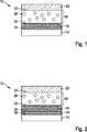
Im dritten Schritt iii) wurde eine Kathode
In Schritt iv) wurde ein der Kathode zugeordneter Stromableiter
Da das galvanische Element
In
Durch das Aufladen des galvanischen Elements
Beim Entladen der Batterie wird dieser Prozess wieder teilweise umgekehrt. Lithium-Ionen werden dabei aus dem Anodenaktivmaterial austreten, durch den Separator
Die Erfindung ist nicht auf die hier beschriebenen Ausführungsbeispiele und die darin hervorgehobenen Aspekte beschränkt. Vielmehr sind innerhalb des durch die Ansprüche angegebenen Bereichs eine Vielzahl von Abwandlungen möglich, die im Rahmen fachmännischen Handelns liegen.The invention is not limited to the embodiments described herein and the aspects highlighted therein. Rather, within the scope given by the claims a variety of modifications are possible, which are within the scope of expert action.
ZITATE ENTHALTEN IN DER BESCHREIBUNG QUOTES INCLUDE IN THE DESCRIPTION
Diese Liste der vom Anmelder aufgeführten Dokumente wurde automatisiert erzeugt und ist ausschließlich zur besseren Information des Lesers aufgenommen. Die Liste ist nicht Bestandteil der deutschen Patent- bzw. Gebrauchsmusteranmeldung. Das DPMA übernimmt keinerlei Haftung für etwaige Fehler oder Auslassungen.This list of the documents listed by the applicant has been generated automatically and is included solely for the better information of the reader. The list is not part of the German patent or utility model application. The DPMA assumes no liability for any errors or omissions.
Zitierte PatentliteraturCited patent literature
- DE 102012205931 A1[0006, 0011]DE 102012205931 A1[0006, 0011]
Claims (10)
Translated fromGermanPriority Applications (5)
| Application Number | Priority Date | Filing Date | Title |
|---|---|---|---|
| DE102014208228.5ADE102014208228A1 (en) | 2014-04-30 | 2014-04-30 | Galvanic element and method for its production |
| JP2016565242AJP6469725B2 (en) | 2014-04-30 | 2015-04-08 | Galvanic element and manufacturing method thereof |
| KR1020167029878AKR20160146745A (en) | 2014-04-30 | 2015-04-08 | Galvanic element and method for the production thereof |
| US15/307,072US20170054139A1 (en) | 2014-04-30 | 2015-04-08 | Galvanic element and method for the production thereof |
| PCT/EP2015/057624WO2015165701A2 (en) | 2014-04-30 | 2015-04-08 | Galvanic element and method for the production thereof |
Applications Claiming Priority (1)
| Application Number | Priority Date | Filing Date | Title |
|---|---|---|---|
| DE102014208228.5ADE102014208228A1 (en) | 2014-04-30 | 2014-04-30 | Galvanic element and method for its production |
Publications (1)
| Publication Number | Publication Date |
|---|---|
| DE102014208228A1true DE102014208228A1 (en) | 2015-11-05 |
Family
ID=52829075
Family Applications (1)
| Application Number | Title | Priority Date | Filing Date |
|---|---|---|---|
| DE102014208228.5AWithdrawnDE102014208228A1 (en) | 2014-04-30 | 2014-04-30 | Galvanic element and method for its production |
Country Status (5)
| Country | Link |
|---|---|
| US (1) | US20170054139A1 (en) |
| JP (1) | JP6469725B2 (en) |
| KR (1) | KR20160146745A (en) |
| DE (1) | DE102014208228A1 (en) |
| WO (1) | WO2015165701A2 (en) |
Cited By (4)
| Publication number | Priority date | Publication date | Assignee | Title |
|---|---|---|---|---|
| DE102015226540A1 (en)* | 2015-12-22 | 2017-06-22 | Robert Bosch Gmbh | Method for producing a battery cell |
| WO2017143274A1 (en)* | 2016-02-19 | 2017-08-24 | American Lithium Energy Corporation | Dual function current collector |
| DE102017217011A1 (en) | 2017-09-26 | 2019-03-28 | Robert Bosch Gmbh | Galvanic element and method for its production |
| GB2594502A (en)* | 2020-04-30 | 2021-11-03 | Ilika Tech Ltd | Connection means for electrochemical cell |
Families Citing this family (18)
| Publication number | Priority date | Publication date | Assignee | Title |
|---|---|---|---|---|
| US9362546B1 (en) | 2013-01-07 | 2016-06-07 | Quantumscape Corporation | Thin film lithium conducting powder material deposition from flux |
| HUE056765T2 (en) | 2013-10-07 | 2022-03-28 | Quantumscape Battery Inc | Bilayers and trilayers comprising lithium-stuffed garnet films and a method for sintering a thin an free standing lithium-stuffed garnet film |
| JP6306935B2 (en)* | 2014-05-09 | 2018-04-04 | 日本碍子株式会社 | Lithium-air battery separator, method for producing the same, and lithium-air battery |
| KR102643560B1 (en) | 2015-04-16 | 2024-03-07 | 퀀텀스케이프 배터리, 인코포레이티드 | Setter plates for solid electrolyte fabrication and methods of using the same to prepare dense solid electrolytes |
| CN107851774A (en) | 2015-07-21 | 2018-03-27 | 昆腾斯科普公司 | Methods and materials for casting and sintering green garnet films |
| US9966630B2 (en) | 2016-01-27 | 2018-05-08 | Quantumscape Corporation | Annealed garnet electrolyte separators |
| JP6786231B2 (en)* | 2016-03-16 | 2020-11-18 | 株式会社東芝 | Laminates for lithium-ion secondary batteries, lithium-ion secondary batteries, battery packs and vehicles |
| EP3455892B1 (en) | 2016-05-13 | 2024-02-07 | QuantumScape Battery, Inc. | Solid electrolyte separator bonding agent |
| US20190214675A1 (en)* | 2016-06-30 | 2019-07-11 | Robert Bosch Gmbh | Method of Forming a Secondary Battery |
| US11158880B2 (en) | 2016-08-05 | 2021-10-26 | Quantumscape Battery, Inc. | Translucent and transparent separators |
| US11916200B2 (en) | 2016-10-21 | 2024-02-27 | Quantumscape Battery, Inc. | Lithium-stuffed garnet electrolytes with a reduced surface defect density and methods of making and using the same |
| US10347937B2 (en) | 2017-06-23 | 2019-07-09 | Quantumscape Corporation | Lithium-stuffed garnet electrolytes with secondary phase inclusions |
| EP4369453A3 (en) | 2017-06-23 | 2024-10-02 | QuantumScape Battery, Inc. | Lithium-stuffed garnet electrolytes with secondary phase inclusions |
| WO2019090360A1 (en) | 2017-11-06 | 2019-05-09 | Quantumscape Corporation | Lithium-stuffed garnet thin films and pellets having an oxyfluorinated and/or fluorinated surface and methods of making and using the thin films and pellets |
| KR20210018419A (en) | 2018-06-06 | 2021-02-17 | 콴텀스케이프 코포레이션 | Solid-state battery |
| WO2020196040A1 (en)* | 2019-03-22 | 2020-10-01 | 富士フイルム株式会社 | All-solid-state lithium ion secondary battery and method for manufacturing same, and negative electrode laminate sheet |
| US20220352501A1 (en)* | 2021-02-25 | 2022-11-03 | Xponential Battery Materials B.V. | Biomass derived porous carbon materials, composites and methods of production |
| WO2022202356A1 (en)* | 2021-03-23 | 2022-09-29 | 田中貴金属工業株式会社 | Positive electrode active material for li ion secondary batteries, method for producing said positive electrode active material, positive electrode for li ion secondary batteries, and li ion secondary battery |
Citations (3)
| Publication number | Priority date | Publication date | Assignee | Title |
|---|---|---|---|---|
| DE69531849T2 (en)* | 1994-05-30 | 2004-08-05 | Canon K.K. | Rechargeable lithium battery |
| DE102012205931A1 (en) | 2012-04-12 | 2013-10-17 | Robert Bosch Gmbh | Electrochemical energy store and method for producing the same |
| EP2586083B1 (en)* | 2010-06-24 | 2014-07-02 | Basf Se | Cathode for lithium ion rechargeable batteries |
Family Cites Families (17)
| Publication number | Priority date | Publication date | Assignee | Title |
|---|---|---|---|---|
| GB2251119B (en)* | 1990-12-20 | 1995-06-07 | Technology Finance Corp | Electrochemical cell |
| ZA94750B (en)* | 1993-09-02 | 1994-09-29 | Technology Finance Corp | Electrochemical cell |
| US6955866B2 (en)* | 1998-09-03 | 2005-10-18 | Polyplus Battery Company | Coated lithium electrodes |
| US6168884B1 (en)* | 1999-04-02 | 2001-01-02 | Lockheed Martin Energy Research Corporation | Battery with an in-situ activation plated lithium anode |
| JP2002203593A (en)* | 2000-10-23 | 2002-07-19 | Sumitomo Electric Ind Ltd | Inorganic solid electrolyte thin film and lithium battery member using the same |
| US6805999B2 (en)* | 2001-11-13 | 2004-10-19 | Midwest Research Institute | Buried anode lithium thin film battery and process for forming the same |
| JP4224583B2 (en)* | 2003-10-06 | 2009-02-18 | 独立行政法人産業技術総合研究所 | Positive electrode material for lithium secondary battery |
| US8313860B2 (en)* | 2004-09-28 | 2012-11-20 | Tadiran Batteries Ltd. | Lithium cell and method of forming same |
| JP4381273B2 (en)* | 2004-10-01 | 2009-12-09 | 株式会社東芝 | Secondary battery and method for manufacturing secondary battery |
| JP4352016B2 (en)* | 2005-03-18 | 2009-10-28 | 株式会社東芝 | Inorganic solid electrolyte battery and method for producing inorganic solid electrolyte battery |
| EP2251922A1 (en)* | 2008-07-25 | 2010-11-17 | Panasonic Corporation | Bipolar cell |
| EP2507858A1 (en)* | 2009-11-30 | 2012-10-10 | OC Oerlikon Balzers AG | Lithium ion battery and method for manufacturing of such battery |
| JP5519356B2 (en)* | 2010-03-23 | 2014-06-11 | ナミックス株式会社 | Lithium ion secondary battery and manufacturing method thereof |
| JP5760638B2 (en)* | 2011-04-21 | 2015-08-12 | 株式会社豊田中央研究所 | Method for producing garnet-type lithium ion conductive oxide |
| JP6144007B2 (en)* | 2011-06-29 | 2017-06-07 | 株式会社豊田中央研究所 | Garnet-type ion conductive oxide and method for producing the same |
| JP5447578B2 (en)* | 2012-04-27 | 2014-03-19 | 株式会社豊田自動織機 | Solid electrolyte and secondary battery |
| US8974946B2 (en)* | 2013-03-15 | 2015-03-10 | Gm Global Technology Operations | Coating for separator or cathode of lithium—sulfur or silicon—sulfur battery |
- 2014
- 2014-04-30DEDE102014208228.5Apatent/DE102014208228A1/ennot_activeWithdrawn
- 2015
- 2015-04-08KRKR1020167029878Apatent/KR20160146745A/ennot_activeWithdrawn
- 2015-04-08WOPCT/EP2015/057624patent/WO2015165701A2/enactiveApplication Filing
- 2015-04-08JPJP2016565242Apatent/JP6469725B2/ennot_activeExpired - Fee Related
- 2015-04-08USUS15/307,072patent/US20170054139A1/ennot_activeAbandoned
Patent Citations (3)
| Publication number | Priority date | Publication date | Assignee | Title |
|---|---|---|---|---|
| DE69531849T2 (en)* | 1994-05-30 | 2004-08-05 | Canon K.K. | Rechargeable lithium battery |
| EP2586083B1 (en)* | 2010-06-24 | 2014-07-02 | Basf Se | Cathode for lithium ion rechargeable batteries |
| DE102012205931A1 (en) | 2012-04-12 | 2013-10-17 | Robert Bosch Gmbh | Electrochemical energy store and method for producing the same |
Cited By (8)
| Publication number | Priority date | Publication date | Assignee | Title |
|---|---|---|---|---|
| DE102015226540A1 (en)* | 2015-12-22 | 2017-06-22 | Robert Bosch Gmbh | Method for producing a battery cell |
| WO2017143274A1 (en)* | 2016-02-19 | 2017-08-24 | American Lithium Energy Corporation | Dual function current collector |
| US10483523B2 (en) | 2016-02-19 | 2019-11-19 | American Lithium Energy Corporation | Dual function current collector |
| US11189819B2 (en) | 2016-02-19 | 2021-11-30 | American Lithium Energy Corporation | Dual function current collector |
| US11575114B2 (en) | 2016-02-19 | 2023-02-07 | American Lithium Energy Corporation | Dual function current collector |
| DE102017217011A1 (en) | 2017-09-26 | 2019-03-28 | Robert Bosch Gmbh | Galvanic element and method for its production |
| GB2594502A (en)* | 2020-04-30 | 2021-11-03 | Ilika Tech Ltd | Connection means for electrochemical cell |
| WO2021219991A1 (en)* | 2020-04-30 | 2021-11-04 | Ilika Technologies Ltd | Connection means for electrochemical cell |
Also Published As
| Publication number | Publication date |
|---|---|
| JP2017517842A (en) | 2017-06-29 |
| JP6469725B2 (en) | 2019-02-13 |
| KR20160146745A (en) | 2016-12-21 |
| WO2015165701A3 (en) | 2016-02-04 |
| US20170054139A1 (en) | 2017-02-23 |
| WO2015165701A2 (en) | 2015-11-05 |
Similar Documents
| Publication | Publication Date | Title |
|---|---|---|
| DE102014208228A1 (en) | Galvanic element and method for its production | |
| DE102014206829A1 (en) | Galvanic element | |
| EP3208869B1 (en) | Rechargeable electrochemical cell | |
| DE102015217749A1 (en) | Coated cathode active material for a battery cell | |
| DE102015112182A1 (en) | Solid lithium secondary battery and manufacturing method therefor | |
| EP2676310B1 (en) | Metal-sulphur battery system | |
| DE102014226390A1 (en) | Composite anode and this comprehensive lithium ion battery and method for producing the composite anode | |
| DE102018218262A1 (en) | Solid electrolyte material with improved chemical stability | |
| DE102014207999A1 (en) | Three-dimensionally structured lithium anode | |
| DE102016215064A1 (en) | Coated solid electrolyte | |
| DE102022107900A1 (en) | COMPOSITE INTERLAYER FOR SOLID STATE BATTERIES BASED ON LITHIUM METAL AND PROCESS FOR THEIR MANUFACTURE | |
| WO2013152906A1 (en) | Electrochemical energy store and method for producing said electrochemical energy store | |
| EP3319099A1 (en) | Battery cell and a battery with electroactive polymers | |
| DE102014211743A1 (en) | Galvanic element and method for its production | |
| DE102014221279A1 (en) | Composite electrode and this comprehensive lithium-ion battery and use of the lithium-ion battery in a motor vehicle | |
| DE102014222332A1 (en) | Layer structure for a galvanic element | |
| DE102016224252A1 (en) | Solid-state cell with concentration gradient | |
| DE102016216549A1 (en) | Solid-state cell with adhesion-promoting layer | |
| DE102013201853A1 (en) | Electrode for a galvanic element and method for producing the electrode | |
| WO2016116317A1 (en) | Electrode coil for a galvanic element, and method for producing same | |
| DE102018219589A1 (en) | Water-based slurry production with cathode active material coated with a solid electrolyte, production of an electrode therefrom and production of a lithium-ion battery cell | |
| DE102014213271A1 (en) | Electrochemical cell | |
| DE102016225925A1 (en) | Battery cell and battery comprising irreversibly lithium-releasing material | |
| DE102016215070A1 (en) | Electrode for solid-state cell with embedded conductivity additive | |
| DE102016216253A1 (en) | Electrode material for a lithium-ion battery |
Legal Events
| Date | Code | Title | Description |
|---|---|---|---|
| R163 | Identified publications notified | ||
| R012 | Request for examination validly filed | ||
| R119 | Application deemed withdrawn, or ip right lapsed, due to non-payment of renewal fee |