DE102014208076A1 - Electrically operated backrest adjuster and vehicle seat with such a backrest adjuster - Google Patents
Electrically operated backrest adjuster and vehicle seat with such a backrest adjusterDownload PDFInfo
- Publication number
- DE102014208076A1 DE102014208076A1DE201410208076DE102014208076ADE102014208076A1DE 102014208076 A1DE102014208076 A1DE 102014208076A1DE 201410208076DE201410208076DE 201410208076DE 102014208076 ADE102014208076 ADE 102014208076ADE 102014208076 A1DE102014208076 A1DE 102014208076A1
- Authority
- DE
- Germany
- Prior art keywords
- fitting
- electrically operated
- seat
- backrest adjuster
- transmission rod
- Prior art date
- Legal status (The legal status is an assumption and is not a legal conclusion. Google has not performed a legal analysis and makes no representation as to the accuracy of the status listed.)
- Ceased
Links
- 230000005540biological transmissionEffects0.000claimsabstractdescription36
- 238000000034methodMethods0.000claimsdescription5
- 238000009420retrofittingMethods0.000description5
- 238000011161developmentMethods0.000description2
- 230000018109developmental processEffects0.000description2
- 238000009434installationMethods0.000description2
- 230000001419dependent effectEffects0.000description1
Images


Classifications
- B—PERFORMING OPERATIONS; TRANSPORTING
- B60—VEHICLES IN GENERAL
- B60N—SEATS SPECIALLY ADAPTED FOR VEHICLES; VEHICLE PASSENGER ACCOMMODATION NOT OTHERWISE PROVIDED FOR
- B60N2/00—Seats specially adapted for vehicles; Arrangement or mounting of seats in vehicles
- B60N2/02—Seats specially adapted for vehicles; Arrangement or mounting of seats in vehicles the seat or part thereof being movable, e.g. adjustable
- B60N2/0224—Non-manual adjustments, e.g. with electrical operation
- B60N2/02246—Electric motors therefor
- B60N2/02258—Electric motors therefor characterised by the mounting of the electric motor for adjusting the seat
- B—PERFORMING OPERATIONS; TRANSPORTING
- B60—VEHICLES IN GENERAL
- B60N—SEATS SPECIALLY ADAPTED FOR VEHICLES; VEHICLE PASSENGER ACCOMMODATION NOT OTHERWISE PROVIDED FOR
- B60N2/00—Seats specially adapted for vehicles; Arrangement or mounting of seats in vehicles
- B60N2/02—Seats specially adapted for vehicles; Arrangement or mounting of seats in vehicles the seat or part thereof being movable, e.g. adjustable
- B60N2/22—Seats specially adapted for vehicles; Arrangement or mounting of seats in vehicles the seat or part thereof being movable, e.g. adjustable the back-rest being adjustable
- B60N2/225—Seats specially adapted for vehicles; Arrangement or mounting of seats in vehicles the seat or part thereof being movable, e.g. adjustable the back-rest being adjustable by cycloidal or planetary mechanisms
- B—PERFORMING OPERATIONS; TRANSPORTING
- B60—VEHICLES IN GENERAL
- B60N—SEATS SPECIALLY ADAPTED FOR VEHICLES; VEHICLE PASSENGER ACCOMMODATION NOT OTHERWISE PROVIDED FOR
- B60N2/00—Seats specially adapted for vehicles; Arrangement or mounting of seats in vehicles
- B60N2/02—Seats specially adapted for vehicles; Arrangement or mounting of seats in vehicles the seat or part thereof being movable, e.g. adjustable
- B60N2/0224—Non-manual adjustments, e.g. with electrical operation
- B60N2/02246—Electric motors therefor
- B60N2/02253—Electric motors therefor characterised by the transmission between the electric motor and the seat or seat parts
- B—PERFORMING OPERATIONS; TRANSPORTING
- B60—VEHICLES IN GENERAL
- B60N—SEATS SPECIALLY ADAPTED FOR VEHICLES; VEHICLE PASSENGER ACCOMMODATION NOT OTHERWISE PROVIDED FOR
- B60N2/00—Seats specially adapted for vehicles; Arrangement or mounting of seats in vehicles
- B60N2/02—Seats specially adapted for vehicles; Arrangement or mounting of seats in vehicles the seat or part thereof being movable, e.g. adjustable
- B60N2/20—Seats specially adapted for vehicles; Arrangement or mounting of seats in vehicles the seat or part thereof being movable, e.g. adjustable the back-rest being tiltable, e.g. to permit easy access
- B—PERFORMING OPERATIONS; TRANSPORTING
- B60—VEHICLES IN GENERAL
- B60N—SEATS SPECIALLY ADAPTED FOR VEHICLES; VEHICLE PASSENGER ACCOMMODATION NOT OTHERWISE PROVIDED FOR
- B60N2/00—Seats specially adapted for vehicles; Arrangement or mounting of seats in vehicles
- B60N2/02—Seats specially adapted for vehicles; Arrangement or mounting of seats in vehicles the seat or part thereof being movable, e.g. adjustable
- B60N2/22—Seats specially adapted for vehicles; Arrangement or mounting of seats in vehicles the seat or part thereof being movable, e.g. adjustable the back-rest being adjustable
- B60N2/225—Seats specially adapted for vehicles; Arrangement or mounting of seats in vehicles the seat or part thereof being movable, e.g. adjustable the back-rest being adjustable by cycloidal or planetary mechanisms
- B60N2/2254—Seats specially adapted for vehicles; Arrangement or mounting of seats in vehicles the seat or part thereof being movable, e.g. adjustable the back-rest being adjustable by cycloidal or planetary mechanisms provided with braking systems
- B60N2/2258—Seats specially adapted for vehicles; Arrangement or mounting of seats in vehicles the seat or part thereof being movable, e.g. adjustable the back-rest being adjustable by cycloidal or planetary mechanisms provided with braking systems with ratchets
Landscapes
- Engineering & Computer Science (AREA)
- Aviation & Aerospace Engineering (AREA)
- Transportation (AREA)
- Mechanical Engineering (AREA)
- Chairs For Special Purposes, Such As Reclining Chairs (AREA)
- Seats For Vehicles (AREA)
Abstract
Translated fromGermanDescription
Translated fromGermanDie Erfindung betrifft einen Lehnenversteller zur elektrisch betriebenen Verstellung einer Sitzlehne eines Fahrzeugsitzes und einen Fahrzeugsitz mit einem solchen elektrisch betriebenen Lehnenversteller sowie ein Montageverfahren eines solchen Lehnenverstellers.The invention relates to a Lehnenversteller for electrically operated adjustment of a seat back of a vehicle seat and a vehicle seat with such an electrically operated Lehnenversteller and an assembly method of such Lehnenverstellers.
Im Stand der Technik sind verschiedene Lehnenversteller mit Beschlägen zur manuellen oder elektrisch betriebenen Verstellung einer Sitzlehne eines Fahrzeugsitzes mit oder ohne Easy-Entry-Systeme bekannt, welche verschiedene Komfort- oder Gebrauchsstellungen der Sitzlehne bzw. einen erleichterten Einstieg in eine zweite Sitzreihe eines Fahrzeuges ermöglichen. Der Beschlag ist durch einen Entriegelungshebel, welcher üblicherweise an einer Rückenlehne des Fahrzeugsitzes angeordnet ist, betätigbar, wodurch die Rückenlehne des Fahrzeugsitzes in eine Komfortstellung bzw. aus einem Einstiegsbereich schwenkt. Ist der Fahrzeugsitz auf Schienen angeordnet, kann der Fahrzeugsitz bei Betätigung des Entriegelungshebels zusätzlich in Fahrtrichtung aus dem Einstiegsbereich heraus verschiebbar sein.Various Lehnenversteller with fittings for manual or electrically operated adjustment of a seat back of a vehicle seat with or without easy-entry systems are known in the art, which allow different comfort or use positions of the seat back and a facilitated entry into a second row of seats of a vehicle. The fitting is actuated by a release lever, which is usually arranged on a backrest of the vehicle seat, whereby the backrest of the vehicle seat pivots in a comfort position or from an access area. If the vehicle seat is arranged on rails, the vehicle seat can additionally be displaceable out of the access area in the direction of travel when the unlocking lever is actuated.
Aufgabe der vorliegenden Erfindung ist es, einen verbesserten Lehnenversteller mit einem Beschlag mit einer elektrisch betriebenen Verstellung einer Sitzlehne und einen Fahrzeugsitz mit einem verbesserten Lehnenversteller anzugeben. Des Weiteren ist es Aufgabe der Erfindung, ein Verfahren zur Montage eines solchen Lehnenverstellers anzugeben.The object of the present invention is to specify an improved backrest adjuster with a fitting with an electrically operated adjustment of a seat back and a vehicle seat with an improved backrest adjuster. Furthermore, it is the object of the invention to specify a method for assembling such a backrest adjuster.
Hinsichtlich des Lehnenverstellers wird die Aufgabe durch die im Patentanspruch 1 angegebenen Merkmale gelöst. Hinsichtlich des Fahrzeugsitzes wird die Aufgabe erfindungsgemäß durch die im Patentanspruch 9 angegebenen Merkmale gelöst. Hinsichtlich des Verfahrens zur Montage eines solchen Lehnenverstellers wird die Aufgabe durch die im Patentanspruch 10 angegebenen Merkmale gelöst.With regard to the Lehnenverstellers the object is achieved by the features specified in
Vorteilhafte Weiterbildungen der Erfindung sind Gegenstand der Unteransprüche.Advantageous developments of the invention are the subject of the dependent claims.
Der erfindungsgemäße elektrisch betriebene Lehnenversteller für einen Fahrzeugsitz mit einem Sitzteil und einer relativ zum Sitzteil verstellbaren Sitzlehne, umfasst zwei Beschlagseiten,
- – von denen jede ein sitzlehnenfestes Beschlagoberteil und ein an einem Unterbau befestigtes oder sitzteilfestes Beschlagunterteil umfasst, und
- – von denen zumindest eine einen Beschlag zur Neigungsverstellung der Sitzlehne umfasst, wobei der Beschlag zwischen dem Beschlagoberteil und dem Beschlagunterteil angeordnet ist und die Beschlagseiten mittels einer Übertragungsstange miteinander gekoppelt sind, wobei auf einer der Beschlagseiten eine elektrische Antriebseinheit vorgesehen ist, die außen am zugehörigen Beschlagunterteil angeordnet ist und mit der Übertragungsstange zum Antrieb dieser gekoppelt ist.
- - Each of which comprises a seat back fixed fitting upper part and a fixed to a base or seat part fixed lower fitting part, and
- - Of which at least one includes a fitting for tilt adjustment of the seat back, wherein the fitting between the fitting upper part and the fitting base is arranged and the fitting sides are coupled together by means of a transmission rod, wherein on one of the fitting sides an electric drive unit is provided, the outside of the associated fitting base is arranged and coupled to the transmission rod to drive this.
Die Erfindung ermöglicht einen einfach aufgebauten elektrisch betriebenen Lehnenversteller, welcher insbesondere eine geringe Anzahl von Teilen aufweist, wobei eine Vielzahl dieser Teile Gleichteile sind, welche unabhängig vom zugrunde liegenden Fahrzeugsitztyp bei verschiedenartigen Fahrzeugsitzen verwendet werden können. Hierdurch ist ein besonders kostengünstiger elektrisch betriebener Lehnenversteller ermöglicht. Darüber hinaus kann der elektrisch betriebene Lehnenversteller als eine vorgefertigte Montageeinheit ausgebildet sein, die zur Nachrüstung oder Montage an bereits vorhandenen Fahrzeugsitzen geeignet ist.The invention enables a simply constructed electrically operated recliner, which in particular has a small number of parts, wherein a plurality of these parts are identical parts, which can be used regardless of the underlying vehicle seat type in various types of vehicle seats. As a result, a particularly cost-effective electrically operated backrest adjuster is made possible. In addition, the electrically operated Lehnenversteller be designed as a prefabricated mounting unit, which is suitable for retrofitting or mounting on existing vehicle seats.
Eine Ausgestaltung der Erfindung sieht vor, dass der Beschlag als Dreh- und/oder Rastbeschlag ausgebildet ist. Damit sind verschiedene Komfort- oder Gebrauchsstellungen der Sitzlehne bzw. ein erleichterter Einstieg in einen Fondbereich eines Fahrzeuges möglich.An embodiment of the invention provides that the fitting is designed as a rotary and / or latching fitting. Thus, various comfort or use positions of the seat back and a facilitated entry into a rear area of a vehicle are possible.
Eine einfache Ausführungsform sieht vor, dass das Beschlagunterteil der antriebsseitigen Beschlagseite derart ausgebildet ist, dass dieses das Gehäuse für die elektrische Antriebseinheit bildet. Alternativ kann ein zusätzliches Gehäuseteil, insbesondere ein Gehäuseboden oder -deckel für die elektrische Antriebseinheit am Beschlagunterteil angeordnet sein.A simple embodiment provides that the lower fitting part of the drive side fitting side is formed such that this forms the housing for the electric drive unit. Alternatively, an additional housing part, in particular a housing bottom or cover for the electric drive unit may be arranged on the fitting lower part.
In einer Weiterbildung ist am Beschlagunterteil der antriebsseitigen Beschlagseite ein Aktuator/Aktor, insbesondere ein Stellelement, insbesondere ein Antriebssteller, angeordnet, der mit einer Betätigungseinheit, insbesondere einem Hebelelement, zur Entriegelung oder Verriegelung des Beschlags im Wirkzusammenhang steht.In a further development, an actuator / actuator, in particular an actuating element, in particular a drive plate, is arranged on the fitting lower part of the drive-side fitting side, which is in operative connection with an actuating unit, in particular a lever element, for unlocking or locking the fitting.
Darüber hinaus ist am Beschlagunterteil der antriebsseitigen Beschlagseite ein Schaltelement, insbesondere ein Mikroschalter oder ein Stellungsgeber, angeordnet, der mit dem Hebelelement zur Bestimmung dessen Position im Wirkzusammenhang steht.In addition, a switching element, in particular a microswitch or a position transmitter, is arranged on the fitting lower part of the drive-side fitting side, which is in operative connection with the lever element for determining its position.
In einer möglichen Ausführungsform umfasst die elektrische Antriebseinheit einen Motor mit einer Antriebswelle und einem auf der Antriebswelle angeordneten Ritzel, insbesondere einem Antriebsrad, welches in Eingriff mit einem Anschlagselement, insbesondere einem Abtriebsrad, steht, das drehfest mit dem Beschlagoberteil und der Übertragungsstange verbunden ist. Dabei kann es sich bei dem Ritzel und dem Anschlagselement um eine Zahnradpaarung oder ein anderes Radgetriebe, wie ein Planetengetriebe handeln.In one possible embodiment, the electric drive unit comprises a motor having a drive shaft and a pinion arranged on the drive shaft, in particular a drive wheel, which is in engagement with a stop element, in particular a driven wheel, which is non-rotatably connected to the fitting upper part and the transmission rod. It may be at the pinion and the stop element to a Gear pairing or another wheel gear, act as a planetary gear.
Ferner sieht eine Ausführungsform vor, dass das jeweilige Beschlagunterteil derart ausgebildet ist, das dieses an einer bodenfesten Komponente des Sitzteils und/oder an einem Unterbau form-, kraft- und/oder stoffschlüssig befestigt ist. Dazu korrespondierend ist das jeweilige Beschlagoberteil derart ausgebildet, dass dieses an einer Rahmenstruktur der Sitzlehne form-, kraft- und/oder stoffschlüssig befestigt ist. Das Beschlagoberteil und das Beschlagunterteil sind bei entriegeltem Beschlag relativ zueinander bewegbar, insbesondere drehbar, wozu der Beschlag als eine Getriebeverbindung, insbesondere als ein Zahnradgetriebe und/oder ein Planetenradgetriebe ausgebildet ist.Furthermore, an embodiment provides that the respective lower fitting part is designed in such a way that it is fixed to a base-fixed component of the seat part and / or to a substructure in a form-fitting, force-fitting and / or material-locking manner. Correspondingly, the respective fitting upper part is designed in such a way that it is fastened to a frame structure of the seat back in a form-fitting, force-fitting and / or material-locking manner. When the fitting is unlocked, the fitting upper part and the fitting lower part are movable relative to each other, in particular rotatable, for which purpose the fitting is designed as a gear connection, in particular as a gear transmission and / or a planetary gear.
Eine bevorzugte Ausführungsform sieht vor, dass der elektrisch betriebene Lehnenversteller als eine vorgefertigte Montageeinheit ausgebildet ist, die zumindest die folgenden Komponenten umfasst: zwei Beschlagseiten, von denen jede ein Beschlagoberteil und ein Beschlagunterteil umfasst, und von denen zumindest eine einen Beschlag zur Neigungsverstellung der Sitzlehne umfasst, wobei der Beschlag zwischen dem Beschlagoberteil und dem Beschlagunterteil angeordnet ist und die Beschlagseiten mittels einer Übertragungsstange miteinander gekoppelt sind, und wobei auf einer der Beschlagseiten eine elektrische Antriebseinheit vorgesehen ist, die außen am zugehörigen Beschlagunterteil angeordnet ist und mit der Übertragungsstange zum Antrieb dieser gekoppelt ist.A preferred embodiment provides that the electrically operated Lehnenversteller is designed as a prefabricated mounting unit comprising at least the following components: two fitting sides, each of which comprises a fitting upper part and a fitting lower part, and at least one of which includes a fitting for tilt adjustment of the seat back wherein the fitting is arranged between the fitting upper part and the fitting lower part and the fitting sides are coupled to one another by means of a transmission rod, and wherein on one of the fitting sides an electric drive unit is provided, which is arranged on the outside of the associated fitting lower part and is coupled to the transmission rod for driving it ,
Ein erfindungsgemäßer Fahrzeugsitz mit einer neigungseinstellbaren und frei schwenkbaren Sitzlehne weist den zuvor beschriebenen elektrisch betriebenen Lehnenversteller auf, der insbesondere als eine vorgefertigte Montageeinheit ausgebildet sein kann, die zur Nachrüstung oder Montage an bereits vorhandenen Fahrzeugsitzen geeignet ist.An inventive vehicle seat with a tilt-adjustable and freely pivoting seat back has the electrically operated backrest adjuster described above, which can be designed in particular as a prefabricated mounting unit, which is suitable for retrofitting or mounting on existing vehicle seats.
Das erfindungsgemäße Verfahren zur Montage eines elektrisch betriebenen Lehnenverstellers umfasst zumindest folgende Schritte:
- – Zusammenbau der zwei Beschlagoberteile und der diese verbindende Übertragungsstange,
- – Aufsetzen und Befestigen des zumindest einen Beschlages an einer der Beschlagseiten auf einem aus dem betreffenden Beschlagoberteil hinausragenden Ende der Übertragungsstange,
- – Aufsetzen und Anordnung der Beschlagunterteile auf die aus den Beschlägen hinausragenden Enden der Übertragungsstange,
- – Aufsetzen und Befestigen einer Betätigungseinheit außen auf einer der Beschlagseiten an einem Beschlagunterteil,
- – Montieren einer Antriebswelle mit einem Ritzel an diesem Beschlagunterteil, an welchem die Betätigungseinheit befestigt ist,
- – Montieren und Befestigen einer elektrischen Antriebseinheit außen an diesem betreffenden Beschlagunterteil, insbesondere Montieren und Befestigen der zugehörigen Komponenten, wie eines Motors, eines Aktuators, eines Schaltelements.
- - assembly of the two upper fitting parts and the transmission rod connecting them,
- Placing and fastening the at least one fitting on one of the fitting sides on an end of the transmission rod projecting from the relevant fitting upper part,
- Placing and arranging the lower fitting parts on the ends of the transmission rod projecting from the fittings,
- Placing and fastening an actuating unit on the outside on one of the fitting sides on a fitting lower part,
- Mounting a drive shaft with a pinion on this fitting lower part, to which the actuating unit is fastened,
- Mounting and fixing an electric drive unit on the outside of this relevant fitting base, in particular mounting and fixing the associated components, such as a motor, an actuator, a switching element.
Die Aufgabe wird des Weiteren erfindungsgemäß durch einen Lehnenversteller mit einem Beschlag zur elektrisch betriebenen Verstellung einer Sitzlehne gelöst, wobei der Beschlag aus einem Beschlagoberteil, welches an der Rückenlehne angeordnet ist, und einem an einem Unterbau befestigten Beschlagunterteil gebildet ist. Dabei kann an jeweils einer Seite eines Fahrzeugsitzes ein solcher Beschlag angeordnet sein. Dabei ist der Beschlag zur Positionierung einer Sitzlehne eines Fahrzeugsitzes in eine Easy-Entry-Position, einer integrierten Komfortverriegelung zur Positionierung der Sitzlehne in mindestens eine Komfort- oder Sitzposition und einer erweiterten Komfortfunktion zur Positionierung der Sitzlehne über die Easy-Entry-Position hinaus in eine Ladebodenposition vorgesehen. Der erfindungsgemäße Beschlag umfasst wenigstens ein Beschlagteil und einen Mitnehmer, der mit einem Komforthebel in Eingriff steht, wobei ein Schwenkbereich der Sitzlehne in der Easy-Entry-Position mittels einer in das zumindest eine Beschlagteil eingreifenden Easy-Entry-Klinke begrenzt ist, wobei der Mitnehmer zur Entriegelung des Beschlags mit einem Entriegelungshebel koppelbar ist und zur Positionierung der Sitzlehne aus der Easy-Entry-Position hinaus in die Ladebodenposition von dem Entriegelungshebel entkoppelbar ist, wobei im entkoppelten Zustand vom Mitnehmer und Entriegelungshebel dieser bei dessen Betätigung die Easy-Entry-Klinke mitnimmt.The object is further achieved according to the invention by a Lehnenversteller with a fitting for the electrically operated adjustment of a seat back, wherein the fitting of a fitting upper part, which is arranged on the backrest, and a base attached to a fitting lower part is formed. It can be arranged on each side of a vehicle seat, such a fitting. Here, the fitting for positioning a seat back of a vehicle seat in an easy-entry position, an integrated comfort lock for positioning the seat back in at least one comfort or seating position and an advanced comfort function for positioning the seat back on the easy-entry position also in one Loading floor position provided. The fitting according to the invention comprises at least one fitting part and a driver, which is in engagement with a comfort lever, wherein a pivoting range of the seat back in the easy-entry position is limited by means of an engaging in the at least one fitting Easy-entry pawl, wherein the driver for unlocking the fitting with a release lever can be coupled and for the positioning of the seat back from the easy-entry position out into the loading floor position of the unlocking lever can be decoupled, in the decoupled state of the driver and release lever this entrains the easy-entry pawl when actuated ,
Ausführungsbeispiele der Erfindung werden nachfolgend anhand von schematischen Figuren näher erläutert. Dabei zeigen:Embodiments of the invention are explained in more detail with reference to schematic figures. Showing:
Einander entsprechende Teile sind in allen Figuren mit den gleichen Bezugszeichen versehen.Corresponding parts are provided in all figures with the same reference numerals.
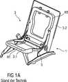
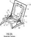
Die
Der Fahrzeugsitz
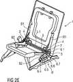
Der erfindungsgemäße elektrisch betriebene Lehnenversteller
Zur elektrisch betriebenen Neigungsverstellung der Sitzlehne
Der elektrisch betriebene Lehnenversteller
Auf einer der Beschlagseiten ist außen am betreffenden Beschlagunterteil B2 die elektrische Antriebseinheit
Die elektrische Antriebseinheit
Die fertig montierte und vorgefertigte Montageeinheit M des elektrisch betriebenen Lehnenverstellers
Wie in den Teilfigur
Mittels einer solchen vorgefertigten Montageeinheit M des elektrisch betriebenen Lehnenverstellers
Teilfigur
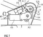
Zur elektrischen Verstellung der Sitzlehne
Die elektrische Antriebseinheit
Der Beschlag
Zur Nachrüstung oder Montage der elektrischen Antriebseinheit
Anschließend wird, wie in
Anstelle einer Montage der einzelnen Komponenten der elektrischen Antriebseinheit
Hierzu werden beispielsweise zunächst die zwei Beschlagoberteile B1 und die diese verbindende Übertragungsstange
Dazu umfasst die elektrische Antriebseinheit
Im Gehäuse und somit am inneren Gehäuseteil
Die Betätigungseinheit
Zum Öffnen des Beschlags
Der Aktuator
Das beispielsweise als ein Mikroschalter oder Stellungsgeber ausgebildete Schaltelement
Das Ritzel
Das Anschlagselement
Das Anschlagselement
Der Beschlag
Das erste Beschlagteil
Zur Aufnahme der axial wirkenden Kräfte und zum Zusammenhalt der Beschlagteile
Im Zentrum des Beschlags
Der von der Federanordnung
Eine Steuerscheibe
Optional weist der Beschlag
Die Komponenten des Beschlags
BezugszeichenlisteLIST OF REFERENCE NUMBERS
- 1, 1‘‘1, 1 ''
- elektrisch betriebener LehnenverstellerElectrically operated backrest adjuster
- 1‘1'
- manuell betätigbarer Lehnenverstellermanually operated backrest adjuster
- 22
- Beschlag fitting
- 2‘2 '
- DrehbeschlagPivoting fitting
- 2.12.1
- erstes Beschlagteilfirst fitting part
- 2.22.2
- zweites Beschlagteilsecond fitting part
- 2.2.12.2.1
- Führungssegmentguide segment
- 2.32.3
- Umklammerungsringclasping
- 2.42.4
- Riegelbars
- 2.52.5
- Mitnehmertakeaway
- 2.62.6
- Exzentereccentric
- 2.72.7
- Federanordnungspring assembly
- 2.82.8
- Steuerscheibecontrol disc
- 2.92.9
- Freischwenk-SteuerelementFree-pivoting control
- 2.102.10
- Sicherungselementfuse element
- 33
- Fahrzeugsitz vehicle seat
- 3.13.1
- Sitzteilseat part
- 3.23.2
- Sitzlehneseatback
- 44
- Halteelement retaining element
- 55
- Übertragungsstange transmission rod
- 5.15.1
- Übertragungsrohrtransfer tube
- 6, 6‘6, 6 '
- elektrische Antriebseinheitelectric drive unit
- 6.16.1
- Betätigungseinheitoperating unit
- 6.1.16.1.1
- Hebelelementlever member
- 6.26.2
- Antriebswelledrive shaft
- 6.36.3
- Ritzelpinion
- 6.46.4
- Gehäuseteil (inneres)Housing part (inner)
- 6.56.5
- Motorengine
- 6.66.6
- Aktuatoractuator
- 6.76.7
- Schaltelementswitching element
- 6.86.8
- Gehäuseteil (äußeres)Housing part (outer)
- 77
- Drehlager pivot bearing
- 88th
- Anschlagelement stop element
- B1B1
- BeschlagoberteilUpper member
- B2B2
- BeschlagunterteilFitting part
- b1, b2b1, b2
- Breite width
- d1 bis d3d1 to d3
- Durchmesser diameter
- M,M’M, M '
- Montageeinheitassembly unit
- RR
- Richtung direction
- RTRT
- Rahmenteilframe part
- S1S1
- erste Stellungfirst position
- S2S2
- zweite Stellungsecond position
Claims (8)
Translated fromGermanPriority Applications (6)
| Application Number | Priority Date | Filing Date | Title |
|---|---|---|---|
| DE201410208076DE102014208076A1 (en) | 2013-10-23 | 2014-04-29 | Electrically operated backrest adjuster and vehicle seat with such a backrest adjuster |
| EP14787148.7AEP3060425B1 (en) | 2013-10-23 | 2014-10-17 | Electrically operated backrest adjuster and vehicle seat with such a backrest adjuster |
| US15/031,441US10011190B2 (en) | 2013-10-23 | 2014-10-17 | Electrically operated backrest adjuster and vehicle seat with such a backrest adjuster |
| CN201480058138.5ACN105658471B (en) | 2013-10-23 | 2014-10-17 | Electrically operated backrest adjuster and vehicle seat with such a backrest adjuster |
| PCT/EP2014/072340WO2015059053A1 (en) | 2013-10-23 | 2014-10-17 | Electrically operated backrest adjuster and vehicle seat with such a backrest adjuster |
| JP2016525586AJP6248192B2 (en) | 2013-10-23 | 2014-10-17 | Electric backrest adjustment device and vehicle seat having such a backrest adjustment device |
Applications Claiming Priority (3)
| Application Number | Priority Date | Filing Date | Title |
|---|---|---|---|
| DE102013221568 | 2013-10-23 | ||
| DE102013221568.1 | 2013-10-23 | ||
| DE201410208076DE102014208076A1 (en) | 2013-10-23 | 2014-04-29 | Electrically operated backrest adjuster and vehicle seat with such a backrest adjuster |
Publications (1)
| Publication Number | Publication Date |
|---|---|
| DE102014208076A1true DE102014208076A1 (en) | 2015-05-07 |
Family
ID=52829907
Family Applications (1)
| Application Number | Title | Priority Date | Filing Date |
|---|---|---|---|
| DE201410208076CeasedDE102014208076A1 (en) | 2013-10-23 | 2014-04-29 | Electrically operated backrest adjuster and vehicle seat with such a backrest adjuster |
Country Status (6)
| Country | Link |
|---|---|
| US (1) | US10011190B2 (en) |
| EP (1) | EP3060425B1 (en) |
| JP (1) | JP6248192B2 (en) |
| CN (1) | CN105658471B (en) |
| DE (1) | DE102014208076A1 (en) |
| WO (1) | WO2015059053A1 (en) |
Families Citing this family (17)
| Publication number | Priority date | Publication date | Assignee | Title |
|---|---|---|---|---|
| DE102014208076A1 (en)* | 2013-10-23 | 2015-05-07 | Johnson Controls Components Gmbh & Co. Kg | Electrically operated backrest adjuster and vehicle seat with such a backrest adjuster |
| US9902295B2 (en)* | 2015-08-25 | 2018-02-27 | Fisher & Company, Incorporated | Single-stage gear reduction output mechanism with a locking fork providing anti-back drive capability for automotive seat adjuster drives |
| US10843591B2 (en) | 2016-01-19 | 2020-11-24 | Fisher & Company, Incorporated | Gear assembly for a seat adjuster |
| JP6690408B2 (en)* | 2016-05-27 | 2020-04-28 | トヨタ紡織株式会社 | Seat adjuster |
| US10765575B2 (en) | 2016-06-29 | 2020-09-08 | Stryker Corporation | Patient support systems with rotary actuators comprising rotation limiting devices |
| US10813807B2 (en)* | 2016-06-29 | 2020-10-27 | Stryker Corporation | Patient support systems with hollow rotary actuators |
| US10864128B2 (en) | 2016-06-29 | 2020-12-15 | Stryker Corporation | Patient support systems with rotary actuators having cycloidal drives |
| US11766956B2 (en) | 2016-09-08 | 2023-09-26 | Fisher & Company, Incorporated | Open architecture power length adjuster assembly for a vehicle seat and method of manufacturing the same |
| US10953772B2 (en) | 2016-09-08 | 2021-03-23 | Fisher & Company, Incorporated | Open architecture power length adjuster assembly for a vehicle seat and method of manufacturing the same |
| US11273506B2 (en) | 2016-09-08 | 2022-03-15 | Fisher & Company, Incorporated | Open architecture power length adjuster assembly for a vehicle seat and method of manufacturing the same |
| EP3385165A1 (en)* | 2017-04-03 | 2018-10-10 | Adient US LLC | A seat for a vehicle |
| KR20210057805A (en)* | 2018-09-17 | 2021-05-21 | 에르고모션, 아이엔씨. | Lightweight self-contained articulating assembly for mounting bed frames |
| CN113272172B (en) | 2019-01-09 | 2023-06-27 | 费舍尔和同伴有限公司 | Power seat track assembly |
| US11760233B2 (en) | 2019-02-20 | 2023-09-19 | Fisher & Company, Incorporated | Ultra-compact power length adjuster with anti-back drive capability and pinion-rack output for a vehicle seat |
| US11529892B2 (en) | 2020-05-01 | 2022-12-20 | Fisher & Company, Incorporated | Gearbox for vehicle seat adjustment mechanism |
| US11485255B2 (en) | 2020-05-01 | 2022-11-01 | Fisher & Company, Incorporated | Gearbox for vehicle seat adjustment mechanism |
| CN116572803A (en)* | 2023-04-28 | 2023-08-11 | 上海吉祥智驱新能源汽车有限公司 | Vehicle rear seat framework structure, vehicle rear row and vehicle |
Family Cites Families (127)
| Publication number | Priority date | Publication date | Assignee | Title |
|---|---|---|---|---|
| US4457557A (en)* | 1981-12-30 | 1984-07-03 | Toshiaki Une | Reclining device for use in a vehicle |
| US4704912A (en)* | 1986-05-13 | 1987-11-10 | Honeywell Inc. | Sliding crank actuator |
| JPH03279033A (en)* | 1990-03-28 | 1991-12-10 | Tachi S Co Ltd | Control method for motor of power seat and device therefor |
| JP3143960B2 (en)* | 1991-07-09 | 2001-03-07 | アイシン精機株式会社 | Seat reclining device |
| DE4303819C2 (en)* | 1992-04-07 | 1996-08-08 | Keiper Recaro Gmbh Co | Locking and locking fitting for seats, in particular motor vehicle seats |
| US5547254A (en)* | 1992-09-30 | 1996-08-20 | Aisin Seiki Kabushiki Kaisha | Pawl and ratchet type seat tilt control apparatus |
| US5433507A (en)* | 1993-10-06 | 1995-07-18 | Chang; Chung L. | Seatback recliner mechanism |
| US5435624A (en)* | 1993-10-12 | 1995-07-25 | Ford Motor Company | Powered vehicle seat |
| DE4436101C5 (en)* | 1993-11-30 | 2008-12-11 | Keiper Gmbh & Co.Kg | Lehneneinstellbeschlag for seats with adjustable backrest, in particular motor vehicle seats |
| DE4340696C1 (en)* | 1993-11-30 | 1995-06-29 | Keiper Recaro Gmbh Co | Back rest adjusting device for vehicle seats |
| JP3477774B2 (en)* | 1993-12-22 | 2003-12-10 | アイシン精機株式会社 | Seat reclining device |
| JP2858450B2 (en)* | 1993-12-27 | 1999-02-17 | トヨタ車体株式会社 | Reclining mechanism for vehicle seat |
| US5634380A (en)* | 1994-03-31 | 1997-06-03 | Keiper Recaro Gmbh & Co. | Articulated fitting for seats with adjustable backrest in particular for motor vehicle seats |
| FR2722150B1 (en)* | 1994-07-05 | 1996-09-27 | Cesa | ARTICULATION WITH SEAT ADJUSTMENT POSITION |
| US5516198A (en)* | 1994-09-28 | 1996-05-14 | Tachi-S Co., Ltd. | Reclining device for vehicle seat |
| US5590932A (en)* | 1994-11-07 | 1997-01-07 | Fisher Dynamics Corporation | Anti-chuck seat recliner |
| DE19500914A1 (en)* | 1995-01-13 | 1996-07-18 | Hammerstein Gmbh C Rob | Hinge joint for vehicle seat adjustable backrest with cam-locked gears |
| US5567013A (en)* | 1995-02-17 | 1996-10-22 | Chang; Chung L. | Seat support and slide mechanism |
| US5718481A (en)* | 1995-03-28 | 1998-02-17 | Fisher Dynamics Corporation | Seat recliner mechanism |
| JPH09193696A (en)* | 1996-01-17 | 1997-07-29 | Asmo Co Ltd | Power seat device |
| US5664836A (en)* | 1996-03-29 | 1997-09-09 | Tachi-S Co., Ltd. | Reclining device for vehicle seat |
| US5685610A (en)* | 1996-04-08 | 1997-11-11 | Tachi-S Co., Ltd. | Reclining device for seat |
| JP3661282B2 (en)* | 1996-07-03 | 2005-06-15 | アイシン精機株式会社 | Seat adjustment device |
| GB9614787D0 (en)* | 1996-07-13 | 1996-09-04 | Johnson Controls Adwest | Seat reclining mechanism |
| JP3313590B2 (en)* | 1996-09-30 | 2002-08-12 | 富士機工株式会社 | Seat reclining device |
| US6142569A (en)* | 1997-02-13 | 2000-11-07 | Nhk Spring Co., Ltd, | Reclining device |
| US5813725A (en)* | 1997-09-04 | 1998-09-29 | Fisher Dynamics Corporation | Rotary gear lock seat recliner |
| DE29802055U1 (en)* | 1998-02-10 | 1999-06-10 | Schwarzbich, Jörg, 33615 Bielefeld | Seat adjuster |
| DE29809418U1 (en)* | 1998-05-26 | 1999-09-30 | Schwarzbich, Jörg, 33615 Bielefeld | Adjustment mechanism |
| US6209955B1 (en)* | 1998-10-21 | 2001-04-03 | Johnson Controls Technology Company | Vehicle seat with a yielding recliner stop |
| US6109690A (en)* | 1998-12-18 | 2000-08-29 | Johnson Controls Technology Company | Pivoting seat back |
| JP3540952B2 (en)* | 1998-12-21 | 2004-07-07 | 富士機工株式会社 | Adjustment and fixing devices for vehicle seat devices |
| DE19860228B4 (en)* | 1998-12-24 | 2005-09-01 | Daimlerchrysler Ag | vehicle seat |
| US6139104A (en)* | 1999-01-29 | 2000-10-31 | Johnson Controls Technology Company | Multiple function seat back adjusting mechanism |
| JP3436501B2 (en)* | 1999-02-03 | 2003-08-11 | 向陽技研株式会社 | Angle adjuster |
| US6179384B1 (en)* | 1999-04-21 | 2001-01-30 | Steelcase Development Inc. | Force adjusting device |
| DE19927033C2 (en)* | 1999-06-04 | 2001-07-12 | Brose Fahrzeugteile | Double-acting actuator for adjustment devices |
| JP4311818B2 (en)* | 1999-06-08 | 2009-08-12 | 株式会社デルタツーリング | Reclining adjuster backlash reduction structure |
| DE19938666C5 (en)* | 1999-08-14 | 2008-01-03 | Keiper Gmbh & Co.Kg | Adjustable fitting for seats with reclining backrest, in particular for motor vehicle seats |
| GB2354284A (en)* | 1999-09-14 | 2001-03-21 | Johnson Controls Gmbh | A lever operated rotary drive mechanism for a reclining seat |
| DE10018108C2 (en)* | 2000-04-12 | 2002-04-04 | Keiper Gmbh & Co | Gear fitting for a vehicle seat adjuster |
| DE10019854C5 (en)* | 2000-04-20 | 2004-06-03 | Keiper Gmbh & Co. Kg | Manual lever drive for adjusting devices on seats, in particular on motor vehicle seats |
| DE10021846A1 (en)* | 2000-05-05 | 2001-11-08 | Hammerstein Gmbh C Rob | Step switch with a locking mechanism |
| JP4923317B2 (en)* | 2000-05-31 | 2012-04-25 | アイシン精機株式会社 | Drive device |
| EP1186466B1 (en)* | 2000-08-31 | 2006-03-22 | Johnson Controls Automotive Systems Corporation | Rotating and adjusting mechanism of seat for vehicle |
| JP4736170B2 (en)* | 2000-10-13 | 2011-07-27 | アイシン精機株式会社 | Reclining device |
| DE10057723A1 (en)* | 2000-11-15 | 2002-05-29 | Brose Fahrzeugteile | vehicle seat |
| US7066543B2 (en)* | 2001-01-05 | 2006-06-27 | Fisher Dynamics Corporation | Powered fold-flat seat hinge assembly |
| TW482135U (en)* | 2001-01-08 | 2002-04-01 | Hornling Ind Inc | Improvement for backlash eliminating device |
| JP3958533B2 (en)* | 2001-04-23 | 2007-08-15 | 富士機工株式会社 | Seat reclining device |
| US6547303B1 (en)* | 2001-08-13 | 2003-04-15 | Johnson Controls Technology Company | Pivoting seating system |
| BR0205967B1 (en)* | 2001-09-06 | 2012-06-12 | trim for a vehicle seat. | |
| TW505118U (en)* | 2001-09-26 | 2002-10-01 | Hornling Ind Inc | Improved backlash eliminating device |
| US6644744B2 (en)* | 2001-10-01 | 2003-11-11 | Johnson Controls Technology Company | Release mechanism for a seat |
| US7069811B2 (en)* | 2002-03-08 | 2006-07-04 | C. Rob. Hammerstein Gmbh & Co. Kg | Actuation device of an adjusting unit for automotive vehicle seats |
| KR100446127B1 (en)* | 2002-03-14 | 2004-08-30 | 주식회사다스 | Reclining device of seat for vehicle |
| JP3967971B2 (en)* | 2002-07-02 | 2007-08-29 | 株式会社今仙電機製作所 | Car seat recliner |
| US6733076B2 (en)* | 2002-09-24 | 2004-05-11 | Bae Industies, Inc. | Seatback recliner mechanism incorporating forward fold flat capability from any forward rearward reclined position |
| DE10337682A1 (en)* | 2003-08-11 | 2005-03-24 | Brose Fahrzeugteile Gmbh & Co | Automotive seat |
| AU2003275436A1 (en)* | 2002-10-04 | 2004-05-04 | Johnson Controls Technology Company | Recliner mechanism |
| US6890034B2 (en)* | 2003-01-28 | 2005-05-10 | Fisher Dynamics Corporation | Compact recliner with locking cams |
| US6910738B2 (en)* | 2003-01-28 | 2005-06-28 | Fisher Dynamics Corporation | Device and method for assembling a recliner mechanism |
| DE10305407B4 (en)* | 2003-02-11 | 2006-11-02 | Keiper Gmbh & Co.Kg | Gearbox fitting for a vehicle seat |
| DE10315375A1 (en)* | 2003-04-03 | 2004-11-11 | Keiper Gmbh & Co. Kg | Fitting system for a vehicle seat |
| DE10320328B4 (en)* | 2003-05-06 | 2007-09-27 | C. Rob. Hammerstein Gmbh & Co. Kg | Reduction gear for an adjustment of a motor vehicle seat |
| DE10328300B4 (en)* | 2003-06-23 | 2006-09-21 | Faurecia Autositze Gmbh & Co. Kg | Adjustment fitting for motor vehicle seat |
| KR100549199B1 (en)* | 2003-11-26 | 2006-02-02 | 주식회사다스 | Continuity Type Automotive Seat Reclining Device |
| DE102004007043B3 (en)* | 2004-02-12 | 2005-06-23 | Keiper Gmbh & Co. Kg | Mounting for backrest of automobile passenger seat adjusted via driven eccentric provided by ring enclosing 2 wedge segments which are biased together |
| DE102004010491B4 (en)* | 2004-03-04 | 2008-04-03 | Keiper Gmbh & Co.Kg | Fitting for a vehicle seat |
| DE102004011268B3 (en)* | 2004-03-09 | 2005-09-22 | Faurecia Autositze Gmbh & Co. Kg | Tilt adjustment fitting for the backrest of a motor vehicle seat |
| US7097253B2 (en)* | 2004-03-11 | 2006-08-29 | Fisher Dynamics Corporation | Round recliner assembly with rear folding latch |
| US7025422B2 (en)* | 2004-03-11 | 2006-04-11 | Fisher Dynamics Corporation | Round recliner assembly with rear folding latch |
| DE102004013272B3 (en)* | 2004-03-18 | 2006-01-26 | Faurecia Autositze Gmbh & Co. Kg | Tilt adjustment fitting for the backrest of a motor vehicle seat |
| DE102004019466B4 (en)* | 2004-04-15 | 2006-07-13 | Keiper Gmbh & Co.Kg | Adjustment device for a vehicle seat |
| DE102004019465B4 (en)* | 2004-04-15 | 2014-01-23 | Keiper Gmbh & Co. Kg | Drive unit for a vehicle seat |
| JP4479329B2 (en)* | 2004-04-26 | 2010-06-09 | アイシン精機株式会社 | Vehicle seat reclining device and manufacturing method thereof |
| US7152922B2 (en)* | 2004-05-07 | 2006-12-26 | Fisher Dynamics Corporation | Powered remote release actuator for a seat assembly |
| DE102004050152A1 (en)* | 2004-10-15 | 2006-04-20 | Keiper Gmbh & Co.Kg | Gearbox fitting for a vehicle seat |
| US7086699B1 (en)* | 2004-12-21 | 2006-08-08 | Dura Global Technologies, Inc. | Recliner assembly for vehicle seats |
| DE102004062050B4 (en)* | 2004-12-23 | 2006-12-07 | Keiper Gmbh & Co.Kg | Fitting for a vehicle seat |
| JP4989869B2 (en)* | 2004-12-28 | 2012-08-01 | デルタ工業株式会社 | Bracket angle adjustment device |
| JP4928767B2 (en)* | 2004-12-28 | 2012-05-09 | デルタ工業株式会社 | Bracket angle adjustment device |
| US7500719B2 (en)* | 2005-05-31 | 2009-03-10 | Imasen Denki Seisakusho, K.K. | Seat apparatus |
| US7552972B2 (en)* | 2005-06-02 | 2009-06-30 | Lear Corporation | Power assist fold and tumble vehicle seat |
| DE102005026658B3 (en)* | 2005-06-09 | 2006-11-02 | Faurecia Autositze Gmbh & Co. Kg | Inclination adjustment fitting for vehicle seat, has contact cam serving for load transmission, over larger contact surface of cam, from fitting part connected with backrest onto another fitting part connected with seat part |
| EP1731353B1 (en)* | 2005-06-09 | 2011-08-17 | FUJI KIKO Co., Ltd. | Seat reclining apparatus |
| DE102005028779B4 (en)* | 2005-06-22 | 2007-07-26 | Keiper Gmbh & Co.Kg | Fitting for a vehicle seat |
| US7285067B2 (en)* | 2005-06-30 | 2007-10-23 | Fisher Dynamics Corporation | Rotary recliner |
| US7246858B2 (en)* | 2005-07-19 | 2007-07-24 | Long-Chuan Hsu | Structure to adjust a seat back |
| US7364237B2 (en)* | 2005-07-25 | 2008-04-29 | Bae Industries, Inc. | Seat assembly including a toothed pawl interengageable with a seatback |
| EP1764260B1 (en)* | 2005-09-20 | 2010-12-29 | Mazda Motor Corporation | Device for vehicle seat |
| DE102005052781B3 (en)* | 2005-11-05 | 2006-12-14 | Faurecia Autositze Gmbh & Co. Kg | Tilt adjusting fitting for motor vehicle seat`s backrest, has driving dog placed between broad sides of wedge segments for torque proof connection of tappet ring with adjusting unit that is guided to ring via dog in radially movable manner |
| DE102005058367C5 (en)* | 2005-12-06 | 2012-02-09 | Faurecia Autositze Gmbh | vehicle seat |
| JP4831308B2 (en)* | 2005-12-16 | 2011-12-07 | アイシン精機株式会社 | Vehicle seat reclining device |
| DE102006044490B4 (en)* | 2006-01-24 | 2008-08-28 | Keiper Gmbh & Co.Kg | Fitting for a vehicle seat |
| WO2007094444A1 (en)* | 2006-02-16 | 2007-08-23 | Kabushiki Kaisha Imasen Denki Seisakusho | Reclining device |
| JP4922627B2 (en)* | 2006-02-28 | 2012-04-25 | 富士機工株式会社 | Vehicle seat reclining device |
| DE102006013847B4 (en)* | 2006-03-25 | 2008-05-08 | Faurecia Autositze Gmbh | Automotive seat |
| CN101070055B (en)* | 2006-05-11 | 2011-06-08 | 湖北中航精机科技股份有限公司 | Gear-type chair angle stepless regulation structure |
| US7611204B2 (en)* | 2006-06-30 | 2009-11-03 | Caterpillar Inc. | Rotary adjustment mechanism |
| US7681864B2 (en)* | 2006-09-12 | 2010-03-23 | Val-Matic Valve & Manufacturing Corp. | Adjustable actuator stop |
| US7513573B2 (en)* | 2006-09-12 | 2009-04-07 | Lear Corporation | Continuous recliner |
| US7517021B2 (en)* | 2006-09-12 | 2009-04-14 | Lear Corporation | Reclining mechanism for vehicle seats |
| DE102007042604B4 (en)* | 2006-11-17 | 2014-09-25 | Johnson Controls Gmbh | Vehicle seat with a tilt adjuster with free-pivoting functionality |
| US8240768B2 (en)* | 2007-01-04 | 2012-08-14 | Johnson Controls Gmbh | Adjuster |
| DE102007007362B4 (en)* | 2007-02-14 | 2009-07-09 | Faurecia Autositze Gmbh | adjustment |
| DE102007010078B4 (en)* | 2007-02-28 | 2008-11-20 | Johnson Controls Gmbh | Adjustment fitting for a motor vehicle component and method for securing the locking of an adjustable fitting |
| DE102007025318B3 (en)* | 2007-05-31 | 2009-01-22 | Lear Corp., Southfield | vehicle seat |
| US7775598B2 (en)* | 2007-07-03 | 2010-08-17 | Keiper Gmbh & Co. Kg | Fitting for a vehicle seat |
| US7726742B2 (en)* | 2007-09-21 | 2010-06-01 | Lear Corporation | Vehicle seat having a recliner mechanism |
| US8118367B2 (en)* | 2007-09-26 | 2012-02-21 | Lear Corporation | Multi-load floor smartfold hybrid |
| JP5076780B2 (en)* | 2007-09-27 | 2012-11-21 | アイシン精機株式会社 | Vehicle seat reclining device |
| US7677666B2 (en)* | 2008-01-09 | 2010-03-16 | Bae Industries, Inc. | Disc recliner assembly incorporated into a seatback/seat base pivot associated with a vehicle seat |
| JP5470740B2 (en)* | 2008-05-08 | 2014-04-16 | アイシン精機株式会社 | Vehicle seat reclining device |
| JP4620757B2 (en) | 2008-06-18 | 2011-01-26 | 株式会社今仙電機製作所 | Sheet device |
| JP5077115B2 (en)* | 2008-07-15 | 2012-11-21 | トヨタ紡織株式会社 | Gear and coupling device using the gear |
| US7775594B2 (en)* | 2008-08-01 | 2010-08-17 | Bae Industries, Inc. | Power seat assembly with motor actuated spring release and rewind of a seatback sector and with the motor removed from an inertial load path such as during an impact event |
| US7726743B2 (en)* | 2008-09-23 | 2010-06-01 | Keiper Gmbh & Co. Kg | Fitting for a vehicle seat |
| US8241165B2 (en)* | 2009-05-13 | 2012-08-14 | Hema Engineering Industries Limited | Seat lifting assembly |
| JP5532690B2 (en)* | 2009-06-09 | 2014-06-25 | アイシン精機株式会社 | Vehicle seat reclining device |
| KR101507706B1 (en)* | 2009-07-15 | 2015-04-07 | 존슨 컨트롤스 게엠베하 | Drive device for a bowden cable |
| JP5278268B2 (en)* | 2009-09-25 | 2013-09-04 | 株式会社今仙電機製作所 | Sheet device |
| US8313145B2 (en)* | 2010-03-11 | 2012-11-20 | Keiper Gmbh Co. Kg | Fitting for a vehicle seat |
| US8366197B2 (en)* | 2010-06-15 | 2013-02-05 | Toyota Boshoku Kabushiki Kaisha | Angle adjustment apparatus for vehicle seat |
| DE102010048682B4 (en)* | 2010-10-16 | 2022-12-08 | Volkswagen Ag | vehicle seat |
| JP5655574B2 (en)* | 2011-01-07 | 2015-01-21 | アイシン精機株式会社 | Vehicle seat reclining device |
| DE102014208076A1 (en)* | 2013-10-23 | 2015-05-07 | Johnson Controls Components Gmbh & Co. Kg | Electrically operated backrest adjuster and vehicle seat with such a backrest adjuster |
- 2014
- 2014-04-29DEDE201410208076patent/DE102014208076A1/ennot_activeCeased
- 2014-10-17EPEP14787148.7Apatent/EP3060425B1/ennot_activeNot-in-force
- 2014-10-17USUS15/031,441patent/US10011190B2/enactiveActive
- 2014-10-17WOPCT/EP2014/072340patent/WO2015059053A1/enactiveApplication Filing
- 2014-10-17JPJP2016525586Apatent/JP6248192B2/ennot_activeExpired - Fee Related
- 2014-10-17CNCN201480058138.5Apatent/CN105658471B/ennot_activeExpired - Fee Related
Also Published As
| Publication number | Publication date |
|---|---|
| EP3060425B1 (en) | 2018-07-25 |
| CN105658471B (en) | 2018-10-12 |
| JP6248192B2 (en) | 2017-12-13 |
| US20160257223A1 (en) | 2016-09-08 |
| US10011190B2 (en) | 2018-07-03 |
| JP2016533944A (en) | 2016-11-04 |
| CN105658471A (en) | 2016-06-08 |
| EP3060425A1 (en) | 2016-08-31 |
| WO2015059053A1 (en) | 2015-04-30 |
Similar Documents
| Publication | Publication Date | Title |
|---|---|---|
| EP3060425B1 (en) | Electrically operated backrest adjuster and vehicle seat with such a backrest adjuster | |
| DE102010019697B4 (en) | Fitting for a vehicle seat and vehicle seat | |
| EP2755853B1 (en) | Fitting system for a vehicle seat | |
| DE102017100934B4 (en) | Gear arrangement for seat adjustment | |
| DE102014207363B4 (en) | Backrest adjuster and vehicle seat with a backrest adjuster | |
| DE102006044490B4 (en) | Fitting for a vehicle seat | |
| DE69500872T2 (en) | Articulated fitting with adjustment position memory for seats | |
| EP2726324B1 (en) | Fitting system for a vehicle seat | |
| DE102019126079B4 (en) | Vehicle seat with a pivoting function about a vertical axis | |
| DE102006044489B4 (en) | Fitting for a vehicle seat and vehicle seat with such a fitting | |
| DE102008038581A1 (en) | Arrangement for a vehicle seat | |
| EP2768697B1 (en) | Locking and inclination-adjusting arrangement, in particular backrest lock | |
| DE19956984A1 (en) | Seat for motor vehicle | |
| DE102008045349B4 (en) | Fitting for a vehicle seat, vehicle seat and method for fitting a fitting | |
| EP2723609B1 (en) | Vehicle seat, in particular motor vehicle seat | |
| DE202008001597U1 (en) | Detent fitting and equipped with snap fitting vehicle seat | |
| EP1539532B1 (en) | Adjuster for a vehicle seat | |
| DE102012005737B4 (en) | Easy entry adjustment device for a vehicle seat and vehicle seat | |
| DE102008063359B4 (en) | Fitting for a vehicle seat and vehicle seat with such a fitting | |
| DE202008011680U1 (en) | Fitting for a vehicle seat | |
| EP2921339B1 (en) | Actuating mechanism for adjusting a seat and vehicle seat with an actuation mechanism | |
| DE102008047671A1 (en) | Seat assembly for a vehicle and method for adjusting a seat part | |
| WO2006058646A2 (en) | Longitudinal adjustment mechanism for a vehicle seat | |
| DE102009037819A1 (en) | Pivot mounting, for a motor vehicle seat backrest, has a lock by a spring-loaded pawl in the normal setting and a free swing unit for the backrest to swing on an axis | |
| EP2544918B1 (en) | Fitting for a vehicle seat |
Legal Events
| Date | Code | Title | Description |
|---|---|---|---|
| R012 | Request for examination validly filed | ||
| R081 | Change of applicant/patentee | Owner name:ADIENT LUXEMBOURG HOLDING S.A.R.L., LU Free format text:FORMER OWNER: JOHNSON CONTROLS COMPONENTS GMBH & CO. KG, 67657 KAISERSLAUTERN, DE Owner name:ADIENT LUXEMBOURG HOLDING S.A R.L., LU Free format text:FORMER OWNER: JOHNSON CONTROLS COMPONENTS GMBH & CO. KG, 67657 KAISERSLAUTERN, DE | |
| R082 | Change of representative | Representative=s name:PATENTANWAELTE LIEDTKE & PARTNER, DE | |
| R081 | Change of applicant/patentee | Owner name:ADIENT LUXEMBOURG HOLDING S.A R.L., LU Free format text:FORMER OWNER: ADIENT LUXEMBOURG HOLDING S.A.R.L., LUXEMBOURG, LU | |
| R082 | Change of representative | Representative=s name:PATENTANWAELTE LIEDTKE & PARTNER, DE | |
| R002 | Refusal decision in examination/registration proceedings | ||
| R003 | Refusal decision now final |