DE102014207137A1 - An outer housing for an electrical connector, comprising a retaining clip for an inner housing, and an arrangement comprising an outer housing - Google Patents
An outer housing for an electrical connector, comprising a retaining clip for an inner housing, and an arrangement comprising an outer housingDownload PDFInfo
- Publication number
- DE102014207137A1 DE102014207137A1DE102014207137.2ADE102014207137ADE102014207137A1DE 102014207137 A1DE102014207137 A1DE 102014207137A1DE 102014207137 ADE102014207137 ADE 102014207137ADE 102014207137 A1DE102014207137 A1DE 102014207137A1
- Authority
- DE
- Germany
- Prior art keywords
- retaining clip
- mounting direction
- outer housing
- outer casing
- leg
- Prior art date
- Legal status (The legal status is an assumption and is not a legal conclusion. Google has not performed a legal analysis and makes no representation as to the accuracy of the status listed.)
- Withdrawn
Links
- 210000002414legAnatomy0.000claimsdescription64
- 210000000689upper legAnatomy0.000claimsdescription28
- 238000006073displacement reactionMethods0.000claimsdescription3
- 230000007613environmental effectEffects0.000abstractdescription5
- 238000003780insertionMethods0.000description8
- 230000037431insertionEffects0.000description8
- 238000007789sealingMethods0.000description6
- 230000000295complement effectEffects0.000description5
- 239000000463materialSubstances0.000description5
- 238000004519manufacturing processMethods0.000description3
- 239000002184metalSubstances0.000description2
- 229920003023plasticPolymers0.000description2
- 239000004033plasticSubstances0.000description2
- TVEXGJYMHHTVKP-UHFFFAOYSA-N6-oxabicyclo[3.2.1]oct-3-en-7-oneChemical compoundC1C2C(=O)OC1C=CC2TVEXGJYMHHTVKP-UHFFFAOYSA-N0.000description1
- 239000000428dustSubstances0.000description1
- 230000000694effectsEffects0.000description1
- 239000011086glassineSubstances0.000description1
- 230000035515penetrationEffects0.000description1
Images


Classifications
- H—ELECTRICITY
- H01—ELECTRIC ELEMENTS
- H01R—ELECTRICALLY-CONDUCTIVE CONNECTIONS; STRUCTURAL ASSOCIATIONS OF A PLURALITY OF MUTUALLY-INSULATED ELECTRICAL CONNECTING ELEMENTS; COUPLING DEVICES; CURRENT COLLECTORS
- H01R13/00—Details of coupling devices of the kinds covered by groups H01R12/70 or H01R24/00 - H01R33/00
- H01R13/46—Bases; Cases
- H01R13/502—Bases; Cases composed of different pieces
- H01R13/508—Bases; Cases composed of different pieces assembled by a separate clip or spring
Landscapes
- Connector Housings Or Holding Contact Members (AREA)
Abstract
Translated fromGermanDescription
Translated fromGermanDie Erfindung betrifft ein Außengehäuse für einen elektrischen Steckverbinder. Die Erfindung betrifft außerdem eine Anordnung für einen Steckverbinder mit einem erfindungsgemäßen Außengehäuse.The invention relates to an outer housing for an electrical connector. The invention also relates to an arrangement for a connector with an outer housing according to the invention.
Steckverbinder finden in vielen technischen Bereichen Anwendung. Dabei kann es erforderlich sein, ein Inneres des Steckverbinders gegen äußere Einflüsse zu schützen. Insbesondere kann es notwendig sein, einen Steckverbinder gegen Staub und/oder Feuchtigkeit abzudichten. In der Regel besitzen solche Steckverbinder Außengehäuse, die das Innere des Steckverbinders gegen die Umwelt abschirmen. In das Innere solcher Außengehäuse können Innengehäuse eingesetzt sein, welche Elemente zur elektrischen Kontaktierung, wie zum Beispiel Kontakte, beinhalten. Im Stand der Technik ist es bekannt, ein Innengehäuse im Außengehäuse dadurch gegen ein Verschieben zu sichern, dass das Außengehäuse an einer Stelle durchbrochen ist, und dass an dieser Stelle ein Formschlusselement in das Außengehäuse eingesetzt ist, welches das Innengehäuse quer zum Formschlusselement gegen ein Verrutschen sichert. Um den Steckverbinder gegen äußere Einflüsse zu schützen, müssen in diesem Fall Dichtungselemente zwischen dem Formschlusselement und dem Außengehäuse vorhanden sein. Dadurch werden zum einen viele Komponenten benötigt, was die Herstellung eines Außengehäuses oder eines Steckverbinders erhöht. Zum anderen ist es bei dieser Lösung von Nachteil, dass der Durchbruch im Außengehäuse unter Umständen das Eindringen von Schmutz oder Feuchtigkeit in den Steckverbinder erlaubt, wenn die Dichtung beschädigt oder nicht passend eingesetzt ist.Connectors are used in many technical areas. It may be necessary to protect an interior of the connector against external influences. In particular, it may be necessary to seal a connector against dust and / or moisture. In general, such connectors have outer housing, which shield the interior of the connector against the environment. In the interior of such outer housing inner housing may be used, which contain elements for electrical contacting, such as contacts. In the prior art, it is known to secure an inner housing in the outer housing against displacement, that the outer housing is broken at one point, and that at this point a positive locking element is inserted into the outer housing, which the inner housing transversely to the positive locking element against slipping guaranteed. In order to protect the connector against external influences, sealing elements must be present between the positive-locking element and the outer housing in this case. As a result, many components are required, which increases the production of an outer housing or a connector. On the other hand, it is disadvantageous in this solution that the breakthrough in the outer housing may allow the penetration of dirt or moisture into the connector if the seal is damaged or not properly inserted.
Es ist daher die Aufgabe der Erfindung, ein Außengehäuse für einen elektrischen Steckverbinder und eine Anordnung umfassend ein solches bereit zu stellen, die einen guten Schutz des Steckverbinders gegen Umwelteinflüsse bieten und mit wenig Komponenten und daher schnell und kostengünstig herzustellen sind.It is therefore the object of the invention to provide an outer housing for an electrical connector and an arrangement comprising such provide a good protection of the connector against environmental influences and are with little components and therefore quick and inexpensive to manufacture.
Erfindungsgemäß wird diese Aufgabe gelöst durch ein Außengehäuse für einen elektrischen Steckverbinder, mit einer von einer Außengehäusewand umgrenzten Aufnahme für ein entlang einer Montagerichtung einschiebbares Innengehäuse, und mit einer Halteklammer für das Innengehäuse, die in einem in der Außengehäusewand angeordneten Klammersitz einpressbar ausgestaltet ist, wobei das Außengehäuse am Klammersitz quer zur Montagerichtung rundum geschlossen ist und die Halteklammer aus dem Klammersitz teilweise in die Aufnahme ragt.According to the invention, this object is achieved by an outer housing for an electrical connector, with a housing bounded by an outer housing receptacle for an insertable along a mounting direction inner housing, and with a retaining clip for the inner housing, which is designed in a press-fitted in the outer housing wall clamp seat, wherein the Outer housing on the clamp seat is closed all around transverse to the mounting direction and the retaining clip from the clamp seat partially protrudes into the receptacle.
Die Halteklammer ist quer zur Montagerichtung rundum vom Außengehäuse umgeben. Zum Einsetzen der Halteklammer kann daher auf quer zur Montagerichtung angeordnete Durchbrüche in der Außengehäusewand verzichtet werden. Dadurch kann das Außengehäuse einen besonders guten Schutz für ein eingesetztes Innengehäuse gegen Umwelteinflüsse bieten. Gleichzeitig kann auf Dichtelemente, welche die Halteklammer zum Außengehäuse abdichten, verzichtet werden. Dies kann Teile und Kosten sparen.The retaining clip is surrounded transversely to the mounting direction around the outer housing. To insert the retaining clip can therefore be dispensed with arranged transversely to the mounting direction breakthroughs in the outer housing wall. As a result, the outer housing can provide a particularly good protection for an inserted inner housing against environmental influences. At the same time can be dispensed sealing elements which seal the retaining clip to the outer housing. This can save parts and costs.
Die erfindungsgemäße Lösung kann durch verschiedene, jeweils für sich vorteilhafte, beliebig miteinander kombinierbare Ausgestaltungen weiter verbessert werden. Auf diese Ausgestaltungen und die mit ihnen verbundenen Vorteile ist im Folgenden eingegangen.The solution according to the invention can be further improved by various configurations which are advantageous in each case and can be combined with one another as desired. These refinements and the advantages associated with them are discussed below.
Gemäß einer ersten vorteilhaften Ausgestaltung kann das Außengehäuse die Aufnahme für das Innengehäuse parallel zur Montagerichtung vollständig umschließen. Dadurch kann ein eingesetztes Innengehäuse besonders gut geschützt sein. Das Außengehäuse kann wenigstens abschnittsweise röhrenförmig ausgestaltet sein, wobei sich die Röhre entlang der Montagerichtung erstreckt. Dadurch kann das Außengehäuse kompakt gestaltet sein.According to a first advantageous embodiment, the outer housing can completely enclose the receptacle for the inner housing parallel to the mounting direction. As a result, an inserted inner housing can be particularly well protected. The outer housing may be at least partially tubular, wherein the tube extends along the mounting direction. As a result, the outer housing can be made compact.
Um die Halteklammer sicher in der Außengehäusewand positionieren zu können, kann die Außengehäusewand mit einem sich in Montagerichtung erstreckenden Führungskanal für die Halteklammer versehen sein. Damit das Zusammensetzen eines elektrischen Steckverbinders besonders einfach durchgeführt werden kann, können die Aufnahme und der Führungskanal an einem gemeinsamen Ende des Außengehäuses gegen die Montagerichtung geöffnet sein.In order to be able to position the retaining clip securely in the outer housing wall, the outer housing wall can be provided with a mounting channel extending in the mounting direction for the retaining clip. So that the assembly of an electrical connector can be carried out particularly easily, the receptacle and the guide channel can be opened at a common end of the outer housing against the mounting direction.
Der Klammersitz kann von den Enden der Aufnahme im Inneren des Außengehäuses beabstandet sein. Bevorzugt kann der Klammersitz in einem Mittenbereich der Aufnahme angeordnet sein. Auf diese Weise können die Halteklammer und auch ein eingesetztes Innengehäuse besonders gut durch die Außengehäusewand geschützt sein.The staple seat may be spaced from the ends of the receptacle inside the outer housing. Preferably, the staple seat can be arranged in a central region of the receptacle. In this way, the retaining clip and also an inserted inner housing can be particularly well protected by the outer housing wall.
Um die Halteklammer besonders sicher und einfach in der Außengehäusewand positionieren zu können, kann die Halteklammer im Führungskanal quer zur Montagerichtung formschlüssig und in Montagerichtung verschieblich gehalten sein. Auf diese Weise kann verhindert werden, dass die Halteklammer beim Einsetzen in die Aufnahme fällt.In order to be able to position the retaining clip particularly securely and simply in the outer housing wall, the retaining clip in the guide channel can be held in a form-fitting manner and displaceable in the mounting direction transversely to the mounting direction. In this way it can be prevented that the retaining clip falls during insertion into the receptacle.
Der Führungskanal kann am Klammersitz enden. Dadurch kann die Halteklammer durch den Führungskanal sicher zum Klammersitz geführt werden. Gleichzeitig kann dadurch vermieden werden, dass die Halteklammer beim Einsetzen über den Klammersitz hinaus verschoben wird. Der Klammersitz kann in diesem Fall eine Endposition für die Halteklammer darstellen. Am vom Klammersitz abgewandten Ende kann sich der Führungskanal bis zu einem offenen Ende der Aufnahme erstrecken. Der Führungskanal kann teilweise zur Aufnahme hin offen sein. Der Führungskanal kann wenigstens in diesem Bereich teilweise in die Aufnahme übergehen. Dadurch kann die Halteklammer besonders einfach zum Klammersitz geführt werden.The guide channel can end at the clip seat. As a result, the retaining clip can be safely guided through the guide channel to the clamp seat. At the same time can be avoided that the retaining clip is moved beyond the staple seat during insertion. The staple seat can in this case represent an end position for the retaining clip. At the end facing away from the staple seat, the guide channel may extend to an open end of the receptacle. The guide channel may be partially open for receiving. The guide channel can pass at least partially in this area in the recording. As a result, the retaining clip can be easily guided to the clamp seat.
Um den Führungskanal gegen äußere Einflüsse zu schützen, was insbesondere in dem Fall erforderlich sein kann, wenn der Führungskanal zur Aufnahme hin geöffnet ist, kann der Führungskanal an dem vom Klammersitz abgewandten Ende vor einer Dichtungsaufnahme enden. An einem Steckverbinder kann an der Dichtungsaufnahme eine Dichtung angeordnet sein, welche wenigstens den Führungskanal verschließt und dadurch gegen Umwelteinflüsse schützt.In order to protect the guide channel against external influences, which may be necessary in particular in the case when the guide channel is open for receiving, the guide channel may end at the end facing away from the staple seat in front of a seal receptacle. At a connector can be arranged on the seal receiving a seal which closes at least the guide channel and thereby protects against environmental influences.
Der Führungskanal kann einen kreuz- oder T-förmigen Querschnitt aufweisen. Der Querschnitt bezieht sich auf eine Richtung quer zur Montagerichtung. Der T-förmige Querschnitt kann es erlauben, dass ein breiterer Teil einer eingesetzten Halteklammer im oberen Bereich des T’s formschlüssig angeordnet ist, während ein schmalerer Bereich der Halteklammer im senkrecht und mittig dazu angeordneten Schaft des T-förmigen Querschnitts in die Aufnahme ragt. Ein kreuzförmiger Querschnitt kann oberhalb des T’s einen mit dem T verbundenen Bereich aufweisen, so dass sich ein zusätzlicher Kanal oberhalb des Kanals mit T-förmigem Querschnitt erstreckt. Dieser Bereich kann beim Verschieben der Halteklammer im Führungskanal Raum für ein Werkzeug bieten, durch welches die Halteklammer gegriffen oder geschoben wird. Dieser Abschnitt des Führungskanals, welcher von der Aufnahme abgewandt ist, kann in Montagerichtung kürzer sein als ein zur Aufnahme hin gewandter Abschnitt. Wird zum Beispiel die Halteklammer durch ein Werkzeug in den Führungskanal in Richtung auf den Klammersitz geschoben, so braucht sich dieser Bereich nicht bis in den Klammersitz zu erstrecken, da die Halteklammer vor dem Werkzeug angeordnet ist.The guide channel may have a cross- or T-shaped cross-section. The cross section refers to a direction transverse to the mounting direction. The T-shaped cross-section may allow a wider portion of an inserted retaining clip to be positively positioned in the upper portion of the T, while a narrower portion of the retaining clip may project into the receptacle in the perpendicularly and centrally located shaft of the T-shaped cross section. A cross-shaped cross section may have a portion connected to the T above the T, so that an additional channel extends above the T-shaped channel. This area can provide space for a tool when moving the retaining clip in the guide channel, through which the retaining clip is gripped or pushed. This section of the guide channel, which faces away from the receptacle, may be shorter in the mounting direction than a section facing towards the receptacle. For example, if the retaining clip is pushed by a tool in the guide channel in the direction of the clamp seat, so this area does not need to extend into the clamp seat, since the retaining clip is arranged in front of the tool.
Der Führungskanal kann einen im Querschnitt in Umfangsrichtung der Aufnahme überstehenden Aufnahmekanal für einen Klammerschenkel der Halteklammer aufweisen. Der Aufnahmekanal ist bevorzugt aus den sich in Umfangsrichtung erstreckenden Bereichen des T- oder kreuzförmigen Querschnitts des Führungskanals gebildet. Der Aufnahmekanal kann zur verschieblichen Aufnahme des Klammerschenkels ausgestaltet sein. Der Aufnahmekanal kann einen Klammerschenkel formschlüssig quer zur Montagerichtung im Führungskanal halten.The guide channel may have a receiving channel protruding in cross-section in the circumferential direction of the receptacle for a clip leg of the retaining clip. The receiving channel is preferably formed from the circumferentially extending portions of the T or cross-shaped cross section of the guide channel. The receiving channel may be configured for the displaceable reception of the clip leg. The receiving channel can hold a clip leg in a form-fitting manner transversely to the mounting direction in the guide channel.
Um einen Schenkel der Halteklammer formschlüssig im Aufnahmekanal zu halten und gleichzeitig zu ermöglichen, dass wenigstens ein Teil der Halteklammer in die Aufnahme ragt, kann ein in dem Aufnahmekanal aufnehmbarer Schenkel der Halteklammer in Umfangsrichtung breiter als der andere Schenkel sein.In order to hold a leg of the retaining clip positively in the receiving channel while allowing at least a portion of the retaining clip projects into the receptacle, a receptacle in the receiving channel leg of the retaining clip in the circumferential direction can be wider than the other leg.
Der Aufnahmekanal kann in eine Klemmtasche des Klammersitzes übergehen. Die Klemmtasche kann so ausgestaltet sein, dass sie einen Schenkel der Halteklammer im Klammersitz sicher hält.The receiving channel can pass into a clamping pocket of the staple seat. The clamping pocket may be configured to securely hold a leg of the retaining clip in the stapling seat.
Ein in die Klemmtasche eingesetzter Schenkel der Halteklammer kann quer zur Montagerichtung formschlüssig und in Montagerichtung reibschlüssig in der Klemmtasche gehalten sein. Dadurch kann die Halteklammer im Klammersitz sicher positioniert sein.A leg of the retaining clip inserted into the clamping pocket can be held in a form-locking manner in the clamping pocket in a frictionally locking manner in the mounting direction transversely to the mounting direction. This allows the retaining clip to be securely positioned in the stapling seat.
Um den Reibschluss zwischen dem Schenkel und der Klemmtasche zu verbessern, kann der in die Klemmtasche einsetzbare Schenkel wenigstens einen Vorsprung quer zur Montagerichtung aufweisen. Der wenigstens eine Vorsprung kann sich insbesondere in Umfangsrichtung erstrecken. Der Reibschluss kann dadurch weiter verbessert werden, dass der Schenkel wenigstens ein Paar von sich in Umfangsrichtung gegenüber liegenden Vorsprüngen aufweist. Ist die Halteklammer aus einem härteren Material als das Außengehäuse gefertigt, so kann der wenigstens eine Vorsprung teilweise in das Außengehäuse eindringen, um den Reibschluss zu verbessern. Ist dagegen die Halteklammer aus einem weicheren Material als das Außengehäuse gefertigt, so kann der Vorsprung in der Klemmtasche verformt sein, wodurch ebenfalls der Reibschluss verstärkt sein kann.In order to improve the frictional engagement between the leg and the clamping pocket, the leg insertable into the clamping pocket can have at least one projection transversely to the mounting direction. The at least one projection may extend in particular in the circumferential direction. The frictional engagement can be further improved by having the leg at least one pair of circumferentially opposed projections. If the retaining clip is made of a harder material than the outer housing, the at least one projection can partially penetrate into the outer housing in order to improve the frictional engagement. However, if the retaining clip made of a softer material than the outer housing, the projection may be deformed in the clamping pocket, which may also be strengthened the frictional engagement.
Alternativ oder zusätzlich dazu kann der Schenkel eine in Montagerichtung offene Ausnehmung aufweisen. Die Klemmtasche kann dabei so gestaltet sein, dass ein Vorsprung des Außengehäuses in die Ausnehmung des Schenkels hineinragt, wenn die Halteklammer am Klammersitz angeordnet ist. Der Schenkel kann wenigstens einen Vorsprung aufweisen, welcher in die Ausnehmung hineinragt. Besonders vorteilhaft ist es, wenn der Schenkel paarweise Vorsprünge aufweist, welche auf zwei gegenüberliegenden Seiten der Ausnehmung angeordnet sind. Die Vorsprünge des Schenkels können dann zur reib- und/oder formschlüssigen Verbindung mit einem Vorsprung des Gehäuses am Klammersitz dienen. Durch die Ausnehmungen kann der Schenkel eine gabelförmige Gestalt annehmen. Die zwei Zinken der Gabel weisen in Montagerichtung, wenn die Halteklammer am Klammersitz angeordnet ist.Alternatively or additionally, the leg may have a recess open in the mounting direction. The clamping pocket can be designed so that a projection of the outer housing protrudes into the recess of the leg when the retaining clip is arranged on the clamp seat. The leg may have at least one projection which projects into the recess. It is particularly advantageous if the leg has projections in pairs, which are arranged on two opposite sides of the recess. The projections of the leg can then serve for frictional and / or positive connection with a projection of the housing on the clamp seat. Through the recesses, the leg can assume a forked shape. The two prongs of the fork point in the mounting direction when the retaining clip is arranged on the clamp seat.
Alternativ oder zusätzlich zu der oben beschriebenen Ausgestaltung kann der Schenkel wenigstens einen Vorsprung aufweisen, welcher aus einer Ebene des Schenkels herausragt. Insbesondere kann der wenigstens eine Vorsprung vom in die Aufnahme ragenden Schenkel weg weisend geformt sein. Weist der Schenkel eine oben beschriebene Ausnehmung auf, so dass der Schenkel gabelförmig gebildet ist, so kann wenigstens einer der beiden Zinken der Gabelform einen vom in die Aufnahme ragenden Schenkel weg weisenden Vorsprung besitzen. Besonders vorteilhaft ist es, wenn beide Zinken jeweils einen solchen Vorsprung aufweisen. Der wenigstens eine Vorsprung kann als vom gegenüberliegenden Schenkel weg gebogener Teil des Zinkens gebildet sein. Alternatively or in addition to the embodiment described above, the leg may have at least one projection which protrudes from a plane of the leg. In particular, the at least one projection may be shaped away from the leg projecting into the receptacle. If the leg has a recess described above, so that the leg is fork-shaped, at least one of the two prongs of the fork shape can have a projection pointing away from the leg projecting into the receptacle. It is particularly advantageous if both prongs each have such a projection. The at least one projection may be formed as part of the tine bent away from the opposite leg.
Die lichte Weite der Klemmtasche in Umfangsrichtung entspricht bevorzugt der des Aufnahmekanals. In diesem Fall kann der Aufnahmekanal durchgängig in die Klemmtasche übergehen. Alternativ dazu kann die Klemmtasche in Umfangsrichtung und/oder quer zur Umfangsrichtung eine geringere lichte Weite als der Aufnahmekanal aufweisen. Dadurch kann der Reibschluss zwischen dem Schenkel und der Klemmtasche weiter erhöht sein.The clear width of the clamping pocket in the circumferential direction preferably corresponds to that of the receiving channel. In this case, the receiving channel can pass continuously into the clamping pocket. Alternatively, the clamping pocket in the circumferential direction and / or transverse to the circumferential direction have a smaller inside width than the receiving channel. As a result, the frictional engagement between the leg and the clamping pocket can be further increased.
Um ein reibungsloses Einschieben des Schenkels in die Klemmtasche zu ermöglichen, kann der Schenkel in der Klemmtasche parallel zur Montagerichtung ausgerichtet sein. Dies kann insbesondere dann der Fall sein, wenn der Aufnahmekanal durchgängig und gerade in die Klemmtasche übergeht.To allow a smooth insertion of the leg into the clamping pocket, the leg can be aligned in the clamping pocket parallel to the mounting direction. This may in particular be the case when the receiving channel passes continuously and straight into the clamping pocket.
Zum erleichterten Einführen des Schenkels in die Klemmtasche kann der Schenkel am in Montagerichtung weisenden Ende wenigstens teilweise abgeschrägt oder abgerundet sein. Der andere Schenkel, welcher vom Klammersitz aus in die Aufnahme ragen kann, kann dagegen eine gerade Abschlusskante aufweisen, um ein eingesetztes Innengehäuse sicher zu halten.For easier insertion of the leg in the clamping pocket, the leg may be at least partially bevelled or rounded at the end pointing in the mounting direction. The other leg, which can protrude from the staple seat into the receptacle, however, may have a straight end edge to securely hold an inserted inner housing.
Um die Halteklammer sowohl einfach zu gestalten, als auch einen sicheren Sitz eines eingesetzten Innengehäuses zu ermöglichen, kann die Halteklammer U-förmig mit zwei voneinander beabstandeten Schenkeln ausgestaltet sein. Die Schenkel können dabei über eine vorzugsweise gebogene Basis untereinander verbunden sein.In order to make the retaining clip both simple, as well as to allow a secure fit of an inserted inner housing, the retaining clip can be configured U-shaped with two spaced-apart legs. The legs can be connected to one another via a preferably curved base.
Die Halteklammer kann bevorzugt als Stanzbiegeteil aus Metallblech gefertigt sein. Dadurch ist sie schnell und kostengünstig herzustellen und kann eine hohe Stabilität aufweisen. Die Halteklammer kann alternativ dazu aus Kunststoffen oder anderen geeigneten Materialien gefertigt sein. Um einen sicheren Sitz des in der Klemmtasche angeordneten Schenkels der Halteklammer zu ermöglichen, kann dieser Schenkel gegenüber dem anderen Schenkel verlängert sein. Dies ist jedoch nicht zwingend. Der in die Aufnahmekammer ragende Schenkel kann so ausgestaltet sein, wie es für die Abmessungen eines eingesetzten Innengehäuses notwendig ist.The retaining clip may preferably be made as a stamped bent part of sheet metal. This makes it fast and inexpensive to manufacture and can have a high stability. The retaining clip may alternatively be made of plastics or other suitable materials. In order to allow a secure fit of the arranged in the clamping pocket leg of the retaining clip, this leg can be extended relative to the other leg. However, this is not mandatory. The protruding into the receiving chamber leg can be designed as it is necessary for the dimensions of an inserted inner housing.
Die Schenkel der Halteklammer können voneinander abgespreizt sein. In diesem Fall weist die Halteklammer ein V-förmiges Profil auf. Dadurch kann es besonders einfach ermöglicht werden, dass ein Schenkel der Halteklammer in die Aufnahme ragt. Die Spreizung kann dabei so gewählt sein, dass ein eingesetztes Innengehäuse sicher in der Aufnahme gehalten ist. Die Spreizung beträgt bevorzugt mehr als 0° bis 5°. Besonders bevorzugt zwischen 1° und 2°. Eine geringe Spreizung ermöglicht eine kompakte Bauweise des Außengehäuses bei gleichzeitig sicherem Sitz eines eingesetzten Innengehäuses.The legs of the retaining clip can be spread apart from each other. In this case, the retaining clip has a V-shaped profile. This makes it particularly easy to allow one leg of the retaining clip projects into the receptacle. The spread can be chosen so that an inserted inner housing is securely held in the receptacle. The spread is preferably more than 0 ° to 5 °. Particularly preferred between 1 ° and 2 °. A small spread allows a compact design of the outer housing while a secure fit of an inserted inner housing.
Die Außengehäusewand kann in Montagerichtung hinter dem Klammersitz wenigstens einen in das Innere des Außengehäuses vorspringenden Innengehäuseanschlag aufweisen. Dadurch kann ein eingesetztes Innengehäuse in Montagerichtung formschlüssig in der Aufnahme gehalten sein.The outer housing wall may have in the mounting direction behind the clamp seat at least one protruding into the interior of the outer housing inner housing stop. As a result, an inserted inner housing can be held in the mounting direction in a form-fitting manner in the receptacle.
Das freie Ende des in die Aufnahme ragenden Schenkels kann zum Innengehäuseanschlag weisen. Auf diese Weise kann eine Aufnahme erhalten werden, die in zwei Richtungen entlang der Montagerichtung Formschlusselemente für ein Innengehäuse aufweist.The free end of the leg projecting into the receptacle may face the inner housing stop. In this way, a receptacle can be obtained which has positive locking elements for an inner housing in two directions along the mounting direction.
Für eine eingangs genannte Anordnung für einen elektrischen Steckverbinder mit einem erfindungsgemäßen Außengehäuse wird die Aufgabe der Erfindung gelöst durch ein Innengehäuse mit wenigstens einem nach außen gerichteten Haltevorsprung, das in die Aufnahme eingesetzt ist und durch einen Abschnitt der Halteklammer formschlüssig gegen ein Verschieben gegen die Montagerichtung gesichert ist. Der Abschnitt der Halteklammer, der einen Formschluss mit dem Haltevorsprung bildet, kann insbesondere durch einen in die Aufnahme ragenden Schenkel der Halteklammer gebildet sein. Insbesondere kann der Abschnitt durch das freie Ende dieses Schenkels gebildet sein.For an aforementioned arrangement for an electrical connector with an outer housing according to the invention, the object of the invention is achieved by an inner housing having at least one outwardly directed retaining projection which is inserted into the receptacle and secured by a portion of the retaining clip form-fitting against displacement against the mounting direction is. The portion of the retaining clip, which forms a positive connection with the holding projection, may be formed in particular by a leg of the retaining clip projecting into the receptacle. In particular, the section may be formed by the free end of this leg.
Um einen besonders sicheren Sitz des Innengehäuses im Außengehäuse entlang der Montagerichtung zu erhalten, kann das Innengehäuse im Außengehäuse in Montagerichtung formschlüssig zwischen dem Innengehäuseanschlag und einem Abschnitt der Halteklammer gesichert sein. Das Innengehäuse ist im Außengehäuse bevorzugt quer zur Montagerichtung vollständig von der Außengehäusewand umschlossen. Dadurch kann das Innengehäuse besonders gut gegen Umwelteinflüsse geschützt sein.In order to obtain a particularly secure fit of the inner housing in the outer housing along the mounting direction, the inner housing in the outer housing in the mounting direction can be positively secured between the inner housing stop and a portion of the retaining clip. The inner housing is preferably completely enclosed in the outer housing transversely to the mounting direction of the outer housing wall. As a result, the inner housing can be protected particularly well against environmental influences.
Im Folgenden ist die Erfindung beispielhaft anhand von Ausführungsformen mit Bezug auf die Zeichnungen näher erläutert. Die bei den Ausführungsformen beispielhaft dargestellten Merkmalkombinationen können nach Maßgabe der obigen Ausführungen entsprechend der für einen bestimmten Anwendungsfall notwendigen Eigenschaften des erfindungsgemäßen Außengehäuses und der erfindungsgemäßen Anordnung durch weitere Merkmale ergänzt werden. Auch können, ebenfalls nach Maßgabe der obigen Ausführungen, einzelne Merkmale bei den beschriebenen Ausführungsformen weggelassen werden, wenn es auf die Wirkung dieses Merkmals in einem konkreten Anwendungsfall nicht ankommt. The invention is explained in more detail below by way of example with reference to embodiments with reference to the drawings. The characteristic combinations exemplified in the embodiments can be supplemented in accordance with the above statements in accordance with the necessary for a particular application properties of the outer housing according to the invention and the inventive arrangement by further features. Also, also in accordance with the above statements, individual features may be omitted in the described embodiments, if the effect of this feature in a specific application does not matter.
In den Zeichnungen werden für Elemente gleicher Funktion und/oder gleichen Aufbaus stets dieselben Bezugszeichen verwendet.In the drawings, the same reference numerals are always used for elements of the same function and / or same structure.
Es zeigen:Show it:
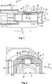
Im Folgenden ist der Aufbau eines erfindungsgemäßen Außengehäuses mit einer eingesetzten Halteklammer mit Bezug auf die
Das Außengehäuse
Die Aufnahme
Die Außengehäusewand
Das Außengehäuse
Der Führungskanal
Am von der Aufnahme
Der Aufnahmekanal
An der von der Aufnahme
Am zur Aufnahme
Die Außengehäusewand
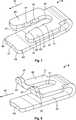
Die
Die Halteklammer
Der Schenkel
Die Halteklammer
Die Schenkel
Der Aufnahmekanal
Der Reibschluss zwischen dem Schenkel
Die lichte Weite
Die lichte Weite
Das Innengehäuse
Gegen die Montagerichtung M stößt der nach außen gerichtete Haltevorsprung
An der Dichtungsaufnahme
Das Innengehäuse
Die Halteklammern
Das Innengehäuse
Der Schenkel
Das freie Ende
Der Schenkel
Es ist prinzipiell möglich, die verschiedenen Formen der Vorsprünge
BezugszeichenlisteLIST OF REFERENCE NUMBERS
- 1, 1’1, 1 '
- Außengehäuseouter casing
- 33
- AußengehäusewandOuter housing wall
- 5, 5’5, 5 '
- Aufnahmeadmission
- 77
- Klammersitzclip seat
- 99
- Halteklammerretaining clip
- 1111
- Vorderes Ende der AufnahmeFront end of the recording
- 1313
- Hinteres Ende der AufnahmeRear end of the shot
- 1515
- Inneres des AußengehäusesInside of the outer casing
- 1717
- Mittenbereichmid-range
- 19, 19’19, 19 '
- Führungskanalguide channel
- 2121
- Hinteres Ende des AußengehäusesRear end of the outer housing
- 2323
- Zugangskanalaccess channel
- 2525
- Dichtungsaufnahmeseal Housing
- 2727
- DurchgangsbereichPassage area
- 2929
- Aufnahmekanalreceiving channel
- 3131
- Schenkelleg
- 3333
- Schenkelleg
- 3535
- Klemmtascheglassine envelopes
- 3737
- Werkzeugkanaltool channel
- 3939
- Ausnehmungrecess
- 4040
- InnengehäuseanschlagInside housing stop
- 4141
- Spitzetop
- 4343
- Freies EndeFree end
- 4545
- BasisBase
- 4747
- Vorsprunghead Start
- 4949
- Lichte Weite des AufnahmekanalsClear width of the receiving channel
- 5151
- Innenwändeinterior walls
- 5252
- Schenkelbreiteleg width
- 5353
- Lichte Weite des DurchgangsbereichsClear width of the passage area
- 55, 55’55, 55 '
- Anordnungarrangement
- 57, 57’57, 57 '
- Innengehäuseinner housing
- 5959
- Zentriervorsprungcentering
- 6161
- Haltevorsprungretaining projection
- 6363
- Dichtelementsealing element
- 6565
- Zentrale ÖffnungCentral opening
- 6767
- Innenrauminner space
- 6969
- Fixierzahnanchorage tooth
- 7171
- Gehäuseaufnahmehousing receptacle
- 7373
- Rastlaschesnap tab
- 7575
- Rastöffnunglatching opening
- 7777
- InnengehäuseendeInner housing end
- 8181
- Ausnehmungrecess
- 8383
- Zinkenprong
- 8585
- Verbreiterungwidening
- 8787
- Anschlagflächestop surface
- 8989
- Eckencorners
- 9191
- Wölbungbulge
- 9393
- Ende eines ZinkensEnd of a tine
- M, M’M, M '
- Montagerichtungmounting direction
- AA
- AußenOutside
- UU
- Umfangsrichtungcircumferentially
- SS
- Spreizungspread
Claims (15)
Translated fromGermanPriority Applications (1)
| Application Number | Priority Date | Filing Date | Title |
|---|---|---|---|
| DE102014207137.2ADE102014207137A1 (en) | 2014-04-14 | 2014-04-14 | An outer housing for an electrical connector, comprising a retaining clip for an inner housing, and an arrangement comprising an outer housing |
Applications Claiming Priority (1)
| Application Number | Priority Date | Filing Date | Title |
|---|---|---|---|
| DE102014207137.2ADE102014207137A1 (en) | 2014-04-14 | 2014-04-14 | An outer housing for an electrical connector, comprising a retaining clip for an inner housing, and an arrangement comprising an outer housing |
Publications (1)
| Publication Number | Publication Date |
|---|---|
| DE102014207137A1true DE102014207137A1 (en) | 2015-10-15 |
Family
ID=54193239
Family Applications (1)
| Application Number | Title | Priority Date | Filing Date |
|---|---|---|---|
| DE102014207137.2AWithdrawnDE102014207137A1 (en) | 2014-04-14 | 2014-04-14 | An outer housing for an electrical connector, comprising a retaining clip for an inner housing, and an arrangement comprising an outer housing |
Country Status (1)
| Country | Link |
|---|---|
| DE (1) | DE102014207137A1 (en) |
Cited By (2)
| Publication number | Priority date | Publication date | Assignee | Title |
|---|---|---|---|---|
| CN109473814A (en)* | 2017-09-07 | 2019-03-15 | 泰科电子(上海)有限公司 | Connection housing, housing assembly and electrical connector |
| CN112993690A (en)* | 2019-12-02 | 2021-06-18 | 安德烈·斯蒂尔股份两合公司 | Motor-driven gardening and/or forestry working appliance and plug connector for electrically connecting wire and plug tab thereof |
Citations (3)
| Publication number | Priority date | Publication date | Assignee | Title |
|---|---|---|---|---|
| DE9104985U1 (en)* | 1991-04-23 | 1991-08-22 | Interconnectron GmbH, 8360 Deggendorf | Electrical connector |
| DE102011087243B3 (en)* | 2011-11-28 | 2013-03-28 | Tyco Electronics Amp Gmbh | Electrical connector with contact protection |
| EP2736124A1 (en)* | 2012-11-26 | 2014-05-28 | Coninvers GmbH | Electrical connector with latched insulating body which can be detached with a tool |
- 2014
- 2014-04-14DEDE102014207137.2Apatent/DE102014207137A1/ennot_activeWithdrawn
Patent Citations (3)
| Publication number | Priority date | Publication date | Assignee | Title |
|---|---|---|---|---|
| DE9104985U1 (en)* | 1991-04-23 | 1991-08-22 | Interconnectron GmbH, 8360 Deggendorf | Electrical connector |
| DE102011087243B3 (en)* | 2011-11-28 | 2013-03-28 | Tyco Electronics Amp Gmbh | Electrical connector with contact protection |
| EP2736124A1 (en)* | 2012-11-26 | 2014-05-28 | Coninvers GmbH | Electrical connector with latched insulating body which can be detached with a tool |
Cited By (2)
| Publication number | Priority date | Publication date | Assignee | Title |
|---|---|---|---|---|
| CN109473814A (en)* | 2017-09-07 | 2019-03-15 | 泰科电子(上海)有限公司 | Connection housing, housing assembly and electrical connector |
| CN112993690A (en)* | 2019-12-02 | 2021-06-18 | 安德烈·斯蒂尔股份两合公司 | Motor-driven gardening and/or forestry working appliance and plug connector for electrically connecting wire and plug tab thereof |
Similar Documents
| Publication | Publication Date | Title |
|---|---|---|
| EP3345259B1 (en) | Support frame for connector module | |
| DE2407063C2 (en) | Socket for an electrical plug | |
| DE2553558C3 (en) | Electrical plug connection | |
| DE661023C (en) | Detachable coupling lock, in particular plug-in device for electrical or mechanical purposes | |
| DE19500102C2 (en) | Locking device for a connector | |
| EP3345251B1 (en) | Fixing frame for connector with a blade shaped fixing means | |
| EP1764875B1 (en) | Electrical connector with preloaded contacts blades | |
| DE2925938A1 (en) | ELECTRIC FLAT CONNECTOR | |
| DE102004054467A1 (en) | Securing part for a quick coupling | |
| EP3345257A1 (en) | Holding frame for plug connector modules | |
| DE102010008458A1 (en) | fastening device | |
| DE102015203489A1 (en) | Electrical connector with cable clamping device | |
| DE2210904B2 (en) | Electrical socket | |
| DE2149838C3 (en) | Electrical coupling element | |
| DE102010036003A1 (en) | Unit for fixing a cable | |
| DE202014103395U1 (en) | clamp | |
| DE1151578B (en) | Solder-free connector | |
| DE102014207137A1 (en) | An outer housing for an electrical connector, comprising a retaining clip for an inner housing, and an arrangement comprising an outer housing | |
| DE102014102790A1 (en) | Frame for cable glands, fasteners and cable entry system | |
| EP0822615A2 (en) | Electrical contact spring | |
| EP1248318B1 (en) | Electrical contact as well as lamphoder and connecting terminal with at least such a contact | |
| DE3909548C2 (en) | ||
| DE102005053566A1 (en) | Stamped and bent contact pin for power plug connection, has connection head and pin extension formed from metallic flat material, and flexible tongue arranged in connection head and producing clamping connection with terminal lead | |
| EP0892997B1 (en) | Cable plug connector | |
| DE102006022206B3 (en) | Plug-connector, has spring leg that is attached at one of two walls of contact part and staying in non-linked initial position under top angle to common axis of plug-through holes, where leg has contact point that impinges on contact pin |
Legal Events
| Date | Code | Title | Description |
|---|---|---|---|
| R012 | Request for examination validly filed | ||
| R083 | Amendment of/additions to inventor(s) | ||
| R016 | Response to examination communication | ||
| R082 | Change of representative | Representative=s name:GRUENECKER PATENT- UND RECHTSANWAELTE PARTG MB, DE | |
| R119 | Application deemed withdrawn, or ip right lapsed, due to non-payment of renewal fee |