DE102014203169A1 - Antenna with shielding device and manufacturing method - Google Patents
Antenna with shielding device and manufacturing methodDownload PDFInfo
- Publication number
- DE102014203169A1 DE102014203169A1DE102014203169.9ADE102014203169ADE102014203169A1DE 102014203169 A1DE102014203169 A1DE 102014203169A1DE 102014203169 ADE102014203169 ADE 102014203169ADE 102014203169 A1DE102014203169 A1DE 102014203169A1
- Authority
- DE
- Germany
- Prior art keywords
- sections
- coil device
- coil
- antenna
- cuts
- Prior art date
- Legal status (The legal status is an assumption and is not a legal conclusion. Google has not performed a legal analysis and makes no representation as to the accuracy of the status listed.)
- Ceased
Links
Images


Classifications
- H—ELECTRICITY
- H01—ELECTRIC ELEMENTS
- H01Q—ANTENNAS, i.e. RADIO AERIALS
- H01Q1/00—Details of, or arrangements associated with, antennas
- H01Q1/27—Adaptation for use in or on movable bodies
- H01Q1/273—Adaptation for carrying or wearing by persons or animals
- H—ELECTRICITY
- H01—ELECTRIC ELEMENTS
- H01F—MAGNETS; INDUCTANCES; TRANSFORMERS; SELECTION OF MATERIALS FOR THEIR MAGNETIC PROPERTIES
- H01F27/00—Details of transformers or inductances, in general
- H01F27/34—Special means for preventing or reducing unwanted electric or magnetic effects, e.g. no-load losses, reactive currents, harmonics, oscillations, leakage fields
- H01F27/36—Electric or magnetic shields or screens
- H01F27/363—Electric or magnetic shields or screens made of electrically conductive material
- H—ELECTRICITY
- H01—ELECTRIC ELEMENTS
- H01F—MAGNETS; INDUCTANCES; TRANSFORMERS; SELECTION OF MATERIALS FOR THEIR MAGNETIC PROPERTIES
- H01F38/00—Adaptations of transformers or inductances for specific applications or functions
- H01F38/14—Inductive couplings
- H—ELECTRICITY
- H01—ELECTRIC ELEMENTS
- H01Q—ANTENNAS, i.e. RADIO AERIALS
- H01Q1/00—Details of, or arrangements associated with, antennas
- H01Q1/52—Means for reducing coupling between antennas; Means for reducing coupling between an antenna and another structure
- H—ELECTRICITY
- H01—ELECTRIC ELEMENTS
- H01Q—ANTENNAS, i.e. RADIO AERIALS
- H01Q1/00—Details of, or arrangements associated with, antennas
- H01Q1/52—Means for reducing coupling between antennas; Means for reducing coupling between an antenna and another structure
- H01Q1/526—Electromagnetic shields
- H—ELECTRICITY
- H01—ELECTRIC ELEMENTS
- H01Q—ANTENNAS, i.e. RADIO AERIALS
- H01Q7/00—Loop antennas with a substantially uniform current distribution around the loop and having a directional radiation pattern in a plane perpendicular to the plane of the loop
- H—ELECTRICITY
- H04—ELECTRIC COMMUNICATION TECHNIQUE
- H04R—LOUDSPEAKERS, MICROPHONES, GRAMOPHONE PICK-UPS OR LIKE ACOUSTIC ELECTROMECHANICAL TRANSDUCERS; DEAF-AID SETS; PUBLIC ADDRESS SYSTEMS
- H04R25/00—Deaf-aid sets, i.e. electro-acoustic or electro-mechanical hearing aids; Electric tinnitus maskers providing an auditory perception
- H04R25/65—Housing parts, e.g. shells, tips or moulds, or their manufacture
- H04R25/658—Manufacture of housing parts
- H—ELECTRICITY
- H04—ELECTRIC COMMUNICATION TECHNIQUE
- H04B—TRANSMISSION
- H04B5/00—Near-field transmission systems, e.g. inductive or capacitive transmission systems
- H04B5/40—Near-field transmission systems, e.g. inductive or capacitive transmission systems characterised by components specially adapted for near-field transmission
- H04B5/43—Antennas
- Y—GENERAL TAGGING OF NEW TECHNOLOGICAL DEVELOPMENTS; GENERAL TAGGING OF CROSS-SECTIONAL TECHNOLOGIES SPANNING OVER SEVERAL SECTIONS OF THE IPC; TECHNICAL SUBJECTS COVERED BY FORMER USPC CROSS-REFERENCE ART COLLECTIONS [XRACs] AND DIGESTS
- Y10—TECHNICAL SUBJECTS COVERED BY FORMER USPC
- Y10T—TECHNICAL SUBJECTS COVERED BY FORMER US CLASSIFICATION
- Y10T29/00—Metal working
- Y10T29/49—Method of mechanical manufacture
- Y10T29/49002—Electrical device making
- Y10T29/49016—Antenna or wave energy "plumbing" making
Landscapes
- Engineering & Computer Science (AREA)
- Power Engineering (AREA)
- Manufacturing & Machinery (AREA)
- Physics & Mathematics (AREA)
- Health & Medical Sciences (AREA)
- General Health & Medical Sciences (AREA)
- Neurosurgery (AREA)
- Otolaryngology (AREA)
- Acoustics & Sound (AREA)
- Signal Processing (AREA)
- Electromagnetism (AREA)
- Shielding Devices Or Components To Electric Or Magnetic Fields (AREA)
Abstract
Translated fromGermanDescription
Translated fromGermanDie vorliegende Erfindung betrifft eine Antenne für ein Hörgerät mit einer im Wesentlichen zylindrischen Spulenvorrichtung als elektromagnetische Sende- und/oder Empfangseinheit sowie einer Schirmvorrichtung, die die Spulenvorrichtung umgibt und deren Grundkörper ein flexibles Substrat ist. Darüber hinaus betrifft die vorliegende Erfindung ein Verfahren zum Herstellen einer Antenne für ein Hörgerät.The present invention relates to an antenna for a hearing device having a substantially cylindrical coil device as an electromagnetic transmitting and / or receiving unit and a shielding device which surrounds the coil device and the base body is a flexible substrate. Moreover, the present invention relates to a method for producing an antenna for a hearing device.
Hörvorrichtungen besitzen oftmals Antennen für drahtlose Nahfeldübertragung. Solche Übertragungen werden beispielsweise zur Kommunikation mit Zusatzgeräten oder mit Geräten gleicher Bauart (z. B. binaurales Hörgerätesystem) verwendet. Unter einer Hörvorrichtung wird hier jedes im oder am Ohr tragbare, einen Schallreiz erzeugende Gerät, insbesondere ein Hörgerät, ein Headset, Kopfhörer und dergleichen verstanden.Hearing devices often have antennas for near-field wireless transmission. Such transmissions are used, for example, for communication with additional devices or with devices of the same type (eg binaural hearing device system). A hearing device is understood here to be any device which can be worn in or on the ear and generates a sound stimulus, in particular a hearing device, a headset, headphones and the like.
Hörgeräte sind tragbare Hörvorrichtungen, die zur Versorgung von Schwerhörenden dienen. Um den zahlreichen individuellen Bedürfnissen entgegenzukommen, werden unterschiedliche Bauformen von Hörgeräten wie Hinter-dem-Ohr-Hörgeräte (HdO), Hörgerät mit externem Hörer (RIC: receiver in the canal) und In-dem-Ohr-Hörgeräte (IdO), z.B. auch Concha-Hörgeräte oder Kanal-Hörgeräte (ITE, CIC), bereitgestellt. Die beispielhaft aufgeführten Hörgeräte werden am Außenohr oder im Gehörgang getragen. Darüber hinaus stehen auf dem Markt aber auch Knochenleitungshörhilfen, implantierbare oder vibrotaktile Hörhilfen zur Verfügung. Dabei erfolgt die Stimulation des geschädigten Gehörs entweder mechanisch oder elektrisch.Hearing aids are portable hearing aids that are used to care for the hearing impaired. In order to meet the numerous individual needs, different types of hearing aids such as behind-the-ear hearing aids (BTE), hearing aid with external receiver (RIC: receiver in the canal) and in-the-ear hearing aids (IDO), e.g. Concha hearing aids or canal hearing aids (ITE, CIC). The hearing aids listed by way of example are worn on the outer ear or in the ear canal. In addition, bone conduction hearing aids, implantable or vibrotactile hearing aids are also available on the market. The stimulation of the damaged hearing takes place either mechanically or electrically.
Hörgeräte besitzen prinzipiell als wesentliche Komponenten einen Eingangswandler, einen Verstärker und einen Ausgangswandler. Der Eingangswandler ist in der Regel ein Schallempfänger, z. B. ein Mikrofon, und/oder ein elektromagnetischer Empfänger, z. B. eine Induktionsspule. Der Ausgangswandler ist meist als elektroakustischer Wandler, z. B. Miniaturlautsprecher, oder als elektromechanischer Wandler, z. B. Knochenleitungshörer, realisiert. Der Verstärker ist üblicherweise in eine Signalverarbeitungseinheit integriert. Dieser prinzipielle Aufbau ist in
Zur drahtlosen Übertragung sind beim Empfänger wie auch beim Sender Antennen notwendig. Ungeschirmte Antennen sind sowohl gegen elektrische (E-Feld) als auch magnetische (H-Feld) Interferenzen empfindlich, die von nahegelegenen elektronischen Komponenten erzeugt werden. Derartige Störfelder oder Interferenzen führen zu einer Verschlechterung des drahtlosen Nutzsignals, sodass das Kommunikationssignal vom Sender durch den Empfänger unter Umständen nicht oder nur mit geringerer Qualität empfangen wird. Damit ist die Leistungsfähigkeit des drahtlosen Kommunikationssystems herabgesetzt.For wireless transmission antennas are necessary at the receiver as well as at the transmitter. Unshielded antennas are sensitive to both electrical (E-field) and magnetic (H-field) interferences generated by nearby electronic components. Such interference fields or interference lead to a deterioration of the wireless useful signal, so that the communication signal from the transmitter by the receiver may not or only with lower quality is received. This degrades the performance of the wireless communication system.
Zur Vermeidung derartiger Degradationen werden ungeschirmte Antennen für Drahtlosverbindungen in der Regel von elektronischen Komponenten, die elektrische und magnetische Störungen emittieren, beabstandet. Dies beeinträchtigt die Freiheit bei der Platzierung der Antennen in der Hörvorrichtung beziehungsweise dem Hörgerät, insbesondere dem Hinter-dem-Ohr-Hörgerät. Bei einigen Hörgeräten ist es aber aus Gestaltungsgründen notwendig, dass die Antenne zur Drahtlosübertragung näher an einer elektronischen Komponente angeordnet ist, die ein elektrisches oder magnetisches Störfeld produziert. In solchen Fällen sind meist Abschirmungen in Form von Abdeckungen oder kleinen Boxen vorgesehen. Spezifisch sind dann jene Elektronikbauteile abgeschirmt beziehungsweise ummantelt, die die unerwünschten elektrischen und magnetischen Störfelder produzieren. Aufgrund der unterschiedlichen Bauarten der Hörvorrichtungen und deren Elektronikkomponenten sind daher zahlreiche Schirmabdeckungen unterschiedlicher Größe und Gestalt bereitzustellen.To avoid such degradations, unshielded antennas for wireless connections are typically spaced from electronic components that emit electrical and magnetic disturbances. This impairs the freedom in the placement of the antennas in the hearing device or the hearing device, in particular the behind-the-ear hearing device. For some hearing aids, however, it is necessary for design reasons that the antenna for wireless transmission is located closer to an electronic component that produces an electrical or magnetic interference field. In such cases shields are usually provided in the form of covers or small boxes. Specifically, then those electronic components are shielded or encased, which produce the unwanted electrical and magnetic interference fields. Due to the different types of hearing devices and their electronic components therefore numerous screen covers of different size and shape are provided.
Aus der Druckschrift
Die Aufgabe der vorliegenden Erfindung besteht darin, eine Antenne für eine Hörvorrichtung vorzuschlagen, die auf einfache Weise mit einer Schirmvorrichtung versehen werden kann. Darüber hinaus soll ein entsprechendes Herstellungsverfahren für eine Antenne einer Hörvorrichtung angegeben werden.The object of the present invention is to propose an antenna for a hearing device, which can be provided in a simple manner with a screen device. In addition, a corresponding manufacturing method for an antenna of a hearing device is to be specified.
Erfindungsgemäß wird diese Aufgabe gelöst durch eine Antenne für ein Hörgerät mit einer im Wesentlichen zylindrischen Spulenvorrichtung als elektromagnetische Sende- und/oder Empfangseinheit und einer Schirmvorrichtung, die die Spulenvorrichtung umgibt und deren Grundkörper ein flexibles Substrat ist, wobei die Schirmvorrichtung einteilig gebildet und durch zwei Schnitte, die an keinem ihrer Enden an den Rand des Substrats reichen, in drei Abschnitte unterteilt ist und die Spulenvorrichtung so durch die zwei Schnitte der Schirmvorrichtung gesteckt ist, dass jeder der Abschnitte die Spulenvorrichtung in Umfangsrichtung nur teilweise umgibt.According to the invention this object is achieved by an antenna for a hearing aid with a in Substantially cylindrical coil device as an electromagnetic transmitting and / or receiving unit and a shielding device surrounding the coil device and the base body is a flexible substrate, wherein the shielding device formed integrally and by two cuts that do not extend at any of its ends to the edge of the substrate in three sections is divided and the coil device is inserted through the two sections of the screen device, that each of the sections surrounds the coil device only partially in the circumferential direction.
Darüber hinaus wird erfindungsgemäß bereitgestellt ein Verfahren zum Herstellen einer Antenne für ein Hörgerät durch Bereitstellen einer im Wesentlichen zylindrischen Spulenvorrichtung als elektromagnetische Sende- und/ oder Empfangseinheit und Bereitstellen einer Schirmvorrichtung zum Schirmen der Spulenvorrichtung, wobei der Grundkörper der Schirmvorrichtung ein flexibles Substrat ist, wobei die Schirmvorrichtung einteilig gebildet und durch zwei Schnitte, die an keinem ihrer Enden an den Rand des Substrats reichen, in drei Abschnitte unterteilt ist, und die Spulenvorrichtung so durch die zwei Schnitte der Schirmvorrichtung gesteckt wird, dass jeder der Abschnitte die Spulenvorrichtung in Umfangsrichtung nur teilweise umgibt.In addition, according to the invention, a method is provided for producing an antenna for a hearing aid by providing a substantially cylindrical coil device as an electromagnetic transmitting and / or receiving unit and providing a shielding device for shielding the coil device, wherein the base body of the shielding device is a flexible substrate, wherein the Screen device is formed in one piece and divided into three sections by two sections that do not extend at any of its ends to the edge of the substrate, and the coil device is inserted through the two sections of the screen device, that each of the sections surrounding the coil device only partially in the circumferential direction ,
In vorteilhafter Weise wird also zum Schirmen einer Spulenvorrichtung eine Schirmvorrichtung auf der Basis eines flexiblen Substrats verwendet, welches durch zwei Schnitte in drei Abschnitte geteilt ist. Für die Montage wird dann nur die Spulenvorrichtung durch die beiden Schnitte geführt, sodass die Schirmvorrichtung auf der Spulenvorrichtung steckt und diese bereichsweise umgibt. Im Wesentlichen umgibt ein mittlerer Bereich der Schirmvorrichtung die Spulenvorrichtung an einem Abschnitt ihres Außenumfangs, während die äußeren beiden Abschnitte der Schirmvorrichtung die Spulenvorrichtung an gegenüberliegenden Umfangsbereichen umgeben. Somit ist zum einen eine sehr einfache Herstellung der Schirmvorrichtung und zum anderen eine wenig aufwändige Montage auf die Spulenvorrichtung möglich.Advantageously, therefore, a shield device based on a flexible substrate is used for shielding a coil device, which is divided by two sections into three sections. For assembly, only the coil device is then guided through the two sections, so that the shielding device is inserted on the coil device and surrounds these regions. In essence, a central portion of the shielding device surrounds the coil device at a portion of its outer periphery, while the outer two portions of the shielding device surround the coil device at opposite circumferential portions. Thus, on the one hand, a very simple production of the shielding device and, on the other hand, a little expensive assembly on the coil device is possible.
Bei einer Ausführungsform besitzt die Schirmvorrichtung in allen drei Abschnitten ein elektrisch zusammenhängendes Leitergebilde. Damit ist eine Schirmung durch alle drei Abschnitte gegeben. Alternativ kann das Leitergebilde aber auch beispielsweise nur in dem mittleren Abschnitt vorgesehen sein.In one embodiment, the shielding device has an electrically contiguous conductive structure in all three sections. This shielding is given by all three sections. Alternatively, however, the conductor structure may also be provided, for example, only in the middle section.
Das Leitergebilde kann zahlreiche parallele Leiterbahnen aufweisen. Diese lassen sich leicht herstellen und sorgen für eine effiziente Schirmwirkung.The conductor structure can have numerous parallel tracks. These are easy to produce and provide an efficient shielding effect.
In einer Ausgestaltung sind die Schnitte der Schirmvorrichtung parallel zueinander und die Leiterbahnen parallel zu den Schnitten angeordnet. Dies hat den Vorteil, dass die Position der Schnitte verändert werden kann, ohne dass das Leitergebilde selbst verändert werden müsste. Somit lassen sich unterschiedlich lange Schirmvorrichtungen für verschieden lange Spulenvorrichtungen aus ein und demselben Bandmaterial nur durch Abschneiden und Einbringen der Schnitte erzeugen.In one embodiment, the sections of the screen device are arranged parallel to one another and the conductor tracks are arranged parallel to the sections. This has the advantage that the position of the cuts can be changed without the circuit structure itself would have to be changed. Thus, shielding devices of different lengths for one and the same strip material can only be produced by cutting and inserting the cuts of different lengths.
Vorzugsweise sind die drei Abschnitte der Schirmvorrichtung in axialer Richtung der im Wesentlichen zylinderförmigen Spulenvorrichtung hintereinander angeordnet, und die äußeren beiden der drei Abschnitte besitzen jeweils ein erstes Kontaktfeld zum direkten Kontaktieren eines Masseanschlusses, wobei die Kontaktfelder mit Leitern der Schirmvorrichtung elektrisch verbunden sind. Damit liegen die Kontaktfelder für die Schirmvorrichtung am Außenumfang der Antenne, weshalb sich die Schirmvorrichtung leicht mit Masse verbinden lässt.Preferably, the three sections of the shielding device are arranged one behind the other in the axial direction of the substantially cylindrical coil device, and the outer two of the three sections each have a first contact pad for directly contacting a ground terminal, wherein the contact pads are electrically connected to conductors of the shielding device. Thus, the contact fields for the screen device are on the outer circumference of the antenna, which is why the screen device can be easily connected to ground.
Darüber hinaus können die äußeren beiden der drei Abschnitte jeweils ein zweites Kontaktfeld zum direkten Kontaktieren eines Leiters der Spulenvorrichtung besitzen. Wenn die ersten und zweiten Kontaktfelder dabei möglichst parallel nach außen gewandt sind, ergibt damit eine SMD-Bauform der Antenne. Somit lässt sich eine geschirmte Antenne für eine wirtschaftlich vorteilhafte SMD-Produktion bereitstellen.In addition, the outer two of the three sections may each have a second contact pad for directly contacting a conductor of the coil device. If the first and second contact fields are turned outwards as parallel as possible, this results in an SMD design of the antenna. Thus, a shielded antenna can be provided for economically advantageous SMD production.
Die Schirmvorrichtung kann eine flexible Leiterplatte mit dem flexiblen Substrat aufweisen. Derartige flexible Leiterplatten sind kostengünstig in der Herstellung und als Massenware erhältlich. Insbesondere kann die flexible Leiterplatte eine gedruckte Leiterplatte sein.The shielding device may comprise a flexible printed circuit board with the flexible substrate. Such flexible printed circuit boards are inexpensive to manufacture and available as a commodity. In particular, the flexible printed circuit board may be a printed circuit board.
Für die Herstellung eines SMD-Bauteils ist es besonders vorteilhaft, wenn die Spule einen Kern aufweist, dessen Querschnitt ein Kreissegment ist. Damit besitzt der Kern eine flache Seite parallel zu seiner Achse. Diese flache Seite lässt sich dazu nutzen, die Kontaktfelder der Schirmvorrichtung parallel anzuordnen, sodass ein stabiles SMD-Bauteil entsteht.For the production of an SMD component, it is particularly advantageous if the coil has a core whose cross-section is a circle segment. Thus, the core has a flat side parallel to its axis. This flat side can be used to arrange the contact fields of the shield device in parallel, so that a stable SMD component is created.
Die vorliegende Erfindung wird anhand der beigefügten Zeichnungen näher erläutert, in denen zeigen:The present invention will be further explained with reference to the accompanying drawings, in which:
Die nachfolgend näher geschilderten Ausführungsbeispiele stellen bevorzugte Ausführungsformen der vorliegenden Erfindung dar.The embodiments described in more detail below represent preferred embodiments of the present invention.
Eine Hörvorrichtung und insbesondere ein Hörgerät gemäß dem Beispiel von
Soll beispielsweise eine Antenne zur drahtlosen Signalübertragung in einem Hörgerät in der Nähe eines Verstärkerbausteins angeordnet werden können, so sollte sie entsprechend geschirmt sein, um eine hohe Qualität der drahtlosen Übertragung gewährleisten zu können. Für die Schirmung ist es ausschlaggebend, das E-Feld und H-Feld in ausreichendem Maße abhalten zu können. Gleichzeitig sollte die Schirmung leicht herzustellen und leicht zu montieren sein. Ferner ist es günstig, wenn die Schirmung für unterschiedliche Bauarten einer Antennenspule (Spulenvorrichtung) verwendet werden kann, um auch Instrumente niederpreisigerer Plattformen bedienen zu können. Spulenvorrichtungen für Hörgeräte besitzen beispielsweise eine typische Länge von 5 bis 6 mm. Darüber hinaus wäre es vorteilhaft, wenn die geschirmten Antennen als SMD-Bauteile zur Verfügung stünden.For example, if an antenna for wireless signal transmission in a hearing aid in the vicinity of an amplifier module can be arranged, it should be shielded accordingly in order to ensure a high quality of wireless transmission can. For the shielding, it is crucial to be able to hold the E-field and H-field to a sufficient extent. At the same time, the shielding should be easy to manufacture and easy to assemble. Furthermore, it is favorable if the shielding can be used for different types of antenna coil (coil device) in order to be able to operate instruments of lower price platforms as well. Coil devices for hearing aids, for example, have a typical length of 5 to 6 mm. In addition, it would be advantageous if the shielded antennas were available as SMD components.
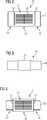
Um all diesen Forderungen (gegebenenfalls auch nur einer oder mehreren davon) gerecht zu werden, wird die in den
In das Substrat
Das Substrat
Leiterbahnen
Zur Montage der Schirmvorrichtung
In der Draufsicht von
Die Längsseitenansicht von
Wie
Wie schließlich aus der Unterseitenansicht von
In dem vorliegenden Beispiel ist die Antenne, d. h. die Spulenvorrichtung
Erfindungsgemäß wird also eine Antenne mit hülsenförmiger Abschirmung bereitgestellt, wobei vorzugsweise eine flexible, gedruckte Leiterplatte um die Spulenvorrichtung appliziert wird. Die Abschirmschicht ist dabei nur teilweise um die Antenne gewickelt.Thus, according to the invention, an antenna with sleeve-shaped shielding is provided, wherein preferably a flexible, printed circuit board is applied around the coil device. The shielding layer is only partially wound around the antenna.
Die Antenne mit hülsenförmiger Abschirmung ist weniger empfindlich gegenüber elektrischen und magnetischen Interferenzen als ungeschirmte Antennen und sorgt daher für ein besseres Signal-zu-Rausch-Verhältnis. Damit lässt sich die Entfernung für drahtlose Kommunikation zwischen Geräten erhöhen.The sleeve-shaped antenna is less sensitive to electrical and magnetic interference than unshielded antennas for a better signal-to-noise ratio. This can increase the distance for wireless communication between devices.
Das einfache Design der Schirmvorrichtung ermöglicht den Einsatz für unterschiedliche Spulenvorrichtungen und somit für unterschiedliche Hörgerätemodelle. Auf individuelle Schirmabdeckungen kann somit verzichtet werden. Dies reduziert die Anzahl der Einzelteile bei der Hörgerätmontage. Darüber hinaus lässt sich die erfindungsgemäße Abschirmung für die Spulen in Massenproduktion herstellen. Ferner lassen sich mit der erfindungsgemäßen Spulenschirmung auch voluminöse Abschirmboxen für die Verstärker von Hörgeräten vermeiden, sodass letztlich die Hörgeräte miniaturisiert werden können.The simple design of the shield device allows the use for different coil devices and thus for different hearing aid models. Individual screen covers can thus be dispensed with. This reduces the number of parts in Hearing Aid Assembly. In addition, the inventive shield for the coils can be mass produced. Furthermore, voluminous shielding boxes for the amplifiers of hearing aids can be avoided with the coil shield according to the invention, so that ultimately the hearing aids can be miniaturized.
ZITATE ENTHALTEN IN DER BESCHREIBUNG QUOTES INCLUDE IN THE DESCRIPTION
Diese Liste der vom Anmelder aufgeführten Dokumente wurde automatisiert erzeugt und ist ausschließlich zur besseren Information des Lesers aufgenommen. Die Liste ist nicht Bestandteil der deutschen Patent- bzw. Gebrauchsmusteranmeldung. Das DPMA übernimmt keinerlei Haftung für etwaige Fehler oder Auslassungen.This list of the documents listed by the applicant has been generated automatically and is included solely for the better information of the reader. The list is not part of the German patent or utility model application. The DPMA assumes no liability for any errors or omissions.
Zitierte PatentliteraturCited patent literature
- US 7592964 B2[0007]US 7592964 B2[0007]
Claims (10)
Translated fromGermanPriority Applications (4)
| Application Number | Priority Date | Filing Date | Title |
|---|---|---|---|
| DE102014203169.9ADE102014203169A1 (en) | 2014-02-21 | 2014-02-21 | Antenna with shielding device and manufacturing method |
| EP15151950.1AEP2911312B1 (en) | 2014-02-21 | 2015-01-21 | Antenna with screening device and manufacturing method |
| DK15151950.1TDK2911312T3 (en) | 2014-02-21 | 2015-01-21 | ANTENNA WITH SCREEN FITTING AND PROCEDURE FOR ITS MANUFACTURING |
| US14/628,447US9559409B2 (en) | 2014-02-21 | 2015-02-23 | Antenna with shielding apparatus and manufacturing method |
Applications Claiming Priority (1)
| Application Number | Priority Date | Filing Date | Title |
|---|---|---|---|
| DE102014203169.9ADE102014203169A1 (en) | 2014-02-21 | 2014-02-21 | Antenna with shielding device and manufacturing method |
Publications (1)
| Publication Number | Publication Date |
|---|---|
| DE102014203169A1true DE102014203169A1 (en) | 2015-09-10 |
Family
ID=52394139
Family Applications (1)
| Application Number | Title | Priority Date | Filing Date |
|---|---|---|---|
| DE102014203169.9ACeasedDE102014203169A1 (en) | 2014-02-21 | 2014-02-21 | Antenna with shielding device and manufacturing method |
Country Status (4)
| Country | Link |
|---|---|
| US (1) | US9559409B2 (en) |
| EP (1) | EP2911312B1 (en) |
| DE (1) | DE102014203169A1 (en) |
| DK (1) | DK2911312T3 (en) |
Families Citing this family (2)
| Publication number | Priority date | Publication date | Assignee | Title |
|---|---|---|---|---|
| DK3269155T3 (en)* | 2015-03-13 | 2019-04-15 | Sivantos Pte Ltd | Binaural hearing aid system |
| CN112367092B (en)* | 2020-11-10 | 2021-12-10 | 广东信测科技有限公司 | Energy-saving anti-interference 5G signal receiving device |
Citations (8)
| Publication number | Priority date | Publication date | Assignee | Title |
|---|---|---|---|---|
| JP2002117383A (en)* | 2000-08-01 | 2002-04-19 | Mitsubishi Materials Corp | Antenna coil for rfid and its manufacturing method |
| US6940466B2 (en)* | 2003-11-25 | 2005-09-06 | Starkey Laboratories, Inc. | Enhanced magnetic field communication system |
| JP2008028642A (en)* | 2006-07-20 | 2008-02-07 | Murata Mfg Co Ltd | Magnetic material antenna and antenna device |
| US7592964B2 (en) | 2005-11-17 | 2009-09-22 | Oticon A/S | Shielded coil for inductive wireless applications |
| DE102008022127A1 (en)* | 2008-05-05 | 2009-11-12 | Siemens Medical Instruments Pte. Ltd. | Method for reducing body effects of hearing aid carrier on high frequency antenna e.g. horizontal magnetic loop antenna, in hearing aid, involves adjusting antenna matched to frequency that differs from operating frequency of radio system |
| US20100309081A1 (en)* | 2007-12-18 | 2010-12-09 | Murata Manufacturing Co., Ltd. | Magnetic material antenna and antenna device |
| DE102010024439A1 (en)* | 2009-06-22 | 2011-01-13 | Murata Manufacturing Co., Ltd., Nagaokakyo-shi | The antenna device |
| JP2011119819A (en)* | 2009-12-01 | 2011-06-16 | Murata Mfg Co Ltd | Magnetic body antenna, and portable terminal |
Family Cites Families (5)
| Publication number | Priority date | Publication date | Assignee | Title |
|---|---|---|---|---|
| US5981920A (en)* | 1997-09-12 | 1999-11-09 | Ppg Industries Ohio, Inc. | Furnace for heating glass sheets |
| WO2001052598A1 (en)* | 2000-01-13 | 2001-07-19 | Sonionmicrotronic Nederland B.V. | Packaging and rf shielding for telecoils |
| DE102007042592A1 (en)* | 2007-09-07 | 2009-03-26 | Siemens Medical Instruments Pte. Ltd. | Transmission device for a hearing device with foil conductor shield and self-shielded coil |
| DE102007055385B4 (en)* | 2007-11-20 | 2009-12-03 | Siemens Medical Instruments Pte. Ltd. | Shielding device for a hearing aid |
| US8761423B2 (en)* | 2011-11-23 | 2014-06-24 | Insound Medical, Inc. | Canal hearing devices and batteries for use with same |
- 2014
- 2014-02-21DEDE102014203169.9Apatent/DE102014203169A1/ennot_activeCeased
- 2015
- 2015-01-21EPEP15151950.1Apatent/EP2911312B1/enactiveActive
- 2015-01-21DKDK15151950.1Tpatent/DK2911312T3/enactive
- 2015-02-23USUS14/628,447patent/US9559409B2/enactiveActive
Patent Citations (8)
| Publication number | Priority date | Publication date | Assignee | Title |
|---|---|---|---|---|
| JP2002117383A (en)* | 2000-08-01 | 2002-04-19 | Mitsubishi Materials Corp | Antenna coil for rfid and its manufacturing method |
| US6940466B2 (en)* | 2003-11-25 | 2005-09-06 | Starkey Laboratories, Inc. | Enhanced magnetic field communication system |
| US7592964B2 (en) | 2005-11-17 | 2009-09-22 | Oticon A/S | Shielded coil for inductive wireless applications |
| JP2008028642A (en)* | 2006-07-20 | 2008-02-07 | Murata Mfg Co Ltd | Magnetic material antenna and antenna device |
| US20100309081A1 (en)* | 2007-12-18 | 2010-12-09 | Murata Manufacturing Co., Ltd. | Magnetic material antenna and antenna device |
| DE102008022127A1 (en)* | 2008-05-05 | 2009-11-12 | Siemens Medical Instruments Pte. Ltd. | Method for reducing body effects of hearing aid carrier on high frequency antenna e.g. horizontal magnetic loop antenna, in hearing aid, involves adjusting antenna matched to frequency that differs from operating frequency of radio system |
| DE102010024439A1 (en)* | 2009-06-22 | 2011-01-13 | Murata Manufacturing Co., Ltd., Nagaokakyo-shi | The antenna device |
| JP2011119819A (en)* | 2009-12-01 | 2011-06-16 | Murata Mfg Co Ltd | Magnetic body antenna, and portable terminal |
Also Published As
| Publication number | Publication date |
|---|---|
| US9559409B2 (en) | 2017-01-31 |
| DK2911312T3 (en) | 2018-07-16 |
| EP2911312B1 (en) | 2018-03-28 |
| EP2911312A1 (en) | 2015-08-26 |
| US20150244065A1 (en) | 2015-08-27 |
Similar Documents
| Publication | Publication Date | Title |
|---|---|---|
| EP3413587B1 (en) | Hearing aid, in particular behind the ear hearing aid | |
| EP2932560B2 (en) | Folded dipol for hearing aid | |
| EP3427339B1 (en) | Antenna | |
| EP2811761B1 (en) | Antenna device for hearing instruments | |
| EP2932559B1 (en) | Modular antenna for hearing aids | |
| EP3567672B1 (en) | Hearing aid with integrated antenna and electronics frame | |
| EP3322032B1 (en) | Hearing aid with integrated antenna and electronics frame | |
| EP3490272B1 (en) | Batch of listening devices and method for producing a batch of listening devices | |
| DE102007007800B3 (en) | Hearing device with receiver compensation coil | |
| DE102016207844A1 (en) | hearing Aid | |
| EP2034770B1 (en) | Transfer device for a hearing aid with shielded film conductor | |
| DE102021201095A1 (en) | Space-saving antenna for a hearing instrument | |
| EP3614494B1 (en) | Performant magnetically inductive antenna for a hearing aid | |
| EP2911312B1 (en) | Antenna with screening device and manufacturing method | |
| EP3836565B1 (en) | Circuit board for a hearing device | |
| WO2021099038A1 (en) | Method for producing a hearing aid and hearing aid | |
| WO2018024392A1 (en) | Hearing aid comprising an rf antenna | |
| DE102017220187A1 (en) | hearing aid | |
| DE102006049469B4 (en) | Hearing aid with live metal strap | |
| EP4104458B1 (en) | Space efficient magnetic-inductive antenna for hearing aid | |
| DE102021214085B4 (en) | Space-saving antenna for a hearing instrument | |
| DE202020105891U1 (en) | Acoustic microphone with integrated magnetic transducer | |
| DE102009018884A1 (en) | Earpiece for use in e.g. hearing device for hearing impaired person, has flexible printed board provided with outer- and inner contacts, which are electrically connected with each other in pairs | |
| DE102009008618A1 (en) | Hearing device for use by hearing impaired person, has ferrite sleeve, ferrite ring, and conductive coating provided as electro magnetic coupling reducing units in borehole of carrier device, for reducing electro magnetic coupling in wire |
Legal Events
| Date | Code | Title | Description |
|---|---|---|---|
| R012 | Request for examination validly filed | ||
| R082 | Change of representative | Representative=s name:FDST PATENTANWAELTE FREIER DOERR STAMMLER TSCH, DE | |
| R082 | Change of representative | Representative=s name:FDST PATENTANWAELTE FREIER DOERR STAMMLER TSCH, DE | |
| R081 | Change of applicant/patentee | Owner name:SIVANTOS PTE. LTD., SG Free format text:FORMER OWNER: SIEMENS MEDICAL INSTRUMENTS PTE. LTD., SINGAPORE, SG | |
| R082 | Change of representative | Representative=s name:FDST PATENTANWAELTE FREIER DOERR STAMMLER TSCH, DE | |
| R002 | Refusal decision in examination/registration proceedings | ||
| R003 | Refusal decision now final |