DE102014119010A1 - Intraocular lens with integrated single-lens telescope integrated in the optical part - Google Patents
Intraocular lens with integrated single-lens telescope integrated in the optical partDownload PDFInfo
- Publication number
- DE102014119010A1 DE102014119010A1DE102014119010.6ADE102014119010ADE102014119010A1DE 102014119010 A1DE102014119010 A1DE 102014119010A1DE 102014119010 ADE102014119010 ADE 102014119010ADE 102014119010 A1DE102014119010 A1DE 102014119010A1
- Authority
- DE
- Germany
- Prior art keywords
- telescope
- intraocular lens
- imaging element
- incident light
- lens
- Prior art date
- Legal status (The legal status is an assumption and is not a legal conclusion. Google has not performed a legal analysis and makes no representation as to the accuracy of the status listed.)
- Withdrawn
Links
Images


Classifications
- A—HUMAN NECESSITIES
- A61—MEDICAL OR VETERINARY SCIENCE; HYGIENE
- A61F—FILTERS IMPLANTABLE INTO BLOOD VESSELS; PROSTHESES; DEVICES PROVIDING PATENCY TO, OR PREVENTING COLLAPSING OF, TUBULAR STRUCTURES OF THE BODY, e.g. STENTS; ORTHOPAEDIC, NURSING OR CONTRACEPTIVE DEVICES; FOMENTATION; TREATMENT OR PROTECTION OF EYES OR EARS; BANDAGES, DRESSINGS OR ABSORBENT PADS; FIRST-AID KITS
- A61F2/00—Filters implantable into blood vessels; Prostheses, i.e. artificial substitutes or replacements for parts of the body; Appliances for connecting them with the body; Devices providing patency to, or preventing collapsing of, tubular structures of the body, e.g. stents
- A61F2/02—Prostheses implantable into the body
- A61F2/14—Eye parts, e.g. lenses or corneal implants; Artificial eyes
- A61F2/16—Intraocular lenses
- A61F2/1613—Intraocular lenses having special lens configurations, e.g. multipart lenses; having particular optical properties, e.g. pseudo-accommodative lenses, lenses having aberration corrections, diffractive lenses, lenses for variably absorbing electromagnetic radiation, lenses having variable focus
- A61F2/1648—Multipart lenses
- A61F2/1651—Multipart lenses comprising a telescope
- A—HUMAN NECESSITIES
- A61—MEDICAL OR VETERINARY SCIENCE; HYGIENE
- A61F—FILTERS IMPLANTABLE INTO BLOOD VESSELS; PROSTHESES; DEVICES PROVIDING PATENCY TO, OR PREVENTING COLLAPSING OF, TUBULAR STRUCTURES OF THE BODY, e.g. STENTS; ORTHOPAEDIC, NURSING OR CONTRACEPTIVE DEVICES; FOMENTATION; TREATMENT OR PROTECTION OF EYES OR EARS; BANDAGES, DRESSINGS OR ABSORBENT PADS; FIRST-AID KITS
- A61F2/00—Filters implantable into blood vessels; Prostheses, i.e. artificial substitutes or replacements for parts of the body; Appliances for connecting them with the body; Devices providing patency to, or preventing collapsing of, tubular structures of the body, e.g. stents
- A61F2/02—Prostheses implantable into the body
- A61F2/14—Eye parts, e.g. lenses or corneal implants; Artificial eyes
- A61F2/16—Intraocular lenses
- A61F2002/1681—Intraocular lenses having supporting structure for lens, e.g. haptics
- A61F2002/1683—Intraocular lenses having supporting structure for lens, e.g. haptics having filiform haptics
- A—HUMAN NECESSITIES
- A61—MEDICAL OR VETERINARY SCIENCE; HYGIENE
- A61F—FILTERS IMPLANTABLE INTO BLOOD VESSELS; PROSTHESES; DEVICES PROVIDING PATENCY TO, OR PREVENTING COLLAPSING OF, TUBULAR STRUCTURES OF THE BODY, e.g. STENTS; ORTHOPAEDIC, NURSING OR CONTRACEPTIVE DEVICES; FOMENTATION; TREATMENT OR PROTECTION OF EYES OR EARS; BANDAGES, DRESSINGS OR ABSORBENT PADS; FIRST-AID KITS
- A61F2/00—Filters implantable into blood vessels; Prostheses, i.e. artificial substitutes or replacements for parts of the body; Appliances for connecting them with the body; Devices providing patency to, or preventing collapsing of, tubular structures of the body, e.g. stents
- A61F2/02—Prostheses implantable into the body
- A61F2/14—Eye parts, e.g. lenses or corneal implants; Artificial eyes
- A61F2/16—Intraocular lenses
- A61F2002/1681—Intraocular lenses having supporting structure for lens, e.g. haptics
- A61F2002/1689—Intraocular lenses having supporting structure for lens, e.g. haptics having plate-haptics
- A—HUMAN NECESSITIES
- A61—MEDICAL OR VETERINARY SCIENCE; HYGIENE
- A61F—FILTERS IMPLANTABLE INTO BLOOD VESSELS; PROSTHESES; DEVICES PROVIDING PATENCY TO, OR PREVENTING COLLAPSING OF, TUBULAR STRUCTURES OF THE BODY, e.g. STENTS; ORTHOPAEDIC, NURSING OR CONTRACEPTIVE DEVICES; FOMENTATION; TREATMENT OR PROTECTION OF EYES OR EARS; BANDAGES, DRESSINGS OR ABSORBENT PADS; FIRST-AID KITS
- A61F2250/00—Special features of prostheses classified in groups A61F2/00 - A61F2/26 or A61F2/82 or A61F9/00 or A61F11/00 or subgroups thereof
- A61F2250/0014—Special features of prostheses classified in groups A61F2/00 - A61F2/26 or A61F2/82 or A61F9/00 or A61F11/00 or subgroups thereof having different values of a given property or geometrical feature, e.g. mechanical property or material property, at different locations within the same prosthesis
- A61F2250/0053—Special features of prostheses classified in groups A61F2/00 - A61F2/26 or A61F2/82 or A61F9/00 or A61F11/00 or subgroups thereof having different values of a given property or geometrical feature, e.g. mechanical property or material property, at different locations within the same prosthesis differing in optical properties
Landscapes
- Health & Medical Sciences (AREA)
- Ophthalmology & Optometry (AREA)
- Cardiology (AREA)
- Oral & Maxillofacial Surgery (AREA)
- Transplantation (AREA)
- Engineering & Computer Science (AREA)
- Biomedical Technology (AREA)
- Heart & Thoracic Surgery (AREA)
- Vascular Medicine (AREA)
- Life Sciences & Earth Sciences (AREA)
- Animal Behavior & Ethology (AREA)
- General Health & Medical Sciences (AREA)
- Public Health (AREA)
- Veterinary Medicine (AREA)
- Prostheses (AREA)
Abstract
Translated fromGermanDescription
Translated fromGermanDie Erfindung betrifft eine Intraokularlinse mit einem optischen Teil und einem daran anschließenden haptischen Teil, wobei der optische Teil ein optisch abbildendes Element und ein Teleskop aufweist.The invention relates to an intraocular lens having an optical part and an adjoining haptic part, wherein the optical part has an optically imaging element and a telescope.
Stand der TechnikState of the art
Das menschliche Auge kann aufgrund seines relativ komplexen Aufbaus und somit auch insbesondere der zur optischen Abbildung vorgesehenen Teile und/oder anderweitiger Einflussfaktoren mit unterschiedlichsten Sehfehlern behaftet sein. Diese können individuell in der Stärke unterschiedlich ausgeprägt sein, andererseits kann auch eine Mehrzahl unterschiedlicher Sehfehler in einem Auge vorliegen.Due to its relatively complex structure and thus in particular the parts intended for optical imaging and / or other influencing factors, the human eye may be afflicted with a wide variety of vision defects. These can be different in strength individually, on the other hand, a plurality of different vision defects in one eye can be present.
Augenlinsen zur Korrektur von Sehfehlern sind in Form von Intraokularlinsen in vielfältigsten Ausgestaltungen bekannt.Eye lenses for the correction of visual defects are known in the form of intraocular lenses in various designs.
Eine derartige Intraokularlinse ist beispielsweise aus der
Bei der bekannten Intraokularlinse ist der Aufbau jedoch äußerst komplex und die Intraokularlinse ist schwierig herzustellen. Denn die Intraokularlinse benötigt mehrere separate Teile, und zwar einerseits ein Körperelement, das konvex-konvex oder konvex-planar ausgestaltet sein kann. Zentral mittig weist dieses Körperelement eine durchgehende Bohrung auf, in welcher separate und beabstandet zueinander angeordnete Linsenelemente des Teleskops positioniert sind. Es kann vorgesehen sein, dass ein Linsenelement einstückig mit dem Körperelement ausgebildet ist. Das zweite Linsenelement muss jedoch zwangsweise stets als separates Teil bereitgestellt werden, da in einem Hohlraum zwischen den beiden Linsenelementen eine Gasfüllung eingebracht werden muss und auch zwangsweise ein derartiger Hohlraum ausgebildet werden muss. Durch diese Ausgestaltung ist die Positionierung der beiden konvexen Linsen zueinander äußerst schwierig und dauerhaft positionssicher nicht möglich. Dadurch können sich unerwünschte Abbildungseigenschaften des aus mehreren separaten Linsen ausgebildeten Teleskops ergeben und somit kann die Intraokularlinse in ihrer spezifischen Funktionalität zur Sichtweitenanpassung bei einem Patienten mit einer Makuladegeneration nur eingeschränkt Verbesserung bringen.In the known intraocular lens, however, the structure is extremely complex and the intraocular lens is difficult to manufacture. Because the intraocular lens requires several separate parts, on the one hand, a body element that may be configured convex-convex or convex-planar. Centrally centered, this body element has a through hole in which separate and spaced-apart lens elements of the telescope are positioned. It can be provided that a lens element is formed integrally with the body element. However, the second lens element must always be forcibly provided as a separate part, since in a cavity between the two lens elements, a gas filling must be introduced and forcibly such a cavity must be formed. By this configuration, the positioning of the two convex lenses to each other is extremely difficult and permanently positionally not possible. This may result in undesirable imaging characteristics of the telescope formed of a plurality of separate lenses, and thus the intraocular lens can bring only limited improvement in its specific functionality for vision adjustment in a patient with macular degeneration.
Eine Intraokularlinse, die ebenfalls ein Teleskop aufweist, ist aus der
Des Weiteren ist aus der
Bei allen Ausführungen ist darüber hinaus die jeweilige Dicke, insbesondere die Mittendicke der Intraokularlinse, sehr groß, und aufgrund der Ausgestaltung ist die Intraokularlinse als solche relativ steif. Dies weist den erheblichen Nachteil auf, dass sie relativ bedingt gefaltet werden kann und daher für eine kleinschnitttaugliche Implantation in ein Auge nicht geeignet ist. Bei derartigen bekannten Linsen ist daher die Implantation in ein Auge, insbesondere in einen Kapselsack, mit relativ großen Schnitten verbunden, was auch wiederum nachteilig für den Patienten ist.In all embodiments, moreover, the respective thickness, in particular the center thickness of the intraocular lens, is very large, and due to the configuration, the intraocular lens as such is relatively stiff. This has the considerable disadvantage that it can be relatively conditionally folded and therefore not suitable for a small-incision implantation into an eye. In such known lenses, therefore, the implantation in an eye, in particular in a capsular bag, connected with relatively large sections, which in turn is disadvantageous for the patient.
Darüber hinaus ist bei den beiden letztgenannten bekannten Intraokularlinsen der optische Teil durch das Teleskop gebildet. Dies hat wesentliche Nachteile im Hinblick auf das weitere Sehen des Patienten bei spezifischen Abbildungen des einfallenden Lichts. Darüber hinaus wird durch die Haltemechanik beziehungsweise die Träger in diesen bekannten Intraokularlinsen, die dieses Teleskop jeweils halten, der Sichtbereich ohnehin eingeschränkt, da diese erforderlichen Träger nicht zur optischen Abbildung beitragen.Moreover, in the latter two known intraocular lenses, the optical part is formed by the telescope. This has significant disadvantages in terms of further viewing the patient for specific images of incident light. In addition, the field of view is anyway limited by the holding mechanism or the carrier in these known intraocular lenses that hold this telescope, since these required carriers do not contribute to the optical imaging.
Darstellung der ErfindungPresentation of the invention
Es ist Aufgabe der vorliegenden Erfindung, eine Augenlinse zu schaffen, mittels welcher der Sehfehler AMD (Makuladegeneration) verbessert korrigiert werden kann.It is an object of the present invention to provide an eye lens, by means of which the visual defect AMD (macular degeneration) can be corrected improved.
Diese Aufgabe wird durch eine Augenlinse, welche die Merkmale nach Anspruch 1 aufweist, gelöst.This object is achieved by an eye lens having the features of
Eine erfindungsgemäße Intraokularlinse umfasst einen optischen Teil und einen daran anschließenden optisch unwirksamen haptischen Teil. Der optische Teil und somit ein optisch definiert wirkender Abbildungsteil weist ein optisch abbildendes Element und ein Teleskop auf. Dies bedeutet, dass hier zumindest zwei verschiedene optisch wirksame Komponenten vorhanden sind. Im Kontext der Erfindung ist es daher nicht derart zu verstehen, dass das Teleskop zugleich und vollständig auch das optisch abbildende Element ist.An intraocular lens according to the invention comprises an optical part and an optically inactive haptic part connected thereto. The optical part and thus an optically defined acting Figure part has an optically imaging element and a telescope. This means that at least two different optically active components are present here. In the context of the invention, it is therefore not to be understood that the telescope is at the same time and completely also the optically imaging element.
Ein wesentlicher Gedanke der Erfindung ist darin zu sehen, dass das vollständige beziehungsweise gesamte Teleskop einstückig ausgebildet ist und in das optisch abbildende Element integriert ist. Dies bedeutet, dass somit das gesamte Teleskop auch einstückig mit dem optisch abbildenden Element ausgebildet ist und einstückig mit dem optisch abbildenden Element auch vorzugsweise hergestellt ist. Somit ist der optische Teil dieser Intraokularlinse mit zwei separaten optisch wirksamen, insbesondere optisch unterschiedlich wirksamen, Komponenten ausgebildet, die jedoch in einem gemeinsamen Verbund hergestellt und bereitgestellt sind. Diese einstückige Ausgestaltung ist jedoch derart, dass das optisch abbildende Element und das Teleskop nicht überlagert sind, sondern benachbart zueinander und somit nebeneinanderliegend ausgebildet sind und jeweils optisch individuell wirkend abbilden.An essential idea of the invention is to be seen in that the complete or entire telescope is integrally formed and integrated into the optically imaging element. This means that thus the entire telescope is also formed integrally with the optically imaging element and is also preferably produced in one piece with the optically imaging element. Thus, the optical part of this intraocular lens is formed with two separate optically effective, in particular optically different, components, but which are manufactured and provided in a common composite. However, this one-piece design is such that the optically imaging element and the telescope are not superimposed, but adjacent to each other and thus formed adjacent to each other and each individually optically acting map.
Diese erfindungsgemäße Intraokularlinse ist zur Sichtfeldanpassung und somit insbesondere zu einer Sichtfelderweiterung bei einer Makuladegeneration ausgebildet. Es wird durch diese spezifische Gestaltung des optischen Teils diese Sichtfeldanpassung im Vergleich zu Intraokularlinsen aus dem Stand der Technik wesentlich verbessert. Dies beispielsweise auch deswegen, da die Komplexität des Aufbaus reduziert ist, da das Teleskop und das optisch abbildende Element einstückig ausgebildet sind. Unerwünschte Positionstoleranzen zwischen einzelnen Linsenelementen eines Teleskops, wie sie im Stand der Technik auftreten, treten bei der erfindungsgemäßen Intraokularlinse nicht mehr auf, sodass gerade die Abbildungseigenschaft des Teleskops im besonderen Maße gegenüber den Ausführungen im Stand der Technik verbessert ist. Durch die zusätzliche Ausgestaltung mit dem optisch abbildenden Element wird über die optische Abbildungseigenschaft des Teleskops hinaus eine Zusatzfunktion im Hinblick auf die optische Wirkung des optischen Teils ergänzt und somit das gesamte optische Abbilden der Intraokularlinse verbessert, insbesondere bei einer Makuladegeneration. Indem erfindungsgemäß durch die Integration des gesamten Teleskops mit dem optisch abbildenden Element eine Positionsfixierung zwischen diesen Komponenten ausgebildet ist, können auch hier unerwünschten Positionstoleranzen und damit nachteilige Effekte auf die jeweiligen Abbildungseigenschaften der einzelnen Komponenten alleine als auch in Wirkverbindung vermieden werden.This intraocular lens according to the invention is designed for visual field adaptation and thus, in particular, for a field of view enlargement in a macular degeneration. This visual field adaptation is significantly improved by this specific design of the optical part compared to intraocular lenses of the prior art. This, for example, because the complexity of the structure is reduced because the telescope and the optical imaging element are integrally formed. Unwanted positional tolerances between individual lens elements of a telescope, as they occur in the prior art, no longer occur in the intraocular lens according to the invention, so that just the imaging property of the telescope is improved in a particular degree compared to the embodiments in the prior art. As a result of the additional configuration with the optically imaging element, an additional function with regard to the optical effect of the optical part is supplemented beyond the optical imaging property of the telescope and thus the entire optical imaging of the intraocular lens is improved, in particular in a macular degeneration. By according to the invention by the integration of the entire telescope with the optically imaging element, a positional fixation between these components is formed, unwanted positional tolerances and thus adverse effects on the respective imaging properties of the individual components can be avoided alone and in operative connection here.
Durch den einstückigen Aufbau von Teleskop und optisch abbildenden Element erreicht die Intraokularlinse eine relativ geringe Biegesteifigkeit, was für eine kleinschnitttaugliche Implantation in ein Auge besonders vorteilhaft ist.Due to the one-piece construction of the telescope and the optically imaging element, the intraocular lens achieves a relatively low flexural rigidity, which is particularly advantageous for implantation into an eye with a small incision capability.
Ein Teleskop ist insbesondere ein Element durch welches entfernte Gegenstände unter größerem Gesichtsfeld als mit freiem Auge und daher als näher gerückt gesehen werden. Die Brennweite der konvexen Seite des Teleskops ist größer als die Brennweite der konkaven Seite. Dadurch unterscheidet sich ein Teleskop auch wesentlich von einer konvex-konkav Linse.In particular, a telescope is an element through which distant objects are seen in a larger field of view than with the naked eye and therefore as closer. The focal length of the convex side of the telescope is greater than the focal length of the concave side. As a result, a telescope also differs significantly from a convex-concave lens.
Insbesondere ist vorgesehen, dass sich in einer Richtung senkrecht zu einer optischen Hauptachse der Intraokularlinse das Teleskop zentral mittig befindet und das optisch definiert abbildend wirkende Element als Ringelement ausgebildet ist und in dieser radialen Richtung unmittelbar an das Teleskop anschließend ausgebildet ist. In Umlaufrichtung um diese optische Hauptachse umgibt somit dann dieses optisch definiert abbildende Element das Teleskop umfangsseitig vollständig.In particular, it is provided that in a direction perpendicular to a main optical axis of the intraocular lens, the telescope is centrally located centrally and the optically defined imaging acting element is designed as a ring member and is formed in this radial direction immediately adjacent to the telescope. In the direction of rotation about this main optical axis, this optically defined imaging element completely surrounds the telescope on the circumference.
In vorteilhafter Ausführung ist das Teleskop ein konvex-konkav-Teleskop, welches als Einlinsensystem ausgebildet ist. Dies ist so orientiert, dass eine dem einfallenden Licht, insbesondere in einem im Auge implantierten Zustand der Intraokularlinse, zugewandte Vorderseite dieses Teleskops konvex gekrümmt ist und eine dem einfallenden Licht abgewandte Rückseite dieses Teleskops konkav gekrümmt ist. Durch diese Ausgestaltung wird eine besonders vorteilhafte Vergrößerungswirkung erzielt und somit eine Sichtfeldverbesserung bei einer Makuladegeneration erreicht. Durch diese Vergrößerung werden durch die Makuladegeneration beeinträchtigte Bereiche quasi nicht mehr abgebildet beziehungsweise weit an den Rand des Sichtfelds praktisch verschoben und somit ein verbesserter Sehvermögenseindruck beim Patienten erreicht.In an advantageous embodiment, the telescope is a convex-concave telescope, which is designed as a single-lens system. This is oriented such that a front of this telescope facing the incident light, in particular in an implanted state of the intraocular lens in the eye, is convexly curved and a rear side of this telescope facing away from the incident light is concavely curved. This embodiment achieves a particularly advantageous enlargement effect and thus achieves a visual field improvement in a macular degeneration. As a result of this enlargement, regions impaired by the macular degeneration are virtually no longer imaged or moved virtually to the edge of the field of view, and thus an improved visual impression is achieved in the patient.
Vorzugsweise ist vorgesehen, dass die konvex gekrümmte Vorderseite in einer Richtung senkrecht zur optischen Hauptachse der Intraokularlinse einen größeren Radius aufweist als die konkav gekrümmte Rückseite. Die oben genannten Vorteile werden dadurch nochmals begünstigt und ein spezifisches Abbildungsvermögen bei äußerst kompakter und insbesondere in Richtung der optischen Hauptachse sehr dünnen Intraokularlinse erreicht. Damit ist eine kleinschnitttaugliche Implantation in ein Auge besonders gut möglich.It is preferably provided that the convexly curved front side in a direction perpendicular to the main optical axis of the intraocular lens has a larger radius than the concavely curved rear side. The abovementioned advantages are thereby favored once again and a specific imaging capability is achieved with an extremely compact intraocular lens which is very thin especially in the direction of the main optical axis. This is a particularly small implantable implantation into an eye possible.
Diese Ausgestaltung bedeutet auch, dass bezüglich der Längen, über welche sich die konkav gekrümmte Rückseite und die konvex gekrümmte Vorderseite in radialer Richtung zur optischen Hauptachse und somit senkrecht zur optischen Hauptachse erstrecken, eine Asymmetrie ausgebildet ist.This embodiment also means that with respect to the lengths over which the concavely curved rear side and the convexly curved front side in the radial direction to the optical Main axis and thus extend perpendicular to the main optical axis, an asymmetry is formed.
Vorzugsweise ist das Teleskop vollständig hohlraumfrei ausgebildet und somit quasi als massiver Körper gebildet. Das Teleskop weist damit zum einen eine hohe Eigenstabilität auf. Zum anderen können durch diese Ausgestaltung unerwünschte, aufgrund von unterschiedlichen Medien und somit unterschiedlichen Brechungsindizes auftretende Lichtstrahlablenkungen vermieden werden. Die Sichtfeldanpassung bei einer Makuladegeneration kann dadurch nochmals definierter und präziser erfolgen.Preferably, the telescope is completely formed cavity-free and thus formed virtually as a solid body. The telescope thus has on the one hand a high intrinsic stability. On the other hand, unwanted, due to different media and thus different refractive indices occurring Lichtstrahlablenkungen can be avoided by this design. The field of view adaptation in a macular degeneration can be made even more defined and precise.
Vorzugsweise ist vorgesehen, dass das Teleskop in Richtung einer optischen Hauptachse des optischen Teils und somit auch der Intraokularlinse betrachtet sich beidseits über das radial an das Teleskop anschließende optisch abbildende beziehungsweise optisch wirkende Element hinaus erstreckt. Das Teleskop steht somit in dieser axialen Richtung nach vorne und nach hinten gegenüber dem optisch abbildenden Element über.It is preferably provided that the telescope extends in the direction of a main optical axis of the optical part and thus also of the intraocular lens viewed on both sides beyond the optically imaging or optically acting element which adjoins the telescope radially. The telescope is thus in this axial direction forward and backward relative to the optically imaging element.
Vorzugsweise ist vorgesehen, dass eine dem einfallenden Licht zugewandte Vorderseite des Teleskops einen kleineren Radius aufweist als eine Vorderseite des optisch abbildenden Elements und an einem Übergang zwischen der Vorderseite des Teleskops und der Vorderseite des optisch abbildenden Elements ein Knick ausgebildet ist. Durch diesen nicht bündigen und somit unstetigen Konturenverlauf beziehungsweise mit einer gegenüber der Vorderseite des optisch abbildenden Elements als Ausbauchung erscheinende Wölbung der Vorderseite des Teleskops kann die Abbildungswirkung des Teleskops verbessert werden.It is preferably provided that a front of the telescope facing the incident light has a smaller radius than a front side of the optically imaging element and a bend is formed at a transition between the front side of the telescope and the front side of the optically imaging element. As a result of this non-flush and thus unsteady contour progression or with a curvature of the front side of the telescope that appears as bulging relative to the front side of the optically imaging element, the imaging effect of the telescope can be improved.
Vorzugsweise ist eine dem einfallenden Licht abgewandte, konkav gekrümmte Rückseite des Teleskops an eine Mantelwand des Teleskops mündend ausgebildet, und an einem Übergang eines Konturenverlaufs zwischen der Mantelwand und einer Rückseite des optisch abbildenden Elements ist ein Knick ausgebildet. Auch dadurch wird die Abbildungseigenschaft des Teleskops im Hinblick auf die Sichtfelderweiterung bei einer Makuladegeneration begünstigt. Diese jeweils in Richtung der optischen Hauptachse nach vorne und nach hinten überstehenden und erhabenen Formgebungen und Geometrien der Vorderseite und der Rückseite des Teleskops im Vergleich zu der Vorderseite und der Rückseite des direkt daran anschließenden optisch abbildenden Elements ist vorteilhaft, da somit auch ein sehr seitlicher Lichteinfall und/oder schräger Lichteinfall in das Teleskop ermöglicht ist.Preferably, a concave curved rear side of the telescope facing away from the incident light is designed to open onto a jacket wall of the telescope, and a bend is formed at a transition of a contour profile between the jacket wall and a rear side of the optically imaging element. This also favors the imaging property of the telescope in terms of field of view expansion in a macular degeneration. This in each case in the direction of the main optical axis forward and backward protruding and raised shapes and geometries of the front and the back of the telescope compared to the front and the back of the directly adjoining optically imaging element is advantageous because thus also a very lateral incidence of light and / or oblique incidence of light is made possible in the telescope.
Mit den spezifischen, jeweils mit einem Knick versehenen Übergängen beziehungsweise den dadurch ausgebildeten Angrenzungen der Vorderseiten und der Rückseiten des Teleskops einerseits und des optisch abbildend wirkenden Elements andererseits werden die gewünschten, dann auch unterschiedlichen Abbildungseigenschaften der separaten Komponenten verstärkt und die Präzision zur Sichtfeldanpassung bei einer Makuladegeneration verbessert.With the specific, respectively provided with a bend transitions or the thereby formed adjacencies of the front sides and the backs of the telescope on the one hand and the optically imaging element on the other hand, the desired, then different imaging properties of the separate components are enhanced and the precision for visual field adaptation in a macular degeneration improved.
Vorzugsweise ist das optisch abbildende Element eine Monofokallinse. Das optisch abbildende Element ist insbesondere eine Ringlinse.Preferably, the optically imaging element is a monofocal lens. The optically imaging element is in particular a ring lens.
In vorteilhafter Ausführung ist vorgesehen, dass die Intraokularlinse durch das Teleskop einen Vergrößerungsfaktor von zumindest 1,35, insbesondere größer 1,5, aufweist. Derartige, relativ große Vergrößerungswerte begünstigen die Sichtfeldanpassung bei einer Makuladegeneration wesentlich.In an advantageous embodiment, it is provided that the intraocular lens has a magnification factor of at least 1.35, in particular greater than 1.5, through the telescope. Such, relatively large magnification values favor the field of view adaptation in a macular degeneration substantially.
Zusätzlich oder anstatt dazu kann vorgesehen sein, dass die Intraokularlinse, insbesondere das Teleskop, eine entlang der optischen Hauptachse der Intraokularlinse bemessene Mittendicke von kleiner 2 mm aufweist. Eine derartige dünne Ausgestaltung der Intraokularlinse, insbesondere im optischen Teil auf der optischen Hauptachse, begünstigt eine kleinschnitttaugliche Implantation in ein Auge wesentlich. Eine derartig flachbauende Intraokularlinse kann sehr klein gefaltet werden und somit durch einen relativ kleinen Schnitt im Auge in das Auge eingeführt werden.Additionally or instead, it may be provided that the intraocular lens, in particular the telescope, has a center thickness of less than 2 mm measured along the main optical axis of the intraocular lens. Such a thin design of the intraocular lens, in particular in the optical part on the main optical axis, promotes a small-implantable implantation in an eye essential. Such a flat-building intraocular lens can be folded very small and thus be introduced into the eye through a relatively small incision in the eye.
Vorzugsweise ist vorgesehen, dass das Material des optischen Elements und des Teleskops einen Brechungsindex größer 1,45 aufweist.It is preferably provided that the material of the optical element and of the telescope has a refractive index greater than 1.45.
Bei vorteilhaften Ausführungen ist vorgesehen, dass, insbesondere durch die spezifische Geometrie des Teleskops und des optisch abbildenden Elements, beispielsweise mit einem Brechungsindexwert von 1,46, eine Vergrößerung beziehungsweise ein Vergrößerungsfaktor von zumindest 1,6 bei einer gleichzeitigen Mittendicke von maximal 2 mm erreicht ist. Mit größerem Brechungsindexwert kann bei reduzierter Mittendicke der gleiche Vergrößerungsfaktor erreicht werden. Eine Erhöhung des Vergrößerungsfaktors kann bei einer gleichen Mittendicke durch einen höheren Brechungsindex des Materials des Teleskops und des optisch wirkenden Elements erreicht werden. Entsprechend kann eine Reduzierung der Mittendicke bei gleichem Vergrößerungsfaktor durch Erhöhung des Brechungsindexwerts des Materials des Teleskops und des optisch wirkenden Elements erreicht werden. Vorzugsweise ist die Intraokularlinse so ausgebildet, dass bei einem Brechungsindexwert von 1,58 die Mittendicke um zumindest 45 Prozent reduziert bei aber gleichem Vergrößerungsfaktor im Vergleich zu einer Ausgestaltung mit einem Material mit einem Brechungsindexwert von 1,46 ausgebildet ist.In advantageous embodiments it is provided that, in particular by the specific geometry of the telescope and the optically imaging element, for example with a refractive index value of 1.46, a magnification or a magnification factor of at least 1.6 is achieved with a simultaneous center thickness of at most 2 mm , With a larger refractive index value, the same magnification factor can be achieved with a reduced center thickness. An increase in the magnification factor can be achieved with a same center thickness by a higher refractive index of the material of the telescope and the optically acting element. Accordingly, a reduction of the center thickness at the same magnification factor can be achieved by increasing the refractive index value of the material of the telescope and the optically acting element. Preferably, the intraocular lens is designed such that, with a refractive index value of 1.58, the center thickness is reduced by at least 45 percent but with the same magnification factor compared to a design with a material having a refractive index value of 1.46.
Insbesondere ist durch das zusätzliche optisch abbildende Element, insbesondere in Form eines das Teleskop radial außenliegend und umfangsseitig umgebenden Rings, auch ein peripheres Sehen mit der Intraokularlinse ermöglicht. Gerade dieses zusätzliche periphere Sehen ist dann auch im Hinblick auf die Abbildung des gesamten Sichtfelds gerade für Patienten mit Makuladegeneration besonders vorteilhaft. In particular, a peripheral vision with the intraocular lens is also made possible by the additional optically imaging element, in particular in the form of a ring radially outwardly surrounding the telescope and peripherally. Especially this additional peripheral vision is then particularly advantageous in view of the imaging of the entire field of vision, especially for patients with macular degeneration.
In einer bevorzugten Ausführung ist vorgesehen, dass auf einer bei auf die Intraokularlinse einfallenden Licht dem Licht zugewandten Vorderseite des Teleskops eine diffraktive Struktur ausgebildet ist. Zusätzlich oder anstatt dazu kann vorgesehen sein, dass auf einer dem einfallenden Licht abgewandten Rückseite des Teleskops eine diffraktive Struktur ausgebildet ist. Eine diffraktive Struktur kann beispielsweise durch Fresnelzonen ausgebildet sein. Durch derartige diffraktive Strukturen ist in besonders vorteilhafter Weise eine Reduzierung der Mittendicke des optischen Teils erreicht, da auch das Teleskop in seiner Ausdehnung in Richtung der optischen Hauptachse kleiner ausgebildet werden kann. In besonders vorteilhafter Weise wird durch eine derartige diffraktive Struktur die Funktionalität der Intraokularlinse auch dahingehend erweitert, dass sie auch eine Tiefenschärfenlinse ist und dadurch die Tiefenschärfe erhöht ist. Eine derartige Intraokularlinse ermöglicht gerade für Patienten mit einer Makuladegeneration eine verbesserte Sichtfeldanpassung durch den Vergrößerungseffekt des Teleskops und verbessert zugleich eine scharfe Abbildung über einen größeren Bereich durch die Erhöhung der Tiefenschärfe.In a preferred embodiment, it is provided that a diffractive structure is formed on a front side of the telescope facing the light when the light is incident on the intraocular lens. In addition or instead of this, it can be provided that a diffractive structure is formed on a rear side of the telescope facing away from the incident light. A diffractive structure may be formed, for example, by Fresnel zones. By such diffractive structures, a reduction of the center thickness of the optical part is achieved in a particularly advantageous manner, since the telescope in its extension in the direction of the main optical axis can be made smaller. In a particularly advantageous manner, the functionality of the intraocular lens is also extended to such an extent by such a diffractive structure that it is also a depth-of-field lens and thus the depth of field is increased. Such an intraocular lens, especially for patients with macular degeneration, allows for improved field of view adaptation through the magnification effect of the telescope and at the same time improves sharp imaging over a larger area by increasing the depth of field.
Vorzugsweise ist das optisch abbildende Element so gestaltet, dass es eine Brechkraft zwischen 15 und 25 Dioptrien, vorzugsweise zwischen 17 und 22 Dioptrien, insbesondere 20 Dioptrien, aufweist.Preferably, the optically imaging element is designed such that it has a refractive power between 15 and 25 diopters, preferably between 17 and 22 diopters, in particular 20 diopters.
In einer weiteren vorteilhaften Ausführung kann vorgesehen sein, dass eine Vorderseite und/oder eine Rückseite des optisch abbildenden Elements keine stetig sphärische oder asphärische Oberfläche ist, sondern zumindest eine Stufe in dem jeweiligen Oberflächenprofil ausgebildet ist. Insbesondere kann somit auch auf dem optisch abbildenden Element eine diffraktive Struktur ausgebildet sein. Insbesondere ist vorgesehen, dass dann, wenn sowohl auf der Vorderseite und/oder der Rückseite des optisch abbildenden Elements und auf der Vorderseite und/oder der Rückseite des Teleskops eine diffraktive Struktur ausgebildet ist, die diffraktiven Strukturen im Hinblick auf ihre Anzahl der diffraktiven Elemente, insbesondere in Form von Fresnelzonen, und/oder im Hinblick auf die geometrischen Ausgestaltungen dieser diffraktiven Zonen unterschiedlich ausgebildet sind.In a further advantageous embodiment it can be provided that a front side and / or a rear side of the optically imaging element is not a continuous spherical or aspherical surface, but at least one step is formed in the respective surface profile. In particular, a diffractive structure can therefore also be formed on the optically imaging element. In particular, it is provided that when a diffractive structure is formed both on the front side and / or the rear side of the optically imaging element and on the front side and / or the rear side of the telescope, the diffractive structures with regard to their number of diffractive elements, in particular in the form of Fresnel zones, and / or are formed differently with respect to the geometric configurations of these diffractive zones.
Durch die erfindungsgemäße Intraokularlinse oder eine vorteilhafte Ausgestaltung davon können in sphärischen Wellen einfallende Lichtstrahlen in exakte ebenen Wellen umgewandelt werden oder umgekehrt. Es können auch exakte sphärische Wellen, ob konvergent oder divergent, in andere exakte sphärische Wellen, die auch konvergent oder divergent sein können, umgewandelt werden. Die Durchmesser von einfallenden Lichtstrahlen können durch die Intraokularlinse verändert werden. Durch das Teleskop kann eine an der Frontfläche beziehungsweise an der Vorderseite einfallende Welle, die beispielsweise eine ebene Welle ist, in eine konvergente sphärische Welle umgewandelt werden, und an der Rückseite des Teleskops kann diese konvergente sphärische Welle wiederum in eine ebene Welle umgewandelt werden. Der Durchmesser der resultierenden umgewandelten ebenen Welle ist dabei dann stets kleiner als der Durchmesser der eintretenden ebenen Welle.By the intraocular lens according to the invention or an advantageous embodiment thereof, incident light rays in spherical waves can be converted into exact plane waves or vice versa. It is also possible to convert exact spherical waves, whether convergent or divergent, into other exact spherical waves, which may also be convergent or divergent. The diameters of incident light rays can be changed by the intraocular lens. Through the telescope, an incident on the front surface or on the front shaft, which is for example a plane wave, are converted into a convergent spherical wave, and at the back of the telescope, this convergent spherical wave can be converted into a plane wave again. The diameter of the resulting converted planar wave is then always smaller than the diameter of the incoming plane wave.
Weitere Merkmale der Erfindung ergeben sich aus den Ansprüchen, den Figuren und der Figurenbeschreibung. Die vorstehend in der Beschreibung genannten Merkmale und Merkmalskombinationen, sowie die nachfolgend in der Figurenbeschreibung genannten und/oder in den Figuren alleine gezeigten Merkmale und Merkmalskombinationen sind nicht nur in der jeweils angegebenen Kombination, sondern auch in anderen Kombinationen oder in Alleinstellung verwendbar, ohne den Rahmen der Erfindung zu verlassen. Es sind somit auch Ausführungen von der Erfindung als umfasst und offenbart anzusehen, die in den Figuren nicht explizit gezeigt und erläutert sind, jedoch durch separierte Merkmalskombinationen aus den erläuterten Ausführungen hervorgehen und erzeugbar sind. Es sind auch Ausführungen und Merkmalskombinationen als offenbart anzusehen, die somit nicht alle Merkmale eines ursprünglich formulierten unabhängigen Anspruchs aufweisen.Further features of the invention will become apparent from the claims, the figures and the description of the figures. The features and feature combinations mentioned above in the description, as well as the features and combinations of features mentioned below in the description of the figures and / or shown alone in the figures, can be used not only in the respectively specified combination but also in other combinations or in isolation, without the frame to leave the invention. Thus, embodiments of the invention are to be regarded as encompassed and disclosed, which are not explicitly shown and explained in the figures, however, emerge and can be produced by separated combinations of features from the embodiments explained. Embodiments and combinations of features are also to be regarded as disclosed, which thus do not have all the features of an originally formulated independent claim.
Kurze Beschreibung der ZeichnungenBrief description of the drawings
Ausführungsbeispiele der Erfindung werden nachfolgend anhand schematischer Zeichnungen näher erläutert. Es zeigen:Embodiments of the invention are explained in more detail below with reference to schematic drawings. Show it:
Bevorzugte Ausführungen der ErfindungPreferred embodiments of the invention
In den Figuren werden gleiche oder funktionsgleiche Elemente mit den gleichen Bezugszeichen versehen.In the figures, identical or functionally identical elements are provided with the same reference numerals.
In
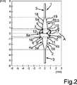
In
Wie in den Darstellungen in
Das einstückige optische Teil
In
Bei der Darstellung in
Im gezeigten Ausführungsbeispiel stellt die optische Seite
Das optisch abbildende Element
Das Teleskop
Wie zu erkennen ist, stellt das Teleskop
Wie darüber hinaus in
Darüber hinaus ist zu erkennen, dass der Radius
Im Ausführungsbeispiel ist auch vorgesehen, dass sich das Teleskop
Das Teleskop
In
In
Es kann auch vorgesehen sein, dass nur auf der Vorderseite
Insbesondere kann vorgesehen sein, dass die diffraktiven Strukturen
Bei der Darstellung in
In
Es kann auch vorgesehen sein, dass nur die Vorderseite
Durch diese Ausgestaltung werden monofokale Bereiche
ZITATE ENTHALTEN IN DER BESCHREIBUNG QUOTES INCLUDE IN THE DESCRIPTION
Diese Liste der vom Anmelder aufgeführten Dokumente wurde automatisiert erzeugt und ist ausschließlich zur besseren Information des Lesers aufgenommen. Die Liste ist nicht Bestandteil der deutschen Patent- bzw. Gebrauchsmusteranmeldung. Das DPMA übernimmt keinerlei Haftung für etwaige Fehler oder Auslassungen.This list of the documents listed by the applicant has been generated automatically and is included solely for the better information of the reader. The list is not part of the German patent or utility model application. The DPMA assumes no liability for any errors or omissions.
Zitierte PatentliteraturCited patent literature
- DE 69431428 T2[0004]DE 69431428 T2[0004]
- DE 112010004191 T5[0006]DE 112010004191 T5[0006]
- DE 69921648 T2[0007]DE 69921648 T2[0007]
Claims (10)
Translated fromGermanPriority Applications (6)
| Application Number | Priority Date | Filing Date | Title |
|---|---|---|---|
| DE102014119010.6ADE102014119010A1 (en) | 2014-12-18 | 2014-12-18 | Intraocular lens with integrated single-lens telescope integrated in the optical part |
| ES15813415TES2891304T3 (en) | 2014-12-18 | 2015-12-17 | Intraocular lens with a single-lens telescope integrated into the optics |
| PCT/EP2015/080314WO2016097192A1 (en) | 2014-12-18 | 2015-12-17 | Intraocular lens with single lens telescope integrated in the optical part thereof |
| CN201580068975.0ACN107205813B (en) | 2014-12-18 | 2015-12-17 | Intraocular lens with single lens telescope integrated in its optical portion |
| EP15813415.5AEP3232988B1 (en) | 2014-12-18 | 2015-12-17 | Intraocular lens with single lens telescope integrated in the optical part thereof |
| US15/625,419US10792148B2 (en) | 2014-12-18 | 2017-06-16 | Intraocular lens with single lens telescope integrated in the optical part thereof |
Applications Claiming Priority (1)
| Application Number | Priority Date | Filing Date | Title |
|---|---|---|---|
| DE102014119010.6ADE102014119010A1 (en) | 2014-12-18 | 2014-12-18 | Intraocular lens with integrated single-lens telescope integrated in the optical part |
Publications (1)
| Publication Number | Publication Date |
|---|---|
| DE102014119010A1true DE102014119010A1 (en) | 2016-06-23 |
Family
ID=54937076
Family Applications (1)
| Application Number | Title | Priority Date | Filing Date |
|---|---|---|---|
| DE102014119010.6AWithdrawnDE102014119010A1 (en) | 2014-12-18 | 2014-12-18 | Intraocular lens with integrated single-lens telescope integrated in the optical part |
Country Status (6)
| Country | Link |
|---|---|
| US (1) | US10792148B2 (en) |
| EP (1) | EP3232988B1 (en) |
| CN (1) | CN107205813B (en) |
| DE (1) | DE102014119010A1 (en) |
| ES (1) | ES2891304T3 (en) |
| WO (1) | WO2016097192A1 (en) |
Families Citing this family (2)
| Publication number | Priority date | Publication date | Assignee | Title |
|---|---|---|---|---|
| RU175238U1 (en)* | 2017-04-12 | 2017-11-28 | Сергей Николаевич Косарев | TELESCOPIC VOLUME-REPLACING INTRAOCULAR LENS |
| DE102019134178B3 (en)* | 2019-12-12 | 2020-12-31 | Carl Zeiss Meditec Ag | Intraocular lens with ropes or springs to deform the feel |
Citations (6)
| Publication number | Priority date | Publication date | Assignee | Title |
|---|---|---|---|---|
| FR1103399A (en)* | 1953-12-22 | 1955-11-02 | Microttica | Lenses intended for application in the anterior chamber of the eye |
| EP0897702A2 (en)* | 1997-06-26 | 1999-02-24 | Visioncare Ltd. | Intraocular lens implant |
| DE69431428T2 (en) | 1993-02-04 | 2003-06-18 | Visioncare Ophthalmic Technologies, Inc. | INTRAOCULAR USE FOR IMPLANTATION IN THE EYE |
| DE69921648T2 (en) | 1998-06-01 | 2005-11-10 | Visioncare Ophthalmic Technologies, Inc., Saratoga | INTRAOCULAR LENS WITH SWIVELED TUBE |
| DE112010004191T5 (en) | 2009-10-30 | 2012-11-22 | Akkolens International B.V. | Intraocular lenses for a variable focus |
| US8579970B1 (en)* | 2005-06-27 | 2013-11-12 | Visiogen, Inc. | Magnifying intraocular lens |
Family Cites Families (9)
| Publication number | Priority date | Publication date | Assignee | Title |
|---|---|---|---|---|
| US4666446A (en)* | 1986-05-06 | 1987-05-19 | Koziol Jeffrey E | Intraocular lens with converging and diverging optical portions |
| US5814103A (en)* | 1998-01-15 | 1998-09-29 | Visioncare Ltd. | Intraocular lens and telescope with mating fasteners |
| US6596026B1 (en)* | 2000-11-27 | 2003-07-22 | Visioncare Ophthalmic Technologies, Inc. | Telescopic intraocular lens |
| US7229475B2 (en)* | 2001-06-11 | 2007-06-12 | Vision Solutions Technologies, Inc. | Multi-focal intraocular lens, and methods for making and using same |
| US20040082995A1 (en)* | 2002-10-25 | 2004-04-29 | Randall Woods | Telescopic intraocular lens implant for treating age-related macular degeneration |
| US20050288784A1 (en)* | 2004-06-23 | 2005-12-29 | Peyman Gholam A | Bifocal intraocular telescope for low vision correction |
| US7186266B2 (en)* | 2003-06-06 | 2007-03-06 | Teledioptic Lens System, Llc | Bifocal intraocular telescope for low vision correction |
| US20070182917A1 (en)* | 2006-02-09 | 2007-08-09 | Alcon Manufacturing, Ltd. | Intra-ocular device with multiple focusing powers/optics |
| CA2770735C (en)* | 2009-08-13 | 2017-07-18 | Acufocus, Inc. | Masked intraocular implants and lenses |
- 2014
- 2014-12-18DEDE102014119010.6Apatent/DE102014119010A1/ennot_activeWithdrawn
- 2015
- 2015-12-17CNCN201580068975.0Apatent/CN107205813B/enactiveActive
- 2015-12-17ESES15813415Tpatent/ES2891304T3/enactiveActive
- 2015-12-17EPEP15813415.5Apatent/EP3232988B1/enactiveActive
- 2015-12-17WOPCT/EP2015/080314patent/WO2016097192A1/enactiveApplication Filing
- 2017
- 2017-06-16USUS15/625,419patent/US10792148B2/enactiveActive
Patent Citations (6)
| Publication number | Priority date | Publication date | Assignee | Title |
|---|---|---|---|---|
| FR1103399A (en)* | 1953-12-22 | 1955-11-02 | Microttica | Lenses intended for application in the anterior chamber of the eye |
| DE69431428T2 (en) | 1993-02-04 | 2003-06-18 | Visioncare Ophthalmic Technologies, Inc. | INTRAOCULAR USE FOR IMPLANTATION IN THE EYE |
| EP0897702A2 (en)* | 1997-06-26 | 1999-02-24 | Visioncare Ltd. | Intraocular lens implant |
| DE69921648T2 (en) | 1998-06-01 | 2005-11-10 | Visioncare Ophthalmic Technologies, Inc., Saratoga | INTRAOCULAR LENS WITH SWIVELED TUBE |
| US8579970B1 (en)* | 2005-06-27 | 2013-11-12 | Visiogen, Inc. | Magnifying intraocular lens |
| DE112010004191T5 (en) | 2009-10-30 | 2012-11-22 | Akkolens International B.V. | Intraocular lenses for a variable focus |
Also Published As
| Publication number | Publication date |
|---|---|
| EP3232988A1 (en) | 2017-10-25 |
| CN107205813A (en) | 2017-09-26 |
| CN107205813B (en) | 2019-12-17 |
| ES2891304T3 (en) | 2022-01-27 |
| US10792148B2 (en) | 2020-10-06 |
| EP3232988B1 (en) | 2021-07-28 |
| WO2016097192A1 (en) | 2016-06-23 |
| US20170281335A1 (en) | 2017-10-05 |
Similar Documents
| Publication | Publication Date | Title |
|---|---|---|
| DE69921648T2 (en) | INTRAOCULAR LENS WITH SWIVELED TUBE | |
| DE69708623T2 (en) | ONE-PIECE DEFORMABLE INTRAOCULAR LENS IMPLANT | |
| EP0742702B1 (en) | Intra-ocular lens arrangement for correcting astigmatism | |
| DE102010018436B4 (en) | Multifocal eye lens | |
| DE69426877T2 (en) | INTRAOCULAR LENS WITH DUAL 360 DEGREE HAPTICS | |
| DE69809697T2 (en) | INTRAOCULAR LENS | |
| DE69934917T2 (en) | LENS CONVERSION SYSTEM FOR TELEDIOPTIC OR BENDING OPTICAL CONFIGURATION | |
| DE60037902T2 (en) | INTRAOCULAR LENS SYSTEM | |
| DE69910991T2 (en) | ONE-PIECE DEFORMABLE INTRAOCULAR LENS IMPLANT | |
| DE102011114752A1 (en) | Lens with an extended focus area | |
| DE69132024T2 (en) | Multifocal intraocular implant | |
| DE112009001492T5 (en) | Accommodating intraocular lens | |
| DE60017132T2 (en) | INTRAOCULAR IMPLANT | |
| DE3249160T1 (en) | Intraocular lens for patients with central retinal degeneration | |
| DE102004025305A1 (en) | Accommodatable intraocular lens | |
| DE102007057122A1 (en) | Intraocular lens for implantation in eye, particularly human eye, has lens, which has optical axis, anterior optical surface that is transverse to optical axis, and posterior optical surface that is opposite to anterior optical surface | |
| DE202012013073U1 (en) | Ophthalmic lenses with enlarged optical glare zone | |
| DE69317487T2 (en) | Flexible intraocular lens implant | |
| DE69226959T2 (en) | HIGHLY MAGNIFYING TUBULAR GLASSES FOR AGE-RELATED MACULADEGENERATION | |
| EP1591080B1 (en) | Intraocular Lens | |
| EP3232988B1 (en) | Intraocular lens with single lens telescope integrated in the optical part thereof | |
| DE69918315T2 (en) | FRONT CHAMBER IMPLANT | |
| WO2008080464A1 (en) | Intraocular lens | |
| DE60109043T2 (en) | ROLLABLE INTRAOCULAR LENS | |
| DE69510671T2 (en) | INTRAOCULAR LENS FOR OPTIMAL ADAPTATION TO THE CAPSULE BAG |
Legal Events
| Date | Code | Title | Description |
|---|---|---|---|
| R012 | Request for examination validly filed | ||
| R016 | Response to examination communication | ||
| R119 | Application deemed withdrawn, or ip right lapsed, due to non-payment of renewal fee |