DE102014117175A1 - Pedicle screw system and spine stabilization system - Google Patents
Pedicle screw system and spine stabilization systemDownload PDFInfo
- Publication number
- DE102014117175A1 DE102014117175A1DE102014117175.6ADE102014117175ADE102014117175A1DE 102014117175 A1DE102014117175 A1DE 102014117175A1DE 102014117175 ADE102014117175 ADE 102014117175ADE 102014117175 A1DE102014117175 A1DE 102014117175A1
- Authority
- DE
- Germany
- Prior art keywords
- coupling
- pedicle screw
- bone
- screw system
- screw
- Prior art date
- Legal status (The legal status is an assumption and is not a legal conclusion. Google has not performed a legal analysis and makes no representation as to the accuracy of the status listed.)
- Withdrawn
Links
- 230000006641stabilisationEffects0.000titleclaimsabstractdescription20
- 238000011105stabilizationMethods0.000titleclaimsabstractdescription20
- 230000008878couplingEffects0.000claimsabstractdescription201
- 238000010168coupling processMethods0.000claimsabstractdescription201
- 238000005859coupling reactionMethods0.000claimsabstractdescription201
- 210000000988bone and boneAnatomy0.000claimsabstractdescription140
- 238000004873anchoringMethods0.000claimsdescription12
- 241000309551Arthraxon hispidusSpecies0.000description3
- 238000003780insertionMethods0.000description3
- 230000037431insertionEffects0.000description3
- 238000010276constructionMethods0.000description2
- 230000002349favourable effectEffects0.000description2
- 210000002414legAnatomy0.000description2
- BUHVIAUBTBOHAG-FOYDDCNASA-N(2r,3r,4s,5r)-2-[6-[[2-(3,5-dimethoxyphenyl)-2-(2-methylphenyl)ethyl]amino]purin-9-yl]-5-(hydroxymethyl)oxolane-3,4-diolChemical compoundCOC1=CC(OC)=CC(C(CNC=2C=3N=CN(C=3N=CN=2)[C@H]2[C@@H]([C@H](O)[C@@H](CO)O2)O)C=2C(=CC=CC=2)C)=C1BUHVIAUBTBOHAG-FOYDDCNASA-N0.000description1
- 241000722921Tulipa gesnerianaSpecies0.000description1
- 238000000149argon plasma sinteringMethods0.000description1
- 230000005540biological transmissionEffects0.000description1
- 230000015572biosynthetic processEffects0.000description1
- 230000000903blocking effectEffects0.000description1
- 238000005520cutting processMethods0.000description1
- 238000005553drillingMethods0.000description1
- 238000003384imaging methodMethods0.000description1
- 238000002513implantationMethods0.000description1
- 238000004519manufacturing processMethods0.000description1
- 238000000034methodMethods0.000description1
- 238000003801millingMethods0.000description1
- 238000005457optimizationMethods0.000description1
- 238000010079rubber tappingMethods0.000description1
- 238000007493shaping processMethods0.000description1
- 210000000689upper legAnatomy0.000description1
Images


Classifications
- A—HUMAN NECESSITIES
- A61—MEDICAL OR VETERINARY SCIENCE; HYGIENE
- A61B—DIAGNOSIS; SURGERY; IDENTIFICATION
- A61B17/00—Surgical instruments, devices or methods
- A61B17/56—Surgical instruments or methods for treatment of bones or joints; Devices specially adapted therefor
- A61B17/58—Surgical instruments or methods for treatment of bones or joints; Devices specially adapted therefor for osteosynthesis, e.g. bone plates, screws or setting implements
- A61B17/68—Internal fixation devices, including fasteners and spinal fixators, even if a part thereof projects from the skin
- A61B17/70—Spinal positioners or stabilisers, e.g. stabilisers comprising fluid filler in an implant
- A61B17/7001—Screws or hooks combined with longitudinal elements which do not contact vertebrae
- A61B17/7035—Screws or hooks, wherein a rod-clamping part and a bone-anchoring part can pivot relative to each other
- A61B17/7037—Screws or hooks, wherein a rod-clamping part and a bone-anchoring part can pivot relative to each other wherein pivoting is blocked when the rod is clamped
- A—HUMAN NECESSITIES
- A61—MEDICAL OR VETERINARY SCIENCE; HYGIENE
- A61B—DIAGNOSIS; SURGERY; IDENTIFICATION
- A61B17/00—Surgical instruments, devices or methods
- A61B17/56—Surgical instruments or methods for treatment of bones or joints; Devices specially adapted therefor
- A61B17/58—Surgical instruments or methods for treatment of bones or joints; Devices specially adapted therefor for osteosynthesis, e.g. bone plates, screws or setting implements
- A61B17/68—Internal fixation devices, including fasteners and spinal fixators, even if a part thereof projects from the skin
- A61B17/70—Spinal positioners or stabilisers, e.g. stabilisers comprising fluid filler in an implant
- A61B17/7001—Screws or hooks combined with longitudinal elements which do not contact vertebrae
- A61B17/7032—Screws or hooks with U-shaped head or back through which longitudinal rods pass
- A—HUMAN NECESSITIES
- A61—MEDICAL OR VETERINARY SCIENCE; HYGIENE
- A61B—DIAGNOSIS; SURGERY; IDENTIFICATION
- A61B17/00—Surgical instruments, devices or methods
- A61B17/56—Surgical instruments or methods for treatment of bones or joints; Devices specially adapted therefor
- A61B17/58—Surgical instruments or methods for treatment of bones or joints; Devices specially adapted therefor for osteosynthesis, e.g. bone plates, screws or setting implements
- A61B17/68—Internal fixation devices, including fasteners and spinal fixators, even if a part thereof projects from the skin
- A61B17/70—Spinal positioners or stabilisers, e.g. stabilisers comprising fluid filler in an implant
- A61B17/7001—Screws or hooks combined with longitudinal elements which do not contact vertebrae
- A61B17/7035—Screws or hooks, wherein a rod-clamping part and a bone-anchoring part can pivot relative to each other
- A61B17/704—Screws or hooks, wherein a rod-clamping part and a bone-anchoring part can pivot relative to each other the longitudinal element passing through a ball-joint in the screw head
- A—HUMAN NECESSITIES
- A61—MEDICAL OR VETERINARY SCIENCE; HYGIENE
- A61B—DIAGNOSIS; SURGERY; IDENTIFICATION
- A61B17/00—Surgical instruments, devices or methods
- A61B17/56—Surgical instruments or methods for treatment of bones or joints; Devices specially adapted therefor
- A61B17/58—Surgical instruments or methods for treatment of bones or joints; Devices specially adapted therefor for osteosynthesis, e.g. bone plates, screws or setting implements
- A61B17/68—Internal fixation devices, including fasteners and spinal fixators, even if a part thereof projects from the skin
- A61B17/70—Spinal positioners or stabilisers, e.g. stabilisers comprising fluid filler in an implant
- A61B17/7001—Screws or hooks combined with longitudinal elements which do not contact vertebrae
- A61B17/7044—Screws or hooks combined with longitudinal elements which do not contact vertebrae also having plates, staples or washers bearing on the vertebrae
- A—HUMAN NECESSITIES
- A61—MEDICAL OR VETERINARY SCIENCE; HYGIENE
- A61B—DIAGNOSIS; SURGERY; IDENTIFICATION
- A61B17/00—Surgical instruments, devices or methods
- A61B17/56—Surgical instruments or methods for treatment of bones or joints; Devices specially adapted therefor
- A61B17/58—Surgical instruments or methods for treatment of bones or joints; Devices specially adapted therefor for osteosynthesis, e.g. bone plates, screws or setting implements
- A61B17/68—Internal fixation devices, including fasteners and spinal fixators, even if a part thereof projects from the skin
- A61B17/70—Spinal positioners or stabilisers, e.g. stabilisers comprising fluid filler in an implant
- A61B17/7074—Tools specially adapted for spinal fixation operations other than for bone removal or filler handling
- A61B17/7076—Tools specially adapted for spinal fixation operations other than for bone removal or filler handling for driving, positioning or assembling spinal clamps or bone anchors specially adapted for spinal fixation
- A61B17/7077—Tools specially adapted for spinal fixation operations other than for bone removal or filler handling for driving, positioning or assembling spinal clamps or bone anchors specially adapted for spinal fixation for moving bone anchors attached to vertebrae, thereby displacing the vertebrae
Landscapes
- Health & Medical Sciences (AREA)
- Orthopedic Medicine & Surgery (AREA)
- Neurology (AREA)
- Life Sciences & Earth Sciences (AREA)
- Surgery (AREA)
- Heart & Thoracic Surgery (AREA)
- Engineering & Computer Science (AREA)
- Biomedical Technology (AREA)
- Nuclear Medicine, Radiotherapy & Molecular Imaging (AREA)
- Medical Informatics (AREA)
- Molecular Biology (AREA)
- Animal Behavior & Ethology (AREA)
- General Health & Medical Sciences (AREA)
- Public Health (AREA)
- Veterinary Medicine (AREA)
- Surgical Instruments (AREA)
Abstract
Translated fromGermanDescription
Translated fromGermanDie vorliegende Erfindung betrifft ein Pedikelschraubensystem umfassend eine Pedikelschraube mit einem Schraubenschaft, welcher ein Außengewinde aufweist, und einem kugelgelenkig am Schraubenschaft gelagerten Schraubenkopf, welcher Schraubenkopf eine Verbindungselementaufnahme für ein Verbindungselement eines Wirbelsäulenstabilisierungssystems umfasst.The present invention relates to a pedicle screw system comprising a pedicle screw with a screw shaft which has an external thread, and a ball head mounted on the screw shaft screw head, which screw head comprises a connection element receptacle for a connecting element of a spine stabilization system.
Die Erfindung betrifft ferner ein Wirbelsäulenstabilisierungssystem umfassend mindestens zwei Knochenschrauben und mindestens ein an den mindestens zwei Knochenschrauben festlegbares Verbindungselement.The invention further relates to a spine stabilization system comprising at least two bone screws and at least one fixable to the at least two bone screws connecting element.
Pedikelschrauben und Wirbelsäulenstabilisierungssysteme der eingangs beschriebenen Art sind beispielsweise aus der
Bei Pedikelschraubensystemen, bei denen ein Verbindungselement von oben in eine entsprechende Verbindungselementaufnahme am Schraubenkopf eingesetzt werden kann, also bei sogenannten "Tulpen"-Systemen, ist eine Krafteinleitung nicht möglich, wenn die Pedikelschraube in Form einer Polyaxialschraube ausgebildet ist. Eine Krafteinleitung ist nur möglich, wenn der Schraubenkopf relativ zum Schraubenschaft unbeweglich oder maximal um eine Achse verschwenkbar ist, es sich also bei der Pedikelschraube um eine sogenannte Monoaxialschraube handelt. Der Schraubenkopf wird dabei in einer Ebene bewegt, welche senkrecht zur Achse, um die verschwenkt wird, verläuft, so dass die Monoaxialschraube in diesem Sinne auch als Uniplanarschraube bezeichnet werden kann. Bei Polyaxialschrauben hingegen, die das Einsetzen des Verbindungselements, beispielsweise eines Stabs, deutlich dadurch vereinfachen, dass der Schraubenkopf beliebig relativ zum Schraubenschaft orientiert werden kann, ist eine solche Krafteinleitung und Korrektur einer Ausrichtung eines Wirbels nicht oder nur rudimentär möglich. Insbesondere ist es nicht möglich, die Technik der segmentalen Derotation bei Polyaxialschrauben anzuwenden. Diese ist nur bei direkter Krafteinleitung in die Pedikelschraube, wie es insbesondere die beschriebenen Monoaxialschrauben ermöglichen, realisierbar.In pedicle screw systems in which a connecting element can be inserted from above into a corresponding connecting element receptacle on the screw head, that is in so-called "tulip" systems, a force introduction is not possible if the pedicle screw is designed in the form of a polyaxial screw. An introduction of force is only possible if the screw head is immovable relative to the screw shaft or at most pivotable about an axis, so it is in the pedicle screw is a so-called monoaxial screw. The screw head is thereby moved in a plane which is perpendicular to the axis about which is pivoted, runs, so that the monoaxial screw can be referred to in this sense as a uniplanar screw. In contrast, in polyaxial screws, which simplify the insertion of the connecting element, such as a rod, significantly by the fact that the screw head can be arbitrarily oriented relative to the screw shaft, such force application and correction of alignment of a vortex is not or only possible rudimentary. In particular, it is not possible to apply the technique of segmental derotation in polyaxial screws. This can only be achieved with a direct introduction of force into the pedicle screw, as is possible in particular by the monoaxial screws described.
Es ist daher eine Aufgabe der vorliegenden Erfindung, ein Pedikelschraubensystem und ein Wirbelsäulenstabilisierungssystem der eingangs beschriebenen Art so weiter zu bilden, dass deren Handhabung verbessert wird.It is therefore an object of the present invention to further develop a pedicle screw system and a spinal stabilization system of the type described in the opening paragraph so that their handling is improved.
Diese Aufgabe wird bei einem Pedikelschraubensystem der eingangs beschriebenen Art erfindungsgemäß dadurch gelöst, dass es eine Knochenausrichteinrichtung und eine Kopplungseinrichtung umfasst zum kraft- und/oder formschlüssigen Koppeln der Knochenausrichteinrichtung und des Schraubenschafts in einer Ausrichtstellung.This object is achieved in a pedicle screw system of the type described above according to the invention in that it comprises a Knochenausrichteinrichtung and a coupling device for non-positive and / or positive coupling of the bone alignment and the screw shaft in an alignment position.
Die erfindungsgemäß vorgeschlagene Weiterbildung ermöglicht es dem Operateur insbesondere, über die Knochenausrichteinrichtung Kräfte zum Bewegen, insbesondere Rotieren, deformierter Wirbel einer Wirbelsäule direkt auf den Schraubenschaft einzuleiten, wenn die Kopplungseinrichtung des Pedikelschraubensystems die Ausrichtstellung einnimmt. Das vorgeschlagene Pedikelschraubensystem vereinigt somit einerseits die Vorteile von Polyaxialschrauben, die eine beliebige Ausrichtung des Schraubenkopfs relativ zum Schraubenschaft ermöglichen, um das Einsetzen des Verbindungselements in die Verbindungselementaufnahme am Schraubenkopf zu erleichtern, und andererseits die Vorteile von starren Schrauben oder Monoaxialschrauben, die das Einleiten von Kräften auf den Schraubenschaft zur Ausrichtung eines Wirbelkörpers, in den die Pedikelschraube eingeschraubt ist, ermöglichen. Durch die Kopplungseinrichtung können insbesondere eine axiale und/oder drehfeste Verbindung zwischen der Knochenausrichteinrichtung und dem Schraubenschaft hergestellt und somit über die Knochenausrichteinrichtung eine indirekte Kraftübertragung beispielsweise von einem Ausrichtinstrument auf den Schraubenschaft ermöglicht werden.The development proposed according to the invention makes it possible for the surgeon, in particular, to initiate forces for moving, in particular rotating, deformed vertebrae of a spinal column directly onto the screw shaft via the bone alignment device, when the coupling device of the pedicle screw system assumes the alignment position. The proposed pedicle screw system thus combines, on the one hand, the advantages of polyaxial screws which allow any alignment of the screw head relative to the screw shaft to facilitate insertion of the connector into the connector receptacle on the screw head and, on the other hand, the advantages of rigid screws or monoaxial screws which induce forces on the screw shaft for alignment of a vertebral body, in which the pedicle screw is screwed allow. In particular, an axial and / or rotationally fixed connection between the bone alignment device and the screw shaft can be produced by the coupling device and thus an indirect force transmission, for example from an alignment instrument, to the screw shaft can be made possible via the bone alignment device.
Besonders einfach und kostengünstig ausbilden lässt sich das Pedikelschraubensystem, wenn die Knochenausrichteinrichtung in Form einer Knochenplatte ausgebildet ist. Insbesondere kann die Knochenplatte eine Knochenanlagefläche aufweisen, die eine möglichst flächige Anlage an einen Knochen ermöglicht. Insbesondere kann sie an entsprechend einer anatomischen Krümmung des Knochens, an den sie angelegt werden soll, geformt oder an diese angepasst sein. Beispielsweise kann eine patientenindividuelle Krümmung der Knochenplatte auf Basis von Patientendaten, insbesondere CT-Daten oder andere, durch bildgebende Verfahren ermittelten Daten, hergestellt werden. Zur Ausbildung der insbesondere patientenindividuellen Knochenplatte können zum Beispiel spanende, insbesondere Fräsen, oder generative Herstellungsverfahren, insbesondere Lasersintern, zur Anwendung kommen.The pedicle screw system can be designed in a particularly simple and cost-effective manner if the bone alignment device is designed in the form of a bone plate. In particular, the bone plate may have a bone abutment surface, which allows the largest possible contact with a bone. In particular, it may be shaped or adapted to correspond to an anatomical curvature of the bone to which it is to be applied. For example, a patient-specific curvature of the bone plate can be produced on the basis of patient data, in particular CT data or other data determined by means of imaging methods. For example, cutting, in particular milling, or generative production methods, in particular laser sintering, can be used to form the bone plate, which in particular is patient-specific.
Um eine Rotation der Knochenausrichteinrichtung am Knochen, an dem sie anliegt, zu verhindern oder die Gefahr hierfür zu reduzieren, ist es vorteilhaft, wenn die Knochenausrichteinrichtung mindestens ein Knochenverankerungselement trägt oder umfasst.It is to prevent or reduce the risk of rotation of the bone alignment device on the bone against which it abuts advantageous if the bone alignment device carries or comprises at least one bone anchoring element.
Günstigerweise ist das mindestens eine Knochenverankerungselement in Form eines Knochenpins oder eines Knochenzahns ausgebildet. Diese können insbesondere von der in Form einer Knochenplatte ausgebildeten Knochenausrichteinrichtung abstehend ausgebildet sein.Conveniently, the at least one bone anchoring element is designed in the form of a bone pin or a bone tooth. These may be designed in particular projecting from the formed in the form of a bone plate bone alignment.
Um eine besonders stabile Knochenausrichteinrichtung zu erhalten, ist es günstig, wenn das mindestens eine einstückig mit der Knochenausrichteinrichtung ausgebildet ist.In order to obtain a particularly stable bone alignment device, it is favorable if the at least one is formed integrally with the bone alignment device.
Gemäß einer weiteren bevorzugten Ausführungsform der Erfindung kann vorgesehen sein, dass die Kopplungseinrichtung erste und zweite Kopplungselemente umfasst, welche in der Ausrichtstellung kraft- und/oder formschlüssig in Eingriff stehen und einerseits an der Knochenausrichteinrichtung und andererseits am Schraubenschaft angeordnet oder ausgebildet sind. Mit einer derart ausgebildeten Kopplungseinrichtung ist es auf einfache Weise möglich, eine axiale und/oder drehfeste Verbindung zwischen der Knochenausrichteinrichtung und dem Schraubenschaft herzustellen, insbesondere in der Ausrichtstellung. Bevor das Pedikelschraubensystem die Ausrichtstellung einnimmt, können die ersten und zweiten Kopplungselemente in Abhängigkeit von ihrer konkreten Ausgestaltung beispielsweise gegeneinander rotiert werden, insbesondere polyaxial durch Ausbildung eines Kugelgelenks zwischen dem ersten und zweiten Kopplungselement, um dann in ihrer Bewegungsfreiheit relativ zueinander ganz oder teilweise eingeschränkt zu werden. Beispielsweise können die ein Kugelgelenk ausbildenden ersten und zweiten Kopplungselemente bei vollständig oder nahezu vollständig in den Knochen eingeschraubter Pedikelschraube gegeneinander gepresst oder aktiv durch ein zusätzliches Blockierelement relativ zueinander blockiert werden.According to a further preferred embodiment of the invention, it can be provided that the coupling device comprises first and second coupling elements, which are non-positively and / or positively engaged in the alignment position and arranged or formed on the bone alignment device and on the screw shaft on the one hand. With such a coupling device, it is possible in a simple manner to produce an axial and / or rotationally fixed connection between the bone alignment device and the screw shaft, in particular in the alignment position. Before the pedicle screw system assumes the alignment position, the first and second coupling elements can, for example, be rotated against each other depending on their specific configuration, in particular polyaxially by forming a ball joint between the first and second coupling element, in order then to be completely or partially restricted in their freedom of movement relative to each other , For example, the first and second coupling elements forming a ball joint can be pressed against one another or actively blocked by an additional blocking element relative to one another when the pedicle screw is fully or almost completely screwed into the bone.
Vorteilhaft ist es, wenn das erste Kopplungselement in Form eines Kopplungsvorsprungs und dass das zweite Kopplungselement in Form einer zum Kopplungsvorsprung korrespondierenden Kopplungsaufnahme ausgebildet ist. Beispielsweise kann der Kopplungsvorsprung an der Knochenausrichteinrichtung oder am Schraubenschaft ausgebildet sein. Entsprechend kann korrespondierend die Kopplungsaufnahme am Schraubenschaft oder an der Knochenausrichteinrichtung ausgebildet sein.It is advantageous if the first coupling element in the form of a coupling projection and that the second coupling element is designed in the form of a coupling projection corresponding to the coupling projection. For example, the coupling projection may be formed on the bone alignment device or on the screw shaft. Correspondingly, the coupling receptacle can correspondingly be formed on the screw shaft or on the bone alignment device.
Eine axiale und/oder eine drehfeste Verbindung zwischen der Knochenausrichteinrichtung und dem Schraubenschaft lässt sich auf einfache Weise dadurch realisieren, dass der Kopplungsvorsprung in der Ausrichtstellung formschlüssig oder im Wesentlichen formschlüssig in die Kopplungsaufnahme eingreift.An axial and / or rotationally fixed connection between the bone alignment device and the screw shaft can be realized in a simple manner by virtue of the coupling projection in the alignment position engaging in the coupling receptacle in a form-fitting or substantially positive-locking manner.
Vorzugsweise ist der Kopplungsvorsprung einstückig mit dem Schraubenschaft ausgebildet oder kraft- und/oder stoffschlüssig mit dem Schraubenschaft verbunden. Beispielsweise kann der Kopplungsvorsprung mit dem Schraubenschaft verpresst, verklebt, verlötet oder verschweißt sein. Insbesondere ermöglicht es der Kopplungsvorsprung, Kräfte von der Knochenausrichteinrichtung über den Kopplungsvorsprung auf den Schraubenschaft einzuleiten.Preferably, the coupling projection is integrally formed with the screw shaft or non-positively and / or materially connected to the screw shaft. For example, the coupling projection can be pressed, glued, soldered or welded to the screw shaft. In particular, the coupling projection allows forces from the bone alignment device to be introduced to the screw shaft via the coupling projection.
Auf besonders einfache und kostengünstige Weise herstellen lässt sich das Pedikelschraubensystem, wenn der Kopplungsvorsprung in Form eines Ringflansches ausgebildet ist. Beispielsweise kann dieser einstückig mit dem Schraubenschaft ausgebildet sein.The pedicle screw system can be produced in a particularly simple and cost-effective manner if the coupling projection is designed in the form of an annular flange. For example, this may be formed integrally with the screw shaft.
Für die Ausbildung einer Polyaxialschraube ist es günstig, wenn der Schraubenschaft einen Gelenkkopf aufweist und wenn der Schraubenkopf eine zum Gelenkkopf korrespondierende Gelenkkopfaufnahme zur Ausbildung eines Kugelgelenks im Zusammenwirken mit dem Gelenkkopf aufweist. Diese Ausgestaltung ermöglicht es insbesondere, den Schraubenkopf um einen Mittelpunkt eines beispielsweise kugelförmigen Gelenkkopfs relativ zum Schraubenschaft zu rotieren und auszurichten.For the formation of a polyaxial screw, it is advantageous if the screw shaft has a condyle and if the screw head has a condyle head corresponding to the condyle to form a ball joint in cooperation with the condyle. This embodiment makes it possible, in particular, to rotate and align the screw head about a center point of, for example, a spherical condyle relative to the screw shaft.
Um einen möglichst kompakten Aufbau der Pedikelschraube zu ermöglichen, ist es vorteilhaft, wenn der Kopplungsvorsprung zwischen dem Außengewinde und dem Gelenkkopf angeordnet ist.In order to allow the most compact construction of the pedicle screw, it is advantageous if the coupling projection between the external thread and the condyle is arranged.
Vorzugsweise ist ein Außendurchmesser des Kopplungsvorsprungs größer ist als ein maximaler Außendurchmesser des Außengewindes. Dies ermöglicht es insbesondere, den Kopplungsvorsprung auch als Anschlagelement zu nutzen, um eine definierte Kopplung zwischen dem Schraubenschaft und der Knochenausrichteinrichtung zu erreichen.Preferably, an outer diameter of the coupling projection is larger than a maximum outer diameter of the external thread. This makes it possible, in particular, to use the coupling projection as a stop element in order to achieve a defined coupling between the screw shaft and the bone alignment device.
Günstigerweise grenzt der Kopplungsvorsprung direkt an das Außengewinde an. Auf diese Weise kann insbesondere erreicht werden, dass der Schraubenschaft auch ohne Verwendung der Knochenausrichteinrichtung bis zum Kopplungsvorsprung in einen Knochen eingeschraubt werden kann.Conveniently, the coupling projection directly adjoins the external thread. In this way it can be achieved, in particular, that the screw shaft can be screwed into a bone even without using the bone alignment device as far as the coupling projection.
Vorteilhaft ist es, wenn die Kopplungsaufnahme in Form einer Ausnehmung der Knochenausrichteinrichtung ausgebildet ist. So kann der Kopplungsvorsprung des Schraubenschafts auf einfache Weise in die Kopplungsaufnahme eingreifen.It is advantageous if the coupling receptacle is designed in the form of a recess of the bone alignment device. Thus, the coupling projection of the screw shaft can engage in a simple manner in the coupling receptacle.
Ferner kann vorgesehen sein, dass die Knochenausrichteinrichtung eine Schraubenschaftaufnahme aufweist, in die der Schraubenschaft in der Ausrichtstellung mindestens teilweise eingreift. Beispielsweise kann der Schraubenschaft die Schraubenschaftaufnahme in der Ausrichtstellung auch durchsetzen. So kann eine zusätzliche Optimierung der Kopplung zwischen der Knochenausrichteinrichtung und dem Schraubenschaft erreicht werden. Furthermore, it can be provided that the bone alignment device has a screw shaft receptacle, in which the screw shaft engages at least partially in the alignment position. For example, the screw shaft can also penetrate the screw shaft receptacle in the alignment position. Thus, an additional optimization of the coupling between the bone alignment device and the screw shaft can be achieved.
Um den Schraubenschaft in die Schraubenschaftaufnahme auf einfache Weise einführen zu können, ist es günstig, wenn die Schraubenschaftaufnahme in Form einer Durchbrechung der Knochenausrichteinrichtung ausgebildet ist. Beispielsweise kann die Durchbrechung in Form einer Bohrung ausgebildet sein. Alternativ ist es auch möglich, die Schraubenschaftaufnahme mit einem Querschnitt auszubilden, welcher eine N-zählige Symmetrie aufweist. So kann insbesondere auf einfache Weise eine drehfeste Kopplung zwischen der Knochenausrichteinrichtung und dem Schraubenschaft hergestellt werden.In order to be able to introduce the screw shaft into the screw shaft receptacle in a simple manner, it is expedient for the screw shaft receptacle to be in the form of an opening in the bone alignment device. For example, the opening may be formed in the form of a bore. Alternatively, it is also possible to form the screw shank receptacle with a cross section which has an N-fold symmetry. In particular, a rotationally fixed coupling between the bone alignment device and the screw shaft can be produced in a simple manner.
Für einen möglichst kompakten Aufbau der Pedikelschraube ist es günstig, wenn die Kopplungsaufnahme direkt an die Schraubenschaftaufnahme angrenzt. Durch entsprechende Formgebung der Kopplungsaufnahme und der Schraubenschaftaufnahme können so auf einfache Weise sowohl eine axiale Fixierung als auch eine drehfeste Verbindung in Umfangsrichtung hergestellt werden.For a very compact construction of the pedicle screw, it is advantageous if the coupling receptacle directly adjacent to the screw shank receptacle. By appropriate shaping of the coupling receptacle and the screw shank receiving both axial fixation and a rotationally fixed connection in the circumferential direction can be prepared in a simple manner.
Vorzugsweise weist die Kopplungsaufnahme einen größeren Innendurchmesser auf als die Schraubenschaftaufnahme. Auf diese Weise kann die Schraubenschaftaufnahme einen Anschlag für den Kopplungsvorsprung bilden, wenn dieser in die Kopplungsaufnahme eingreift.Preferably, the coupling receptacle has a larger inner diameter than the screw shaft receptacle. In this way, the screw shaft receptacle can form a stop for the coupling projection when it engages in the coupling receptacle.
Gemäß einer weiteren bevorzugten Ausführungsform der Erfindung kann vorgesehen sein, dass die Kopplungseinrichtung eine Längsachse definiert, welche parallel zu einer Schraubenschaftlängsachse des Schraubenschafts verläuft oder mit dieser einen Neigungswinkel einschließt. Beispielsweise kann die Knochenausrichteinrichtung in Form einer Knochenplatte ausgebildet sein, die eine Ebene definiert. Bezogen auf diese kann dann eine Kopplung zwischen Knochenausrichteinrichtung und dem Schraubenschaft erreicht werden, bei der die Schraubenschaftlängsachse senkrecht zu der von der Knochenplatte definierten Ebene ausgerichtet oder relativ zu dieser geneigt ist. Abhängig von der Form eines Wirbels können beispielsweise unterschiedlich ausgebildete Knochenausrichteinrichtungen in Form eines Satzes von Knochenausrichteinrichtungen bereitgestellt werden, um einem Operateur eine optimale Auswahl zu bieten, um die für den Patienten bestmögliche Knochenausrichteinrichtung zu wählen, damit er die deformierte Wirbelsäule wieder in eine gewünschte Form bringen kann.According to a further preferred embodiment of the invention, it can be provided that the coupling device defines a longitudinal axis which extends parallel to a screw shaft longitudinal axis of the screw shaft or includes an inclination angle therewith. For example, the bone alignment device may be in the form of a bone plate defining a plane. Based on these, a coupling between bone alignment device and the screw shaft can then be achieved, in which the screw shaft longitudinal axis is aligned perpendicular to the plane defined by the bone plate or inclined relative thereto. For example, depending on the shape of a vertebra, differently configured bone alignment devices may be provided in the form of a set of bone alignment devices to provide a surgeon with optimal choice to select the best possible bone alignment device for the patient to restore the deformed spine to a desired shape can.
Um beispielsweise mit einem Ausrichtrinstrument einen Wirbel mit daran festgeschraubter Pedikelschraube auf einfache Weise ausrichten zu können, ist es günstig, wenn die Knochenausrichteinrichtung mindestens eine Kupplungseinrichtung zum temporären kraft- und/oder formschlüssigen Kuppeln mit einem Ausrichtinstrument in einer Kuppelstellung aufweist. Die Kupplungseinrichtung ermöglicht es also einem Operateur, bei Bedarf ein Ausrichtinstrument mit der Knochenausrichteinrichtung in Eingriff zu bringen und so mit dem Ausrichtinstrument eine Kraft zum Ausrichten des Wirbelkörpers über die Knochenausrichteinrichtung auf den Schraubenschaft und somit auf den Wirbel zu übertragen.In order to be able to align a vertebra with the pedicle screw screwed thereto in an easy manner, for example, with an alignment instrument, it is favorable if the bone alignment device has at least one coupling device for temporary non-positive and / or positive coupling with an alignment instrument in a coupling position. The coupling device thus makes it possible for a surgeon, if necessary, to bring an alignment instrument into engagement with the bone alignment device and thus to transmit with the alignment instrument a force for aligning the vertebral body via the bone alignment device to the screw shaft and thus to the vertebra.
Um ein einfaches Kuppeln mit unterschiedlichsten Ausrichtinstrumenten zu ermöglichen, ist es günstig, wenn das mindestens eine Kupplungselement in Form eines Kupplungsvorsprungs und/oder in Form einer Kupplungsausnehmung ausgebildet ist. Dies bedeutet insbesondere auch, dass das mindestens eine Kupplungselement teilweise als Kupplungsvorsprungs und teileweise Kupplungsausnehmung ausgebildet sein kann. Beispielsweise kann ein Ausrichtinstrument mit einem freien Ende in eine Kupplungsausnehmung eingreifen oder mit einer Ausnehmung am freien Ende einen Kupplungsvorsprung an der Knochenausrichteinrichtung aufnehmen, um vorzugsweise eine axiale und/oder drehfeste Kupplung zwischen dem Ausrichtinstrument und der Knochenausrichteinrichtung zu erreichen.In order to enable a simple coupling with a wide variety of alignment, it is advantageous if the at least one coupling element in the form of a coupling projection and / or in the form of a coupling recess is formed. This means in particular that the at least one coupling element can be partially formed as a coupling projection and partially coupling recess. For example, an alignment tool may engage a free end in a coupling recess or receive a coupling projection on the bone alignment device with a recess at the free end to preferably achieve an axial and / or rotationally fixed coupling between the alignment instrument and the bone alignment device.
Auf besonders einfache Weise herstellen lässt sich die Kupplungseinrichtung, wenn die Kupplungsausnehmung in Form eines Sacklochs oder einer Durchbrechung ausgebildet ist. Insbesondere kann die Durchbrechung in Form einer Bohrung ausgebildet sein.The coupling device can be produced in a particularly simple manner if the coupling recess is designed in the form of a blind hole or an opening. In particular, the opening may be formed in the form of a bore.
Um eine definierte Verbindung zwischen der Knochenausrichteinrichtung und einem Ausrichtinstrument zu ermöglichen, ist es vorteilhaft, wenn das mindestens eine Kupplungselement ein Gewinde umfasst oder in Form eines Rastelements ausgebildet ist. Beispielsweise kann das Gewinde in Form eines Außen- oder in Form eines Innengewindes ausgebildet sein. Das Ausrichtinstrument kann so auf einfache Weise mit der Knochenausrichteinrichtung verschraubt werden. Eine einfache Form der Verbindung wird erreicht, wenn das Kupplungselement in Form Rastelements ausgebildet ist, sodass auf einfache Weise ein Verrasten zwischen dem Ausrichtinstrument und der Knochenausrichteinrichtung möglich ist, um diese axial und/oder drehfest miteinander zu kuppeln.In order to enable a defined connection between the bone alignment device and an alignment instrument, it is advantageous if the at least one coupling element comprises a thread or is designed in the form of a latching element. For example, the thread may be in the form of an external or in the form of an internal thread. The alignment instrument can thus be easily screwed to the bone alignment device. A simple form of the connection is achieved when the coupling element is designed in the form of latching element, so that in a simple manner, a locking between the alignment and the bone alignment is possible to couple these axially and / or rotationally fixed to each other.
Vorteilhafterweise umfasst das Pedikelschraubensystem ein Ausrichtinstrument zum temporären kraft- und/oder formschlüssigen Kuppeln mit der Kupplungseinrichtung. Mit dem Ausrichtinstrument kann in der beschriebenen Weise eine Kraft zum Ausrichten eines Wirbels über die Knochenausrichteinrichtung auf den Schraubenschaft ausgeübt werden. Advantageously, the pedicle screw system comprises an alignment instrument for temporary non-positive and / or positive coupling with the coupling device. With the alignment instrument, a force for aligning a vertebra can be exerted on the screw shaft via the bone alignment device as described.
Vorzugsweise weist das Ausrichtinstrument distalseitig ein Kupplungsende auf zum kraft- und/oder formschlüssigen Kuppeln mit der Kupplungseinrichtung. Ein derart ausgebildetes Kupplungsende ermöglicht es insbesondere auf einfache und sicherere Weise, das Ausrichtinstrument beispielsweise axial und/oder drehfest mit der Knochenausrichteinrichtung zu kuppeln.The alignment instrument preferably has a coupling end on the distal side for non-positive and / or positive coupling with the coupling device. Such a trained coupling end makes it possible in particular in a simple and safer way, for example, axially and / or rotationally fixed to couple the alignment with the bone alignment device.
Gemäß einer besonders bevorzugten Ausführungsform der Erfindung kann vorgesehen sein, dass das Kupplungsende in Form eines Rastelements ausgebildet ist oder ein Gewinde umfasst, welches korrespondierend zum Gewinde des mindestens einen Kupplungselements ausgebildet ist. Das Kupplungsende in Form Rastelements kann auf einfache Weise mit einem korrespondierend ausgebildeten Rastelement an der Knochenausrichteinrichtung rastend in Eingriff gebracht werden, um eine axiale und/oder drehfeste Verbindung schnell und einfach herzustellen. Alternativ kann das ein Gewinde aufweisendes Kupplungsende auch mit dem Gewinde des mindestens einen Kupplungselements verschraubt werden.According to a particularly preferred embodiment of the invention can be provided that the coupling end is formed in the form of a latching element or comprises a thread which is formed corresponding to the thread of the at least one coupling element. The coupling end in the form of latching element can be easily brought into engagement with a correspondingly formed latching element on the bone alignment device in order to produce an axial and / or non-rotatable connection quickly and easily. Alternatively, the threaded end having a coupling end can also be screwed to the thread of the at least one coupling element.
Die eingangs gestellte Aufgabe wird ferner bei einem Wirbelsäulenstabilisierungssystem der eingangs beschriebenen Art erfindungsgemäß dadurch gelöst, dass mindestens eine der mindestens zwei Knochenschrauben in Form eines der oben beschriebenen Pedikelschraubensysteme ausgebildet ist.The object stated in the introduction is also achieved according to the invention in a spine stabilization system of the type described in the opening paragraph in that at least one of the at least two bone screws is designed in the form of one of the above-described pedicle screw systems.
Ein derart weitergebildetes Wirbelsäulenstabilisierungssystem weist dann insbesondere auch die oben im Zusammenhang mit bevorzugten Ausführungsformen von Pedikelschraubensystemen beschriebenen Vorteile auf.A spinal stabilization system developed in this way then also has, in particular, the advantages described above in connection with preferred embodiments of pedicle screw systems.
Die vorstehende Beschreibung umfasst somit insbesondere die nachfolgend in Form durchnummerierter Sätze definierten Ausführungsformen von Pedikelschraubensystemen und Wirbelsäulenstabilisierungssystemen:
- 1. Pedikelschraubensystem (
20 ) umfassend eine Pedikelschraube (24 ) mit einem Schraubenschaft (26 ), welcher ein Außengewinde (28 ) aufweist, und einem kugelgelenkig am Schraubenschaft (26 ) gelagerten Schraubenkopf (30 ), welcher Schraubenkopf (30 ) eine Verbindungselementaufnahme (34 ) für ein Verbindungselement (14 ) eines Wirbelsäulenstabilisierungssystems (10 ) umfasst, gekennzeichnet durch eine Knochenausrichteinrichtung (62 ) und eine Kopplungseinrichtung (64 ) zum kraft- und/oder formschlüssigen Koppeln der Knochenausrichteinrichtung (62 ) und des Schraubenschafts (26 ) in einer Ausrichtstellung. - 2. Pedikelschraubensystem nach Satz 1, dadurch gekennzeichnet, dass die Knochenausrichteinrichtung (
62 ) in Form einer Knochenplatte (66 ) ausgebildet ist. - 3. Pedikelschraubensystem nach einem der voranstehenden Sätze, dadurch gekennzeichnet, dass die Knochenausrichteinrichtung (
62 ) mindestens ein Knochenverankerungselement (72 ) trägt oder umfasst. - 4. Pedikelschraubensystem nach Satz 3, dadurch gekennzeichnet, dass das mindestens eine Knochenverankerungselement (
72 ) in Form eines Knochenpins (74 ) oder eines Knochenzahns ausgebildet ist. - 5. Pedikelschraubensystem nach Satz 3 oder 4, dadurch gekennzeichnet, dass das mindestens eine Knochenverankerungselement (
72 ) einstückig mit der Knochenausrichteinrichtung (62 ) ausgebildet ist. - 6. Pedikelschraubensystem nach einem der voranstehenden Sätze, dadurch gekennzeichnet, dass die Kopplungseinrichtung (
64 ) erste und zweite Kopplungselemente (76 ,78 ) umfasst, welche in der Ausrichtstellung kraft- und/oder formschlüssig in Eingriff stehen und einerseits an der Knochenausrichteinrichtung (62 ) und andererseits am Schraubenschaft (26 ) angeordnet oder ausgebildet sind. - 7. Pedikelschraubensystem nach Satz 6, dadurch gekennzeichnet, dass das erste Kopplungselement (
76 ) in Form eines Kopplungsvorsprungs (80 ) und dass das zweite Kopplungselement (78 ) in Form einer zum Kopplungsvorsprung (80 ) korrespondierenden Kopplungsaufnahme (82 ) ausgebildet ist. - 8. Pedikelschraubensystem nach Satz 7, dadurch gekennzeichnet, dass der Kopplungsvorsprung (
80 ) in der Ausrichtstellung formschlüssig oder im Wesentlichen formschlüssig in die Kopplungsaufnahme (82 ) eingreift. - 9. Pedikelschraubensystem nach Satz 7 oder 8, dadurch gekennzeichnet, dass der Kopplungsvorsprung (
80 ) einstückig mit dem Schraubenschaft (26 ) ausgebildet oder kraft- und/oder stoffschlüssig mit dem Schraubenschaft (26 ) verbunden ist, insbesondere verpresst, verklebt, verlötet oder verschweißt. - 10. Pedikelschraubensystem nach einem der Sätze 7 bis 9, dadurch gekennzeichnet, dass der Kopplungsvorsprung (
80 ) in Form eines Ringflansches (60 ) ausgebildet ist. - 11. Pedikelschraubensystem nach einem der Sätze 7
bis 10, dadurch gekennzeichnet, dass der Schraubenschaft (26 ) einen Gelenkkopf (42 ) aufweist und dass der Schraubenkopf (30 ) eine zum Gelenkkopf (42 ) korrespondierende Gelenkkopfaufnahme (50 ) zur Ausbildung eines Kugelgelenks (40 ) im Zusammenwirken mit dem Gelenkkopf (42 ) aufweist. - 12. Pedikelschraubensystem nach Satz 11, dadurch gekennzeichnet, dass der Kopplungsvorsprung (
80 ) zwischen dem Außengewinde (28 ) und dem Gelenkkopf (42 ) angeordnet ist. - 13. Pedikelschraubensystem nach einem der Sätze 7
bis 12, dadurch gekennzeichnet, dass ein Außendurchmesser (84 ) des Kopplungsvorsprungs (80 ) größer ist als ein maximaler Außendurchmesser (86 ) des Außengewindes (28 ). - 14. Pedikelschraubensystem nach einem der Sätze 7 bis 13, dadurch gekennzeichnet, dass der Kopplungsvorsprung (
80 ) direkt an das Außengewinde (28 ) angrenzt. - 15. Pedikelschraubensystem nach einem der Sätze 7
bis 14, dadurch gekennzeichnet, dass die Kopplungsaufnahme (82 ) in Form einer Ausnehmung (88 ) der Knochenausrichteinrichtung (62 ) ausgebildet ist. - 16. Pedikelschraubensystem nach einem der voranstehenden Sätze, dadurch gekennzeichnet, dass die Knochenausrichteinrichtung (
62 ) eine Schraubenschaftaufnahme (90 ) aufweist, in die der Schraubenschaft (26 ) in der Ausrichtstellung mindestens teilweise eingreift. - 17.
Pedikelschraubensystem nach Satz 16, dadurch gekennzeichnet, dass die Schraubenschaftaufnahme (90 ) in Form einer Durchbrechung (92 ) der Knochenausrichteinrichtung (62 ) ausgebildet ist. - 18.
Pedikelschraubensystem nach Satz 16 oder 17, dadurch gekennzeichnet, dass die Kopplungsaufnahme (82 ) direkt an die Schraubenschaftaufnahme (90 ) angrenzt. - 19. Pedikelschraubensystem nach einem der Sätze 16
bis 18, dadurch gekennzeichnet, dass die Kopplungsaufnahme (82 ) einen größeren Innendurchmesser (94 ) aufweist als die Schraubenschaftaufnahme (90 ). - 20. Pedikelschraubensystem nach einem der voranstehenden Sätze, dadurch gekennzeichnet, dass die Kopplungseinrichtung (
64 ) eine Längsachse (102 ) definiert, welche parallel zu einer Schraubenschaftlängsachse (104 ) des Schraubenschafts (26 ) verläuft oder mit dieser einen Neigungswinkel (110 ) einschließt. - 21. Pedikelschraubensystem nach einem der voranstehenden Sätze, dadurch gekennzeichnet, dass die Knochenausrichteinrichtung (
62 ) mindestens eine Kupplungseinrichtung (112 ) zum temporären kraft- und/oder formschlüssigen Kuppeln mit einem Ausrichtinstrument (114 ) in einer Kuppelstellung aufweist. - 22. Pedikelschraubensystem nach Satz 21, dadurch gekennzeichnet, dass die Kupplungseinrichtung (
112 ) mindestens ein Kupplungselement zum kraft- und/oder formschlüssigen Kuppeln mit dem Ausrichtinstrument (114 ) in einer Kuppelstellung umfasst. - 23.
Pedikelschraubensystem nach Satz 22, dadurch gekennzeichnet, dass das mindestens eine Kupplungselement (116 ) in Form eines Kupplungsvorsprungs und/oder in Form einer Kupplungsausnehmung (118 ) ausgebildet ist. - 24. Pedikelschraubensystem nach Satz 23, dadurch gekennzeichnet, dass die Kupplungsausnehmung (
118 ) in Form eines Sacklochs oder einer Durchbrechung (120 ) ausgebildet ist, insbesondere in Form einer Bohrung (122 ). - 25. Pedikelschraubensystem nach einem der Sätze 22
bis 24, dadurch gekennzeichnet, dass das mindestens eine Kupplungselement (116 ) ein Gewinde (130 ) umfasst, insbesondere ein Außen- oder ein Innengewinde (132 ), oder in Form eines Rastelements ausgebildet ist. - 26. Pedikelschraubensystem nach einem der Sätze 21 bis 25, gekennzeichnet durch ein Ausrichtinstrument (
114 ) zum temporären kraft- und/oder formschlüssigen Kuppeln mit der Kupplungseinrichtung (112 ). - 27.
Pedikelschraubensystem nach Satz 26, dadurch gekennzeichnet, dass das Ausrichtinstrument (114 ) distalseitig ein Kupplungsende (128 ) aufweist zum kraft- und/oder formschlüssigen Kuppeln mit der Kupplungseinrichtung (112 ). - 28. Pedikelschraubensystem nach Satz 27, dadurch gekennzeichnet, dass das Kupplungsende (
128 ) in Form eines Rastelements ausgebildet ist oder ein Gewinde (134 ) umfasst, welches korrespondierend zum Gewinde (130 ) des mindestens einen Kupplungselements (116 ) ausgebildet ist. - 29. Wirbelsäulenstabilisierungssystem (
10 ) umfassend mindestens zwei Knochenschrauben (12 ) und mindestens ein an den mindestens zwei Knochenschrauben (12 ) festlegbares Verbindungselement (14 ), dadurch gekennzeichnet, dass mindestens eine der mindestens zwei Knochenschrauben (12 ) in Form eines Pedikelschraubensystem nach einem der voranstehenden Sätze ausgebildet ist.
- 1. pedicle screw system (
20 ) comprising a pedicle screw (24 ) with a screw shank (26 ), which an external thread (28 ), and a ball joint on the screw shaft (26 ) mounted screw head (30 ), which screw head (30 ) a connection element receptacle (34 ) for a connecting element (14 ) of a spinal stabilization system (10 ), characterized by a bone alignment device (62 ) and a coupling device (64 ) for non-positive and / or positive coupling of the bone alignment device (62 ) and the screw shaft (26 ) in an alignment position. - 2. pedicle screw system according to sentence 1, characterized in that the Knochenausrichteinrichtung (
62 ) in the form of a bone plate (66 ) is trained. - 3. pedicle screw system according to one of the preceding sentences, characterized in that the bone alignment device (
62 ) at least one bone anchoring element (72 ) bears or comprises. - 4. pedicle screw system according to sentence 3, characterized in that the at least one bone anchoring element (
72 ) in the form of a bone pin (74 ) or a bone tooth is formed. - 5. pedicle screw system according to sentence 3 or 4, characterized in that the at least one bone anchoring element (
72 ) in one piece with the bone alignment device (62 ) is trained. - 6. pedicle screw system according to one of the preceding sentences, characterized in that the coupling device (
64 ) first and second coupling elements (76 .78 ), which are non-positively and / or positively engaged in the alignment position and on the one hand on the bone alignment device (62 ) and on the other hand on the screw shaft (26 ) are arranged or formed. - 7. pedicle screw system according to sentence 6, characterized in that the first coupling element (
76 ) in the form of a coupling projection (80 ) and that the second coupling element (78 ) in the form of a coupling projection (80 ) corresponding coupling image (82 ) is trained. - 8. pedicle screw system according to sentence 7, characterized in that the coupling projection (
80 ) in the alignment position positively or substantially positively in the coupling receptacle (82 ) intervenes. - 9. pedicle screw system according to sentence 7 or 8, characterized in that the coupling projection (
80 ) in one piece with the screw shank (26 ) or force and / or material fit with the screw shank (26 ) is connected, in particular pressed, glued, soldered or welded. - 10. pedicle screw system according to one of the sentences 7 to 9, characterized in that the coupling projection (
80 ) in the form of a ring flange (60 ) is trained. - 11. pedicle screw system according to one of the sentences 7 to 10, characterized in that the screw shaft (
26 ) a condyle (42 ) and that the screw head (30 ) one to the condyle (42 ) corresponding condyle head receptacle (50 ) for forming a ball joint (40 ) in cooperation with the condyle (42 ) having. - 12. pedicle screw system according to sentence 11, characterized in that the coupling projection (
80 ) between the external thread (28 ) and the condyle (42 ) is arranged. - 13. pedicle screw system according to one of the sentences 7 to 12, characterized in that an outer diameter (
84 ) of the coupling projection (80 ) is greater than a maximum outer diameter (86 ) of the external thread (28 ). - 14. Pedicle screw system according to one of the sentences 7 to 13, characterized in that the coupling projection (
80 ) directly to the external thread (28 ) adjoins. - 15. pedicle screw system according to one of the sentences 7 to 14, characterized in that the coupling receptacle (
82 ) in the form of a recess (88 ) of the bone alignment device (62 ) is trained. - 16. pedicle screw system according to one of the preceding sentences, characterized in that the bone alignment device (
62 ) a screw shaft receptacle (90 ) into which the screw shank (26 ) engages at least partially in the alignment position. - 17. pedicle screw system according to
sentence 16, characterized in that the screw shaft receptacle (90 ) in the form of an opening (92 ) of the bone alignment device (62 ) is trained. - 18. pedicle screw system according to
sentence 16 or 17, characterized in that the coupling receptacle (82 ) directly to the screw shank receptacle (90 ) adjoins. - 19. pedicle screw system according to one of the
sentences 16 to 18, characterized in that the coupling receptacle (82 ) has a larger inner diameter (94 ) than the screw shank receptacle (90 ). - 20. pedicle screw system according to one of the preceding sentences, characterized in that the coupling device (
64 ) a longitudinal axis (102 ), which parallel to a screw shank longitudinal axis (104 ) of the screw shaft (26 ) or with this an inclination angle (110 ). - 21. pedicle screw system according to one of the preceding sentences, characterized in that the bone alignment device (
62 ) at least one coupling device (112 ) for temporary positive and / or positive coupling with an alignment instrument (114 ) in a coupling position. - 22 pedicle screw system according to sentence 21, characterized in that the coupling device (
112 ) at least one coupling element for non-positive and / or positive coupling with the alignment instrument (114 ) in a coupling position. - 23. pedicle screw system according to
sentence 22, characterized in that the at least one coupling element (116 ) in the form of a coupling projection and / or in the form of a coupling recess (118 ) is trained. - 24. pedicle screw system according to sentence 23, characterized in that the coupling recess (
118 ) in the form of a blind hole or an opening (120 ) is formed, in particular in the form of a bore (122 ). - 25. Pedicle screw system according to one of the
sentences 22 to 24, characterized in that the at least one coupling element (116 ) a thread (130 ), in particular an external thread or an internal thread (132 ), or in the form of a latching element is formed. - 26. Pedicle screw system according to one of the sentences 21 to 25, characterized by an alignment instrument (
114 ) for temporary non-positive and / or positive coupling with the coupling device (112 ). - 27. pedicle screw system according to
sentence 26, characterized in that the alignment instrument (114 ) distal end a coupling end (128 ) has for positive and / or positive coupling with the coupling device (112 ). - 28 pedicle screw system according to sentence 27, characterized in that the coupling end (
128 ) is designed in the form of a latching element or a thread (134 ) which corresponds to the thread (130 ) of the at least one coupling element (116 ) is trained. - 29. Spine Stabilization System (
10 ) comprising at least two bone screws (12 ) and at least one of the at least two bone screws (12 ) fixable connection element (14 ), characterized in that at least one of the at least two bone screws (12 ) is formed in the form of a pedicle screw system according to one of the preceding sentences.
Die nachfolgende Beschreibung bevorzugter Ausführungsformen der Erfindung dient im Zusammenhang mit den Zeichnungen der näheren Erläuterung. Es zeigen:The following description of preferred embodiments of the invention is used in conjunction with the drawings for further explanation. Show it:
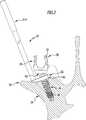
In
Selbstverständlich kann das Wirbelsäulenstabilisierungssystem
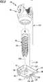
In
Bei den Knochenschrauben
Jedes der Pedikelschraubensysteme
An der Verbindungselementaufnahme
Zur Ausbildung eines Kugelgelenks
Am Schraubenkopf
Distalseitig schließt sich an den Gelenkkopf
Das Pedikelschraubensystem
Die Knochenausrichteinrichtung
Zum Koppeln des Schraubenschafts
Das erste Kopplungselement
Bei dem in den Figuren dargestellten Ausführungsbeispiel des Pedikelschraubensystems
Wie in den Figuren gut zu erkennen, ist der Kopplungsvorsprung
Die Kopplungsaufnahme
Die Knochenausrichteinrichtung
Ein Innendurchmesser
Bei dem in den Figuren dargestellten Ausführungsbeispiel definiert die Kopplungseinrichtung
Alternativ ist es auch denkbar, eine Längsachse der Kopplungseinrichtung
Ferner umfasst die Knochenausrichteinrichtung
Die Kupplungseinrichtung
Die Kupplungsausnehmung
Um eine einfache und sichere Verbindung zwischen dem Ausrichtinstrument
Die Funktionsweise des Wirbelsäulenstabilisierungssystems
Zum Einbringen der Pedikelschraube
Vor dem Einschrauben kann die Knochenausrichteinrichtung
Um eine sichere Orientierung und Befestigung der Pedikelschraube
Ist die Pedikelschraube
In der beschriebenen Weise kann jede der Pedikelschrauben
Dadurch, dass die Schraubenköpfe
Das vorgeschlagene Pedikelschraubensystem
BezugszeichenlisteLIST OF REFERENCE NUMBERS
- 1010
- Wirbelsäulenstabilisierungssystem Spine stabilization system
- 1212
- Knochenschraube bone screw
- 1414
- Verbindungselement connecting element
- 1616
- Wirbel whirl
- 1818
- Wirbelsäule spinal column
- 2020
- Pedikelschraubensystem pedicle screw system
- 2222
- Fixierschraube fixing screw
- 2424
- Pedikelschraube pedicle screw
- 2626
- Schraubenschaft screw shaft
- 2828
- Außengewinde external thread
- 3030
- Schraubenkopf screw head
- 3232
- Schenkel leg
- 3434
- Verbindungselementaufnahme Connecting element receptacle
- 3636
- Innengewinde inner thread
- 3838
- Außengewinde external thread
- 4040
- Kugelgelenk ball joint
- 4242
- Gelenkkopf joint head
- 4444
- Endfläche end face
- 4646
- Gelenkkopffläche Condyle surface
- 4848
- Werkzeugelementaufnahme Tool element receiver
- 5050
- Gelenkkopfaufnahme Joint head receptacle
- 5252
- Sitz Seat
- 5454
- Durchbrechung perforation
- 5656
- Ende The End
- 5858
- Schaftabschnitt shank portion
- 6060
- Ringflansch annular flange
- 6262
- Knochenausrichteinrichtung Knochenausrichteinrichtung
- 6464
- Kopplungseinrichtung coupling device
- 6666
- Knochenplatte bone plate
- 6868
- Oberseite top
- 7070
- Unterseite bottom
- 72 72
- Knochenverankerungselement Bone anchoring element
- 7474
- Knochenpin bone pin
- 7676
- erstes Kopplungselement first coupling element
- 7878
- zweites Kopplungselement second coupling element
- 8080
- Kopplungsvorsprung coupling projection
- 8282
- Kopplungsaufnahme female coupling
- 8484
- Außendurchmesser outer diameter
- 8686
- Außendurchmesser outer diameter
- 8888
- Ausnehmung recess
- 9090
- Schraubenschaftaufnahme Screw shaft receiver
- 9292
- Durchbrechung perforation
- 9494
- Innendurchmesser Inner diameter
- 9696
- Innendurchmesser Inner diameter
- 9898
- Ringfläche ring surface
- 100100
- Ringfläche ring surface
- 102102
- Längsachse longitudinal axis
- 104104
- Schraubenschaftlängsachse Screw shaft longitudinal axis
- 106106
- Längsachse longitudinal axis
- 108108
- Längsachse longitudinal axis
- 110110
- Neigungswinkel tilt angle
- 112112
- Kupplungseinrichtung coupling device
- 114114
- Ausrichtinstrument alignment instrument
- 116116
- Kupplungselement coupling member
- 118118
- Kupplungsausnehmung coupling recess
- 120120
- Durchbrechung perforation
- 122122
- Bohrung drilling
- 124124
- Ende The End
- 126126
- Außengewinde external thread
- 128128
- Kupplungsende coupling end
- 130130
- Gewinde thread
- 132132
- Innengewinde inner thread
- 134134
- Gewinde thread
- 136136
- Außengewinde external thread
- 138138
- Griffelement handle element
ZITATE ENTHALTEN IN DER BESCHREIBUNG QUOTES INCLUDE IN THE DESCRIPTION
Diese Liste der vom Anmelder aufgeführten Dokumente wurde automatisiert erzeugt und ist ausschließlich zur besseren Information des Lesers aufgenommen. Die Liste ist nicht Bestandteil der deutschen Patent- bzw. Gebrauchsmusteranmeldung. Das DPMA übernimmt keinerlei Haftung für etwaige Fehler oder Auslassungen.This list of the documents listed by the applicant has been generated automatically and is included solely for the better information of the reader. The list is not part of the German patent or utility model application. The DPMA assumes no liability for any errors or omissions.
Zitierte PatentliteraturCited patent literature
- DE 102013100574 A1[0003]DE 102013100574 A1[0003]
Claims (24)
Translated fromGermanPriority Applications (4)
| Application Number | Priority Date | Filing Date | Title |
|---|---|---|---|
| DE102014117175.6ADE102014117175A1 (en) | 2014-11-24 | 2014-11-24 | Pedicle screw system and spine stabilization system |
| US14/948,840US9848915B2 (en) | 2014-11-24 | 2015-11-23 | Pedicle screw system and spinal stabilization system |
| ES15195766TES2781855T3 (en) | 2014-11-24 | 2015-11-23 | Pedicle Screw System and Spinal Stabilization System |
| EP15195766.9AEP3023066B8 (en) | 2014-11-24 | 2015-11-23 | Pedicle screw system and spinal column-stabilizing system |
Applications Claiming Priority (1)
| Application Number | Priority Date | Filing Date | Title |
|---|---|---|---|
| DE102014117175.6ADE102014117175A1 (en) | 2014-11-24 | 2014-11-24 | Pedicle screw system and spine stabilization system |
Publications (1)
| Publication Number | Publication Date |
|---|---|
| DE102014117175A1true DE102014117175A1 (en) | 2016-05-25 |
Family
ID=54703813
Family Applications (1)
| Application Number | Title | Priority Date | Filing Date |
|---|---|---|---|
| DE102014117175.6AWithdrawnDE102014117175A1 (en) | 2014-11-24 | 2014-11-24 | Pedicle screw system and spine stabilization system |
Country Status (4)
| Country | Link |
|---|---|
| US (1) | US9848915B2 (en) |
| EP (1) | EP3023066B8 (en) |
| DE (1) | DE102014117175A1 (en) |
| ES (1) | ES2781855T3 (en) |
Families Citing this family (5)
| Publication number | Priority date | Publication date | Assignee | Title |
|---|---|---|---|---|
| US9585697B2 (en)* | 2011-04-01 | 2017-03-07 | Rebecca Elizabeth Stachniak | Posterior stabilization systems and methods |
| US9918763B2 (en)* | 2015-07-24 | 2018-03-20 | Warsaw Orthopedic, Inc. | Bone fixation element and methods of use |
| EP4278998B1 (en)* | 2016-07-29 | 2025-05-21 | Zimmer Biomet Spine, Inc. | Bone anchor housing limiter |
| US12082848B2 (en)* | 2019-02-27 | 2024-09-10 | Orthopediatrics Corp. | Bone anchors with cord retention features |
| US12082849B2 (en)* | 2019-04-12 | 2024-09-10 | Orthopediatrics Corp. | Dual tether support of vertebra |
Citations (4)
| Publication number | Priority date | Publication date | Assignee | Title |
|---|---|---|---|---|
| US20080086131A1 (en)* | 2006-10-06 | 2008-04-10 | Depuy Spine, Inc. | Bone screw fixation |
| US7615069B2 (en)* | 2004-04-08 | 2009-11-10 | Globus Medical, Inc. | Load distribution crown |
| DE102012219630A1 (en)* | 2012-10-26 | 2014-04-30 | Premiere Medical Gmbh | Bone screw, head housing for a bone screw and reduction instrument |
| DE102013100574A1 (en) | 2013-01-21 | 2014-07-24 | Aesculap Ag | Implant system and fastener for an implant system |
Family Cites Families (52)
| Publication number | Priority date | Publication date | Assignee | Title |
|---|---|---|---|---|
| GB1551705A (en)* | 1975-04-28 | 1979-08-30 | Downs Surgicial Ltd | Surgial implant |
| FR2651992B1 (en)* | 1989-09-18 | 1991-12-13 | Sofamor | IMPLANT FOR ANTERIOR DORSO-LUMBAR SPINE OSTEOSYNTHESIS FOR CORRECTION OF CYPHOSIS. |
| US5306275A (en)* | 1992-12-31 | 1994-04-26 | Bryan Donald W | Lumbar spine fixation apparatus and method |
| SE9402130D0 (en)* | 1994-06-17 | 1994-06-17 | Sven Olerud | Device and method for plate fixation of legs |
| US5620443A (en)* | 1995-01-25 | 1997-04-15 | Danek Medical, Inc. | Anterior screw-rod connector |
| US5843082A (en)* | 1996-05-31 | 1998-12-01 | Acromed Corporation | Cervical spine stabilization method and system |
| US5849004A (en)* | 1996-07-17 | 1998-12-15 | Bramlet; Dale G. | Surgical anchor |
| US6139550A (en)* | 1997-02-11 | 2000-10-31 | Michelson; Gary K. | Skeletal plating system |
| FR2761876B1 (en) | 1997-04-09 | 1999-08-06 | Materiel Orthopedique En Abreg | INSTRUMENTATION OF LUMBAR OSTEOSYNTHESIS FOR CORRECTION OF SPONDYLOLISTHESIS BY POSTERIOR PATHWAY |
| US6454769B2 (en)* | 1997-08-04 | 2002-09-24 | Spinal Concepts, Inc. | System and method for stabilizing the human spine with a bone plate |
| US5899904A (en)* | 1998-10-19 | 1999-05-04 | Third Milennium Engineering, Llc | Compression locking vertebral body screw, staple, and rod assembly |
| US5947969A (en)* | 1998-10-19 | 1999-09-07 | Third Millennium Engineering, Llc | Rotatable locking vertebral body screw, staple and rod assembly |
| DE19848715C1 (en) | 1998-10-22 | 2000-08-24 | Aesculap Ag & Co Kg | Osteo-synthetic holding system has locking units for the holding rods of different dimensions for the holding rods to allow adjustments to the setting of the bones or fragments before final clamping |
| FR2810532B1 (en)* | 2000-06-26 | 2003-05-30 | Stryker Spine Sa | BONE IMPLANT WITH ANNULAR LOCKING MEANS |
| US6533787B1 (en)* | 2000-07-31 | 2003-03-18 | Sdgi Holdings, Inc. | Contourable spinal staple with centralized and unilateral prongs |
| US7766947B2 (en)* | 2001-10-31 | 2010-08-03 | Ortho Development Corporation | Cervical plate for stabilizing the human spine |
| US20040019353A1 (en)* | 2002-02-01 | 2004-01-29 | Freid James M. | Spinal plate system for stabilizing a portion of a spine |
| US7175623B2 (en)* | 2002-06-24 | 2007-02-13 | Lanx, Llc | Cervical plate with backout protection |
| CA2504215A1 (en)* | 2002-10-28 | 2004-05-13 | Blackstone Medical, Inc. | Bone plate assembly provided with screw locking mechanisms |
| AU2003287273C1 (en)* | 2002-10-30 | 2010-01-07 | Zimmer Spine, Inc. | Spinal stabilization system insertion and methods |
| US7524325B2 (en)* | 2002-11-04 | 2009-04-28 | Farid Bruce Khalili | Fastener retention system |
| FR2848413B1 (en)* | 2002-12-11 | 2005-07-29 | Fixano | OSTEOSYNTHESIS PLATE FOR OSTEOSYNTHESIS OF SMALL BONE NEIGHBORS OF OTHERS |
| FR2848408B1 (en)* | 2002-12-17 | 2005-08-19 | Vitatech | DEVICE WITH ANTERIOR PLATE FOR MAINTAINING THE RACHIS |
| US20040181227A1 (en)* | 2003-03-11 | 2004-09-16 | Farid Khalili | System and method for attaching a bone plate to bone |
| US7473267B2 (en)* | 2003-04-25 | 2009-01-06 | Warsaw Orthopedic, Inc. | System and method for minimally invasive posterior fixation |
| US6945975B2 (en)* | 2003-07-07 | 2005-09-20 | Aesculap, Inc. | Bone fixation assembly and method of securement |
| US7857839B2 (en)* | 2003-09-03 | 2010-12-28 | Synthes Usa, Llc | Bone plate with captive clips |
| US7909860B2 (en)* | 2003-09-03 | 2011-03-22 | Synthes Usa, Llc | Bone plate with captive clips |
| US7588588B2 (en)* | 2003-10-21 | 2009-09-15 | Innovative Spinal Technologies | System and method for stabilizing of internal structures |
| CA2449883A1 (en)* | 2003-11-18 | 2005-05-18 | Terray Corporation | Taper-lock bone screw fixation system |
| US7195633B2 (en)* | 2004-01-08 | 2007-03-27 | Robert J. Medoff | Fracture fixation system |
| US7740649B2 (en)* | 2004-02-26 | 2010-06-22 | Pioneer Surgical Technology, Inc. | Bone plate system and methods |
| US20050277937A1 (en)* | 2004-06-10 | 2005-12-15 | Leung Takkwong R | Bone plating system |
| US7883510B2 (en)* | 2004-08-27 | 2011-02-08 | Depuy Spine, Inc. | Vertebral staples and insertion tools |
| US7935137B2 (en)* | 2004-12-08 | 2011-05-03 | Depuy Spine, Inc. | Locking bone screw and spinal plate system |
| US7931678B2 (en)* | 2004-12-08 | 2011-04-26 | Depuy Spine, Inc. | Hybrid spinal plates |
| US7951172B2 (en)* | 2005-03-04 | 2011-05-31 | Depuy Spine Sarl | Constrained motion bone screw assembly |
| US8414616B2 (en)* | 2006-09-12 | 2013-04-09 | Pioneer Surgical Technology, Inc. | Mounting devices for fixation devices and insertion instruments used therewith |
| DE102006055599B4 (en) | 2006-11-24 | 2016-01-07 | Peter Brehm | Orthopedic fastening device and device for correcting spinal deformity |
| US20090062914A1 (en)* | 2007-08-29 | 2009-03-05 | Marino James F | Devices and methods for intervertebral therapy |
| EP2249717B1 (en) | 2008-01-14 | 2015-02-25 | K2M, Inc. | Spinal fixation device |
| US8282675B2 (en)* | 2008-01-25 | 2012-10-09 | Depuy Spine, Inc. | Anti-backout mechanism |
| US9504494B2 (en)* | 2008-04-28 | 2016-11-29 | DePuy Synthes Products, Inc. | Implants for securing spinal fixation elements |
| EP2135562B1 (en)* | 2008-06-20 | 2015-09-09 | Arthrex, Inc. | Wedged profile plate |
| US8419778B2 (en) | 2010-01-15 | 2013-04-16 | Ebi, Llc | Uniplanar bone anchor system |
| AU2011299558A1 (en)* | 2010-09-08 | 2013-05-02 | Roger P. Jackson | Dynamic stabilization members with elastic and inelastic sections |
| US10022171B2 (en) | 2011-07-26 | 2018-07-17 | Scott & White Healthcare | Bone screws and bone screw systems |
| US8740950B2 (en)* | 2011-12-08 | 2014-06-03 | Spine Wave, Inc. | Methods for percutaneously attaching a cross connector to contralateral spinal constructs |
| EP2604204B1 (en) | 2011-12-13 | 2014-10-01 | Biedermann Technologies GmbH & Co. KG | Monoplanar bone anchoring device with selectable pivot plane |
| US8470009B1 (en) | 2012-03-08 | 2013-06-25 | Warsaw Orthopedic, Inc. | Bone fastener and method of use |
| US9060815B1 (en)* | 2012-03-08 | 2015-06-23 | Nuvasive, Inc. | Systems and methods for performing spine surgery |
| US9517089B1 (en)* | 2013-10-08 | 2016-12-13 | Nuvasive, Inc. | Bone anchor with offset rod connector |
- 2014
- 2014-11-24DEDE102014117175.6Apatent/DE102014117175A1/ennot_activeWithdrawn
- 2015
- 2015-11-23ESES15195766Tpatent/ES2781855T3/enactiveActive
- 2015-11-23EPEP15195766.9Apatent/EP3023066B8/enactiveActive
- 2015-11-23USUS14/948,840patent/US9848915B2/enactiveActive
Patent Citations (4)
| Publication number | Priority date | Publication date | Assignee | Title |
|---|---|---|---|---|
| US7615069B2 (en)* | 2004-04-08 | 2009-11-10 | Globus Medical, Inc. | Load distribution crown |
| US20080086131A1 (en)* | 2006-10-06 | 2008-04-10 | Depuy Spine, Inc. | Bone screw fixation |
| DE102012219630A1 (en)* | 2012-10-26 | 2014-04-30 | Premiere Medical Gmbh | Bone screw, head housing for a bone screw and reduction instrument |
| DE102013100574A1 (en) | 2013-01-21 | 2014-07-24 | Aesculap Ag | Implant system and fastener for an implant system |
Also Published As
| Publication number | Publication date |
|---|---|
| EP3023066A1 (en) | 2016-05-25 |
| EP3023066B1 (en) | 2020-02-26 |
| ES2781855T3 (en) | 2020-09-08 |
| US20160143667A1 (en) | 2016-05-26 |
| US9848915B2 (en) | 2017-12-26 |
| EP3023066B8 (en) | 2020-04-08 |
Similar Documents
| Publication | Publication Date | Title |
|---|---|---|
| EP2692304B1 (en) | Set of surgical instruments | |
| EP3454767B1 (en) | Medical instrument for provisionally fastening a polyaxial pedicle screw | |
| DE69723108T2 (en) | ADJUSTABLE OSTEOSYNTHESIS DEVICE FOR THE SPINE AND POSITIONING TOOL | |
| DE102004027881B4 (en) | Bone screw and osteosynthesis device | |
| EP3023065B1 (en) | Pedicle screw system and spinal column-stabilizing system | |
| DE69726746T2 (en) | MULTI-AXIS BONE SCREW ARRANGEMENT | |
| DE60023323T2 (en) | Multi-axis bone screw arrangement | |
| DE69428780T2 (en) | PLATE PART FOR THE FRONT SIDE OF THE Cervical Spine | |
| EP2266483B1 (en) | Surgical bone anchoring device and spinal column fixation system | |
| EP2962651B1 (en) | Medical screwdriver and shaft for the medical screwdriver | |
| EP1392190B1 (en) | Manipulator for handling a pedicule screw | |
| DE102005009282A1 (en) | Fixing element for a bone implant system comprises a fixing part with a fixing section on the distal side and a receiving part connected to the fixing part | |
| DE102015008036A1 (en) | Pedicle screw with tulip | |
| EP3383291B1 (en) | Medical instrument and medical equipment | |
| DE202009018581U1 (en) | Adjustable bar arrangement | |
| DE102013107498A1 (en) | Spine stabilization system and surgical fastener for a spine stabilization system | |
| EP3954312A1 (en) | Surgical instrument | |
| EP1261288A1 (en) | Connector element for bone rods or spinal rods | |
| EP3023066B1 (en) | Pedicle screw system and spinal column-stabilizing system | |
| DE102014109935B4 (en) | Positioning device for fixing an intramedullary nail in a long bone | |
| WO2003011156A1 (en) | Connecting element | |
| EP3031416A1 (en) | Osteosynthesis device | |
| EP1269929A1 (en) | Connection system for the spinal fusion of the lumbar column | |
| DE10005134B4 (en) | Grafting system for spinal fusion of the lumbar spine and pedicle screw and anvil for use in such | |
| EP2768401B1 (en) | Mtv implantation set |
Legal Events
| Date | Code | Title | Description |
|---|---|---|---|
| R163 | Identified publications notified | ||
| R082 | Change of representative | Representative=s name:HOEGER, STELLRECHT & PARTNER PATENTANWAELTE MB, DE | |
| R082 | Change of representative | Representative=s name:HOEGER, STELLRECHT & PARTNER PATENTANWAELTE MB, DE | |
| R005 | Application deemed withdrawn due to failure to request examination |