DE102014115600A1 - Surgical instrument with a manual control device - Google Patents
Surgical instrument with a manual control deviceDownload PDFInfo
- Publication number
- DE102014115600A1 DE102014115600A1DE102014115600.5ADE102014115600ADE102014115600A1DE 102014115600 A1DE102014115600 A1DE 102014115600A1DE 102014115600 ADE102014115600 ADE 102014115600ADE 102014115600 A1DE102014115600 A1DE 102014115600A1
- Authority
- DE
- Germany
- Prior art keywords
- point
- articulation
- control device
- lever
- surgical instrument
- Prior art date
- Legal status (The legal status is an assumption and is not a legal conclusion. Google has not performed a legal analysis and makes no representation as to the accuracy of the status listed.)
- Withdrawn
Links
Images


Classifications
- A—HUMAN NECESSITIES
- A61—MEDICAL OR VETERINARY SCIENCE; HYGIENE
- A61B—DIAGNOSIS; SURGERY; IDENTIFICATION
- A61B17/00—Surgical instruments, devices or methods
- A61B17/00234—Surgical instruments, devices or methods for minimally invasive surgery
- A—HUMAN NECESSITIES
- A61—MEDICAL OR VETERINARY SCIENCE; HYGIENE
- A61B—DIAGNOSIS; SURGERY; IDENTIFICATION
- A61B17/00—Surgical instruments, devices or methods
- A61B17/28—Surgical forceps
- A61B17/29—Forceps for use in minimally invasive surgery
- A61B17/2909—Handles
- A—HUMAN NECESSITIES
- A61—MEDICAL OR VETERINARY SCIENCE; HYGIENE
- A61B—DIAGNOSIS; SURGERY; IDENTIFICATION
- A61B34/00—Computer-aided surgery; Manipulators or robots specially adapted for use in surgery
- A61B34/70—Manipulators specially adapted for use in surgery
- A—HUMAN NECESSITIES
- A61—MEDICAL OR VETERINARY SCIENCE; HYGIENE
- A61B—DIAGNOSIS; SURGERY; IDENTIFICATION
- A61B34/00—Computer-aided surgery; Manipulators or robots specially adapted for use in surgery
- A61B34/70—Manipulators specially adapted for use in surgery
- A61B34/74—Manipulators with manual electric input means
- A—HUMAN NECESSITIES
- A61—MEDICAL OR VETERINARY SCIENCE; HYGIENE
- A61B—DIAGNOSIS; SURGERY; IDENTIFICATION
- A61B34/00—Computer-aided surgery; Manipulators or robots specially adapted for use in surgery
- A61B34/70—Manipulators specially adapted for use in surgery
- A61B34/76—Manipulators having means for providing feel, e.g. force or tactile feedback
- A—HUMAN NECESSITIES
- A61—MEDICAL OR VETERINARY SCIENCE; HYGIENE
- A61B—DIAGNOSIS; SURGERY; IDENTIFICATION
- A61B17/00—Surgical instruments, devices or methods
- A61B2017/00367—Details of actuation of instruments, e.g. relations between pushing buttons, or the like, and activation of the tool, working tip, or the like
- A61B2017/00398—Details of actuation of instruments, e.g. relations between pushing buttons, or the like, and activation of the tool, working tip, or the like using powered actuators, e.g. stepper motors, solenoids
- A—HUMAN NECESSITIES
- A61—MEDICAL OR VETERINARY SCIENCE; HYGIENE
- A61B—DIAGNOSIS; SURGERY; IDENTIFICATION
- A61B17/00—Surgical instruments, devices or methods
- A61B2017/0042—Surgical instruments, devices or methods with special provisions for gripping
- A61B2017/00424—Surgical instruments, devices or methods with special provisions for gripping ergonomic, e.g. fitting in fist
- A—HUMAN NECESSITIES
- A61—MEDICAL OR VETERINARY SCIENCE; HYGIENE
- A61B—DIAGNOSIS; SURGERY; IDENTIFICATION
- A61B17/00—Surgical instruments, devices or methods
- A61B2017/0046—Surgical instruments, devices or methods with a releasable handle; with handle and operating part separable
- A—HUMAN NECESSITIES
- A61—MEDICAL OR VETERINARY SCIENCE; HYGIENE
- A61B—DIAGNOSIS; SURGERY; IDENTIFICATION
- A61B17/00—Surgical instruments, devices or methods
- A61B2017/00477—Coupling
- A—HUMAN NECESSITIES
- A61—MEDICAL OR VETERINARY SCIENCE; HYGIENE
- A61B—DIAGNOSIS; SURGERY; IDENTIFICATION
- A61B17/00—Surgical instruments, devices or methods
- A61B17/28—Surgical forceps
- A61B17/29—Forceps for use in minimally invasive surgery
- A61B17/2909—Handles
- A61B2017/2912—Handles transmission of forces to actuating rod or piston
- A61B2017/2919—Handles transmission of forces to actuating rod or piston details of linkages or pivot points
Landscapes
- Health & Medical Sciences (AREA)
- Surgery (AREA)
- Life Sciences & Earth Sciences (AREA)
- Engineering & Computer Science (AREA)
- Medical Informatics (AREA)
- Biomedical Technology (AREA)
- Heart & Thoracic Surgery (AREA)
- Nuclear Medicine, Radiotherapy & Molecular Imaging (AREA)
- Molecular Biology (AREA)
- Animal Behavior & Ethology (AREA)
- General Health & Medical Sciences (AREA)
- Public Health (AREA)
- Veterinary Medicine (AREA)
- Robotics (AREA)
- Ophthalmology & Optometry (AREA)
- Surgical Instruments (AREA)
Abstract
Translated fromGermanDescription
Translated fromGermanDie vorliegende Erfindung betrifft ein chirurgisches Instrument mit einer manuellen Steuervorrichtung für eine Betätigung mit der Hand, wobei die Steuervorrichtung zwischen einer geschlossenen Position und einer geöffneten Position verlagert werden kann. Die Verlagerung erfolgt mittels manueller Einwirkung auf die Steuervorrichtung durch die Hand eines Benutzers, indem dieser die Hand öffnet und schließt.The present invention relates to a surgical instrument having a manual control device for manual operation, wherein the control device can be displaced between a closed position and an open position. The displacement takes place by means of manual action on the control device by the hand of a user, who opens and closes his hand.
Es gibt eine Vielzahl von Werkzeugen und Instrumenten, die ein Benutzer manuell mit seiner Hand betätigt. Einige dieser Instrumente erfordern bei der Betätigung eine besondere Ergonomie, z.B. weil die Betätigung des Instruments besonders feinfühlig möglich sein muss, eine häufige wiederholte Betätigung des Instruments erforderlich ist oder bestimmte Betätigungspositionen des Instruments über längere Zeit konstant gehalten werden müssen.There are a variety of tools and instruments that a user manually operates with his hand. Some of these instruments require special ergonomics when operated, e.g. because the operation of the instrument must be particularly sensitive possible, frequent repeated operation of the instrument is required or certain operating positions of the instrument must be kept constant for a long time.
Zu diesen Instrumenten zählen auch chirurgische Instrumente, insbesondere minimalinvasive chirurgische Instrumente. Diese haben am proximalen Ende mindestens einen Griff, der es einem Benutzer, insbesondere einem Chirurgen oder einem Assistenten, erlaubt, das Instrument zu halten und zu betätigen. Solche Instrumente müssen ergonomisch greifbar und ergonomisch betätigbar sein, dies auch für beliebige Handgrößen. Schließlich muss es dem Benutzer auch möglich sein, wiederholt auf bequeme Weise und in verschiedenen Lagen der Steuervorrichtung eine ausreichende Kraft auf die Steuervorrichtung ausüben zu können.These instruments also include surgical instruments, especially minimally invasive surgical instruments. These have at least one handle at the proximal end, which allows a user, in particular a surgeon or an assistant, to hold and manipulate the instrument. Such instruments must be ergonomically available and ergonomically operable, this also for any hand sizes. Finally, the user must also be able to repeatedly exert a sufficient force on the control device in a comfortable manner and in different positions of the control device.
Eine Vielzahl der Griffe für solche Instrumente sind im Wesentlichen pistolenförmig. Diese Griffform kann in einem breiten Winkelbereich gut gegriffen werden, wobei auch in unterschiedlichen Lagen und bei ungünstigen Haltewinkeln gut gearbeitet werden kann. Oft verfügen diese Griffe über Fingerschlaufen, mit denen ausreichend feinfühlig gearbeitet werden kann.A variety of handles for such instruments are essentially pistol-shaped. This handle shape can be easily gripped in a wide angle range, which also works well in different positions and unfavorable brackets. Often these handles have finger loops that can be used with sufficient sensitivity.
In diesem Zusammenhang sei lediglich beispielhaft auf die Steuervorrichtungen hingewiesen, die in
Trotz der großen Anzahl an manuellen Steuervorrichtungen besteht auch weiterhin ein Bedarf an Steuervorrichtungen, die dem Benutzer eine bequeme und intuitive Bedienung auch über einen längeren Zeitraum ermöglichen.Despite the large number of manual control devices, there is still a need for control devices that allow the user to operate conveniently and intuitively, even over an extended period of time.
Es ist eine Aufgabe der vorliegenden Erfindung, ein verbessertes chirurgisches Instrument mit einer manuellen Steuervorrichtung für eine Betätigung mit der Hand aufzuzeigen, die eine bequeme und ergonomische Betätigung, insbesondere durch ein Öffnen und Schließen der Hand, ermöglicht.It is an object of the present invention to provide an improved surgical instrument having a manual control device for manual operation, which enables comfortable and ergonomic operation, in particular by opening and closing the hand.
Bei einem ersten Aspekt wird die Aufgabe gelöst durch ein chirurgisches Instrument mit einer manuellen Steuervorrichtung für eine Betätigung mit einer Hand, wobei die Steuervorrichtung zwischen einer geschlossenen Position und einer geöffneten Position verlagert werden kann und die Steuervorrichtung aufweist:
- – einen Fingerhebel mit einem ersten Anlenkpunkt und einem zweiten Anlenkpunkt, wobei der Fingerhebel einen Fingerauflageabschnitt aufweist, der ausgehend vom ersten Anlenkpunkt als Fortsatz einer ersten Erstreckung des Fingerhebels zwischen dem zweiten Anlenkpunkt und dem ersten Anlenkpunkt ausgebildet ist,
- – ein Zentralelement mit einem dritten Anlenkpunkt und einem vierten Anlenkpunkt,
- – einen Verbindungshebel, der am ersten Anlenkpunkt und am dritten Anlenkpunkt verschwenkbar angeordnet ist, so dass der Verbindungshebel relativ zum Zentralelement und relativ zum Fingerhebel verschwenkbar ist und dass der erste Anlenkpunkt entlang einer ersten gekrümmten Bahn um den dritten Anlenkpunkt herum geführt verlagerbar ist,
- – einen Daumenhebel, der am zweiten Anlenkpunkt und am vierten Anlenkpunkt verschwenkbar angeordnet ist, so dass der Daumenhebel relativ zum Zentralelement und relativ zum Fingerhebel verschwenkbar ist und dass der zweite Anlenkpunkt entlang einer zweiten gekrümmten Bahn um den vierten Anlenkpunkt herum geführt verlagerbar ist.
- A finger lever having a first articulation point and a second articulation point, the finger lever having a finger rest section which, starting from the first articulation point, is formed as an extension of a first extension of the finger lever between the second articulation point and the first articulation point,
- A central element with a third articulation point and a fourth articulation point,
- A connecting lever, which is arranged pivotably at the first articulation point and at the third articulation point, so that the connecting lever can be pivoted relative to the central element and relative to the finger lever and that the first articulation point can be displaced along a first curved path around the third articulation point,
- - A thumb lever which is pivotally mounted at the second pivot point and at the fourth pivot point, so that the thumb lever is pivotable relative to the central element and relative to the finger lever and that the second pivot point is guided along a second curved path around the fourth pivot point around displaced.
Im Rahmen der zu erzielenden Verbesserung wurde erkannt, dass es ein Problem bei bekannten manuellen Steuervorrichtungen ist, dass diese die tatsächliche Bewegung der Hand eines Benutzers beim Öffnen und Schließen der Hand nicht ausreichend berücksichtigen. Dies führt dazu, dass bekannte manuelle Steuervorrichtungen zwar bei Betrachtung der vorgeschlagenen Technik als ergonomisch und bequem bedienbar erscheinen, dies in der Praxis, gerade bei länger andauernden Prozeduren, vom Benutzer nicht so empfunden wird.Within the scope of the improvement to be achieved, it has been recognized that a problem with known manual control devices is that they do not sufficiently take into account the actual movement of a user's hand when opening and closing the hand. As a result, although known manual control devices appear to be ergonomically and comfortably operable upon consideration of the proposed technique, this is not perceived by the user in practice, especially with prolonged procedures.
In diesem Zusammenhang wurde ferner erkannt, dass zumindest ein Teil der Problematik darin zu liegen scheint, dass sich Daumen und Finger einer Hand beim Öffnen nicht wie bei einem Scharnier genau auf einer Kreisbahn bewegen. Vielmehr wurde erkannt, dass sich Daumen und Finger beim Öffnen der Hand zunächst fast geradlinig voneinander entfernen. Der Daumen schwenkt dann recht schnell auf eine gekrümmte Bahn ein, insbesondere eine Kreisbahn, während die Finger sich weiterhin auf einer zumindest in etwa geradlinigen Bahn fortbewegen. Erst nachdem der Öffnungsprozess der Hand schon deutlich fortgeschritten ist, schwenken auch die Finger auf eine gekrümmte Bahn ein, insbesondere auf eine Kreisbahn.In this context, it was further recognized that at least part of the problem seems to lie in the fact that thumb and fingers of a hand when opening do not move exactly like a hinge on a circular path. Rather, it was recognized that the thumb and fingers when opening the hand first almost straight away from each other. The thumb then pivots quite quickly on a curved path, in particular a circular path, while the fingers continue on one at least move in a roughly rectilinear path. Only after the opening process of the hand is already clearly advanced, the fingers also pivot on a curved path, in particular on a circular path.
Bei der hier offenbarten manuellen Steuervorrichtung wurde zudem berücksichtigt, dass eine solche Steuervorrichtung auch kostengünstig zu realisieren sein soll. Daher wurde gezielt nach einer Lösung gesucht, die die natürliche Öffnungsbewegung der Hand besser nachempfindet und dennoch einen möglichst einfachen mechanischen Aufbau hat. Ein mechanisch einfacher Aufbau bietet dabei sowohl Vorteile im Hinblick auf die Zuverlässigkeit der Steuervorrichtung als auch im Hinblick auf eine kostengünstige Fertigung der Steuervorrichtung.In the case of the manual control device disclosed here, it has also been taken into consideration that such a control device should also be cost-effective to implement. Therefore, a solution was sought which better simulates the natural opening movement of the hand and still has the simplest possible mechanical structure. A mechanically simple construction offers both advantages with regard to the reliability of the control device and with regard to cost-effective production of the control device.
Eine Besonderheit der offenbarten manuellen Steuervorrichtung ist, dass sich die verschiedenen Hebel, also Fingerhebel, Verbindungshebel und Daumenhebel, zwar um Anlenkpunkte verschwenken, sich also eigentlich auf einer kreisförmigen Bahn bewegen, sich aber gleichzeitig zumindest einer der Anlenkpunkte, insbesondere genau zwei oder mindestens zwei der Anlenkpunkte, verlagert, so dass das distale Ende des Fingerhebels zumindest während eines Abschnitts des Öffnungsvorgangs sich entlang eines zumindest ungefähr linearen Wegs verlagert.A special feature of the disclosed manual control device is that the various levers, ie finger lever, connecting lever and thumb lever, although pivot about articulation points, so actually move on a circular path, but at the same time at least one of the articulation points, in particular exactly two or at least two of Anchored points, so that the distal end of the finger lever, at least during a portion of the opening process, moves along an at least approximately linear path.
Bei einigen bevorzugten Ausgestaltungen wird die Bewegung mindestens eines der genannten Hebel mechanisch oder elektrisch erfasst und zum Betätigen, insbesondere für ein Öffnen und Schließen, des chirurgischen Instruments verwendet. Bei einigen bevorzugten Ausgestaltungen bewegen sich bei einer Betrachtung entlang der Längsrichtung der erste Anlenkpunkt und der zweite Anlenkpunkt beim Öffnen der Steuervorrichtung in Richtung der distalen Seite und beim Schließen in Richtung der proximalen Seite. Bei einigen bevorzugten Ausgestaltungen hat der Fingerauflageabschnitt eine Breite senkrecht zur Längsrichtung und, insbesondere, auch senkrecht zur Höhenrichtung von mindestens 5 mm, bevorzugt mindestens 10 mm, besonders bevorzugt von mindestens 20 mm und insbesondere von mindestens 30 mm.In some preferred embodiments, the movement of at least one of said levers is mechanically or electrically detected and used to actuate, in particular for opening and closing, the surgical instrument. In some preferred embodiments, when viewed along the longitudinal direction, the first hinge point and the second hinge point move toward the distal side upon opening of the control device and toward the proximal side when closing. In some preferred embodiments, the finger rest portion has a width perpendicular to the longitudinal direction and, in particular, also perpendicular to the height direction of at least 5 mm, preferably at least 10 mm, more preferably at least 20 mm and in particular at least 30 mm.
Für eine vereinfachte Orientierung sollen hier und im Folgenden die Begriffe distal und proximal wie folgt verwendet werden. Als proximal soll der Teil der Steuervorrichtung verstanden werden, der dem Mittelpunkt einer Hand des Benutzers am nächsten ist, wenn dieser seine Hand auf oder in die Steuervorrichtung gelegt hat. Die distale Seite der Steuervorrichtung liegt in Längserstreckung der Steuervorrichtung der proximalen Seite gegenüber. Hier befinden sich die Fingerspitzen des Benutzers, wenn er seine Hand auf oder in die Steuervorrichtung gelegt hat. Die Längsrichtung von proximal nach distal kann dabei insbesondere als eine Gerade verstanden werden, die bei geschlossener Steuervorrichtung durch den zweiten und den dritten Anlenkpunkt führt. Diese Orientierungshilfen dienen lediglich einem besseren Verständnis der Erfindung.For a simplified orientation, the terms distal and proximal are to be used here and below as follows. The term "proximal" is understood to mean that part of the control device which is closest to the center of a user's hand when it has laid its hand on or in the control device. The distal side of the control device is located in the longitudinal extension of the control device of the proximal side. Here are the user's fingertips when he puts his hand on or in the control device. The longitudinal direction from proximal to distal can be understood in particular as a straight line that leads through the second and the third point of articulation when the control device is closed. These guidelines are only for a better understanding of the invention.
Wie anhand von Ausführungsbeispielen später noch verdeutlicht wird, verlagert sich ein erstes distales Ende des Fingerhebels während eines Abschnitts des Öffnungsvorgangs, insbesondere zu Beginn des Öffnungsvorgangs, derart, dass die Position des ersten distalen Endes bezogen auf die Längsrichtung zumindest im Wesentlichen unverändert bleibt. Dies wird u.a. dadurch erreicht, dass während sich der Fingerhebel um den ersten Anlenkpunkt verschwenkt, der erste Anlenkpunkt gleichzeitig in Richtung der distalen Seite verlagert wird. So wird die Drehbewegung des Fingerhebels um den ersten Anlenkpunkt, die eigentlich eine Verlagerung des ersten distalen Endes in Richtung der proximalen Seite bewirken würde, durch die Verlagerung des ersten Anlenkpunkts in Richtung der distalen Seite zumindest teilweise kompensiert oder überkompensiert.As will be clarified by means of embodiments, a first distal end of the finger lever during a portion of the opening process, in particular at the beginning of the opening process, displaced such that the position of the first distal end with respect to the longitudinal direction remains at least substantially unchanged. This is u.a. achieved in that while the finger lever pivots about the first pivot point, the first pivot point is displaced simultaneously in the direction of the distal side. Thus, the rotational movement of the finger lever about the first articulation point, which would actually cause a displacement of the first distal end in the direction of the proximal side, is at least partially compensated or overcompensated by the displacement of the first articulation point in the direction of the distal side.
Um die Kompensation bzw. Überkompensation besser zu verstehen, sei nachfolgend angenommen, dass sich das erste distale Ende des Fingerhebels beim Öffnen um eine Strecke x entlang der Längsrichtung verlagert und entlang einer Strecke y entlang einer Höhenrichtung verlagert, die senkrecht zur Längsrichtung steht. Bei einigen bevorzugten Ausgestaltungen ist die Kompensation bzw. Überkompensation derart gewählt, dass die Strecke x, entweder in Richtung der distalen Seite oder in Richtung der proximalen Seite bei einem Öffnen der Steuervorrichtung um 45° ausgehend von der geschlossenen Position höchstens 0,25y, bevorzugt 0,2y, besonders bevorzugt 0,15y und insbesondere 0,1y beträgt. Zusätzlich oder alternativ ist die Kompensation bzw. Überkompensation derart gewählt, dass die Strecke x, entweder in Richtung der distalen Seite oder in Richtung der proximalen Seite bei einem Öffnen der Steuervorrichtung um 30° ausgehend von der geschlossenen Position höchstens 0,2y, bevorzugt 0,15y, besonders bevorzugt 0,1y und insbesondere 0,05y beträgt.In order to better understand the compensation or overcompensation, it is assumed below that the first distal end of the finger lever is displaced by a distance x along the longitudinal direction during opening and displaced along a distance y along a vertical direction which is perpendicular to the longitudinal direction. In some preferred embodiments, the compensation or overcompensation is chosen such that the distance x, either in the direction of the distal side or in the direction of the proximal side at an opening of the control device by 45 ° from the closed position at most 0.25y, preferably 0 , 2y, more preferably 0.15y and especially 0.1y. Additionally or alternatively, the compensation or overcompensation is selected such that the distance x, either in the direction of the distal side or in the direction of the proximal side at an opening of the control device by 30 ° from the closed position at most 0,2y, preferably 0, 15y, more preferably 0.1y and especially 0.05y.
Bei einigen bevorzugten Ausgestaltungen ist die Steuervorrichtung derart ausgebildet, dass das Zentralelement bei einem Öffnen und Schließen der Steuervorrichtung relativ zu einem Handmittelpunkt ruht. Dies bedeutet, dass sich zwar die genannten Hebel verlagern, die Steuervorrichtung insgesamt aber bezogen auf den Handmittelpunkt ruht. Insbesondere wenn das Zentralelement mit einem chirurgischen Instrument gekoppelt ist, kann auf diese Weise erreicht werden, dass auch bei einem Öffnen und Schließen der Steuervorrichtung der Handmittelpunkt relativ zu dem chirurgischen Instrument ruht. Mit anderen Worten, ein Öffnen und Schließen der Steuervorrichtung bewirkt keine Verlagerung des Zentralelements oder des chirurgischen Instruments in Längsrichtung.In some preferred embodiments, the control device is configured such that the central element rests relative to a hand center point upon opening and closing of the control device. This means that, although the said levers shift, the control device as a whole rests relative to the center of the hand. In particular, when the central element is coupled to a surgical instrument, it can be achieved in this way that, even when the control device is opened and closed, the midpoint of the hand is relative to the surgical instrument rests. In other words, opening and closing the control device does not cause longitudinal displacement of the central element or the surgical instrument.
Bei einigen bevorzugten Ausgestaltungen beträgt eine Länge des Fingerauflageabschnitts zwischen 35% und 95% der Länge des Fingerhebels, bevorzugt zwischen 45% und 90%, besonders bevorzugt zwischen 55% und 85% und insbesondere zwischen 65% und 80%. Unter der Länge des Fingerauflageabschnitts soll dabei die Strecke vom ersten Anlenkpunkt zum distalen Ende des Fingerhebels verstanden werden. Unter der Länge des Fingerhebels soll die Strecke vom zweiten Anlenkpunkt über den ersten Anlenkpunkt bis zum distalen Ende des Fingerhebels verstanden werden.In some preferred embodiments, a length of the finger rest portion is between 35% and 95% of the length of the finger lever, preferably between 45% and 90%, more preferably between 55% and 85%, and most preferably between 65% and 80%. The length of the finger rest section should be understood to mean the distance from the first articulation point to the distal end of the finger lever. The length of the finger lever should be understood as the distance from the second point of articulation via the first point of articulation to the distal end of the finger lever.
Bei einigen bevorzugten Ausgestaltungen verlaufen die Schwenkachsen, also die Achsen, um die sich die Hebel an den Anlenkpunkten relativ zueinander oder relativ zum Zentralelement verschwenken, im Wesentlichen parallel zueinander. Zusätzlich oder alternativ verlaufen die Schwenkachsen quer zu einer auf die Steuervorrichtung aufliegenden Hand. Die Schwenkachsen können auch als parallel zu einer Breitenrichtung verstanden werden, die sowohl zur Längsrichtung als auch zur Höhenrichtung senkrecht steht.In some preferred embodiments, the pivot axes, ie the axes about which the levers pivot at the articulation points relative to one another or relative to the central element, run essentially parallel to one another. Additionally or alternatively, the pivot axes extend transversely to a hand resting on the control device. The pivot axes can also be understood as parallel to a width direction that is perpendicular to both the longitudinal direction and the height direction.
Bei der ersten gekrümmten Bahn und/oder der zweiten gekrümmten Bahn handelt es sich insbesondere um eine Kreisbahn.The first curved path and / or the second curved path is in particular a circular path.
Damit ist die Aufgabe vollständig gelöst. Bei einer bevorzugten Weiterbildung weist der Daumenhebel einen Daumenauflageabschnitt auf, der ausgehend vom vierten Anlenkpunkt als Fortsatz einer zweiten Erstreckung des Daumenhebels zwischen dem zweiten Anlenkpunkt und dem vierten Anlenkpunkt ausgebildet ist.This completes the task. In a preferred development, the thumb lever has a thumb rest section which, starting from the fourth articulation point, is designed as an extension of a second extension of the thumb lever between the second articulation point and the fourth articulation point.
Bei dieser Weiterbildung wird auch der Daumen der Hand in die Bewegung beim Öffnen und Schließen der Steuervorrichtung einbezogen. Dies erlaubt eine besonders natürliche Betätigung mit der Hand. Bei einigen bevorzugten Ausgestaltungen beträgt eine Länge des Daumenauflageabschnitts zwischen 35% und 95% der Länge des Daumenhebels, bevorzugt zwischen 45% und 85%, besonders bevorzugt zwischen 55% und 75% und insbesondere zwischen 60% und 70%. Unter der Länge des Daumenauflageabschnitts soll dabei die Strecke vom vierten Anlenkpunkt zum distalen Ende des Daumenhebels verstanden werden. Unter der Länge des Daumenhebels soll die Strecke vom zweiten Anlenkpunkt über den vierten Anlenkpunkt bis zum distalen Ende des Daumenhebels verstanden werden.In this development, the thumb of the hand is included in the movement when opening and closing the control device. This allows a particularly natural operation by hand. In some preferred embodiments, a length of the thumb rest portion is between 35% and 95% of the length of the thumb lever, preferably between 45% and 85%, more preferably between 55% and 75%, and most preferably between 60% and 70%. The length of the thumb rest section should be understood to mean the distance from the fourth articulation point to the distal end of the thumb lever. The length of the thumb lever should be understood as the distance from the second articulation point via the fourth articulation point to the distal end of the thumb lever.
Bei einer vorteilhaften Weiterbildung weist der Verbindungshebel einen Betätigungsabschnitt auf, der ausgehend vom dritten Anlenkpunkt als Fortsatz einer dritten Erstreckung des Verbindungshebels zwischen dem ersten Anlenkpunkt und dem dritten Anlenkpunkt ausgebildet ist.In an advantageous development, the connecting lever has an operating section which, starting from the third articulation point, is designed as an extension of a third extension of the connecting lever between the first articulation point and the third articulation point.
Bei dieser Weiterbildung kann eine Kraft, die beim Öffnen und Schließen der Hand auf die Steuervorrichtung einwirkt, besonders einfach in eine Schubbewegung umgesetzt werden. Dabei können sowohl ein positiver Schub als auch ein negativer Schub, der auch als Zug bezeichnet wird, erzeugt werden.In this development, a force which acts on the control device when opening and closing the hand can be implemented particularly easily in a pushing movement. In this case, both a positive thrust and a negative thrust, which is also referred to as a train, can be generated.
Bei einer weiteren vorteilhaften Weiterbildung der Erfindung weist das Zentralelement einen fünften Anlenkpunkt auf und weist die Steuervorrichtung ein erstes Steuerelement auf, das einen sechsten Anlenkpunkt aufweist, am fünften Anlenkpunkt und am sechsten Anlenkpunkt verschwenkbar angeordnet ist und mit dem Verbindungshebel gekoppelt ist, so dass das erste Steuerelement relativ zum Zentralelement verschwenkbar ist und dass der sechste Anlenkpunkt entlang einer dritten gekrümmten Bahn um den fünften Anlenkpunkt herum geführt verlagerbar ist.In a further advantageous development of the invention, the central element has a fifth articulation point and the control device has a first control element which has a sixth articulation point, is pivotably arranged at the fifth articulation point and at the sixth articulation point and is coupled to the connection lever, so that the first Control element is pivotable relative to the central element and that the sixth point of articulation is displaceable guided along a third curved path around the fifth articulation point.
Diese Ausgestaltung ermöglicht eine gute Übertragung einer durch die manuelle Betätigung auf die Steuervorrichtung wirkenden Kraft. Da der fünfte Anlenkpunkt relativ zum Zentralelement fixiert ist, kann hier ein feststehender Teil eines Instruments angeordnet werden. Da sich der sechste Anlenkpunkt bei einer Betätigung der Steuervorrichtung verlagert, kann hier ein bewegliches Element des Instruments angekoppelt werden. Bei einer Betätigung der Steuervorrichtung bleibt die Steuervorrichtung insgesamt unbeweglich zum feststehenden Teil des Instruments, die Betätigung des Fingerhebels und ggf. des Daumenhebels erzeugt aber eine Bewegung des sechsten Anlenkpunkts und damit eine Verlagerung des beweglichen Teils des Instruments.This embodiment allows a good transmission of a force acting on the control device by the manual operation force. Since the fifth articulation point is fixed relative to the central element, a fixed part of an instrument can be arranged here. Since the sixth articulation point displaced upon actuation of the control device, a movable element of the instrument can be coupled here. Upon actuation of the control device, the control device remains immobile to the fixed part of the instrument, the operation of the finger lever and possibly the thumb lever but generates a movement of the sixth Anlenkpunkts and thus a displacement of the movable part of the instrument.
Bei einer weiteren vorteilhaften Ausgestaltung weist das Zentralelement einen siebten Anlenkpunkt auf und weist die Steuervorrichtung ein zweites Steuerelement auf, das einen achten Anlenkpunkt aufweist, am siebten Anlenkpunkt und am achten Anlenkpunkt verschwenkbar angeordnet ist und mit dem Verbindungshebel gekoppelt ist, so dass das zweite Steuerelement relativ zum Zentralelement verschwenkbar ist und dass der achte Anlenkpunkt entlang einer vierten gekrümmten Bahn um den siebten Anlenkpunkt herumgeführt verlagerbar ist.In a further advantageous embodiment, the central element has a seventh articulation point and the control device has a second control element, which has an eighth articulation point, is pivotally arranged at the seventh articulation point and at the eighth articulation point and is coupled to the connection lever, so that the second control element is relatively can be pivoted to the central element and that the eighth articulation point is guided along a fourth curved path around the seventh articulation point.
Diese Ausgestaltung ermöglicht eine gute Übertragung einer durch die manuelle Betätigung auf die Steuervorrichtung wirkenden Kraft. Da der siebte Anlenkpunkt relativ zum Zentralelement fixiert ist, kann hier ein feststehender Teil eines Instruments angeordnet werden. Da sich der achte Anlenkpunkt bei einer Betätigung der Steuervorrichtung verlagert, kann hier ein bewegliches Element des Instruments angekoppelt werden. Bei einer Betätigung der Steuervorrichtung bleibt die Steuervorrichtung insgesamt unbeweglich zum feststehenden Teil des Instruments, die Betätigung des Fingerhebels und ggf. des Daumenhebels erzeugt aber eine Bewegung des achten Anlenkpunkts und damit eine Verlagerung des beweglichen Teils des Instruments.This embodiment allows a good transmission of a force acting on the control device by the manual operation force. Since the seventh articulation point is fixed relative to the central element, here can be a fixed part of a Instruments are arranged. Since the eighth articulation point displaces upon actuation of the control device, a movable element of the instrument can be coupled here. Upon actuation of the control device, the control device remains immobile to the fixed part of the instrument, the operation of the finger lever and possibly the thumb lever but generates a movement of the eighth Anlenkpunkts and thus a displacement of the movable part of the instrument.
Der fünfte Anlenkpunkt und der siebte Anlenkpunkt können von einander beabstandet sein, insbesondere entlang einer Höhenrichtung, die senkrecht zur Längsrichtung steht. Bei einigen bevorzugten Ausgestaltungen fallen der fünften Anlenkpunkt und der siebte Anlenkpunkt zusammen. Dann sind das erste und das zweite Steuerelement an einem gemeinsamen Anlenkpunkt angelenkt.The fifth pivot point and the seventh pivot point may be spaced from each other, in particular along a height direction which is perpendicular to the longitudinal direction. In some preferred embodiments, the fifth pivot point and the seventh pivot point coincide. Then, the first and the second control are articulated at a common point of articulation.
Bei einer weiteren vorteilhaften Weiterbildung sind der Verbindungshebel und das erste Steuerelement mit einer ersten gelenkigen Verbindung gekoppelt, insbesondere mit einem ersten Zwischenhebel.In a further advantageous development of the connecting lever and the first control element are coupled to a first articulated connection, in particular with a first intermediate lever.
Diese Ausgestaltung ermöglicht eine günstige Verlagerung des ersten Steuerelements.This embodiment allows a favorable displacement of the first control.
Bei einer weiteren vorteilhaften Weiterbildung sind der Verbindungshebel und das zweite Steuerelement einer zweiten gelenkigen Verbindung gekoppelt, insbesondere mit einem zweiten Zwischenhebel.In a further advantageous development of the connecting lever and the second control of a second articulated connection are coupled, in particular with a second intermediate lever.
Diese Ausgestaltung ermöglicht eine günstige Verlagerung des zweiten Steuerelements.This embodiment enables a favorable displacement of the second control element.
Bei einer weiteren vorteilhaften Weiterbildung ist der erste Anlenkpunkt um einen ersten Abstand vom zweiten Anlenkpunkt beabstandet, ist der dritte Anlenkpunkt um einen zweiten Abstand vom vierten Anlenkpunkt beabstandet und beträgt der erste Abstand zwischen 25% und 125% des zweiten Abstands, bevorzugt zwischen 35% und 100%, besonders bevorzugt zwischen 45% und 75% und insbesondere zwischen 50% und 60%.In a further advantageous development, the first articulation point is spaced a first distance from the second articulation point, the third articulation point is spaced a second distance from the fourth articulation point and the first distance is between 25% and 125% of the second distance, preferably between 35% and 100%, more preferably between 45% and 75% and especially between 50% and 60%.
Diese Abstandsverhältnisse haben sich bei praktischen Versuchen als besonders geeignet herausgestellt.These distance ratios have been found in practical experiments to be particularly suitable.
Bei einer weiteren vorteilhaften Weiterbildung ist der erste Anlenkpunkt um einen dritten Abstand vom dritten Anlenkpunkt beabstandet, ist der zweite Anlenkpunkt um einen vierten Abstand vom vierten Anlenkpunkt beabstandet und beträgt der vierte Abstand zwischen 35% und 150% des dritten Abstands, bevorzugt zwischen 45% und 125%, besonders bevorzugt zwischen 55% und 100% und insbesondere zwischen 65% und 85%.In a further advantageous development of the first articulation point is spaced by a third distance from the third articulation point, the second articulation point is spaced by a fourth distance from the fourth articulation point and the fourth distance between 35% and 150% of the third distance, preferably between 45% and 125%, more preferably between 55% and 100% and especially between 65% and 85%.
Diese Abstandsverhältnisse haben sich bei praktischen Versuchen als besonders geeignet herausgestellt.These distance ratios have been found in practical experiments to be particularly suitable.
Bei einer weiteren vorteilhaften Weiterbildung ist der erste Anlenkpunkt um einen ersten Abstand vom zweiten Anlenkpunkt beabstandet, ist der zweite Anlenkpunkt um einen vierten Abstand vom vierten Anlenkpunkt beabstandet und beträgt der erste Abstand zwischen 40% und 150% des dritten Abstands, bevorzugt zwischen 45% und 125%, besonders bevorzugt zwischen 50% und 100% und insbesondere zwischen 60% und 80%.In a further advantageous development of the first articulation point is spaced by a first distance from the second articulation point, the second articulation point is spaced by a fourth distance from the fourth articulation point and the first distance between 40% and 150% of the third distance, preferably between 45% and 125%, more preferably between 50% and 100% and especially between 60% and 80%.
Diese Abstandsverhältnisse haben sich bei praktischen Versuchen als besonders geeignet herausgestellt.These distance ratios have been found in practical experiments to be particularly suitable.
Bei einer weiteren vorteilhaften Weiterbildung weist die Steuervorrichtung ferner eine Schubstange auf, die gelenkig mit mindestens einem Element ausgewählt aus der Gruppe von Fingerhebel, Daumenhebel und Verbindungshebel gekoppelt ist.In a further advantageous development, the control device further comprises a push rod, which is pivotally coupled to at least one element selected from the group of finger lever, thumb lever and connecting lever.
Diese Ausgestaltung ermöglicht es auf einfache Weise, die Bewegung beim Öffnen und Schließen der Steuervorrichtung in eine zumindest näherungsweise lineare Schubbewegung umzusetzen. Dabei kann der Schub auch hier sowohl positiv als auch negativ sein. Bei einer bevorzugten Ausgestaltung wird die Schubstange gelenkig mit dem Daumenhebel gekoppelt, dabei insbesondere mit einem Abschnitt des Daumenhebels, der zwischen dem zweiten Anlenkpunkt und dem vierten Anlenkpunkt liegt.This embodiment makes it possible in a simple manner to implement the movement during opening and closing of the control device in an at least approximately linear thrust movement. The thrust here can be both positive and negative. In a preferred embodiment, the push rod is pivotally coupled to the thumb lever, in particular with a portion of the thumb lever, which lies between the second pivot point and the fourth pivot point.
Bei einer weiteren vorteilhaften Weiterbildung ist die Steuervorrichtung derart ausgebildet, dass sich bei einem Öffnen der Steuervorrichtung ein fünfter Abstand zwischen dem zweiten Anlenkpunkt und dem dritten Anlenkpunkt verringert.In a further advantageous embodiment, the control device is designed such that when opening the control device, a fifth distance between the second pivot point and the third pivot point is reduced.
Diese Ausgestaltung ermöglicht auf einfache Weise die zuvor beschriebene Kompensation bzw. Überkompensation bei der Verlagerung des Fingerhebels bzw. des ersten distalen Endes des Fingerhebels. In gleicher Weise vergrößert sich der fünfte Abstand beim Schließen der Steuervorrichtung.This embodiment makes it possible in a simple way to compensate or overcompensate for the displacement of the finger lever or of the first distal end of the finger lever as described above. In the same way, the fifth distance increases when closing the control device.
Bei einer weiteren vorteilhaften Weiterbildung weist das Zentralelement eine Handballenauflage und/oder einen Adapter für eine Kopplung mit einem chirurgischen Instrument oder mit einem haptischen Eingabegerät auf.In a further advantageous development, the central element has a palm rest and / or an adapter for a coupling with a surgical instrument or with a haptic input device.
Bei dieser Weiterbildung lässt sich die Steuervorrichtung besonders einfach mit einem Instrument koppeln. Zudem erlaubt die zusätzliche oder alternative Handballenauflage ein besonders angenehmes und entspanntes Greifen der Steuervorrichtung. Bei einigen bevorzugten Ausgestaltungen wird die manuelle Steuervorrichtung mit einem chirurgischen Instrument aus der Serie CLICKline der Firma Karl Storz gekoppelt.In this development, the control device can be particularly easily coupled with an instrument. In addition, the additional or alternative palm rest allows a particularly comfortable and relaxed gripping the control device. In some preferred embodiments, the manual control device is coupled to a surgical instrument from the CLICKline series of Karl Storz.
Bei einer weiteren vorteilhaften Weiterbildung weist die Steuervorrichtung ferner einen Motor auf, der mit mindestens einem Element ausgewählt aus der Gruppe von Fingerhebel, Daumenhebel und Verbindungshebel zusammenwirkt, um eine haptische Rückmeldung und/oder eine motorische Unterstützung beim Öffnen und/oder Schließen der Steuervorrichtung zu geben.In a further advantageous development, the control device further comprises a motor, which cooperates with at least one element selected from the group of finger lever, thumb lever and connecting lever, to give a haptic feedback and / or a motor assistance in opening and / or closing the control device ,
Diese Ausgestaltung ermöglicht insbesondere eine Telemanipulation oder ein Arbeiten in einer virtuellen Testumgebung. Alternativ oder zusätzlich kann der Benutzer beim Öffnen und/oder Schließen der Steuervorrichtung oder beim Halten einer konstanten Position unterstützt werden.In particular, this embodiment enables telemanipulation or working in a virtual test environment. Alternatively or additionally, the user may be assisted in opening and / or closing the control device or in maintaining a constant position.
Bei einer weiteren vorteilhaften Weiterbildung weist die Steuervorrichtung ferner eine Messeinrichtung auf, die dafür ausgebildet ist, einen Öffnungsgrad der Steuervorrichtung zu ermitteln, insbesondere einen Öffnungswinkel der Steuervorrichtung.In a further advantageous development, the control device further comprises a measuring device, which is designed to determine an opening degree of the control device, in particular an opening angle of the control device.
Diese Ausgestaltung ermöglicht ein vorteilhaftes Arbeiten mit der Steuervorrichtung, insbesondere dann, wenn die Steuervorrichtung nicht direkt mechanisch mit einem Aktuator des Instruments verbunden ist. Die Auflösung bei der Ermittlung des Öffnungsgrads kann je nach Bedarf gewählt werden. So wird bei einigen bevorzugten Ausgestaltungen lediglich zwischen den Zuständen offen und geschlossen unterschieden. Bei anderen bevorzugten Ausgestaltungen wird zwischen den Zuständen geschlossen, teilgeöffnet und geöffnet bzw. vollständig geöffnet unterschieden. Bei nochmals anderen Ausgestaltungen wird der Öffnungswinkel zumindest ungefähr ermittelt. Hierfür wird insbesondere ein Winkelmesser eingesetzt, der einen Winkel von mindestens einem der Hebel relativ zu einem der anderen Hebel oder dem Zentralelement ermittelt. Der ermittelte Wert des Öffnungsgrads der Steuervorrichtung, insbesondere ein Winkelwert, kann elektronisch an einen Aktuator übermittelt werden, der sich auch an einem entfernten Ort befinden kann.This embodiment allows advantageous working with the control device, in particular when the control device is not directly mechanically connected to an actuator of the instrument. The resolution in determining the opening degree can be selected as needed. Thus, in some preferred embodiments, only a distinction is made between the states open and closed. In other preferred embodiments, a distinction is made between the states closed, partially opened and opened or fully opened. In still other embodiments, the opening angle is determined at least approximately. For this purpose, a protractor is used in particular, which determines an angle of at least one of the levers relative to one of the other lever or the central element. The determined value of the opening degree of the control device, in particular an angle value, can be transmitted electronically to an actuator, which can also be located at a remote location.
Ferner wird auch ein nicht-chirurgisches Instrument mit einer manuellen Steuervorrichtung für eine Betätigung mit der Hand aufgezeigt, wobei bei einer Betätigung der Steuervorrichtung ein Aktuator des chirurgischen Instruments betätigt wird. Es gelten dabei alle zuvor gemachten Erläuterungen bzgl. des chirurgischen Instruments und der Steuervorrichtung.Furthermore, a non-surgical instrument with a manual control device for a manual operation is shown, wherein upon actuation of the control device, an actuator of the surgical instrument is actuated. All previously explained explanations regarding the surgical instrument and the control device apply.
Es versteht sich, dass die vorstehend genannten und die nachstehend noch zu erläuternden Merkmale nicht nur in der jeweils angegebenen Kombination, sondern auch in anderen Kombinationen oder in Alleinstellung verwendbar sind, ohne den Rahmen der vorliegenden Erfindung zu verlassen.It is understood that the features mentioned above and those yet to be explained below can be used not only in the particular combination given, but also in other combinations or in isolation, without departing from the scope of the present invention.
Ausführungsbeispiele der Erfindung sind in der Zeichnung näher dargestellt und werden in der nachfolgenden Beschreibung näher erläutert. Es zeigen:Embodiments of the invention are illustrated in more detail in the drawing and are explained in more detail in the following description. Show it:
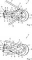
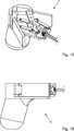
Die Steuervorrichtung
Die manuelle Steuervorrichtung
Die Steuervorrichtung
Der Daumenhebel
Der Verbindungshebel
Das Zentralelement
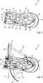
Die Steuervorrichtung
Der Verbindungshebel
Der erste Anlenkpunkt
Der erste Anlenkpunkt
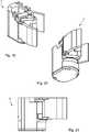
Es ist in der
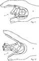
Die Steuervorrichtung
Das Zentralelement
Die in
Als Orientierungshilfe sind hier zudem eine Längsrichtung L der Steuervorrichtung
Zusätzlich ist eine Fingerbewegungsbahn
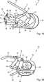
In
Es ist hier zu erkennen, dass die Breite der Steuervorrichtung
Der Signalgeber
Die Ausgestaltung der Handballenauflage
ZITATE ENTHALTEN IN DER BESCHREIBUNG QUOTES INCLUDE IN THE DESCRIPTION
Diese Liste der vom Anmelder aufgeführten Dokumente wurde automatisiert erzeugt und ist ausschließlich zur besseren Information des Lesers aufgenommen. Die Liste ist nicht Bestandteil der deutschen Patent- bzw. Gebrauchsmusteranmeldung. Das DPMA übernimmt keinerlei Haftung für etwaige Fehler oder Auslassungen.This list of the documents listed by the applicant has been generated automatically and is included solely for the better information of the reader. The list is not part of the German patent or utility model application. The DPMA assumes no liability for any errors or omissions.
Zitierte PatentliteraturCited patent literature
- US 6299624 B1[0005]US 6299624 B1[0005]
- US 2007/0005002 A1[0005]US 2007/0005002 Al[0005]
- US 2008/0154246 A1[0005]US 2008/0154246 A1[0005]
- US 5976121[0005]US 5976121[0005]
Claims (15)
Translated fromGermanPriority Applications (3)
| Application Number | Priority Date | Filing Date | Title |
|---|---|---|---|
| DE102014115600.5ADE102014115600A1 (en) | 2014-10-27 | 2014-10-27 | Surgical instrument with a manual control device |
| EP15190736.7AEP3015081B8 (en) | 2014-10-27 | 2015-10-21 | Surgical instrument with a manual control device |
| US14/923,006US10105127B2 (en) | 2014-10-27 | 2015-10-26 | Surgical instrument with a manual control |
Applications Claiming Priority (1)
| Application Number | Priority Date | Filing Date | Title |
|---|---|---|---|
| DE102014115600.5ADE102014115600A1 (en) | 2014-10-27 | 2014-10-27 | Surgical instrument with a manual control device |
Publications (1)
| Publication Number | Publication Date |
|---|---|
| DE102014115600A1true DE102014115600A1 (en) | 2016-04-28 |
Family
ID=54359953
Family Applications (1)
| Application Number | Title | Priority Date | Filing Date |
|---|---|---|---|
| DE102014115600.5AWithdrawnDE102014115600A1 (en) | 2014-10-27 | 2014-10-27 | Surgical instrument with a manual control device |
Country Status (3)
| Country | Link |
|---|---|
| US (1) | US10105127B2 (en) |
| EP (1) | EP3015081B8 (en) |
| DE (1) | DE102014115600A1 (en) |
Families Citing this family (7)
| Publication number | Priority date | Publication date | Assignee | Title |
|---|---|---|---|---|
| DE102012110260B4 (en)* | 2012-10-26 | 2018-10-11 | Karl Storz Se & Co. Kg | Operating handle for a microsurgical instrument |
| US11351001B2 (en) | 2015-08-17 | 2022-06-07 | Intuitive Surgical Operations, Inc. | Ungrounded master control devices and methods of use |
| US12419715B2 (en) | 2017-11-15 | 2025-09-23 | Intuitive Surgical Operations, Inc. | Master control device with multi-finger grip and methods therefor |
| WO2019099584A1 (en) | 2017-11-15 | 2019-05-23 | Intuitive Surgical Operations, Inc. | Master control device and methods therefor |
| NL2020421B1 (en) | 2018-02-12 | 2019-08-19 | Deam Holding B V | Surgical instrument with mechanically operable lever |
| US12329487B2 (en) | 2018-05-11 | 2025-06-17 | Intuitive Surgical Operations, Inc. | Master control device with finger grip sensing and methods therefor |
| GB202011106D0 (en)* | 2020-07-19 | 2020-09-02 | Imp College Innovations Ltd | Actuator handle for surgical tools, and improved surgical clips |
Citations (6)
| Publication number | Priority date | Publication date | Assignee | Title |
|---|---|---|---|---|
| EP0781112B1 (en)* | 1994-09-05 | 1998-12-23 | Klinikum Der Albert-Ludwigs-Universität Freiburg | Medical manipulator |
| US6299624B1 (en) | 1999-05-27 | 2001-10-09 | Karl Storz Gmbh & Co. Kg | Handle for a medical instrument |
| DE69430751T2 (en)* | 1993-10-01 | 2003-03-06 | Massachusetts Inst Technology | TACTILE INTERFACE WITH POWER RETURN |
| US20070005002A1 (en) | 2005-06-30 | 2007-01-04 | Intuitive Surgical Inc. | Robotic surgical instruments for irrigation, aspiration, and blowing |
| US20080154246A1 (en) | 1999-04-07 | 2008-06-26 | Intuitive Surgical, Inc. | Grip strength with tactile feedback for robotic surgery |
| US20130331826A1 (en)* | 2010-12-09 | 2013-12-12 | Agile Endosurgery, Inc. | Surgical instrument |
Family Cites Families (5)
| Publication number | Priority date | Publication date | Assignee | Title |
|---|---|---|---|---|
| GB2302655A (en)* | 1995-06-27 | 1997-01-29 | Mark Steven Whiteley | Hand-piece for laparoscopic instruments |
| DE19745157A1 (en)* | 1997-10-14 | 1999-06-10 | Storz Karl Gmbh & Co | Instrument or forceps for medical and especially endoscopic applications |
| US7410483B2 (en)* | 2003-05-23 | 2008-08-12 | Novare Surgical Systems, Inc. | Hand-actuated device for remote manipulation of a grasping tool |
| WO2012127404A2 (en)* | 2011-03-18 | 2012-09-27 | Ecole Polytechnique Federale De Lausanne (Epfl) | Ergonomic handle for haptic devices |
| JP6005950B2 (en)* | 2011-08-04 | 2016-10-12 | オリンパス株式会社 | Surgery support apparatus and control method thereof |
- 2014
- 2014-10-27DEDE102014115600.5Apatent/DE102014115600A1/ennot_activeWithdrawn
- 2015
- 2015-10-21EPEP15190736.7Apatent/EP3015081B8/enactiveActive
- 2015-10-26USUS14/923,006patent/US10105127B2/enactiveActive
Patent Citations (7)
| Publication number | Priority date | Publication date | Assignee | Title |
|---|---|---|---|---|
| DE69430751T2 (en)* | 1993-10-01 | 2003-03-06 | Massachusetts Inst Technology | TACTILE INTERFACE WITH POWER RETURN |
| US5976121A (en) | 1994-05-09 | 1999-11-02 | Karl Storz Gmbh & Co. | Medical manipulator |
| EP0781112B1 (en)* | 1994-09-05 | 1998-12-23 | Klinikum Der Albert-Ludwigs-Universität Freiburg | Medical manipulator |
| US20080154246A1 (en) | 1999-04-07 | 2008-06-26 | Intuitive Surgical, Inc. | Grip strength with tactile feedback for robotic surgery |
| US6299624B1 (en) | 1999-05-27 | 2001-10-09 | Karl Storz Gmbh & Co. Kg | Handle for a medical instrument |
| US20070005002A1 (en) | 2005-06-30 | 2007-01-04 | Intuitive Surgical Inc. | Robotic surgical instruments for irrigation, aspiration, and blowing |
| US20130331826A1 (en)* | 2010-12-09 | 2013-12-12 | Agile Endosurgery, Inc. | Surgical instrument |
Also Published As
| Publication number | Publication date |
|---|---|
| EP3015081B1 (en) | 2019-10-02 |
| US20160113637A1 (en) | 2016-04-28 |
| EP3015081B8 (en) | 2019-12-25 |
| US10105127B2 (en) | 2018-10-23 |
| EP3015081A1 (en) | 2016-05-04 |
Similar Documents
| Publication | Publication Date | Title |
|---|---|---|
| EP3015081B1 (en) | Surgical instrument with a manual control device | |
| DE3012447C2 (en) | Surgical grasper instrument | |
| DE69417349T2 (en) | IMPROVED HANDLE OF SURGICAL INSTRUMENTS | |
| DE10102089C1 (en) | Surgical instrument | |
| EP0901347B1 (en) | Instrument with a bendable handle | |
| DE10330604A1 (en) | Surgical instrument | |
| DE102011008013A1 (en) | Medical instrument | |
| DE102017010480A1 (en) | Medical instrument with plastic handles and a spring holder | |
| EP2491874B1 (en) | Surgical instrument with improved handling | |
| WO2005112795A1 (en) | Grip element for a surgical instrument | |
| DE202015105679U1 (en) | Adjusting means for a locking arrangement for adjusting a recorded on a furniture body movable furniture part | |
| EP1339332A1 (en) | Medical instrument | |
| WO2013000678A1 (en) | Surgical instrument | |
| DE202014102482U1 (en) | Device for moving a folded flap movably received on a furniture body and furniture with such a device | |
| DE102014001747A1 (en) | Construction machine, preferably bulldozer | |
| DE102014001390A1 (en) | Method for controlling a prosthesis | |
| EP1414357A1 (en) | Medical grasping and holding instrument | |
| DE29810958U1 (en) | Endoscopic shaft instrument | |
| DE102013013504A1 (en) | Endoscopic instrument | |
| DE102012014942A1 (en) | Bass mechanism for a hand-held instrument | |
| DE202016103085U1 (en) | Medical instrument | |
| DE202022103114U1 (en) | Pipetting device | |
| DE102022113873A1 (en) | Pipetting device | |
| DE102014111840A1 (en) | Eyeless instrument handle for a surgical tubular shaft instrument | |
| DE2309320B2 (en) | Rigid sliding roof for vehicles with brake rods that can be moved in the sliding direction |
Legal Events
| Date | Code | Title | Description |
|---|---|---|---|
| R081 | Change of applicant/patentee | Owner name:KARL STORZ SE & CO. KG, DE Free format text:FORMER OWNER: HOW TO ORGANIZE (H2O) GMBH, 10115 BERLIN, DE | |
| R082 | Change of representative | Representative=s name:WITTE, WELLER & PARTNER PATENTANWAELTE MBB, DE | |
| R163 | Identified publications notified | ||
| R081 | Change of applicant/patentee | Owner name:KARL STORZ SE & CO. KG, DE Free format text:FORMER OWNER: KARL STORZ GMBH & CO. KG, 78532 TUTTLINGEN, DE | |
| R082 | Change of representative | Representative=s name:WITTE, WELLER & PARTNER PATENTANWAELTE MBB, DE | |
| R005 | Application deemed withdrawn due to failure to request examination |