DE102014113658A1 - Device for repositioning bone fracture fragments - Google Patents
Device for repositioning bone fracture fragmentsDownload PDFInfo
- Publication number
- DE102014113658A1 DE102014113658A1DE102014113658.6ADE102014113658ADE102014113658A1DE 102014113658 A1DE102014113658 A1DE 102014113658A1DE 102014113658 ADE102014113658 ADE 102014113658ADE 102014113658 A1DE102014113658 A1DE 102014113658A1
- Authority
- DE
- Germany
- Prior art keywords
- arm
- unit
- contraption
- joint
- holding
- Prior art date
- Legal status (The legal status is an assumption and is not a legal conclusion. Google has not performed a legal analysis and makes no representation as to the accuracy of the status listed.)
- Withdrawn
Links
- 239000012634fragmentSubstances0.000titleclaimsabstractdescription58
- 208000010392Bone FracturesDiseases0.000titleclaimsabstractdescription47
- 210000000689upper legAnatomy0.000claimsdescription7
- 238000000034methodMethods0.000description14
- 206010017076FractureDiseases0.000description13
- 230000005540biological transmissionEffects0.000description11
- 210000003414extremityAnatomy0.000description11
- 230000008901benefitEffects0.000description7
- 210000000988bone and boneAnatomy0.000description7
- 239000012636effectorSubstances0.000description7
- 210000002414legAnatomy0.000description6
- 238000010276constructionMethods0.000description4
- 230000008569processEffects0.000description3
- 238000013519translationMethods0.000description3
- 230000001133accelerationEffects0.000description2
- 238000012937correctionMethods0.000description2
- 230000014759maintenance of locationEffects0.000description2
- 239000000463materialSubstances0.000description2
- 210000003205muscleAnatomy0.000description2
- 230000005855radiationEffects0.000description2
- 210000004872soft tissueAnatomy0.000description2
- 238000001356surgical procedureMethods0.000description2
- 238000002560therapeutic procedureMethods0.000description2
- 230000007704transitionEffects0.000description2
- BUHVIAUBTBOHAG-FOYDDCNASA-N(2r,3r,4s,5r)-2-[6-[[2-(3,5-dimethoxyphenyl)-2-(2-methylphenyl)ethyl]amino]purin-9-yl]-5-(hydroxymethyl)oxolane-3,4-diolChemical compoundCOC1=CC(OC)=CC(C(CNC=2C=3N=CN(C=3N=CN=2)[C@H]2[C@@H]([C@H](O)[C@@H](CO)O2)O)C=2C(=CC=CC=2)C)=C1BUHVIAUBTBOHAG-FOYDDCNASA-N0.000description1
- 206010061599Lower limb fractureDiseases0.000description1
- 208000028389Nerve injuryDiseases0.000description1
- 206010052428WoundDiseases0.000description1
- 208000027418Wounds and injuryDiseases0.000description1
- 230000008859changeEffects0.000description1
- 238000011109contaminationMethods0.000description1
- 230000008878couplingEffects0.000description1
- 238000010168coupling processMethods0.000description1
- 238000005859coupling reactionMethods0.000description1
- 230000001419dependent effectEffects0.000description1
- 238000011161developmentMethods0.000description1
- 230000018109developmental processEffects0.000description1
- 238000006073displacement reactionMethods0.000description1
- 210000001061foreheadAnatomy0.000description1
- 238000003384imaging methodMethods0.000description1
- 238000003780insertionMethods0.000description1
- 230000037431insertionEffects0.000description1
- 230000010354integrationEffects0.000description1
- 230000003902lesionEffects0.000description1
- 210000003141lower extremityAnatomy0.000description1
- 230000008764nerve damageEffects0.000description1
- 230000003287optical effectEffects0.000description1
- 210000002640perineumAnatomy0.000description1
- 238000007747platingMethods0.000description1
- 230000006641stabilisationEffects0.000description1
- 238000011105stabilizationMethods0.000description1
- 238000012549trainingMethods0.000description1
Images


Classifications
- A—HUMAN NECESSITIES
- A61—MEDICAL OR VETERINARY SCIENCE; HYGIENE
- A61G—TRANSPORT, PERSONAL CONVEYANCES, OR ACCOMMODATION SPECIALLY ADAPTED FOR PATIENTS OR DISABLED PERSONS; OPERATING TABLES OR CHAIRS; CHAIRS FOR DENTISTRY; FUNERAL DEVICES
- A61G13/00—Operating tables; Auxiliary appliances therefor
- A61G13/0036—Orthopaedic operating tables
- A—HUMAN NECESSITIES
- A61—MEDICAL OR VETERINARY SCIENCE; HYGIENE
- A61B—DIAGNOSIS; SURGERY; IDENTIFICATION
- A61B17/00—Surgical instruments, devices or methods
- A61B17/56—Surgical instruments or methods for treatment of bones or joints; Devices specially adapted therefor
- A61B17/58—Surgical instruments or methods for treatment of bones or joints; Devices specially adapted therefor for osteosynthesis, e.g. bone plates, screws or setting implements
- A61B17/60—Surgical instruments or methods for treatment of bones or joints; Devices specially adapted therefor for osteosynthesis, e.g. bone plates, screws or setting implements for external osteosynthesis, e.g. distractors, contractors
- A61B17/64—Devices extending alongside the bones to be positioned
- A—HUMAN NECESSITIES
- A61—MEDICAL OR VETERINARY SCIENCE; HYGIENE
- A61B—DIAGNOSIS; SURGERY; IDENTIFICATION
- A61B17/00—Surgical instruments, devices or methods
- A61B17/56—Surgical instruments or methods for treatment of bones or joints; Devices specially adapted therefor
- A61B17/58—Surgical instruments or methods for treatment of bones or joints; Devices specially adapted therefor for osteosynthesis, e.g. bone plates, screws or setting implements
- A61B17/60—Surgical instruments or methods for treatment of bones or joints; Devices specially adapted therefor for osteosynthesis, e.g. bone plates, screws or setting implements for external osteosynthesis, e.g. distractors, contractors
- A61B17/66—Alignment, compression or distraction mechanisms
- A—HUMAN NECESSITIES
- A61—MEDICAL OR VETERINARY SCIENCE; HYGIENE
- A61B—DIAGNOSIS; SURGERY; IDENTIFICATION
- A61B34/00—Computer-aided surgery; Manipulators or robots specially adapted for use in surgery
- A61B34/70—Manipulators specially adapted for use in surgery
- A—HUMAN NECESSITIES
- A61—MEDICAL OR VETERINARY SCIENCE; HYGIENE
- A61B—DIAGNOSIS; SURGERY; IDENTIFICATION
- A61B34/00—Computer-aided surgery; Manipulators or robots specially adapted for use in surgery
- A61B34/70—Manipulators specially adapted for use in surgery
- A61B34/74—Manipulators with manual electric input means
- A—HUMAN NECESSITIES
- A61—MEDICAL OR VETERINARY SCIENCE; HYGIENE
- A61B—DIAGNOSIS; SURGERY; IDENTIFICATION
- A61B90/00—Instruments, implements or accessories specially adapted for surgery or diagnosis and not covered by any of the groups A61B1/00 - A61B50/00, e.g. for luxation treatment or for protecting wound edges
- A61B90/50—Supports for surgical instruments, e.g. articulated arms
- A—HUMAN NECESSITIES
- A61—MEDICAL OR VETERINARY SCIENCE; HYGIENE
- A61G—TRANSPORT, PERSONAL CONVEYANCES, OR ACCOMMODATION SPECIALLY ADAPTED FOR PATIENTS OR DISABLED PERSONS; OPERATING TABLES OR CHAIRS; CHAIRS FOR DENTISTRY; FUNERAL DEVICES
- A61G13/00—Operating tables; Auxiliary appliances therefor
- A61G13/02—Adjustable operating tables; Controls therefor
- A61G13/08—Adjustable operating tables; Controls therefor the table being divided into different adjustable sections
- A—HUMAN NECESSITIES
- A61—MEDICAL OR VETERINARY SCIENCE; HYGIENE
- A61G—TRANSPORT, PERSONAL CONVEYANCES, OR ACCOMMODATION SPECIALLY ADAPTED FOR PATIENTS OR DISABLED PERSONS; OPERATING TABLES OR CHAIRS; CHAIRS FOR DENTISTRY; FUNERAL DEVICES
- A61G13/00—Operating tables; Auxiliary appliances therefor
- A61G13/10—Parts, details or accessories
- A61G13/12—Rests specially adapted therefor; Arrangements of patient-supporting surfaces
- A61G13/1205—Rests specially adapted therefor; Arrangements of patient-supporting surfaces for specific parts of the body
- A61G13/1245—Knees, upper or lower legs
- B—PERFORMING OPERATIONS; TRANSPORTING
- B25—HAND TOOLS; PORTABLE POWER-DRIVEN TOOLS; MANIPULATORS
- B25J—MANIPULATORS; CHAMBERS PROVIDED WITH MANIPULATION DEVICES
- B25J1/00—Manipulators positioned in space by hand
- B—PERFORMING OPERATIONS; TRANSPORTING
- B25—HAND TOOLS; PORTABLE POWER-DRIVEN TOOLS; MANIPULATORS
- B25J—MANIPULATORS; CHAMBERS PROVIDED WITH MANIPULATION DEVICES
- B25J13/00—Controls for manipulators
- B—PERFORMING OPERATIONS; TRANSPORTING
- B25—HAND TOOLS; PORTABLE POWER-DRIVEN TOOLS; MANIPULATORS
- B25J—MANIPULATORS; CHAMBERS PROVIDED WITH MANIPULATION DEVICES
- B25J9/00—Programme-controlled manipulators
- B25J9/0084—Programme-controlled manipulators comprising a plurality of manipulators
- B25J9/0087—Dual arms
- B—PERFORMING OPERATIONS; TRANSPORTING
- B25—HAND TOOLS; PORTABLE POWER-DRIVEN TOOLS; MANIPULATORS
- B25J—MANIPULATORS; CHAMBERS PROVIDED WITH MANIPULATION DEVICES
- B25J9/00—Programme-controlled manipulators
- B25J9/02—Programme-controlled manipulators characterised by movement of the arms, e.g. cartesian coordinate type
- B—PERFORMING OPERATIONS; TRANSPORTING
- B25—HAND TOOLS; PORTABLE POWER-DRIVEN TOOLS; MANIPULATORS
- B25J—MANIPULATORS; CHAMBERS PROVIDED WITH MANIPULATION DEVICES
- B25J9/00—Programme-controlled manipulators
- B25J9/10—Programme-controlled manipulators characterised by positioning means for manipulator elements
- B25J9/12—Programme-controlled manipulators characterised by positioning means for manipulator elements electric
- A—HUMAN NECESSITIES
- A61—MEDICAL OR VETERINARY SCIENCE; HYGIENE
- A61B—DIAGNOSIS; SURGERY; IDENTIFICATION
- A61B34/00—Computer-aided surgery; Manipulators or robots specially adapted for use in surgery
- A61B34/70—Manipulators specially adapted for use in surgery
- A61B34/74—Manipulators with manual electric input means
- A61B2034/742—Joysticks
Landscapes
- Health & Medical Sciences (AREA)
- Engineering & Computer Science (AREA)
- Life Sciences & Earth Sciences (AREA)
- Surgery (AREA)
- Orthopedic Medicine & Surgery (AREA)
- Public Health (AREA)
- General Health & Medical Sciences (AREA)
- Veterinary Medicine (AREA)
- Biomedical Technology (AREA)
- Animal Behavior & Ethology (AREA)
- Robotics (AREA)
- Molecular Biology (AREA)
- Medical Informatics (AREA)
- Heart & Thoracic Surgery (AREA)
- Nuclear Medicine, Radiotherapy & Molecular Imaging (AREA)
- Mechanical Engineering (AREA)
- Oral & Maxillofacial Surgery (AREA)
- Pathology (AREA)
- Surgical Instruments (AREA)
Abstract
Translated fromGermanDescription
Translated fromGermanDie Erfindung betrifft eine Vorrichtung zur Repositionierung von Knochenfrakturfragmenten, die eine Trägereinheit, einen an der Trägereinheit befestigten ersten Arm zum Halten eines ersten Knochenfrakturfragmentes und einen an der Trägereinheit befestigten zweiten Arm zum Halten eines zweiten Knochenfrakturfragmentes umfasst.The invention relates to a bone fracture fragment repositioning apparatus comprising a support unit, a first arm attached to the support unit for holding a first bone fracture fragment, and a second arm secured to the support unit for holding a second bone fracture fragment.
Die Fraktur der menschlichen Extremitäten ist meist auf ein Unfallgeschehen zurückzuführen. Die Repositionierung und Stabilisierung der Fragmente sind daher meist ungeplante chirurgische Eingriffe. Sofern der Zustand des Patienten, insbesondere der Kreislauf des Patienten, stabil ist wird der Operateur unter Zuhilfenahme verschiedener Hilfsmittel die Fraktur versorgen. Standardmäßig werden je nach Fraktur und Anzahl der Fragmente unterschiedliche/s Osteosynthesematerial und -verfahren verwendet. Es sind sowohl Platten als auch Markraumnägel üblich. Damit der Markraumnagel bzw. die Platte korrekt angebracht werden kann, müssen die Fragmente zueinander ausgerichtet bzw. repositioniert werden. Die Qualität der Ausrichtung ist entscheidend für das Ergebnis der Therapie und kann postoperativ nicht mehr verändert werden. Ausschließlich ein weiterer medizinischer Eingriff kommt zu Korrekturzwecken in Betracht. Da die Knochenfragmente immer innerhalb der Weichteile der Extremitäten liegen, können die Fragmente nur unter Zuhilfenahme von Röntgenbildverstärkern genau repositioniert werden. Erschwerend kommt hinzu, dass die den Knochen umgebenden Muskeln kontraktieren und so die Bruchstücke in einer unnatürlichen Ausrichtung zu liegen kommen.The fracture of the human extremities is usually due to an accident. The repositioning and stabilization of the fragments are therefore usually unplanned surgical procedures. If the condition of the patient, in particular the circulation of the patient, is stable, the surgeon will supply the fracture with the help of various aids. By default, different osteosynthesis material and procedures are used, depending on the fracture and the number of fragments. Both plates and medullary nails are common. In order for the intramedullary nail or the plate can be attached correctly, the fragments must be aligned or repositioned to each other. The quality of the alignment is crucial for the outcome of the therapy and can not be changed postoperatively. Only further medical intervention is considered for correction purposes. Since the bone fragments always lie within the soft tissues of the extremities, the fragments can only be repositioned accurately with the help of X-ray image intensifiers. To make matters worse, that contract the muscles surrounding the bone and so the fragments come to lie in an unnatural orientation.
Um die Fragmente korrekt auszurichten, müssen von außen auf die Fragmente Kräfte eingeleitet werden. Diese müssen für die Dauer der Verschraubung der Platten bzw. der Einbringung der Markraumnägel konstant gehalten werden.In order to align the fragments correctly, forces must be applied to the fragments from the outside. These must be kept constant for the duration of screwing the plates or the introduction of the intramedullary nails.
Eine ungenaue Ausrichtung der Fragmente führt zur recht großen rotativen Fehlorientierungen der Fragmente zueinander, welche postoperativ nicht mehr geändert werden können. Wegen des hohen Aufwandes und medizinischen Risikos eines Korrektureingriffes werden rotatorische Fehlstellungen in großem Umfang toleriert. Dies stellt eine suboptimale Versorgung des Patienten dar.An inaccurate alignment of the fragments leads to quite large rotative misorientations of the fragments to each other, which can not be changed postoperatively. Because of the high cost and medical risk of a corrective intervention rotatory misalignments are widely tolerated. This represents a sub-optimal care of the patient.
Eine erste Möglichkeit zum Ausrichten der Knochenfrakturfragmente ist es, dass ein Assistenzarzt damit beauftragt die Kräfte einzuleiten und die Fragmente durch Ziehen und Ausrichten des distalen Endes der Extremität zu repositionieren. Währenddessen richtet und befestigt der Operateur unter Zuhilfenahme eines Röntgenbildverstärkers das Osteosynthesematerial. Hierbei stehen der Assistenzarzt und der Operateur dauerhaft sehr nahe an der Röntgenquelle und sind erhöhter Strahlenbelastung ausgesetzt. Insbesondere durch ständige kleinere Bewegungen des Assistenzarztes muss das Röntgenbild stetig aktualisiert werden.One of the first ways to align the bone fracture fragments is to have an assistant physician set up the forces and reposition the fragments by pulling and aligning the distal end of the limb. Meanwhile, the surgeon straightens and fixes the osteosynthesis material with the aid of an X-ray image intensifier. The intern and the surgeon are permanently very close to the X-ray source and are exposed to increased radiation exposure. In particular, by constant minor movements of the assistant physician, the X-ray image must be constantly updated.
Problematisch hieran ist, dass die Ausrichtung der Knochen zueinander mit einem rotativen Fehler erfolgen kann, welcher intraoperativ nicht erkannt wird. Eine Fehlstellung von bis zu 15° wird daher als akzeptabel angesehen. Für den Patienten bedeutet dies beispielsweise eine Innenrotation bzw. Außenrotation des Fußes von bis zu 15°, was postoperativ zu Komplikationen bzw. erhöhtem Gelenkverschleiß führen kann.The problem with this is that the orientation of the bones to each other can be done with a rotative error, which is not recognized intraoperatively. A misalignment of up to 15 ° is therefore considered acceptable. For the patient, this means, for example, an internal rotation or external rotation of the foot of up to 15 °, which can lead to complications or increased joint wear postoperatively.
Bei der Fraktur der unteren Extremitäten bietet es sich auch an, den Patienten auf einem Extensionstisch zu lagern und die Distraktionskräfte über diesen auf den Patienten einzuleiten. Der Vorteil hierbei ist, dass die Repositionierung der Extremität wesentlich stabiler ist.In the fracture of the lower extremities, it is also advisable to store the patient on an extension table and to introduce the distraction forces on the patient. The advantage here is that the repositioning of the limb is much more stable.
Nachteilig ist, dass die präoperative Lagerung aufwändig ist und bei politraumatisierten Patienten teilweise kontraindiziert ist. Auch wurde von Nervenschädigungen und Weichteilläsionen im Perineum berichtet.The disadvantage is that the preoperative storage is complex and partially contraindicated in politraumatisierten patients. Nerve damage and soft tissue lesions in the perineum have also been reported.
Eine weitere Möglichkeit ist die Verwendung von mechanischem Fixateur Externe. Hierbei handelt es sich um eine mechanische Vorrichtung, bei der die Fragmente mittels Schanzschen Schrauben/Kirschnerdrähte über extrakorporale Stangen zueinander fixiert sind. Es sind Systeme bekannt, bei denen die Stangen mittels Spindeln eingestellt werden können.Another possibility is the use of external mechanical fixator. This is a mechanical device in which the fragments are fixed to each other via extracorporeal rods by means of Schanz screws / Kirschner wires. Systems are known in which the rods can be adjusted by means of spindles.
Eine weitere Möglichkeit ist die Verwendung von robotischen Assistenzsystemen. Hierbei wird meist das distale Fragment der Frakturfragmente über geeignete Befestigungs- und oder Greifersysteme gegenüber den proximalen Fragment mittels eines robotischen Systems positioniert. Nachteilig hieran ist, dass dies ein sehr zeitaufwändiges Vorgehen ist, da die Roboter sowie ein entsprechendes optisches Navigationssystem initialisiert und registriert werden müssen. Meistens benötigt man für diese Prozesse 3D Röntgenbildaufnahmen wie sie nur mittels der CT angefertigt werden können. Eine solche Technik kann also nur dann eingesetzt werden, wenn 3D Röntgenaufnahmen mit Referenzkörpern zur Verfügung stehen, die Spezialisten, welche die Anlagen sicher bedienen können, vor Ort sind und der Zustand des Patienten nicht gefährdet bzw. stabil ist.Another possibility is the use of robotic assistance systems. In this case, the distal fragment of the fracture fragments is usually positioned by means of a robotic system via suitable fastening and / or gripper systems in relation to the proximal fragment. The disadvantage of this is that this is a very time-consuming procedure, since the robot and a corresponding optical navigation system must be initialized and registered. In most cases, 3D x-ray images are required for these processes, as they can only be made using CT. Such a technique can therefore only be used if 3D X-ray images with reference bodies are available, the specialists who can operate the equipment safely are on site and the condition of the patient is not endangered or stable.
Es ist Aufgabe der Erfindung, eine Vorrichtung zur Repositionierung von Knochenfrakturfragmenten anzugeben, mit deren Hilfe auf einfache Weise eine genaue Repositionierung der Knochenfrakturfragmente möglich ist.It is an object of the invention to provide a device for repositioning bone fracture fragments, with the help of a simple way, an accurate repositioning of the bone fracture fragments is possible.
Diese Aufgabe wird durch eine Vorrichtung mit den Merkmalen des Anspruchs 1 gelöst. Vorteilhafte Weiterbildungen der Erfindung sind in den abhängigen Ansprüchen angegeben. This object is achieved by a device having the features of claim 1. Advantageous developments of the invention are specified in the dependent claims.
Erfindungsgemäß weist die Vorrichtung eine elektrische Antriebseinheit zum Verstellen des zweiten Arms auf. Ferner hat die Vorrichtung ein Betätigungselement zum Steuern der Verstellung des zweiten Arms über diese elektrische Antriebseinheit.According to the invention, the device has an electric drive unit for adjusting the second arm. Furthermore, the device has an actuating element for controlling the adjustment of the second arm via this electric drive unit.
Hierdurch wird erreicht, dass die Repositionierung der Knochenfrakturfragmente relativ zueinander auf einfache Weise über die Vorrichtung automatisch ausgeführt werden kann. Hierzu wird das erste Knochenfrakturfragment an dem ersten Arm befestigt und das zweite Knochenfrakturfragment an einem zweiten Arm. Anschließend wird das zweite Knochenfrakturfragment über die Antriebseinheit mit Hilfe der Betätigungseinheit motorisch in die gewünschte Position verfahren.This ensures that the repositioning of the bone fracture fragments relative to each other can be carried out automatically via the device in a simple manner. For this, the first bone fracture fragment is attached to the first arm and the second bone fracture fragment to a second arm. Subsequently, the second bone fracture fragment is moved via the drive unit by means of the actuating unit by motor to the desired position.
Dies hat den Vorteil, dass die zur Repositionierung notwendigen Kräfte nicht manuell aufgebracht werden müssen, wodurch eine wesentlich genauere Repositionierung erfolgen kann und somit Fehlstellungen vermieden werden. Darüber hinaus muss sich keine Person während der Repositionierung im Röntgenbereich aufhalten.This has the advantage that the forces necessary for repositioning need not be applied manually, whereby a much more accurate repositioning can be done and thus misalignments are avoided. In addition, no person must be in the X-ray area during the repositioning.
Gegenüber robotischen Systemen hat die Vorrichtung den Vorteil, dass sie wesentlich einfacher und kompakter aufgebaut ist.Compared to robotic systems, the device has the advantage that it is much simpler and more compact.
Bei einer besonders bevorzugten Ausführungsform ist an dem der Trägereinheit abgewandten Ende des ersten Arms eine erste Halteeinheit zum Halten von Schanzschen Schrauben und/oder an dem der Trägereinheit abgewandten Ende des zweiten Arms eine zweite Einheit zum Halten von Schanzschen Schrauben vorgesehen. Auf diese Weise können die Schanzschen Schrauben, die in die Knochenfrakturfragmente zuvor eingebracht wurden, auf einfache Weise an den Armen befestigt werden, so dass dann über die Ausrichtung der Arme relativ zueinander die über die Schanzschen Schrauben gehaltenen Knochenfrakturfragmente in die gewünschte Position gebracht werden.In a particularly preferred embodiment, a first holding unit for holding Schanz screws and / or at the end remote from the carrier unit end of the second arm, a second unit for holding Schanz screws is provided at the end remote from the carrier unit of the first arm. In this way, the Schanz screws, which were previously introduced into the bone fracture fragments, can be attached to the arms in a simple manner, so that the orientation of the arms relative to one another brings the bone fracture fragments held via the Schanz screws to the desired position.
Es ist besonders vorteilhaft, wenn mit Hilfe der Antriebseinheit der zweite Arm derart verstellbar ist, dass die Position der zweiten Antriebseinheit relativ zur Trägereinheit beliebig verstellbar ist, d. h. in möglichst alle Richtungen verstellbar ist.It is particularly advantageous if with the aid of the drive unit, the second arm is adjustable so that the position of the second drive unit relative to the carrier unit is arbitrarily adjustable, d. H. is adjustable in as many directions as possible.
Der zweite Arm ist hierzu mit Hilfe der Antriebseinheit insbesondere derart in seiner Position und Ausrichtung verstellbar, dass die zweite Halteeinheit um alle sechs Freiheitsgrade des dreidimensionalen Raums verstellbar ist. Somit kann die zweite Halteeinheit insbesondere entlang dreier orthogonal zueinander stehenden Achsen bewegt und um alle drei Achsen ebenfalls gedreht werden. Hierdurch wird erreicht, dass eine beliebige Ausrichtbarkeit der Knochenfrakturfragmente möglich ist, so dass jede notwendige Position eingestellt werden kann.For this purpose, the second arm can be adjusted in terms of its position and orientation, in particular with the aid of the drive unit, such that the second holding unit can be adjusted by all six degrees of freedom of the three-dimensional space. Thus, the second holding unit can be moved in particular along three orthogonal axes and also rotated about all three axes. This ensures that any alignability of bone fracture fragments is possible, so that any necessary position can be adjusted.
Ferner umfasst die Trägereinheit insbesondere eine Befestigungseinheit zum Befestigen der Vorrichtung an einem Operationstisch. Dies hat den Vorteil, dass die Vorrichtung immer dann, wenn sie gebraucht wird, an dem entsprechenden Operationstisch angebracht werden kann. Die Befestigungseinheit ist insbesondere derart ausgebildet, dass eine reibschlüssige Verbindung erfolgt, so dass auch beim Ändern der Position des Patienten die Kräfte in etwa konstant bleiben.In addition, the carrier unit in particular comprises a fastening unit for fastening the device to an operating table. This has the advantage that the device can be attached to the corresponding operating table whenever it is needed. The fastening unit is in particular designed such that a frictional connection takes place, so that the forces remain approximately constant even when changing the position of the patient.
Darüber hinaus ist die Befestigungseinheit insbesondere derart ausgebildet, dass sie ein Gelenk aufweist, durch das die Vorrichtung relativ zum Operationstisch um mindestens eine Achse gedreht werden kann, so dass insbesondere die Beine entsprechend abgespreizt werden können.In addition, the fastening unit is in particular designed such that it has a joint through which the device can be rotated relative to the operating table about at least one axis, so that in particular the legs can be spread apart accordingly.
Die Befestigungseinheit ist insbesondere derart ausgebildet, dass die Vorrichtung an standardmäßigen Schnittstellen zur Aufnahme von Beinplatten angebracht werden kann.The fastening unit is in particular designed such that the device can be attached to standard interfaces for receiving leg panels.
Bei einer besonders bevorzugten Ausführungsform umfasst der erste Arm mindestens ein manuell verstellbares Gelenk. Vorzugsweise sind mehrere manuell verstellbare Gelenke vorgesehen. Hierdurch wird erreicht, dass auch die Position und Ausrichtung der ersten Halteeinheit verändert werden kann, so dass die notwendige Positionierung des ersten Knochenfrakturfragmentes erfolgen kann. Insbesondere sind manuell betätigbare Feststelleinheiten zum Feststellen der Gelenke des ersten Arms an den Gelenken vorgesehen, so dass nach dem manuellen Ausrichten des ersten Arms dieser in der gewünschten Position fixiert werden kann.In a particularly preferred embodiment, the first arm comprises at least one manually adjustable joint. Preferably, several manually adjustable joints are provided. This ensures that the position and orientation of the first holding unit can be changed, so that the necessary positioning of the first bone fracture fragment can be done. In particular, manually operable locking units are provided for locking the hinges of the first arm to the joints so that after manual alignment of the first arm, it can be fixed in the desired position.
Der erste Arm ist somit insbesondere rein manuell verstellbar. Bei einer alternativen Ausführungsform der Erfindung kann auch eine weitere elektrische Antriebseinheit, insbesondere ein Motor oder mehrere Motoren, für das Verstellen des ersten Arms vorgesehen sein.The first arm is thus in particular purely manually adjustable. In an alternative embodiment of the invention, a further electric drive unit, in particular a motor or a plurality of motors, may be provided for adjusting the first arm.
Das Gelenk bzw. die Gelenke des ersten Arms sind insbesondere derart ausgebildet, dass die erste Halteeinheit um sechs Freiheitsgrade verstellt werden kann.The joint or joints of the first arm are in particular designed such that the first holding unit can be adjusted by six degrees of freedom.
Bei dem ersten Arm kann es sich insbesondere um einen Arm handeln, wie dieser in dem Patent
Ferner ist es vorteilhaft, wenn die Trägereinheit eine Schiene umfasst und wenn der zweite Arm einen Schlitten umfasst, der auf der Schiene in Richtung der Längsachse der Schiene verfahrbar gelagert ist. Das Verfahren des Schlittens und somit des zweiten Armes auf der Schiene erfolgt insbesondere mit Hilfe der elektrischen Antriebseinheit.Furthermore, it is advantageous if the carrier unit comprises a rail and if the second arm comprises a carriage which is movably mounted on the rail in the direction of the longitudinal axis of the rail. The method of the carriage and thus the second arm on the rail takes place in particular by means of the electric drive unit.
Die elektrische Antriebseinheit weist hierzu insbesondere einen ersten Motor auf, der mit einer Spindel in Eingriff ist, über die der Schlitten entlang der Schiene verfahren werden kann.For this purpose, the electric drive unit has, in particular, a first motor, which is in engagement with a spindle, via which the carriage can be moved along the rail.
Bei einer besonders bevorzugten Ausführungsform der Erfindung umfasst auch der zweite Arm mehrere Gelenke, wobei insbesondere jedem Gelenk ein Motor zum Verstellen des Gelenkes zugeordnet ist. Insbesondere sind diese Motoren der elektrischen Antriebseinheit jeweils unmittelbar an dem Gelenk angeordnet, so dass keine aufwändigen Kraftübertragungen über größere Strecken notwendig ist, was zu einer Fehleranfälligkeit führen würde und verschmutzungsanfällig wäre.In a particularly preferred embodiment of the invention, the second arm also comprises a plurality of joints, wherein in particular each joint is associated with a motor for adjusting the joint. In particular, these motors of the electric drive unit are each arranged directly on the joint, so that no costly power transmission over long distances is necessary, which would lead to a susceptibility to error and would be susceptible to contamination.
Bei einer besonders bevorzugten Ausführungsform der Erfindung weist der zweite Arm ein erstes, ein zweites sowie ein drittes Gelenk auf. Ferner hat der zweite Arm mindestens zwei Verbindungsplatten. Das erste Gelenk verbindet die erste Verbindungsplatte gelenkig mit dem Schlitten. Die erste Verbindungsplatte ist zwischen dem ersten und dem zweiten Gelenk angeordnet, wobei das zweite Gelenk die erste und die zweite Verbindungsplatte gelenkig miteinander verbindet. An dem dem zweiten Gelenk abgewandten Ende der zweiten Verbindungsplatte ist das dritte Gelenk angeordnet, an dem insbesondere wiederum die zweite Halteeinheit befestigt ist.In a particularly preferred embodiment of the invention, the second arm has a first, a second and a third joint. Furthermore, the second arm has at least two connecting plates. The first joint articulates the first connection plate to the carriage. The first connection plate is disposed between the first and second hinges, the second hinge hingedly interconnecting the first and second connection plates. At the end remote from the second joint end of the second connecting plate, the third joint is arranged, on which in turn in turn the second holding unit is attached.
Auf diese Weise wird auf besonders einfache und kompakte Art ein robuster Arm geschaffen, der motorisch verstellbar ist und ein Bewegen der zweiten Halteeinheit und somit des zweiten Knochenfrakturfragmentes in alle sechs Freiheitsgrade des dreidimensionalen Raumes ermöglicht.In this way, a robust arm is created in a particularly simple and compact manner, which is adjustable by motor and allows movement of the second holding unit and thus the second bone fracture fragment in all six degrees of freedom of the three-dimensional space.
Die die Betätigungseinheit ansteuernde elektrische Antriebseinheit zum Verstellen des zweiten Haltearmes ist insbesondere im Bereich des dritten Gelenkes angeordnet und befindet sich somit insbesondere an dem der Trägereinheit abgewandten Ende des zweiten Armes.The actuating unit driving the electric drive unit for adjusting the second holding arm is arranged in particular in the region of the third joint and is thus located in particular at the end remote from the carrier unit of the second arm.
Die Betätigungseinheit ist hierbei insbesondere derart ausgebildet, dass bei ihrer Betätigung in eine vorbestimmte Richtung der zweite Arm entsprechend in diese Richtung bewegt bzw. gedreht wird. Durch die Befestigung am Ende des zweiten Armes wird somit eine intuitive Steuerung erreicht, d. h. dass die Bedienperson das Betätigungselement einfach nur so bewegen muss, wie auch der zweite Arm bewegt werden soll. Somit ist eine genaue präzise Verstellung des zweiten Armes ohne aufwändige Einweisungen und Erfahrungen möglich.The actuating unit is in this case designed in particular such that, when actuated in a predetermined direction, the second arm is moved or rotated accordingly in this direction. The attachment at the end of the second arm thus achieves intuitive control, i. H. that the operator simply has to move the actuator just as the second arm is to be moved. Thus, a precise precise adjustment of the second arm without time-consuming instructions and experience is possible.
Ferner ist vorteilhaft, wenn das erste Gelenk ein einwertiges Gelenk ist, d. h. dass das erste Gelenk ausschließlich eine Drehung um eine erste Drehachse erlaubt. Auch das zweite Gelenk ist einwertig und erlaub somit eine Drehung um eine zweite Drehachse. Es ist besonders vorteilhaft, wenn die erste und die zweite Drehachse parallel zueinander verlaufen.Furthermore, it is advantageous if the first joint is a monovalent joint, i. H. that the first joint only allows rotation about a first axis of rotation. Also, the second joint is monovalent and thus allows rotation about a second axis of rotation. It is particularly advantageous if the first and the second axis of rotation run parallel to one another.
Das dritte Gelenk ist insbesondere derart ausgebildet, dass es eine Verdrehung um drei orthogonal zueinander angeordnete Drehachsen ermöglicht. Eine dieser drei Drehachsen ist insbesondere parallel zur ersten und der zweiten Drehachse ausgerichtet. Somit wird über diese drei einfach und stabil aufgebauten Gelenke ein Verstellen in fünf Freiheitsgraden ermöglicht. Der sechste Freiheitsgrad wird durch das Verfahren des Schlittens und somit des zweiten Armes auf der Schiene ermöglicht.The third joint is in particular designed such that it allows a rotation about three mutually orthogonal axes of rotation. One of these three axes of rotation is aligned in particular parallel to the first and the second axis of rotation. Thus, an adjustment in five degrees of freedom is made possible by these three simple and stable joints. The sixth degree of freedom is made possible by moving the carriage and thus the second arm on the rail.
Ferner ist es vorteilhaft, wenn das Betätigungselement einen Joystick umfasst, der ein einfaches und intuitives Bedienen ermöglicht. Das Betätigungselement weist insbesondere selbst sechs Freiheitsgrade auf, so dass bei einer Betätigung des Betätigungselementes um einen dieser Freiheitsgrade der Arm das Knochenfrakturfragment ebenfalls entsprechend um diesen Freiheitsgrad bewegt bzw. dreht. Als Betätigungselement ist somit insbesondere ein sogenannter 6 DoF Sensor vorgesehen, durch den Bedieneingaben zur Ansteuerung von insgesamt sechs Freiheitsgraden einfach möglich sind.Furthermore, it is advantageous if the actuating element comprises a joystick, which allows a simple and intuitive operation. In particular, the actuating element itself has six degrees of freedom, so that upon actuation of the actuating element by one of these degrees of freedom, the arm likewise moves or rotates the bone fracture fragment by this degree of freedom. Thus, in particular a so-called 6 DoF sensor is provided as an actuating element, by means of which operating inputs for triggering a total of six degrees of freedom are simply possible.
Ferner ist es vorteilhaft, wenn an der Trägereinheit ein Oberschenkelpolster zur Auflage eines Oberschenkels und/oder einer Unterschenkelpolster zur Auflage des Unterschenkels befestigt ist. Insbesondere sind die Befestigungen der Polster derart ausgebildet, dass die Polster abnehmbar sind. Somit kann je nach durchzuführendem Operationsschritt, beispielsweise das Einfügen eines Markraumnagels, die notwendige Abstützung des gebrochenen Beines erfolgen oder der notwendige Zugriff auf das Bein sichergestellt sein.Furthermore, it is advantageous if a thigh pad for supporting a thigh and / or a lower leg pad to support the lower leg is attached to the support unit. In particular, the attachments of the pads are formed such that the pads are removable. Thus, depending on the operation to be performed, for example, the insertion of a medullary nail, the necessary support of the broken leg can be made or the necessary access to the leg can be ensured.
Ein weiterer Aspekt der Erfindung betrifft einen Operationstisch, wobei an diesem Operationstisch mindestens eine Vorrichtung der zuvor genannten Art abnehmbar befestigt ist. Es ist besonders vorteilhaft, wenn die Vorrichtung über eine reibschlüssige Befestigung an dem Operationstisch befestigt ist.Another aspect of the invention relates to an operating table, wherein on this operating table at least one device previously mentioned type is detachably attached. It is particularly advantageous if the device is attached via a frictional attachment to the operating table.
Weitere Merkmale und Vorteile der Erfindung ergeben sich aus der folgenden Beschreibung, die die Erfindung anhand von Ausführungsbeispielen in Zusammenhang mit den beigefügten Figuren näher erläutert.Further features and advantages of the invention will become apparent from the following description, which illustrates the invention with reference to embodiments in conjunction with the accompanying figures.
Es zeigen:Show it:
In den
Bei einer Fraktur von menschlichen Knochen, insbesondere von großen Hohlknochen, müssen die Fragmente zueinander ausgerichtet bzw. repositioniert werden. Erst nachdem dies geschehen ist, können die einzelnen Knochenfragmente über Platten und/oder Markraumnägel fixiert werden.In a fracture of human bones, especially of large hollow bones, the fragments must be aligned with each other or repositioned. Only after this has happened can the individual bone fragments be fixed by means of plates and / or medullary nails.
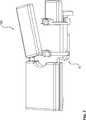
Die Vorrichtung
Hierbei werden zunächst die Schanzschen Schrauben eines ersten Knochenfrakturfragmentes an dem ersten Arm
Anschließend wird das zweite Knochenfrakturfragment über Schanzsche Schrauben an der zweiten Halteeinheit
Auch der zweite Arm
Das erste Gelenk
Ferner ist an dem zweiten Gelenk
Das dritte Gelenk
Die Drehachsen
Durch den zuvor beschriebenen Aufbau wird erreicht, dass alleine schon durch die drei Gelenke
Um auch noch ein Verstellen um den verbleibenden sechsten Freiheitsgrad zu ermöglichen, ist das der zweiten Halteeinheit
Sowohl das Verfahren des zweiten Arms
Bei anderen Ausführungsbeispielen können auch das erste Gelenk
Die Vorrichtung
Ferner ist an dem Ende des zweiten Armes
Bei dem Betätigungselement
Die Kappe des Betätigungselementes
Je nachdem, welche Versorgung der Fraktur erfolgt, ist eine unterschiedliche Lagerung der gebrochenen Extremität vor, während und nach der Operation notwendig. Um dies zu gewährleisten können an der Trägereinheit
Bei der in
Die Vorrichtung
Wie den
In den
In den
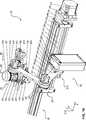
Grundbestandteil der Vorrichtung ist eine Linearfahrbahn. Ausgerichtet ist sie mit ihrer Hauptachse entlang der X-Achse des Koordinatensystems der Vorrichtung
Die Fahrbahn besteht aus einer Tragekonstruktion
Auf dem Schlitten
Auf dem beweglichen Schlitten ist eine Grundplatte angebracht und senkrecht dazu eine Basisplatte
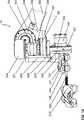
An der Oberseite der Platte
An diese ist im rechten Winkel auf der Seite des Getriebes
Unterhalb der Getriebes
Am Abtriebskranz des zuletzt genannten Getriebes ist eine Aufnahmeplatte
Beide Schanzschen Schrauben sind im distalen Femurfragment
Zur Aufnahme des Grundgestänges verfügt die Vorrichtung
Mittels eines Übergangsstückes
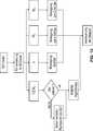
Wünscht der Nutzer eine Translation der Pinhalterung in positiver X-Richtung, schiebt er das Betätigungselement
Zur Ansteuerung der Motoren
Wenn der Nutzer während der Bewegung des Systems weiterhin seine Eingabe aufrecht erhält, wird der Beginn der Verzögerungsrampe neu berechnet und entsprechend später gestartet, sollte diese noch nicht erreicht worden sein. Befindet sich das System bereits in der Verzögerungsphase wird eine Beschleunigungsrampe berechnet, welche zum Erreichen der Maximalgeschwindigkeit mit definierter Steigung notwendig ist, und ausgeführt. Beendet der Nutzer seine Eingabe wird die zuvor berechnete Bewegungstrajektorie bis zu Ende abgefahren. Danach wird die erreichte Positionierung permanent gehalten. Analog wird mit der Änderung der Ausrichtung des Endeffektors verfahren. Hierbei führt der Nutzer eine Drehung der Kappe
Handelt es sich jedoch um eine Drehung um die X-Achse – benannt mit Mx – wird, insbesondere mittels des FABRIK Algorithmus, eine neue Konfiguration der Winkelstellungen des Gelenkarms berechnet. Anschließend wird die Ansteuerung der beteiligten Gelenke wie beschrieben durchgeführt. Nach Abschluss des Verfahrens wird wiederum die Ausrichtung und Position des Endeffektors ohne Nutzereingabe permanent gehalten.However, if it is a rotation about the X-axis - named Mx - a new configuration of the articulated arm angular positions is calculated, in particular by means of the FABRIK algorithm. Subsequently, the control of the joints involved is performed as described. After completing the procedure, the orientation and position of the end effector without user input is again permanently held.
Die vorgesehene intraoperative Verwendung der Vorrichtung
Die Vorrichtung
Ist eine spielfreie mechanische Klemmverbindung hergestellt worden, kann der Operateur einzelne Gelenke des passiven Arms lösen und das proximale Fragment neu ausrichten. Nach zufriedenstellender Ausrichtung wird der Arm komplett fixiert. Die so erzeugte Retention der Position und Orientierung des proximalen Fragments dient als Referenz zur Ausrichtung und Positionierung des distalen Fragments. Dazu verwendet der Operateur den motorisierten Gelenkarm und verändert die Ausrichtung und Position des Endeffektors durch Einwirken auf die Sensorkappe mittels der darauf aufgelegten Hand. Nach zufriedenstellender Ausrichtung lässt der Operateur den Sensor los. Die Vorrichtung hält nun die eingestellte Position und Orientierung konstant. Der Operateur kann sich mittels Röntgenbildgebung von der Qualität seiner Repositionierung überzeugen. Dazu kann das gesamte OP Team zum Schutz vor Strahlungsapplikation eine gewisse Distanz zum Strahlenbündel einnehmen. Nach Auswertung der erzeugten Bilder können Korrekturen durch erneutes Positionieren durchgeführt werden. Nach Abschluss der Reponierung kann der Führungsdraht eingebracht und ggf. der Markraum aufgebohrt werden. Wird unaufgebohrt und ohne Führungsdraht genagelt, kann an dieser Stelle der Nagel eingebracht werden. Nachdem der Nagel den Frakturspalt passiert hat, muss die Vorrichtung entfernt werden. Dazu wird in umgekehrter Reihenfolge zum Anlegen der Vorrichtung vorgegangen. Zunächst müssen die Klemmverbingungen mit der Vorrichtung mit dem Fixateur externe gelöst werden, anschließend die Schanzschen Schrauben entfernt werden. Abschließend wird der Eingriff konventionell beendet, indem der Nagel auf konventionelle Weise vollends eingebracht, verriegelt, die Verschlusskappe eingesetzt – falls gewünscht – und alle Wunden verschlossen werden.If a backlash-free mechanical clamping connection has been made, the surgeon can loosen individual joints of the passive arm and realign the proximal fragment. After satisfactory alignment, the arm is completely fixed. The retention of the position and orientation of the proximal fragment thus created serves as a reference for the orientation and positioning of the distal fragment. For this purpose, the surgeon uses the motorized articulated arm and changes the orientation and position of the end effector by acting on the sensor cap by means of the hand placed thereon. After satisfactory alignment, the surgeon releases the sensor. The device now keeps the set position and orientation constant. The surgeon can convince himself of the quality of his repositioning by means of X-ray imaging. For this purpose, the entire OR team can take a certain distance from the radiation beam to protect against radiation application. After evaluating the generated images, corrections can be made by repositioning. After completion of the repositioning, the guide wire can be inserted and, if necessary, the medullary canal drilled. If undrilled and nailed without guidewire, the nail can be inserted at this point. After the nail has passed the fracture gap, the device must be removed. This is done in reverse order to create the device. First, the clamping conditions must be solved with the device with the external fixer, then the Schanz screws are removed. Finally, the procedure is terminated conventionally by fully inserting the nail in a conventional manner, locking it, inserting the cap - if desired - and closing all wounds.
Bei einer Verplattung der Fragmente bleibt die Vorrichtung während diesem Abschnitt der Therapie montiert.Plating the fragments will leave the device mounted during this portion of the therapy.
Durch die zuvor beschriebene Vorrichtung wird insbesondere eine Erhöhung der Präzision der Positionierung des Knochens erreicht.By the device described above, in particular an increase in the precision of the positioning of the bone is achieved.
Ferner wird die Notwendigkeit des Verbleibes von Körperteilen des Operateurs im Strahlengang eines Röntgengerätes während des Belichtungsvorgangs der Röntgenbilder vermieden.Furthermore, the necessity of the stay of body parts of the surgeon in the beam path of an X-ray machine during the exposure process of the X-ray images is avoided.
Darüber hinaus wird eine intuitive Steuerung des beschriebenen Systems durch den Operateur erreicht.In addition, an intuitive control of the system described by the surgeon is achieved.
Im Vergleich zu anderen robotischen Systemen, welche durch fest im Raum befestigte Joysticks angesteuert werden, ist hier die Besonderheit, dass der Sensor direkt am Endeffektor angebracht ist. Hieraus ergibt sich folgendes Szenario: Der Chirurg bzw. der assistierende Arzt umfasst mit einer Hand den Bereich der Extremität der Distal von der Fraktur ist und umfasst mit der anderen Hand das Sensorelement, welcher sehr nahe an der Extremität angeordnet ist und keine Relativbewegung zur Extremität erfährt. Dadurch kann der Arzt den Bereich der Extremität so bewegen, wie er es auch ohne Vorrichtung durchführen würde. Dieses Vorgehen ist sehr intuitiv und benötigt keine lange Einlernzeit. Ein weiterer Vorteil ist, dass der Arzt der immer eine Hand an der Extremität hat und so permanent ein haptisches Feedback erfährt, so wie er es von der rein manuellen Repositionierung auch erfahren würde mit dem Vorteil, dass er keine hohen Zugkräfte auf die Extremität aufprägen muss. Durch die Entkopplung der hohen Zugkräfte, welche durch die Muskeln der Patienten erzeugt werden, kann auch sehr feinfühlig und präzise gearbeitet werden, was mit einem besseren Ergebnis einhergeht.Compared to other robotic systems, which are controlled by fixed joysticks in the room, here is the special feature that the sensor is attached directly to the end effector. This results in the following scenario: The surgeon or the assisting physician comprises with one hand the area of the extremity of the distal of the fracture and includes with the other hand, the sensor element which is located very close to the extremity and does not experience relative movement to the extremity , This allows the physician to move the limb as he would without a device. This procedure is very intuitive and does not require a long training period. Another advantage is that the doctor, who always has a hand on the extremity and thus permanently receives haptic feedback, as he would also learn from purely manual repositioning with the advantage that he must not impose high tensile forces on the limb , By decoupling the high tensile forces generated by the muscles of the patient, it is also possible to work very sensitively and precisely, which results in a better result.
Darüber hinaus ist die Vorrichtung
Im Vergleich zu robotischen Systemen benötigt die Vorrichtung
ZITATE ENTHALTEN IN DER BESCHREIBUNG QUOTES INCLUDE IN THE DESCRIPTION
Diese Liste der vom Anmelder aufgeführten Dokumente wurde automatisiert erzeugt und ist ausschließlich zur besseren Information des Lesers aufgenommen. Die Liste ist nicht Bestandteil der deutschen Patent- bzw. Gebrauchsmusteranmeldung. Das DPMA übernimmt keinerlei Haftung für etwaige Fehler oder Auslassungen.This list of the documents listed by the applicant has been generated automatically and is included solely for the better information of the reader. The list is not part of the German patent or utility model application. The DPMA assumes no liability for any errors or omissions.
Zitierte PatentliteraturCited patent literature
- DE 10209209 B4[0026, 0026]DE 10209209 B4[0026, 0026]
- DE 102012112716 A1[0026, 0026]DE 102012112716 A1[0026, 0026]
Claims (22)
Translated fromGermanPriority Applications (5)
| Application Number | Priority Date | Filing Date | Title |
|---|---|---|---|
| DE102014113658.6ADE102014113658A1 (en) | 2014-09-22 | 2014-09-22 | Device for repositioning bone fracture fragments |
| EP15766484.8AEP3197379B1 (en) | 2014-09-22 | 2015-09-18 | Device for repositioning bone fracture fragments |
| PCT/EP2015/071489WO2016046089A1 (en) | 2014-09-22 | 2015-09-18 | Device for repositioning bone fracture fragments |
| PL15766484TPL3197379T3 (en) | 2014-09-22 | 2015-09-18 | Device for repositioning bone fracture fragments |
| US15/442,878US10478362B2 (en) | 2014-09-22 | 2017-02-27 | Device for repositioning bone fracture fragments |
Applications Claiming Priority (1)
| Application Number | Priority Date | Filing Date | Title |
|---|---|---|---|
| DE102014113658.6ADE102014113658A1 (en) | 2014-09-22 | 2014-09-22 | Device for repositioning bone fracture fragments |
Publications (1)
| Publication Number | Publication Date |
|---|---|
| DE102014113658A1true DE102014113658A1 (en) | 2016-03-24 |
Family
ID=54148525
Family Applications (1)
| Application Number | Title | Priority Date | Filing Date |
|---|---|---|---|
| DE102014113658.6AWithdrawnDE102014113658A1 (en) | 2014-09-22 | 2014-09-22 | Device for repositioning bone fracture fragments |
Country Status (5)
| Country | Link |
|---|---|
| US (1) | US10478362B2 (en) |
| EP (1) | EP3197379B1 (en) |
| DE (1) | DE102014113658A1 (en) |
| PL (1) | PL3197379T3 (en) |
| WO (1) | WO2016046089A1 (en) |
Families Citing this family (5)
| Publication number | Priority date | Publication date | Assignee | Title |
|---|---|---|---|---|
| TR201412961A2 (en)* | 2014-11-04 | 2016-05-23 | Melih Gueven | High tibial osteotomy external fixator. |
| CN109310473B (en) | 2016-09-19 | 2023-02-17 | 直观外科手术操作公司 | Base positioning system for a steerable arm and related methods |
| US11957629B2 (en) | 2019-02-14 | 2024-04-16 | Stryker Australia Pty Ltd | Systems and methods for assisting surgery |
| CN113397710A (en)* | 2020-03-17 | 2021-09-17 | 上海奥朋医疗科技有限公司 | Biplane mechanical arm device suitable for vascular intervention operation |
| CN117224242B (en)* | 2023-11-10 | 2024-01-09 | 南方医科大学南方医院 | A rotary drive device for remote surgical robots |
Citations (4)
| Publication number | Priority date | Publication date | Assignee | Title |
|---|---|---|---|---|
| DE10209209B4 (en) | 2002-03-04 | 2006-03-30 | Helmut C. Hartwig | Stepless lock, in particular swivel joint with such |
| US20130218216A1 (en)* | 2009-05-27 | 2013-08-22 | Synthes Usa, Llc | Robotic arms |
| WO2013130023A1 (en)* | 2012-02-27 | 2013-09-06 | Tamis Otogaz Sanayi Ticaret Ve Muhendislik Hizmetleri Ithalat Ihracat Limited Sirketi | A fixation robot for bone fractures |
| DE102012112716A1 (en) | 2012-12-20 | 2014-06-26 | MAQUET GmbH | Medical support arm |
Family Cites Families (6)
| Publication number | Priority date | Publication date | Assignee | Title |
|---|---|---|---|---|
| AR001389A1 (en)* | 1996-03-21 | 1997-10-22 | Horacio Miscione | Apparatus and method for the relative positioning between two pieces, generally elongated. |
| CA2609514C (en)* | 2005-05-24 | 2014-03-18 | Synthes Gmbh | Pelvic clamp |
| US8702705B2 (en)* | 2006-03-23 | 2014-04-22 | Bruce H. Ziran | Electromechanically driven external fixator and methods of use |
| EP2436324A1 (en)* | 2010-09-30 | 2012-04-04 | Amenduni Gresele, Massimo | Instrument for surgical interventions, particularly orthopedic surgery |
| US20130296882A1 (en)* | 2012-03-30 | 2013-11-07 | Young Jae Kim | Apparatus for surgery |
| WO2014110682A1 (en)* | 2013-01-18 | 2014-07-24 | Robotiq Inc. | Force/torque sensor, apparatus and method for robot teaching and operation |
- 2014
- 2014-09-22DEDE102014113658.6Apatent/DE102014113658A1/ennot_activeWithdrawn
- 2015
- 2015-09-18WOPCT/EP2015/071489patent/WO2016046089A1/enactiveApplication Filing
- 2015-09-18EPEP15766484.8Apatent/EP3197379B1/enactiveActive
- 2015-09-18PLPL15766484Tpatent/PL3197379T3/enunknown
- 2017
- 2017-02-27USUS15/442,878patent/US10478362B2/ennot_activeExpired - Fee Related
Patent Citations (4)
| Publication number | Priority date | Publication date | Assignee | Title |
|---|---|---|---|---|
| DE10209209B4 (en) | 2002-03-04 | 2006-03-30 | Helmut C. Hartwig | Stepless lock, in particular swivel joint with such |
| US20130218216A1 (en)* | 2009-05-27 | 2013-08-22 | Synthes Usa, Llc | Robotic arms |
| WO2013130023A1 (en)* | 2012-02-27 | 2013-09-06 | Tamis Otogaz Sanayi Ticaret Ve Muhendislik Hizmetleri Ithalat Ihracat Limited Sirketi | A fixation robot for bone fractures |
| DE102012112716A1 (en) | 2012-12-20 | 2014-06-26 | MAQUET GmbH | Medical support arm |
Also Published As
| Publication number | Publication date |
|---|---|
| US10478362B2 (en) | 2019-11-19 |
| US20170165142A1 (en) | 2017-06-15 |
| PL3197379T3 (en) | 2019-04-30 |
| EP3197379A1 (en) | 2017-08-02 |
| WO2016046089A1 (en) | 2016-03-31 |
| EP3197379B1 (en) | 2018-10-24 |
Similar Documents
| Publication | Publication Date | Title |
|---|---|---|
| DE102005044033B4 (en) | Positioning system for percutaneous interventions | |
| DE60309885T2 (en) | MULTIPLE BONE TRACKING | |
| DE69828011T2 (en) | Device for holding a surgical instrument | |
| EP3103410A1 (en) | Device and method for robot-assisted surgery | |
| DE4130761A1 (en) | DEVICE FOR TREATING A LIVING BEING WITH ACOUSTIC WAVES | |
| DE102013100605A1 (en) | Robotic system and method for controlling a robotic system for minimally invasive surgery | |
| EP1722698B1 (en) | Device for controlling corporeal structures | |
| DE9107298U1 (en) | Device for setting holes for locking nailing | |
| DE102015223921A1 (en) | Method for operating a medical robotic device and medical robotic device | |
| DE102007030137A1 (en) | Surgical tool e.g. screw, adjusting system for use by e.g. surgeon, has tool guide for facilitating alignment of surgical tool with respect to patient, where guide has fastening section, and is integrated in section of imaging-subsystem | |
| DE102016111737A1 (en) | Instrument carrier device for a manipulator of a robotic surgical system | |
| EP0806186A2 (en) | Connectable positioning system for the firm fixation without play to the human skull | |
| DE102014113658A1 (en) | Device for repositioning bone fracture fragments | |
| DE102019201277A1 (en) | Device for guiding a medical flexible shaft | |
| DE60114441T2 (en) | DISTRACTION DEVICE FOR THE UPPER PINE | |
| DE102016105907A1 (en) | Surgical Robotic Instrument System | |
| WO2012034886A1 (en) | Method for positioning a laparoscopic robot in a specifiable relative position with respect to a trocar | |
| DE10149421A1 (en) | Instrument for use in minimal invasive surgery comprises a magazine for simultaneous storage of a number of tools or instruments for use in surgery and a control device that moves tools from a storage to an operating position | |
| DE102015201067B4 (en) | Determination of an angle between two parts of a bone | |
| DE102018104714A1 (en) | Telemanipulator system and method for operating a telemanipulator system | |
| EP3247299A1 (en) | Device for retaining and moving a laparoscopic instrument during an operation | |
| DE69735139T2 (en) | ORTHOPEDIC SYSTEM FOR ORIENTING BONE OR FOR FRACTURE REDUCTION | |
| DE60036442T2 (en) | Method for adjusting or readjusting medical images on a patient, and associated device | |
| EP3878394A1 (en) | Docking device, surgical holding device and method | |
| DE102018215599B4 (en) | Alignment element for aligning a needle guide; Alignment arrangement; Guide arrangement; Treatment arrangement as well as procedure |
Legal Events
| Date | Code | Title | Description |
|---|---|---|---|
| R012 | Request for examination validly filed | ||
| R082 | Change of representative | Representative=s name:ZACCO DR. PETERS UND PARTNER, DE Representative=s name:ZACCO PATENTANWALTS- UND RECHTSANWALTSGESELLSC, DE | |
| R016 | Response to examination communication | ||
| R082 | Change of representative | Representative=s name:ZACCO DR. PETERS UND PARTNER, DE Representative=s name:ZACCO PATENTANWALTS- UND RECHTSANWALTSGESELLSC, DE | |
| R016 | Response to examination communication | ||
| R119 | Application deemed withdrawn, or ip right lapsed, due to non-payment of renewal fee |