DE102014112972A1 - Measuring diaphragm for an optochemical or amperometric sensor - Google Patents
Measuring diaphragm for an optochemical or amperometric sensorDownload PDFInfo
- Publication number
- DE102014112972A1 DE102014112972A1DE102014112972.5ADE102014112972ADE102014112972A1DE 102014112972 A1DE102014112972 A1DE 102014112972A1DE 102014112972 ADE102014112972 ADE 102014112972ADE 102014112972 A1DE102014112972 A1DE 102014112972A1
- Authority
- DE
- Germany
- Prior art keywords
- sensor
- matrix
- measuring diaphragm
- measuring
- analyte
- Prior art date
- Legal status (The legal status is an assumption and is not a legal conclusion. Google has not performed a legal analysis and makes no representation as to the accuracy of the status listed.)
- Pending
Links
- 239000011159matrix materialSubstances0.000claimsabstractdescription86
- 239000012528membraneSubstances0.000claimsabstractdescription65
- 239000000463materialSubstances0.000claimsabstractdescription63
- 239000012491analyteSubstances0.000claimsabstractdescription44
- 239000000126substanceSubstances0.000claimsabstractdescription42
- 239000000758substrateSubstances0.000claimsabstractdescription31
- 239000002346layers by functionSubstances0.000claimsabstractdescription27
- 238000012544monitoring processMethods0.000claimsabstractdescription7
- 239000010410layerSubstances0.000claimsdescription43
- 230000003287optical effectEffects0.000claimsdescription12
- 238000004140cleaningMethods0.000claimsdescription10
- 229920000642polymerPolymers0.000claimsdescription10
- 230000035699permeabilityEffects0.000claimsdescription5
- 239000011521glassSubstances0.000claimsdescription4
- 239000000049pigmentSubstances0.000claimsdescription4
- 229910021536ZeoliteInorganic materials0.000claimsdescription3
- 239000000919ceramicSubstances0.000claimsdescription3
- 230000003247decreasing effectEffects0.000claimsdescription3
- HNPSIPDUKPIQMN-UHFFFAOYSA-Ndioxosilane;oxo(oxoalumanyloxy)alumaneChemical compoundO=[Si]=O.O=[Al]O[Al]=OHNPSIPDUKPIQMN-UHFFFAOYSA-N0.000claimsdescription3
- 150000002902organometallic compoundsChemical class0.000claimsdescription3
- 239000010457zeoliteSubstances0.000claimsdescription3
- 239000004809TeflonSubstances0.000claimsdescription2
- 229920006362Teflon®Polymers0.000claimsdescription2
- 230000003139buffering effectEffects0.000claimsdescription2
- 230000008859changeEffects0.000claimsdescription2
- 230000000704physical effectEffects0.000claimsdescription2
- 230000002093peripheral effectEffects0.000claims1
- HEMHJVSKTPXQMS-UHFFFAOYSA-MSodium hydroxideChemical compound[OH-].[Na+]HEMHJVSKTPXQMS-UHFFFAOYSA-M0.000description9
- 238000007789sealingMethods0.000description9
- 230000005855radiationEffects0.000description8
- 239000000243solutionSubstances0.000description8
- 239000007789gasSubstances0.000description7
- 238000004020luminiscence typeMethods0.000description6
- 238000000034methodMethods0.000description6
- 229920001296polysiloxanePolymers0.000description6
- 239000011241protective layerSubstances0.000description5
- QVGXLLKOCUKJST-UHFFFAOYSA-Natomic oxygenChemical compound[O]QVGXLLKOCUKJST-UHFFFAOYSA-N0.000description4
- 150000002500ionsChemical class0.000description4
- 238000004519manufacturing processMethods0.000description4
- 238000005259measurementMethods0.000description4
- 239000001301oxygenSubstances0.000description4
- 229910052760oxygenInorganic materials0.000description4
- 230000008569processEffects0.000description4
- KWYUFKZDYYNOTN-UHFFFAOYSA-MPotassium hydroxideChemical compound[OH-].[K+]KWYUFKZDYYNOTN-UHFFFAOYSA-M0.000description3
- 230000006378damageEffects0.000description3
- 238000011161developmentMethods0.000description3
- 230000018109developmental processEffects0.000description3
- 238000005516engineering processMethods0.000description3
- 235000011121sodium hydroxideNutrition0.000description3
- IJGRMHOSHXDMSA-UHFFFAOYSA-NAtomic nitrogenChemical compoundN#NIJGRMHOSHXDMSA-UHFFFAOYSA-N0.000description2
- CURLTUGMZLYLDI-UHFFFAOYSA-NCarbon dioxideChemical compoundO=C=OCURLTUGMZLYLDI-UHFFFAOYSA-N0.000description2
- ZAMOUSCENKQFHK-UHFFFAOYSA-NChlorine atomChemical compound[Cl]ZAMOUSCENKQFHK-UHFFFAOYSA-N0.000description2
- MHAJPDPJQMAIIY-UHFFFAOYSA-NHydrogen peroxideChemical compoundOOMHAJPDPJQMAIIY-UHFFFAOYSA-N0.000description2
- BPQQTUXANYXVAA-UHFFFAOYSA-NOrthosilicateChemical compound[O-][Si]([O-])([O-])[O-]BPQQTUXANYXVAA-UHFFFAOYSA-N0.000description2
- NBIIXXVUZAFLBC-UHFFFAOYSA-NPhosphoric acidChemical compoundOP(O)(O)=ONBIIXXVUZAFLBC-UHFFFAOYSA-N0.000description2
- QAOWNCQODCNURD-UHFFFAOYSA-NSulfuric acidChemical compoundOS(O)(=O)=OQAOWNCQODCNURD-UHFFFAOYSA-N0.000description2
- 239000002253acidSubstances0.000description2
- 150000007513acidsChemical class0.000description2
- 230000032683agingEffects0.000description2
- 150000001298alcoholsChemical class0.000description2
- 230000008901benefitEffects0.000description2
- 239000000460chlorineSubstances0.000description2
- 229910052801chlorineInorganic materials0.000description2
- 230000001419dependent effectEffects0.000description2
- 238000013461designMethods0.000description2
- 230000000694effectsEffects0.000description2
- 238000011156evaluationMethods0.000description2
- 239000000835fiberSubstances0.000description2
- 239000000945fillerSubstances0.000description2
- 239000003365glass fiberSubstances0.000description2
- WQYVRQLZKVEZGA-UHFFFAOYSA-NhypochloriteChemical classCl[O-]WQYVRQLZKVEZGA-UHFFFAOYSA-N0.000description2
- 239000007788liquidSubstances0.000description2
- 239000013307optical fiberSubstances0.000description2
- 230000001590oxidative effectEffects0.000description2
- 239000002245particleSubstances0.000description2
- 238000010791quenchingMethods0.000description2
- 230000000171quenching effectEffects0.000description2
- 230000006641stabilisationEffects0.000description2
- 238000011105stabilizationMethods0.000description2
- BUHVIAUBTBOHAG-FOYDDCNASA-N(2r,3r,4s,5r)-2-[6-[[2-(3,5-dimethoxyphenyl)-2-(2-methylphenyl)ethyl]amino]purin-9-yl]-5-(hydroxymethyl)oxolane-3,4-diolChemical compoundCOC1=CC(OC)=CC(C(CNC=2C=3N=CN(C=3N=CN=2)[C@H]2[C@@H]([C@H](O)[C@@H](CO)O2)O)C=2C(=CC=CC=2)C)=C1BUHVIAUBTBOHAG-FOYDDCNASA-N0.000description1
- MYMOFIZGZYHOMD-UHFFFAOYSA-NDioxygenChemical compoundO=OMYMOFIZGZYHOMD-UHFFFAOYSA-N0.000description1
- GRYLNZFGIOXLOG-UHFFFAOYSA-NNitric acidChemical compoundO[N+]([O-])=OGRYLNZFGIOXLOG-UHFFFAOYSA-N0.000description1
- 239000004677NylonSubstances0.000description1
- KJTLSVCANCCWHF-UHFFFAOYSA-NRutheniumChemical compound[Ru]KJTLSVCANCCWHF-UHFFFAOYSA-N0.000description1
- 239000005708Sodium hypochloriteSubstances0.000description1
- 229910000147aluminium phosphateInorganic materials0.000description1
- 239000007864aqueous solutionSubstances0.000description1
- 230000004888barrier functionEffects0.000description1
- 239000001569carbon dioxideSubstances0.000description1
- 229910002092carbon dioxideInorganic materials0.000description1
- 239000001913celluloseSubstances0.000description1
- 229920002678cellulosePolymers0.000description1
- 229920002301cellulose acetatePolymers0.000description1
- 239000012459cleaning agentSubstances0.000description1
- 150000001875compoundsChemical class0.000description1
- 238000010276constructionMethods0.000description1
- 238000011109contaminationMethods0.000description1
- 150000004696coordination complexChemical class0.000description1
- 238000000354decomposition reactionMethods0.000description1
- 239000003792electrolyteSubstances0.000description1
- 238000005538encapsulationMethods0.000description1
- 230000007613environmental effectEffects0.000description1
- 230000005284excitationEffects0.000description1
- 230000005281excited stateEffects0.000description1
- 238000002474experimental methodMethods0.000description1
- 239000004744fabricSubstances0.000description1
- 239000012530fluidSubstances0.000description1
- 239000004811fluoropolymerSubstances0.000description1
- 229920002313fluoropolymerPolymers0.000description1
- 239000011888foilSubstances0.000description1
- 230000005283ground stateEffects0.000description1
- 229910052741iridiumInorganic materials0.000description1
- GKOZUEZYRPOHIO-UHFFFAOYSA-Niridium atomChemical compound[Ir]GKOZUEZYRPOHIO-UHFFFAOYSA-N0.000description1
- 239000003446ligandSubstances0.000description1
- 230000007774longtermEffects0.000description1
- 230000007257malfunctionEffects0.000description1
- 230000007246mechanismEffects0.000description1
- 239000004005microsphereSubstances0.000description1
- 239000000203mixtureSubstances0.000description1
- 229910017604nitric acidInorganic materials0.000description1
- 229910052757nitrogenInorganic materials0.000description1
- 229920001778nylonPolymers0.000description1
- 125000002524organometallic groupChemical group0.000description1
- 229940072033potashDrugs0.000description1
- 235000011118potassium hydroxideNutrition0.000description1
- 230000002265preventionEffects0.000description1
- 230000001681protective effectEffects0.000description1
- 229910052702rheniumInorganic materials0.000description1
- WUAPFZMCVAUBPE-UHFFFAOYSA-Nrhenium atomChemical compound[Re]WUAPFZMCVAUBPE-UHFFFAOYSA-N0.000description1
- 229910052703rhodiumInorganic materials0.000description1
- 239000010948rhodiumSubstances0.000description1
- MHOVAHRLVXNVSD-UHFFFAOYSA-Nrhodium atomChemical compound[Rh]MHOVAHRLVXNVSD-UHFFFAOYSA-N0.000description1
- 229910052707rutheniumInorganic materials0.000description1
- 239000002356single layerSubstances0.000description1
- SUKJFIGYRHOWBL-UHFFFAOYSA-Nsodium hypochloriteChemical compound[Na+].Cl[O-]SUKJFIGYRHOWBL-UHFFFAOYSA-N0.000description1
- 239000007787solidSubstances0.000description1
- 230000000087stabilizing effectEffects0.000description1
- 238000010561standard procedureMethods0.000description1
- 230000007704transitionEffects0.000description1
- YNJBWRMUSHSURL-UHFFFAOYSA-Ntrichloroacetic acidChemical compoundOC(=O)C(Cl)(Cl)ClYNJBWRMUSHSURL-UHFFFAOYSA-N0.000description1
Images


Classifications
- G—PHYSICS
- G01—MEASURING; TESTING
- G01N—INVESTIGATING OR ANALYSING MATERIALS BY DETERMINING THEIR CHEMICAL OR PHYSICAL PROPERTIES
- G01N27/00—Investigating or analysing materials by the use of electric, electrochemical, or magnetic means
- G01N27/26—Investigating or analysing materials by the use of electric, electrochemical, or magnetic means by investigating electrochemical variables; by using electrolysis or electrophoresis
- G01N27/28—Electrolytic cell components
- G01N27/40—Semi-permeable membranes or partitions
- G—PHYSICS
- G01—MEASURING; TESTING
- G01N—INVESTIGATING OR ANALYSING MATERIALS BY DETERMINING THEIR CHEMICAL OR PHYSICAL PROPERTIES
- G01N21/00—Investigating or analysing materials by the use of optical means, i.e. using sub-millimetre waves, infrared, visible or ultraviolet light
- G01N21/75—Systems in which material is subjected to a chemical reaction, the progress or the result of the reaction being investigated
- G01N21/77—Systems in which material is subjected to a chemical reaction, the progress or the result of the reaction being investigated by observing the effect on a chemical indicator
- G—PHYSICS
- G01—MEASURING; TESTING
- G01N—INVESTIGATING OR ANALYSING MATERIALS BY DETERMINING THEIR CHEMICAL OR PHYSICAL PROPERTIES
- G01N21/00—Investigating or analysing materials by the use of optical means, i.e. using sub-millimetre waves, infrared, visible or ultraviolet light
- G01N21/75—Systems in which material is subjected to a chemical reaction, the progress or the result of the reaction being investigated
- G01N21/77—Systems in which material is subjected to a chemical reaction, the progress or the result of the reaction being investigated by observing the effect on a chemical indicator
- G01N2021/775—Indicator and selective membrane
- G—PHYSICS
- G01—MEASURING; TESTING
- G01N—INVESTIGATING OR ANALYSING MATERIALS BY DETERMINING THEIR CHEMICAL OR PHYSICAL PROPERTIES
- G01N21/00—Investigating or analysing materials by the use of optical means, i.e. using sub-millimetre waves, infrared, visible or ultraviolet light
- G01N21/75—Systems in which material is subjected to a chemical reaction, the progress or the result of the reaction being investigated
- G01N21/77—Systems in which material is subjected to a chemical reaction, the progress or the result of the reaction being investigated by observing the effect on a chemical indicator
- G01N2021/7769—Measurement method of reaction-produced change in sensor
- G01N2021/7786—Fluorescence
- G—PHYSICS
- G01—MEASURING; TESTING
- G01N—INVESTIGATING OR ANALYSING MATERIALS BY DETERMINING THEIR CHEMICAL OR PHYSICAL PROPERTIES
- G01N21/00—Investigating or analysing materials by the use of optical means, i.e. using sub-millimetre waves, infrared, visible or ultraviolet light
- G01N21/75—Systems in which material is subjected to a chemical reaction, the progress or the result of the reaction being investigated
- G01N21/77—Systems in which material is subjected to a chemical reaction, the progress or the result of the reaction being investigated by observing the effect on a chemical indicator
- G01N21/78—Systems in which material is subjected to a chemical reaction, the progress or the result of the reaction being investigated by observing the effect on a chemical indicator producing a change of colour
- G—PHYSICS
- G01—MEASURING; TESTING
- G01N—INVESTIGATING OR ANALYSING MATERIALS BY DETERMINING THEIR CHEMICAL OR PHYSICAL PROPERTIES
- G01N27/00—Investigating or analysing materials by the use of electric, electrochemical, or magnetic means
- G01N27/26—Investigating or analysing materials by the use of electric, electrochemical, or magnetic means by investigating electrochemical variables; by using electrolysis or electrophoresis
- G01N27/403—Cells and electrode assemblies
- G01N27/404—Cells with anode, cathode and cell electrolyte on the same side of a permeable membrane which separates them from the sample fluid, e.g. Clark-type oxygen sensors
Landscapes
- Chemical & Material Sciences (AREA)
- Physics & Mathematics (AREA)
- Health & Medical Sciences (AREA)
- Life Sciences & Earth Sciences (AREA)
- Pathology (AREA)
- Chemical Kinetics & Catalysis (AREA)
- Analytical Chemistry (AREA)
- Biochemistry (AREA)
- General Health & Medical Sciences (AREA)
- General Physics & Mathematics (AREA)
- Immunology (AREA)
- Plasma & Fusion (AREA)
- Engineering & Computer Science (AREA)
- Molecular Biology (AREA)
- Electrochemistry (AREA)
- Investigating Or Analysing Materials By The Use Of Chemical Reactions (AREA)
Abstract
Translated fromGerman
Description
Translated fromGermanDie Erfindung betrifft eine Messmembran für einen optochemischen oder amperometrischen Sensor zur Bestimmung oder Überwachung eines in einem Medium befindlichen Analyten mit einem Sensorelement, das zumindest eine Funktionsschicht mit einer sensorspezifischen Substanz aufweist, und einem Substratmaterial. Weiterhin bezieht sich die Erfindung auf eine Sensorkappe und einen optochemischen oder amperometrischen Sensor.The invention relates to a measuring membrane for an optochemical or amperometric sensor for determining or monitoring an analyte located in a medium with a sensor element having at least one functional layer with a sensor-specific substance, and a substrate material. Furthermore, the invention relates to a sensor cap and an optochemical or amperometric sensor.
Ein optochemischer Analyten-Sensor, z.B. ein Sauerstoffsensor, beruht auf dem Prinzip der Analyt-induzierten Fluoreszenz- oder Lumineszenz-Löschung eines organischen Farbstoffs, welcher z.B. in eine Polymer-Matrix eingebracht ist. Üblicherweise wird das für einen vorgegebenen Analyten abgestimmte Polymer/Farbstoff-Gemisch als fester Film auf ein Substrat, z.B. auf ein Glasplättchen oder eine optische Faser aufgebracht.An optochemical analyte sensor, e.g. an oxygen sensor is based on the principle of analyte-induced fluorescence or luminescence quenching of an organic dye which is e.g. is introduced into a polymer matrix. Usually, the polymer / dye mixture tuned for a given analyte will be applied as a solid film to a substrate, e.g. applied to a glass slide or optical fiber.
Aus der
In der
Desweiteren ist es aus der
Aus der
Laminare Schichtstrukturen, wie beispielsweise die zuvor genannte, sind für optoelektrische Sensoren geeignet und werden als Messmembrane oder als Sensorspots bezeichnet. Entweder werden diese direkt z.B. an Biotechnologiefirmen und Lebensmittelfirmen vertrieben, oder sie werden Sensorherstellern zur Herstellung von sog. Sensorkappen angeboten. Teilweise werden die Messmembrane bzw. Sensorspots auch direkt von Sensorfirmen hergestellt und vertrieben.Laminar layer structures, such as those mentioned above, are suitable for optoelectric sensors and are referred to as measuring membranes or as sensor spots. Either these are sent directly e.g. sold to biotechnology companies and food companies, or they are offered to sensor manufacturers for the production of so-called sensor caps. Some of the measuring membranes or sensor spots are also manufactured and sold directly by sensor companies.
Für die Herstellung einer optischen Messmembran, die in der industriellen Automatisierungstechnik anwendbar ist, wird in der Regel eine Analyt durchlässige Membran verwendet, die eine gewisse chemische Stabilität gegenüber heißen Laugen und Säuren aufweist. Beispielsweise werden in der Lebensmittelindustrie zur Reinigung der Sensoren Laugen wie Natronlauge oder Kalilauge bei Temperaturen im Bereich von ca. 40°C bis 90°C mit einem pH-Wert im Bereich von ca. pH13 bis pH14 oder starke Säuren mit einem pH-Wert im Bereich von ca. pH0 bis pH1 eingesetzt. In regelmäßigen Zyklen wird der Sensor und insbesondere die Sensorkappe diesen extremen Bedingungen ausgesetzt. Nach einer gewissen – vom Kappendesign und Sensormaterial abhängigen – Verweilzeit des Sensors in den aggressiven Reinigungsmedien kann es zum Ablösen einzelner Schichten der Messmembran oder zum Herauslösen einzelner Teilchen aus der Messmembran kommen. Als Folge dieser mechanischen Zerstörung verliert der Sensor seine Funktionalität. Hinzu kommt, dass die abgelösten Membranteile die Messlösung verunreinigen.For the production of an optical measuring membrane, which is applicable in industrial automation technology, an analyte-permeable membrane is usually used, which has a certain has chemical stability to hot alkalis and acids. For example, in the food industry to clean the sensors, alkalis such as caustic soda or potash at temperatures in the range of about 40 ° C to 90 ° C with a pH in the range of about pH13 to pH14 or strong acids with a pH in Range of about pH0 to pH1 used. In regular cycles, the sensor and in particular the sensor cap is exposed to these extreme conditions. After a certain - depending on the cap design and sensor material - residence time of the sensor in the aggressive cleaning media, it can lead to detachment of individual layers of the measuring membrane or to detachment of individual particles from the measuring membrane. As a result of this mechanical destruction, the sensor loses its functionality. In addition, the detached membrane parts contaminate the measurement solution.
In der Automatisierungstechnik eingesetzte Messmembrane, welche für optische und amperometrische Sensoren geeignet sind, bestehen aus einer Schichtstruktur verschiedener Materialien, welche unterschiedliche für die Funktionstüchtigkeit des Sensors notwendige Eigenschaften aufweisen. So sorgt eine erste Schicht der Schichtstruktur z.B. für eine selektive Analytdurchlässigkeit, eine zweite Schicht für die chemische und/oder mechanische Stabilität der Messmembran, und eine dritte Schicht sendet bei entsprechender Anregung ein Fluoreszenz- oder Phosphoreszenzsignal bei einer bestimmter Wellenlänge und einem Analyten-spezifischen Phasenwinkel aus, oder sie absorbiert Licht. Sensoren mit entsprechenden Messmembranen werden von der Anmelderin angeboten und vertrieben.Measurement membranes used in automation technology, which are suitable for optical and amperometric sensors, consist of a layer structure of different materials, which have different properties necessary for the functionality of the sensor. Thus, a first layer of the layered structure provides e.g. for a selective analyte permeability, a second layer for the chemical and / or mechanical stability of the measuring membrane, and a third layer emits a fluorescence or phosphorescence signal at a specific wavelength and an analyte-specific phase angle, or it absorbs light when appropriately excited. Sensors with corresponding measuring membranes are offered and sold by the applicant.
Der bekannte lamellenartige Aufbau einer Messmembran ist nicht unproblematisch. Wie bereits zuvor gesagt, kann es vorkommen, dass sich einzelne Schichten nach einer gewissen Verweilzeit – insbesondere bei hohen Temperaturen (> 40°C) und bei extremen pH-Werten (pH < 2, pH > 12) der Reinigungsmedien – ablösen. Übliche Begleitsubstanzen der Reinigungsmedien, wie Alkohole oder oxidierende Medien wie Hypochlorite, können die Alterung der Messmembran noch beschleunigen. Sie können zur Ablösung oder zur Zerstörung einzelner Schicht(en) der lamellenartigen Struktur führen, da sie u.U. auch aggressive Gase freisetzen. Bei dem bekannten lamellenartigen Aufbau der Funktionsschichten kann es so zu einer Zersetzung der Messmembran und zu einem Herauslösen von Membranteilen in das Messmedium kommen.The known lamellar structure of a measuring membrane is not without problems. As already mentioned above, it can happen that individual layers become detached after a certain residence time, especially at high temperatures (> 40 ° C.) and at extreme pH values (pH <2, pH> 12) of the cleaning media. Conventional accompanying substances of the cleaning media, such as alcohols or oxidizing media such as hypochlorites, can accelerate the aging of the measuring membrane. They can lead to the detachment or destruction of single layer (s) of the lamellar structure, since they may u. also release aggressive gases. In the known lamellar structure of the functional layers, it may thus come to a decomposition of the measuring membrane and a detachment of membrane parts in the medium to be measured.
Der Erfindung liegt die Aufgabe zugrunde, eine Messmembran und eine Sensorkappe für einen optoelektrischen oder amperometrischen Sensor der industriellen Automatisierungstechnik vorzuschlagen, wobei der Sensor unter rauen Umgebungsbedingungen seine Funktionsfähigkeit beibehält.The invention has for its object to propose a measuring diaphragm and a sensor cap for an opto-electrical or amperometric sensor of industrial automation technology, the sensor maintains its functionality under harsh environmental conditions.
Die Aufgabe wird durch eine Messmembran für einen optochemischen oder amperometrischen Sensor zur Bestimmung oder Überwachung eines in einem Medium befindlichen Analyten gelöst, wobei die Messmembran aus einem Sensorelement, das zumindest eine Funktionsschicht mit einer sensorspezifischen Substanz aufweist, und einem Substratmaterial besteht, wobei das Sensorelement vollumfänglich in eine Matrix eingebettet ist, und wobei die Matrix aus einem Material besteht, das zumindest in einem dem Medium zugewandten und an das Sensorelement angrenzenden Teilbereich für den Analyten durchlässig ist. Der Begriff ‘Analyt‘ bezieht sich im Zusammenhang mit der Erfindung auf jede Form von in Flüssigkeiten befindlichen Ionen oder Gasen.The object is achieved by a measuring membrane for an optochemical or amperometric sensor for determining or monitoring an analyte contained in a medium, wherein the measuring membrane consists of a sensor element having at least one functional layer with a sensor-specific substance, and a substrate material, wherein the sensor element in full is embedded in a matrix, and wherein the matrix consists of a material which is permeable to the analyte, at least in a portion facing the medium and adjacent to the sensor element. The term 'analyte' in the context of the invention refers to any form of ions or gases in liquids.
Gemäß einer ersten Ausgestaltung der erfindungsgemäßen Messmembran ist die Matrix in zumindest einem ihrer Oberflächenbereiche mit dem Substratmaterial physikalisch oder chemisch verbunden. Zum Verbinden von Matrixmaterial und Substratmaterial werden die üblichen Standardverfahren verwendet.According to a first embodiment of the measuring membrane according to the invention, the matrix is physically or chemically bonded to the substrate material in at least one of its surface regions. For connecting matrix material and substrate material, the usual standard methods are used.
Eine alternative Ausgestaltung schlägt vor, dass auch das Substratmaterial zumindest teilweise in die Matrix eingebettet ist und ggf. Analyt-durchlässig ausgestaltet ist. Hierdurch lässt sich eine formstabile und robuste Sensormembran herstellen. Je nach Ausgestaltung des Materials der Matrix lässt sich die Messmembran in eine Sensorkappe einfügen, ohne dass es zusätzlicher Dichtelemente bedarf.An alternative embodiment proposes that the substrate material is at least partially embedded in the matrix and, if appropriate, designed to be permeable to analyte. This makes it possible to produce a dimensionally stable and robust sensor membrane. Depending on the configuration of the material of the matrix, the measuring diaphragm can be inserted into a sensor cap, without the need for additional sealing elements.
Eine bevorzugte Lösung der erfindungsgemäßen Messmembran sieht vor, dass das Sensorelement eine Schichtstruktur aufweist und aus zumindest zwei Funktionsschichten besteht, wobei eine der Funktionsschichten mit der sensorspezifischen Substanz versetzt ist bzw. aus der sensorspezifischen Substanz besteht.A preferred solution of the measuring diaphragm according to the invention provides that the sensor element has a layer structure and consists of at least two functional layers, wherein one of the functional layers is mixed with the sensor-specific substance or consists of the sensor-specific substance.
Gemäß einer vorteilhaften Weiterbildung der erfindungsgemäßen Messmembran ist die sensorspezifische Substanz für den Analyten selektiv durchlässig. In diesem Fall ist auch das Material der Matrix zumindest in Teilbereichen Analyt-durchlässig ausgestaltet. Alternativ wird vorgeschlagen, dass die sensorspezifische Substanz derart beschaffen ist, dass sie durch den Kontakt mit dem Analyten in zumindest einer ihrer chemischen oder physikalischen Eigenschaften geändert wird, wobei die Änderung nachfolgend mit einer entsprechenden Detektoreinheit detektierbar ist.According to an advantageous development of the measuring membrane according to the invention, the sensor-specific substance for the analyte is selectively permeable. In this case, the material of the matrix is also designed to be analyte-permeable at least in some areas. Alternatively, it is proposed that the sensor-specific substance is such that it is changed by the contact with the analyte in at least one of its chemical or physical properties, wherein the change is subsequently detectable with a corresponding detector unit.
Bevorzugt ist das Material der Matrix so ausgestaltet, dass es chemisch und/oder physikalisch stabil – also in hohem Maße beständig – bezüglich des Messmediums und/oder eines Reinigungsmediums ist. Beispielsweise kann es sich bei dem Material der Matrix um Silikon handeln. Darüber hinaus ist es vorteilhaft, wenn das Material, aus dem die Matrix gefertigt ist, für Anwendungen im Lebensmittelbereich geeignet ist. Insbesondere sollten in diesem Zusammenhang die FDA Richtlinien beachtet werden.Preferably, the material of the matrix is designed so that it is chemically and / or physically stable - ie highly resistant to - with respect the measuring medium and / or a cleaning medium is. For example, the material of the matrix may be silicone. Moreover, it is advantageous if the material from which the matrix is made is suitable for applications in the food industry. In particular, the FDA guidelines should be followed in this context.
Gemäß einer vorteilhaften Weiterbildung der erfindungsgemäßen Messmembran besteht das Substratmaterial bevorzugt aus einem der nachfolgend genannten Materialien: Glas, Keramik, Polymer, Metall-Organische Verbindung, Metallorganische Gerüste, Zeolith. Selbstverständlich kann als Substratmaterial auch eine Verbindung verwendet werden, die sich insbesondere aus zumindest zwei der vorgenannten Materialien zusammensetzt. Um die Formstabilität der Messmembran zu erhöhen, können/kann bei beiden zuvor genannten Lösungen noch ein Stützgitter und/oder ein Haltegitter vorgesehen sein, das in die Matrix eingebettet ist.According to an advantageous development of the measuring membrane according to the invention, the substrate material preferably consists of one of the following materials: glass, ceramic, polymer, metal-organic compound, organometallic frameworks, zeolite. Of course, as a substrate material and a compound can be used, which is composed in particular of at least two of the aforementioned materials. In order to increase the dimensional stability of the measuring membrane, can / may be provided in both aforementioned solutions nor a support grid and / or a holding grid, which is embedded in the matrix.
Soll die erfindungsgemäße Messmembran bei einem amperometrischen Sensor eingesetzt werden, so wird vorgeschlagen, dass das Substratmaterial in einem Bereich, in dem das sensorspezifische Element angeordnet ist, eine Ausnehmung hat. In die Ausnehmung können die Endbereiche der z.B. pH Elektroden eingeführt werden. Bevorzugt ist übrigens das zuvor bereits erwähnte Haltegitter direkt vor der Kathode angeordnet. Die Membran kann erfindungsgemäss auch z.B. eine Kombielektrode aus einem amperometrischen Sensor (z.B. Chlor) und einem oder mehreren optischen Sensoren (z.B. pH-oder DO-Sensor) sein. In diesem Fall besteht die Membran aus einen selektiv gasdurchlässigen und einem sensorspezifischen Element welches auf ionen (z.B. pH) oder Gase (DO) anspricht.If the measuring diaphragm according to the invention is to be used in an amperometric sensor, it is proposed that the substrate material has a recess in a region in which the sensor-specific element is arranged. In the recess, the end portions of the e.g. pH electrodes are introduced. Incidentally, by the way, the previously mentioned holding grid is arranged directly in front of the cathode. The membrane according to the invention may also be e.g. a combination electrode of an amperometric sensor (e.g., chlorine) and one or more optical sensors (e.g., pH or DO sensor). In this case, the membrane consists of a selectively gas-permeable and a sensor-specific element responsive to ions (e.g., pH) or gases (DO).
In einer vorteilhaften Ausgestaltung umfasst das Sensorelement ein Mehrschichtsystem aus zumindest zwei Sensorkomponenten.In an advantageous embodiment, the sensor element comprises a multilayer system of at least two sensor components.
In einer bevorzugten Weiterbildung umfassen die Sensorkomponenten eine Polymerschicht aus eingekapselten Farbpigmenten, eine Abdunkelungsschicht, eine Schicht zur Verhinderung von Photobleaching bei optischen Sensoren, eine Schicht zur Erhöhung oder Verringerung des Analytdurchlässigkeit, eine Stützschicht, eine Halteschicht, eine auf den Analyt selektiv durchlässige Schicht, und/oder eine pH-Wert puffernde Schicht.In a preferred development, the sensor components comprise a polymer layer of encapsulated color pigments, a darkening layer, a photobleaching prevention layer in optical sensors, a layer for increasing or decreasing the analyte permeability, a support layer, a holding layer, a layer selectively permeable to the analyte, and / or a pH-buffering layer.
In einer vorteilhaften Ausführungsform ist das Mehrschichtsystem aus zumindest zwei Sensorkomponenten des Sensorelements in eine Untermatrix eingebettet, wobei die Untermatrix in eine Zwischenmatrix eingebettet ist, wobei die Untermatrix und/oder die Zwischenmatrix in die Matrix eingebettet sind.In an advantageous embodiment, the multilayer system of at least two sensor components of the sensor element is embedded in a sub-matrix, wherein the sub-matrix is embedded in an intermediate matrix, wherein the sub-matrix and / or the intermediate matrix are embedded in the matrix.
In einer bevorzugten Weiterbildung umfasst zumindest eine der Matrizen Matrix, Untermatrix und/oder Zwischenmatrix Materialien unterschiedlicher Hydrophobie, insbesondere Teflon oder Solgel, umfasst.In a preferred embodiment, at least one of the matrices matrix, sub-matrix and / or intermediate matrix comprises materials of different hydrophobicity, in particular Teflon or solgel.
Die Erfindung bezieht sich weiterhin auf eine Sensorkappe, bestehend aus einem zylinderförmigen Gehäuse und einer in einem Endbereich des Gehäuses angeordneten erfindungsgemäßen Sensormembran, wie sie in unterschiedlichen Ausgestaltungen zuvor beschrieben wurde.The invention further relates to a sensor cap, comprising a cylindrical housing and a sensor membrane according to the invention arranged in an end region of the housing, as described above in different embodiments.
Zur Stabilisierung der Sensormembran weist die Sensorkappe bevorzugt einen Deckel mit einer mittigen Öffnung auf. Der Deckel ist in einem Endbereich des zylinderförmigen Gehäuses befestigt, z.B. über ein Schraubgewinde oder einen Clipmechanismus. Der Deckel ist so ausgestaltet, dass er die in Richtung des Mediums orientierte Oberfläche der Sensormembran im Randbereich abdeckt.To stabilize the sensor membrane, the sensor cap preferably has a lid with a central opening. The lid is secured in an end portion of the cylindrical housing, e.g. via a screw thread or a clip mechanism. The lid is designed so that it covers the oriented in the direction of the medium surface of the sensor membrane in the edge region.
Eine Ausgestaltung der erfindungsgemäßen Sensorkappe schlägt vor, dass die Sensormembran luftdicht in dem zylinderförmigen Gehäuse angeordnet ist.An embodiment of the sensor cap according to the invention suggests that the sensor membrane is arranged airtight in the cylindrical housing.
Weiterhin bezieht sich die erfindungsgemäße Lösung auf einen amperometrischen oder optochemischen Sensor, bei dem die Messmembran und/oder die Sensorkappe erfindungsgemäß ausgestaltet sind/ist. Die wesentlichen Komponenten eines optochemischen Sensors: Sendeeinheit, Empfangseinheit und Regel-/Auswerteeinheit wurden bereits in der Beschreibungseinleitung erwähnt. Die konkrete Ausgestaltung der einzelnen Sensorkomponenten ist letztendlich immer abhängig von der eigentlichen Messgröße – so kann beispielsweise Sauerstoff, Stickstoff, Kohlendioxid oder Chlor in einer Lösung qualitativ oder quantitativ bestimmt werden – und von dem für die Bestimmung der Messgröße geeigneten sensorspezifischen Material. Je nach Applikation kommt als sensorspezifisches Material ein Phosphoreszenz-Farbstoff, ein Farbindikator oder eine für den zu bestimmenden Analyten selektiv durchlässige Substanz in Frage.Furthermore, the solution according to the invention relates to an amperometric or optochemical sensor in which the measuring diaphragm and / or the sensor cap are designed according to the invention. The essential components of an optochemical sensor: transmitter unit, receiver unit and control / evaluation unit have already been mentioned in the introduction to the description. The specific design of the individual sensor components is ultimately always dependent on the actual measured variable - for example, oxygen, nitrogen, carbon dioxide or chlorine in a solution can be determined qualitatively or quantitatively - and of the sensor-specific material suitable for the determination of the measured variable. Depending on the application comes as a sensor-specific material, a phosphorescent dye, a color indicator or a selectively permeable to the analyte substance to be determined in question.
Zusammenfassend wird das Problem erfindungsgemäß dadurch gelöst, dass das Sensorelement mit der sensorspezifischen Substanz bzw. den sensorspezifischen Substanzen in einer Sandwichstruktur angeordnet ist. Die Sandwichstruktur – insbesondere in Kombination mit einer frontseitigen und / oder lateralen Abdeckung – wie einer Kappe – stabilisiert die Messmembran, so dass ein Rausbrechen bzw. ein Herauslösen von Membranteilen stark erschwert oder verhindert wird. Bei der sensorspezifischen Substanz kann es sich um eine selektiv permeable Substanz oder um einen Farbstoff handeln. Vorteilhafterweise ist die das Sensorelement einschließende Matrix physikalisch oder chemisch mit der Oberfläche des Sensorelements verbunden. Hierzu können alle einer fachlich qualifizierten Person bekannten Verfahren eingesetzt werden. Durch die Sandwichstruktur der Messmembran wird eine höhere Langzeitstabilität gegenüber den üblichen Reinigungsmitteln wie Phosphorsäure, Salpetersäure, Natronlauge, Natriumhypochlorit, Schwefelsäure, Perchloressigsäure oder Wasserstoffsuperoxid erreicht. Mittels der Erfindung wird die Gefahr membranbedingter Sensorausfälle stark reduziert. Versuche haben bestätigt, dass eine erfindungsgemäße Sensorkappe nach einer Belastung von mehr als 50 Reinigungszyklen (30min) in 90°C heißer Natronlauge (5%) sowohl optisch und mechanisch intakt als auch gas- und flüssigkeitsdicht ist.In summary, the problem is solved according to the invention in that the sensor element with the sensor-specific substance or the sensor-specific substances is arranged in a sandwich structure. The sandwich structure - in particular in combination with a front and / or lateral cover - such as a cap - stabilizes the measuring membrane, so that a rupture or detachment of membrane parts is greatly impeded or prevented. The sensor-specific substance may be a selectively permeable substance or a dye. Advantageously, this is the sensor element enclosing matrix physically or chemically connected to the surface of the sensor element. For this purpose, all methods known to a skilled person can be used. The sandwich structure of the measuring membrane achieves a higher long-term stability compared to the customary cleaning agents such as phosphoric acid, nitric acid, sodium hydroxide solution, sodium hypochlorite, sulfuric acid, perchloroacetic acid or hydrogen peroxide. By means of the invention, the risk of membrane-induced sensor failures is greatly reduced. Experiments have confirmed that a sensor cap according to the invention after a load of more than 50 cleaning cycles (30min) in 90 ° C hot caustic soda (5%) is both optically and mechanically intact and gas and liquid tight.
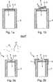
Die Erfindung wird anhand der nachfolgenden Figuren näher erläutert. Es zeigt:The invention will be explained in more detail with reference to the following figures. It shows:
Die Messmembran
Die Schichtstruktur
Hinzu kommt, dass übliche Begleitsubstanzen der Reinigungsmedien, wie Alkohole oder oxidierende Medien wie Hypochlorite, die Alterung der Messmembran
Das Substratmaterial
In einer Ausgestaltung umfasst das Sensorelement
In
In der Untermatrix
In
Die Messmembran
Erfindungsgemäß ist im gezeigten Fall das Sensorelement
Die Messmembran
BezugszeichenlisteLIST OF REFERENCE NUMBERS
- 11
- Sensorkappe sensor cap
- 22
- Substratschicht substrate layer
- 33
- Sensorelement sensor element
- 44
- Funktionsschicht functional layer
- 55
- Sensordeckel sensor cover
- 66
- Gehäuse casing
- 77
- Ausnehmung recess
- 88th
- Messmembran measuring membrane
- 99
- Matrix matrix
- 1010
- Randbereich border area
- 1111
- Medium medium
- 1212
- Analyt analyte
- 1313
- Schichtstruktur layer structure
- 1414
- Stützgitter support grid
- 1515
- Öffnung opening
- 1616
- Endbereich end
- 1717
- Haltegitter holding grid
- 1818
- sensorspezifische Substanz sensor-specific substance
- 1919
- Dichtung / Dichtring Seal / sealing ring
- 2020
- Dichtung / Dichtring Seal / sealing ring
- 2121
- Sensorkomponenten sensor components
- 2222
- Zwischenmatrix intermediate matrix
- 2323
- Untermatrix under matrix
ZITATE ENTHALTEN IN DER BESCHREIBUNG QUOTES INCLUDE IN THE DESCRIPTION
Diese Liste der vom Anmelder aufgeführten Dokumente wurde automatisiert erzeugt und ist ausschließlich zur besseren Information des Lesers aufgenommen. Die Liste ist nicht Bestandteil der deutschen Patent- bzw. Gebrauchsmusteranmeldung. Das DPMA übernimmt keinerlei Haftung für etwaige Fehler oder Auslassungen.This list of the documents listed by the applicant has been generated automatically and is included solely for the better information of the reader. The list is not part of the German patent or utility model application. The DPMA assumes no liability for any errors or omissions.
Zitierte PatentliteraturCited patent literature
- WO 2005/100957 A1[0003]WO 2005/100957 A1[0003]
- US 2003/0068827 A1[0004]US 2003/0068827 A1[0004]
- US 5057277[0005]US 5057277[0005]
- DE 10051220 A1[0006]DE 10051220 A1[0006]
Claims (21)
Translated fromGermanPriority Applications (1)
| Application Number | Priority Date | Filing Date | Title |
|---|---|---|---|
| DE102014112972.5ADE102014112972A1 (en) | 2013-09-12 | 2014-09-09 | Measuring diaphragm for an optochemical or amperometric sensor |
Applications Claiming Priority (3)
| Application Number | Priority Date | Filing Date | Title |
|---|---|---|---|
| DE102013110040 | 2013-09-12 | ||
| DE102013110040.6 | 2013-09-12 | ||
| DE102014112972.5ADE102014112972A1 (en) | 2013-09-12 | 2014-09-09 | Measuring diaphragm for an optochemical or amperometric sensor |
Publications (1)
| Publication Number | Publication Date |
|---|---|
| DE102014112972A1true DE102014112972A1 (en) | 2015-03-12 |
Family
ID=52478712
Family Applications (1)
| Application Number | Title | Priority Date | Filing Date |
|---|---|---|---|
| DE102014112972.5APendingDE102014112972A1 (en) | 2013-09-12 | 2014-09-09 | Measuring diaphragm for an optochemical or amperometric sensor |
Country Status (3)
| Country | Link |
|---|---|
| US (1) | US20150068898A1 (en) |
| CN (1) | CN104458678B (en) |
| DE (1) | DE102014112972A1 (en) |
Cited By (21)
| Publication number | Priority date | Publication date | Assignee | Title |
|---|---|---|---|---|
| DE102015122463A1 (en) | 2015-12-21 | 2017-06-22 | Endress+Hauser Conducta Gmbh+Co. Kg | Membrane and method of making a membrane |
| WO2017137798A1 (en) | 2016-02-08 | 2017-08-17 | Presens Precision Sensing Gmbh | Optical sensor device |
| DE102016110696A1 (en) | 2016-06-10 | 2017-12-14 | Endress+Hauser Conducta Gmbh+Co. Kg | Method for producing a sensor cap with a membrane |
| DE102016123586A1 (en) | 2016-12-06 | 2018-06-07 | Endress+Hauser Conducta Gmbh+Co. Kg | Sensor membrane for an optical and / or amperometric and / or potentiometric sensor and amperometric or optical or potentiometric sensor |
| DE102017114535A1 (en)* | 2017-06-29 | 2019-01-03 | Endress+Hauser Conducta Gmbh+Co. Kg | Sensor membrane, sensor cap and optical sensor |
| DE102017114537A1 (en)* | 2017-06-29 | 2019-01-03 | Endress+Hauser Conducta Gmbh+Co. Kg | Sensor membrane, sensor cap and optical sensor |
| DE102017115420A1 (en) | 2017-07-10 | 2019-01-10 | Endress+Hauser Conducta Gmbh+Co. Kg | sensor |
| DE102017118504A1 (en)* | 2017-08-14 | 2019-02-14 | Endress+Hauser Conducta Gmbh+Co. Kg | Protection device for an optochemical sensor and corresponding optochemical sensor |
| DE102017128564A1 (en) | 2017-12-01 | 2019-06-06 | Endress+Hauser Conducta Gmbh+Co. Kg | Sensor membrane, sensor cap, optical sensor and method for producing a sensor membrane |
| DE102017223851A1 (en)* | 2017-12-28 | 2019-07-04 | Biochip Systems GmbH | Sensor arrangement for detecting at least one material property of a sample and microtiter plate with a plurality of sensor arrangements |
| DE102018204744A1 (en)* | 2018-03-28 | 2019-10-02 | Robert Bosch Gmbh | Chemical analysis device for measuring the ion concentration of an electrolyte and method for its operation |
| US10495619B2 (en) | 2016-08-11 | 2019-12-03 | Pyro Science Gmbh | Device for determining a concentration of an analyte in a gaseous medium |
| DE102018116345A1 (en) | 2018-07-05 | 2020-01-09 | Endress+Hauser Conducta Gmbh+Co. Kg | Sensor membrane, sensor cap and method for applying a sensor membrane |
| DE102018129969A1 (en) | 2018-11-27 | 2020-05-28 | Endress+Hauser Conducta Gmbh+Co. Kg | Sensor membrane, membrane cap and optochemical sensor |
| DE102018129968A1 (en)* | 2018-11-27 | 2020-05-28 | Endress+Hauser Conducta Gmbh+Co. Kg | Electrochemical sensor |
| DE102019113951A1 (en)* | 2019-05-24 | 2020-11-26 | Sentronic GmbH - Gesellschaft für optische Meßsysteme | Functional layer carrier and sensor system comprising such a functional layer carrier |
| DE102020111802A1 (en) | 2020-04-30 | 2021-11-04 | Endress+Hauser Conducta Gmbh+Co. Kg | Calibration device, flexible bag with components of a calibration device and method for calibrating a sensor |
| DE102020134517A1 (en) | 2020-12-21 | 2022-06-23 | Endress+Hauser Conducta Gmbh+Co. Kg | Optical sensor element, optical pH sensor and method for monitoring the function of an optical pH sensor |
| WO2022204746A1 (en) | 2021-04-01 | 2022-10-06 | Oxygen Scientific GmbH | Optical gas sensor having a barrier layer |
| DE102023112004A1 (en)* | 2023-05-08 | 2024-11-14 | Endress+Hauser Conducta Gmbh+Co. Kg | Method for producing a sensor membrane, sensor membrane and a sensor comprising the sensor membrane |
| DE102023133695A1 (en)* | 2023-12-01 | 2025-06-05 | Endress+Hauser Conducta Gmbh+Co. Kg | Sensor spot, sensor cap and sensor with improved light output of the excitation light |
Families Citing this family (5)
| Publication number | Priority date | Publication date | Assignee | Title |
|---|---|---|---|---|
| DE102016103750B4 (en)* | 2015-12-23 | 2018-04-05 | Endress+Hauser Conducta Gmbh+Co. Kg | Sensor cap for an optochemical sensor and corresponding optochemical sensor |
| EP3401668A1 (en)* | 2017-05-12 | 2018-11-14 | Mettler-Toledo GmbH | Optochemical sensor |
| CN109717876B (en)* | 2017-10-31 | 2023-12-26 | 心脏起搏器股份公司 | Structural diffusion membrane for chemical sensors |
| DE102019127914A1 (en)* | 2018-10-19 | 2020-04-23 | Endress+Hauser Conducta Gmbh+Co. Kg | An optochemical sensor unit and a method for the qualitative and / or quantitative determination of an analyte in a measuring medium with the sensor unit |
| DE102020115791A1 (en)* | 2020-06-16 | 2021-12-16 | Presens Precision Sensing Gmbh | SENSOR UNIT, MEASURING METHOD AND MANUFACTURING METHOD |
Citations (4)
| Publication number | Priority date | Publication date | Assignee | Title |
|---|---|---|---|---|
| US5057277A (en) | 1988-10-17 | 1991-10-15 | Hewlett-Packard Company | Chemically sensitive, dimensionally-stable organosilicon material composition |
| DE10051220A1 (en) | 2000-10-16 | 2002-04-25 | Mettler Toledo Gmbh | Optical sensor for determining an analyte and method for its production |
| US20030068827A1 (en) | 2001-10-05 | 2003-04-10 | Ocean Optics, Inc. | Enhanced scattering membranes for improved sensitivity and signal-to-noise of optical chemical sensors, fiber optic oxygen sensor for real time respiration monitoring utilizing same, and method of using sensor |
| WO2005100957A1 (en) | 2004-04-16 | 2005-10-27 | Endress + Hauser Conducta Gesellschaft für Mess- und Regeltechnik mbH | Luminescence sensor for determining and/or monitoring an analyte that is contained in a fluidic process medium |
Family Cites Families (14)
| Publication number | Priority date | Publication date | Assignee | Title |
|---|---|---|---|---|
| US4678904A (en)* | 1984-07-06 | 1987-07-07 | Technology Dynamics, Inc. | Optical measuring device using a spectral modulation sensor having an optically resonant structure |
| FR2695481B1 (en)* | 1992-09-07 | 1994-12-02 | Cylergie Gie | Amperometric measurement device comprising an electrochemical sensor. |
| DE4425135C2 (en)* | 1994-07-15 | 1996-05-02 | Draegerwerk Ag | Amperometric sensor |
| US6080294A (en)* | 1998-07-15 | 2000-06-27 | Atwood Industries, Inc. | Gas sensor with dual electrolytes |
| AU2003253590A1 (en)* | 2002-03-29 | 2003-11-10 | Board Of Regents For The Oklahoma Agricultural And Mechanical Colleges, Acting For And On Behalf Of Oklahoma State University | Implantable biosensor from stratified nanostructured membranes |
| US8425858B2 (en)* | 2005-10-14 | 2013-04-23 | Morpho Detection, Inc. | Detection apparatus and associated method |
| US8293340B2 (en)* | 2005-12-21 | 2012-10-23 | 3M Innovative Properties Company | Plasma deposited microporous analyte detection layer |
| WO2007100588A1 (en)* | 2006-02-27 | 2007-09-07 | Edwards Lifesciences Corporation | Hydrogel for an intravenous amperometric biosensor |
| DE102006025470B4 (en)* | 2006-05-30 | 2018-08-02 | Airbus Defence and Space GmbH | Fluorescence sensor for the detection of gas compositions |
| WO2008136812A2 (en)* | 2007-05-07 | 2008-11-13 | The Board Of Trustees Of The University Of Illinois | Fluorescence detection enhancement using photonic crystal extraction |
| JP4996527B2 (en)* | 2008-04-14 | 2012-08-08 | 日本特殊陶業株式会社 | Laminated gas sensor element and gas sensor |
| US20110017594A1 (en)* | 2009-06-30 | 2011-01-27 | Edwards Lifesciences Corporation | Analyte sensor fabrication |
| CN102590297B (en)* | 2012-03-12 | 2013-11-13 | 浙江大学 | ZnO/enzyme biosensor and preparation method |
| AT512498B1 (en)* | 2012-06-06 | 2013-09-15 | Joanneum Res Forschungsgmbh | Opto-chemical sensor |
- 2014
- 2014-09-09DEDE102014112972.5Apatent/DE102014112972A1/enactivePending
- 2014-09-10USUS14/482,188patent/US20150068898A1/ennot_activeAbandoned
- 2014-09-12CNCN201410466339.0Apatent/CN104458678B/enactiveActive
Patent Citations (4)
| Publication number | Priority date | Publication date | Assignee | Title |
|---|---|---|---|---|
| US5057277A (en) | 1988-10-17 | 1991-10-15 | Hewlett-Packard Company | Chemically sensitive, dimensionally-stable organosilicon material composition |
| DE10051220A1 (en) | 2000-10-16 | 2002-04-25 | Mettler Toledo Gmbh | Optical sensor for determining an analyte and method for its production |
| US20030068827A1 (en) | 2001-10-05 | 2003-04-10 | Ocean Optics, Inc. | Enhanced scattering membranes for improved sensitivity and signal-to-noise of optical chemical sensors, fiber optic oxygen sensor for real time respiration monitoring utilizing same, and method of using sensor |
| WO2005100957A1 (en) | 2004-04-16 | 2005-10-27 | Endress + Hauser Conducta Gesellschaft für Mess- und Regeltechnik mbH | Luminescence sensor for determining and/or monitoring an analyte that is contained in a fluidic process medium |
Cited By (26)
| Publication number | Priority date | Publication date | Assignee | Title |
|---|---|---|---|---|
| DE102015122463A1 (en) | 2015-12-21 | 2017-06-22 | Endress+Hauser Conducta Gmbh+Co. Kg | Membrane and method of making a membrane |
| WO2017137798A1 (en) | 2016-02-08 | 2017-08-17 | Presens Precision Sensing Gmbh | Optical sensor device |
| DE102016110696A1 (en) | 2016-06-10 | 2017-12-14 | Endress+Hauser Conducta Gmbh+Co. Kg | Method for producing a sensor cap with a membrane |
| US20170356839A1 (en)* | 2016-06-10 | 2017-12-14 | Endress+Hauser Conducta Gmbh+Co. Kg | Method for producing a sensor cap with a membrane |
| DE102016110696B4 (en) | 2016-06-10 | 2025-03-20 | Endress+Hauser Conducta Gmbh+Co. Kg | Method for producing a sensor cap with a membrane |
| US10830690B2 (en)* | 2016-06-10 | 2020-11-10 | Endress+Hauser Conducta Gmbh+Co. Kg | Method for producing a sensor cap with a membrane |
| US10495619B2 (en) | 2016-08-11 | 2019-12-03 | Pyro Science Gmbh | Device for determining a concentration of an analyte in a gaseous medium |
| DE102016123586A1 (en) | 2016-12-06 | 2018-06-07 | Endress+Hauser Conducta Gmbh+Co. Kg | Sensor membrane for an optical and / or amperometric and / or potentiometric sensor and amperometric or optical or potentiometric sensor |
| DE102017114537A1 (en)* | 2017-06-29 | 2019-01-03 | Endress+Hauser Conducta Gmbh+Co. Kg | Sensor membrane, sensor cap and optical sensor |
| DE102017114535A1 (en)* | 2017-06-29 | 2019-01-03 | Endress+Hauser Conducta Gmbh+Co. Kg | Sensor membrane, sensor cap and optical sensor |
| DE102017115420A1 (en) | 2017-07-10 | 2019-01-10 | Endress+Hauser Conducta Gmbh+Co. Kg | sensor |
| DE102017118504A1 (en)* | 2017-08-14 | 2019-02-14 | Endress+Hauser Conducta Gmbh+Co. Kg | Protection device for an optochemical sensor and corresponding optochemical sensor |
| DE102017128564A1 (en) | 2017-12-01 | 2019-06-06 | Endress+Hauser Conducta Gmbh+Co. Kg | Sensor membrane, sensor cap, optical sensor and method for producing a sensor membrane |
| DE102017223851B4 (en)* | 2017-12-28 | 2020-08-06 | Biochip Systems GmbH | Sensor arrangement for the detection of at least one material property of a sample and microtiter plate with a plurality of sensor arrangements |
| DE102017223851A1 (en)* | 2017-12-28 | 2019-07-04 | Biochip Systems GmbH | Sensor arrangement for detecting at least one material property of a sample and microtiter plate with a plurality of sensor arrangements |
| DE102018204744A1 (en)* | 2018-03-28 | 2019-10-02 | Robert Bosch Gmbh | Chemical analysis device for measuring the ion concentration of an electrolyte and method for its operation |
| DE102018116345A1 (en) | 2018-07-05 | 2020-01-09 | Endress+Hauser Conducta Gmbh+Co. Kg | Sensor membrane, sensor cap and method for applying a sensor membrane |
| DE102018129968A1 (en)* | 2018-11-27 | 2020-05-28 | Endress+Hauser Conducta Gmbh+Co. Kg | Electrochemical sensor |
| CN111220580A (en)* | 2018-11-27 | 2020-06-02 | 恩德莱斯和豪瑟尔分析仪表两合公司 | Sensor membrane, membrane cover and photochemical sensor |
| DE102018129969A1 (en) | 2018-11-27 | 2020-05-28 | Endress+Hauser Conducta Gmbh+Co. Kg | Sensor membrane, membrane cap and optochemical sensor |
| DE102019113951A1 (en)* | 2019-05-24 | 2020-11-26 | Sentronic GmbH - Gesellschaft für optische Meßsysteme | Functional layer carrier and sensor system comprising such a functional layer carrier |
| DE102020111802A1 (en) | 2020-04-30 | 2021-11-04 | Endress+Hauser Conducta Gmbh+Co. Kg | Calibration device, flexible bag with components of a calibration device and method for calibrating a sensor |
| DE102020134517A1 (en) | 2020-12-21 | 2022-06-23 | Endress+Hauser Conducta Gmbh+Co. Kg | Optical sensor element, optical pH sensor and method for monitoring the function of an optical pH sensor |
| WO2022204746A1 (en) | 2021-04-01 | 2022-10-06 | Oxygen Scientific GmbH | Optical gas sensor having a barrier layer |
| DE102023112004A1 (en)* | 2023-05-08 | 2024-11-14 | Endress+Hauser Conducta Gmbh+Co. Kg | Method for producing a sensor membrane, sensor membrane and a sensor comprising the sensor membrane |
| DE102023133695A1 (en)* | 2023-12-01 | 2025-06-05 | Endress+Hauser Conducta Gmbh+Co. Kg | Sensor spot, sensor cap and sensor with improved light output of the excitation light |
Also Published As
| Publication number | Publication date |
|---|---|
| US20150068898A1 (en) | 2015-03-12 |
| CN104458678B (en) | 2018-09-18 |
| CN104458678A (en) | 2015-03-25 |
Similar Documents
| Publication | Publication Date | Title |
|---|---|---|
| DE102014112972A1 (en) | Measuring diaphragm for an optochemical or amperometric sensor | |
| DE102016103750B4 (en) | Sensor cap for an optochemical sensor and corresponding optochemical sensor | |
| EP2926128B1 (en) | Chemically-stable sensor | |
| DE102017115420A1 (en) | sensor | |
| EP0478720B1 (en) | Measurement probe for the amperometric determination of gases and/or non-ionic compounds in a measurement medium | |
| AT512498B1 (en) | Opto-chemical sensor | |
| DE102004033303A1 (en) | Device for determining and / or monitoring an analyte contained in a fluid process medium | |
| DE2009937A1 (en) | Electrochemical cell for determining the ammonia content | |
| DE19781639B4 (en) | Electrochemical sensor with a non-aqueous electrolyte system | |
| EP3030886B1 (en) | Optical sensor and arrangement for quantitatively detecting an analyte | |
| DE2006682A1 (en) | Polarography probe | |
| EP2363704A1 (en) | Calibratable sensor element for reaction container | |
| DE102016123700A1 (en) | Sensor for determining a measured variable dependent on a concentration of reactive oxygen species | |
| DE102020109901A1 (en) | Optochemical sensor and method for measured value correction | |
| DE102009056417A1 (en) | Sensor protection device | |
| DE102017118504A1 (en) | Protection device for an optochemical sensor and corresponding optochemical sensor | |
| DE102016110696A1 (en) | Method for producing a sensor cap with a membrane | |
| DE102014107837A1 (en) | Optical sensor for the quantitative detection of an analyte in a sample and method for producing the sensor | |
| DE102018129968A1 (en) | Electrochemical sensor | |
| DE102013007872B4 (en) | Electrochemical gas sensor, process for its production and its use | |
| DE102009047299A1 (en) | Ozone sensor for detection of ozone in water during e.g. drinking water processing, has liquid-impermeable element arranged with respect to sensing element for avoiding direct contact between liquid and detecting portion of sensing element | |
| DE10053979B4 (en) | Electrochemical electrode | |
| AT390145B (en) | METHOD FOR DETERMINING THE CONCENTRATION OF SUBSTANCES, IN PARTICULAR OXYGEN | |
| CH679806A5 (en) | ||
| DE2930074C2 (en) | Measuring device for determining the partial pressure of oxygen in liquids and gases |
Legal Events
| Date | Code | Title | Description |
|---|---|---|---|
| R081 | Change of applicant/patentee | Owner name:ENDRESS+HAUSER CONDUCTA GMBH+CO. KG, DE Free format text:FORMER OWNER: ENDRESS + HAUSER CONDUCTA GESELLSCHAFT FUER MESS- UND REGELTECHNIK MBH + CO. KG, 70839 GERLINGEN, DE | |
| R082 | Change of representative | Representative=s name:KOSLOWSKI, CHRISTINE, DIPL.-CHEM. DR. RER. NAT, DE | |
| R012 | Request for examination validly filed | ||
| R082 | Change of representative | Representative=s name:KRATT-STUBENRAUCH, KAI, DR., DE | |
| R082 | Change of representative | Representative=s name:KRATT-STUBENRAUCH, KAI, DR., DE | |
| R016 | Response to examination communication |