DE102014112043A1 - Tensioned opening device for monomer containers - Google Patents
Tensioned opening device for monomer containersDownload PDFInfo
- Publication number
- DE102014112043A1 DE102014112043A1DE102014112043.4ADE102014112043ADE102014112043A1DE 102014112043 A1DE102014112043 A1DE 102014112043A1DE 102014112043 ADE102014112043 ADE 102014112043ADE 102014112043 A1DE102014112043 A1DE 102014112043A1
- Authority
- DE
- Germany
- Prior art keywords
- opening device
- monomer liquid
- ampoule
- liquid container
- spring
- Prior art date
- Legal status (The legal status is an assumption and is not a legal conclusion. Google has not performed a legal analysis and makes no representation as to the accuracy of the status listed.)
- Ceased
Links
- 239000000178monomerSubstances0.000titleclaimsabstractdescription149
- 239000007788liquidSubstances0.000claimsabstractdescription145
- 238000004146energy storageMethods0.000claimsabstractdescription49
- 238000000034methodMethods0.000claimsabstractdescription14
- 239000003708ampulSubstances0.000claimsdescription129
- 239000011888foilSubstances0.000claimsdescription40
- 239000004568cementSubstances0.000claimsdescription33
- 239000011521glassSubstances0.000claimsdescription25
- 239000000843powderSubstances0.000claimsdescription25
- 208000002193PainDiseases0.000claimsdescription6
- 229910000831SteelInorganic materials0.000claimsdescription6
- 239000010959steelSubstances0.000claimsdescription6
- 239000002184metalSubstances0.000claimsdescription5
- 239000012634fragmentSubstances0.000claimsdescription4
- 229920003229poly(methyl methacrylate)Polymers0.000description15
- 239000004926polymethyl methacrylateSubstances0.000description15
- 239000002639bone cementSubstances0.000description14
- 210000003746featherAnatomy0.000description7
- 229920003023plasticPolymers0.000description7
- 239000004033plasticSubstances0.000description7
- VVQNEPGJFQJSBK-UHFFFAOYSA-NMethyl methacrylateChemical compoundCOC(=O)C(C)=CVVQNEPGJFQJSBK-UHFFFAOYSA-N0.000description5
- 206010016352Feeling of relaxationDiseases0.000description4
- 230000006835compressionEffects0.000description3
- 238000007906compressionMethods0.000description3
- 238000011161developmentMethods0.000description3
- 229920000642polymerPolymers0.000description3
- OMPJBNCRMGITSC-UHFFFAOYSA-NBenzoylperoxideChemical compoundC=1C=CC=CC=1C(=O)OOC(=O)C1=CC=CC=C1OMPJBNCRMGITSC-UHFFFAOYSA-N0.000description2
- 241001295925GegenesSpecies0.000description2
- BAPJBEWLBFYGME-UHFFFAOYSA-NMethyl acrylateChemical compoundCOC(=O)C=CBAPJBEWLBFYGME-UHFFFAOYSA-N0.000description2
- PPBRXRYQALVLMV-UHFFFAOYSA-NStyreneChemical compoundC=CC1=CC=CC=C1PPBRXRYQALVLMV-UHFFFAOYSA-N0.000description2
- 230000004913activationEffects0.000description2
- 239000012190activatorSubstances0.000description2
- 235000019400benzoyl peroxideNutrition0.000description2
- 239000000463materialSubstances0.000description2
- GYVGXEWAOAAJEU-UHFFFAOYSA-Nn,n,4-trimethylanilineChemical compoundCN(C)C1=CC=C(C)C=C1GYVGXEWAOAAJEU-UHFFFAOYSA-N0.000description2
- 238000006116polymerization reactionMethods0.000description2
- 238000003825pressingMethods0.000description2
- 238000003860storageMethods0.000description2
- BUHVIAUBTBOHAG-FOYDDCNASA-N(2r,3r,4s,5r)-2-[6-[[2-(3,5-dimethoxyphenyl)-2-(2-methylphenyl)ethyl]amino]purin-9-yl]-5-(hydroxymethyl)oxolane-3,4-diolChemical compoundCOC1=CC(OC)=CC(C(CNC=2C=3N=CN(C=3N=CN=2)[C@H]2[C@@H]([C@H](O)[C@@H](CO)O2)O)C=2C(=CC=CC=2)C)=C1BUHVIAUBTBOHAG-FOYDDCNASA-N0.000description1
- 238000010521absorption reactionMethods0.000description1
- 238000013459approachMethods0.000description1
- 230000001687destabilizationEffects0.000description1
- 238000005516engineering processMethods0.000description1
- 239000003999initiatorSubstances0.000description1
- 238000004519manufacturing processMethods0.000description1
- 239000000203mixtureSubstances0.000description1
- NJPPVKZQTLUDBO-UHFFFAOYSA-NnovaluronChemical compoundC1=C(Cl)C(OC(F)(F)C(OC(F)(F)F)F)=CC=C1NC(=O)NC(=O)C1=C(F)C=CC=C1FNJPPVKZQTLUDBO-UHFFFAOYSA-N0.000description1
- 230000008092positive effectEffects0.000description1
- 238000010526radical polymerization reactionMethods0.000description1
- 230000002040relaxant effectEffects0.000description1
- 238000007789sealingMethods0.000description1
- 238000000926separation methodMethods0.000description1
- 230000000087stabilizing effectEffects0.000description1
- 230000001954sterilising effectEffects0.000description1
- 238000004659sterilization and disinfectionMethods0.000description1
- 239000000725suspensionSubstances0.000description1
- 238000010557suspension polymerization reactionMethods0.000description1
- 230000008961swellingEffects0.000description1
- 230000008719thickeningEffects0.000description1
- 238000012546transferMethods0.000description1
- 238000013519translationMethods0.000description1
Images


Classifications
- B—PERFORMING OPERATIONS; TRANSPORTING
- B67—OPENING, CLOSING OR CLEANING BOTTLES, JARS OR SIMILAR CONTAINERS; LIQUID HANDLING
- B67B—APPLYING CLOSURE MEMBERS TO BOTTLES JARS, OR SIMILAR CONTAINERS; OPENING CLOSED CONTAINERS
- B67B7/00—Hand- or power-operated devices for opening closed containers
- B67B7/24—Hole-piercing devices
- A—HUMAN NECESSITIES
- A61—MEDICAL OR VETERINARY SCIENCE; HYGIENE
- A61B—DIAGNOSIS; SURGERY; IDENTIFICATION
- A61B17/00—Surgical instruments, devices or methods
- A61B17/56—Surgical instruments or methods for treatment of bones or joints; Devices specially adapted therefor
- A61B17/58—Surgical instruments or methods for treatment of bones or joints; Devices specially adapted therefor for osteosynthesis, e.g. bone plates, screws or setting implements
- A61B17/88—Osteosynthesis instruments; Methods or means for implanting or extracting internal or external fixation devices
- A61B17/8802—Equipment for handling bone cement or other fluid fillers
- A61B17/8833—Osteosynthesis tools specially adapted for handling bone cement or fluid fillers; Means for supplying bone cement or fluid fillers to introducing tools, e.g. cartridge handling means
- B—PERFORMING OPERATIONS; TRANSPORTING
- B67—OPENING, CLOSING OR CLEANING BOTTLES, JARS OR SIMILAR CONTAINERS; LIQUID HANDLING
- B67B—APPLYING CLOSURE MEMBERS TO BOTTLES JARS, OR SIMILAR CONTAINERS; OPENING CLOSED CONTAINERS
- B67B7/00—Hand- or power-operated devices for opening closed containers
- B67B7/92—Hand- or power-operated devices for opening closed containers by breaking, e.g. for ampoules
- A—HUMAN NECESSITIES
- A61—MEDICAL OR VETERINARY SCIENCE; HYGIENE
- A61B—DIAGNOSIS; SURGERY; IDENTIFICATION
- A61B17/00—Surgical instruments, devices or methods
- A61B17/56—Surgical instruments or methods for treatment of bones or joints; Devices specially adapted therefor
- A61B17/58—Surgical instruments or methods for treatment of bones or joints; Devices specially adapted therefor for osteosynthesis, e.g. bone plates, screws or setting implements
- A61B17/88—Osteosynthesis instruments; Methods or means for implanting or extracting internal or external fixation devices
- A61B17/8802—Equipment for handling bone cement or other fluid fillers
- A61B17/8833—Osteosynthesis tools specially adapted for handling bone cement or fluid fillers; Means for supplying bone cement or fluid fillers to introducing tools, e.g. cartridge handling means
- A61B2017/8838—Osteosynthesis tools specially adapted for handling bone cement or fluid fillers; Means for supplying bone cement or fluid fillers to introducing tools, e.g. cartridge handling means for mixing bone cement or fluid fillers
- B—PERFORMING OPERATIONS; TRANSPORTING
- B01—PHYSICAL OR CHEMICAL PROCESSES OR APPARATUS IN GENERAL
- B01F—MIXING, e.g. DISSOLVING, EMULSIFYING OR DISPERSING
- B01F35/00—Accessories for mixers; Auxiliary operations or auxiliary devices; Parts or details of general application
- B01F35/71—Feed mechanisms
- B01F35/713—Feed mechanisms comprising breaking packages or parts thereof, e.g. piercing or opening sealing elements between compartments or cartridges
- B01F35/7131—Breaking or perforating packages, containers or vials
Landscapes
- Health & Medical Sciences (AREA)
- Engineering & Computer Science (AREA)
- Mechanical Engineering (AREA)
- Life Sciences & Earth Sciences (AREA)
- Orthopedic Medicine & Surgery (AREA)
- Surgery (AREA)
- Heart & Thoracic Surgery (AREA)
- Biomedical Technology (AREA)
- Nuclear Medicine, Radiotherapy & Molecular Imaging (AREA)
- Medical Informatics (AREA)
- Molecular Biology (AREA)
- Animal Behavior & Ethology (AREA)
- General Health & Medical Sciences (AREA)
- Public Health (AREA)
- Veterinary Medicine (AREA)
- Medical Preparation Storing Or Oral Administration Devices (AREA)
- Surgical Instruments (AREA)
- Prostheses (AREA)
- Accessories For Mixers (AREA)
Abstract
Translated fromGerman
Description
Translated fromGermanDie Erfindung betrifft eine Öffnungsvorrichtung zum Öffnen eines Monomerflüssigkeitsbehälters.The invention relates to an opening device for opening a monomer liquid container.
Die Erfindung betrifft ferner ein Vakuummischsystem mit einer solchen Öffnungsvorrichtung und ein Verfahren zum Öffnen eines Monomerflüssigkeitsbehälters.The invention further relates to a vacuum mixing system with such an opening device and a method for opening a monomer liquid container.
Gegenstand der Erfindung ist somit eine Vorrichtung zum Öffnen von Monomerflüssigkeitsbehältern von Pulver-Flüssigkeits-Polymethylmethacrylat-Knochenzementen zur Herstellung derselben. Ein weiterer Gegenstand der Erfindung ist ein geschlossenes Vakuummischsystem für die Lagerung, Vermischung und den Austrag von Polymethylmethacrylat-Knochenzement.The invention thus relates to a device for opening of monomer liquid containers of powder-liquid polymethyl methacrylate bone cements for the production thereof. Another object of the invention is a closed vacuum mixing system for the storage, mixing and discharge of polymethyl methacrylate bone cement.
Polymethylmethacrylat-(PMMA)-Knochenzemente gehen auf die grundlegenden Arbeiten von Sir Charnley zurück. PMMA-Knochenzemente bestehen aus einer flüssigen Monomerkomponente und einer Pulverkomponente. Die Monomerkomponente enthält im Allgemeinen das Monomer Methylmethacrylat und einen darin gelösten Aktivator (N,N-Dimethyl-p-toluidin). Die Pulverkomponente, auch als Knochenzementpulver bezeichnet, weist ein oder mehrere Polymere, einen Röntgenopaker und den Initiator Dibenzoylperoxid auf. Die Polymere der Pulverkomponente werden auf Basis von Methylmethacrylat und Comonomeren, wie Styren, Methylacrylat oder ähnlichen Monomeren durch Polymerisation, vorzugsweise Suspensionspolymerisation, hergestellt. Beim Vermischen der Pulverkomponente mit der Monomerkomponente entsteht durch Quellung der Polymere der Pulverkomponente im Methylmethacrylat ein plastisch verformbarer Teig, der eigentliche Knochenzement. Beim Vermischen der Pulverkomponente mit der Monomerkomponente reagiert der Aktivator N,N-Dimethyl-p-toluidin mit Dibenzoylperoxid unter Bildung von Radikalen. Die gebildeten Radikale initiieren die radikalische Polymerisation des Methylmethacrylats. Mit fortschreitender Polymerisation des Methylmethacrylats erhöht sich die Viskosität des Zementteigs, bis dieser erstarrt.Polymethylmethacrylate (PMMA) bone cements go back to the fundamental work of Sir Charnley. PMMA bone cements consist of a liquid monomer component and a powder component. The monomer component generally contains the monomer methyl methacrylate and an activator (N, N-dimethyl-p-toluidine) dissolved therein. The powder component, also referred to as bone cement powder, has one or more polymers, an X-ray opaque and the initiator dibenzoyl peroxide. The polymers of the powder component are prepared based on methyl methacrylate and comonomers such as styrene, methyl acrylate or similar monomers by polymerization, preferably suspension polymerization. When the powder component is mixed with the monomer component, swelling of the polymers of the powder component in methyl methacrylate produces a plastically deformable dough, the actual bone cement. Upon mixing the powder component with the monomer component, the activator reacts N, N-dimethyl-p-toluidine with dibenzoyl peroxide to form radicals. The radicals formed initiate the radical polymerization of the methyl methacrylate. As the polymerization of methyl methacrylate progresses, the viscosity of the cement dough increases until it solidifies.
PMMA-Knochenzemente können in geeigneten Mischbechern mit Hilfe von Spateln durch Vermischen des Zementpulvers mit der Monomerflüssigkeit vermischt werden.PMMA bone cements can be mixed in suitable mixing beakers by means of spatulas by mixing the cement powder with the monomer liquid.
Nachteilig ist an dieser Vorgehensweise, dass Lufteinschlüsse im gebildeten Zementteig vorhanden sein können, die später eine Destabilisierung des Knochenzements verursachen können. Aus diesem Grund wird das Vermischen von Knochenzementpulver mit der Monomerflüssigkeit in Vakuummischsystemen bevorzugt, weil durch Mischen im Vakuum Lufteinschlüsse aus dem Zementteig weitgehend entfernt werden und damit eine optimale Zementqualität erreicht wird. Im Vakuum gemischte Knochenzemente haben eine deutlich verringerte Porosität und zeigen daher verbesserte mechanische Eigenschaften. Es wurden eine Vielzahl von Vakuum-Zementiersystemen offen gelegt, von denen exemplarisch folgende genannt sind:
Eine Weiterentwicklung in der Zementiertechnik stellen Zementiersysteme dar, in denen sowohl das Zementpulver als auch die Monomerflüssigkeit bereits in separaten Kompartimenten der Mischsysteme verpackt sind und die erst unmittelbar vor der Zementapplikation im Zementiersystem miteinander vermischt werden. Solche Full-Prepacked-Mischsysteme wurden mit der
Das Patent
Bei den bisher üblichen Vakuummischsystemen erfolgt die Öffnung des Monomerflüssigkeitsbehälters entweder durch manuelles Abdrehen des Ampullenkopfs, wie beispielsweise in der
Die Aufgabe der Erfindung besteht also darin, die Nachteile des Stands der Technik zu überwinden. Insbesondere soll eine Öffnungsvorrichtung für einen Monomerflüssigkeitsbehälter, ein Vakuummischsystem und ein Verfahren zum Öffnen eines Monomerflüssigkeitsbehälters bereitgestellt werden, die eine möglichst stark vereinfachte Anwendung ermöglicht. Dabei soll der Monomerflüssigkeitsbehälter innerhalb eines geschlossenen Systems beziehungsweise eines geschlossenen oder verschließbaren Vakuummischsystems zu öffnen sein, ohne dass Teile oder Tröpfchen des Inhalts nach außen abgegeben werden können.The object of the invention is therefore to overcome the disadvantages of the prior art. In particular, an opening device for a monomer liquid container, a vacuum mixing system and a method for opening a monomer liquid container is to be provided, which enables the simplest possible application. It should be the monomer liquid container within a closed system or be open to a closed or lockable vacuum mixing system, without parts or droplets of the contents can be discharged to the outside.
Eine Aufgabe der Erfindung ist dabei ferner darin zu sehen, eine Vorrichtung zur nicht manuellen Öffnung von Monomerflüssigkeitsbehältern zu entwickeln. Das bedeutet, die Vorrichtung soll nach Aktivierung eine sichere selbsttätige Öffnung des Monomerflüssigkeitsbehälters bewirken. Der Antrieb der Vorrichtung darf dabei nicht über externe Energiequellen angetrieben werden. Es soll eine einfache, lagerfähige Energiequelle eingesetzt werden, die in ein geschlossenes Vakuummischsystem integriert werden kann.An object of the invention is further to be seen in developing a device for non-manual opening of monomer liquid containers. This means that the device should cause a safe automatic opening of the monomer liquid container after activation. The drive of the device must not be driven by external energy sources. It is a simple, storable energy source can be used, which can be integrated into a closed vacuum mixing system.
Des Weiteren soll ein geschlossenes Vakuummischsystem entwickelt werden, in der die Öffnungsvorrichtung zur Öffnung des Monomerflüssigkeitsbehälters integriert ist. Das Vakuummischsystem soll eine Zementkartusche enthalten, in der ein Zementpulver gelagert ist, sowie einen davon separaten Monomerflüssigkeitsbehälter, in dem sich die Monomerflüssigkeit befindet. Die Monomerflüssigkeit wird dadurch getrennt von dem Zementpulver gelagert. Vor und während der Vermischung der beiden Zementkomponenten – dem Zementpulver mit der Monomerflüssigkeit – soll ein Kontakt der medizinischen Anwender mit diesen Komponenten ausgeschlossen sein. Die Öffnung des Monomerflüssigkeitsbehälters und der Transfer der Monomerflüssigkeit sollen daher in einem geschlossenen System erfolgen. Das Zementpulver darf ebenfalls nicht in Kontakt zum medizinischen Anwender kommen.Furthermore, a closed vacuum mixing system is to be developed, in which the opening device for the opening of the monomer liquid container is integrated. The vacuum mixing system is intended to include a cement cartridge in which a cement powder is stored and a separate monomer liquid container in which the monomer liquid is located. The monomer liquid is thereby stored separately from the cement powder. Before and during the mixing of the two cement components - the cement powder with the monomer liquid - contact of the medical user with these components should be excluded. The opening of the monomer liquid container and the transfer of the monomer liquid should therefore be carried out in a closed system. The cement powder must also not come into contact with the medical user.
Die Aufgaben der Erfindung werden gelöst durch eine Öffnungsvorrichtung zum Öffnen eines Monomerflüssigkeitsbehälters aufweisend:
- a) eine Positionierhilfe zur Positionierung des Monomerflüssigkeitsbehälters,
- b) eine Öffnungseinrichtung zum Öffnen des Monomerflüssigkeitsbehälters, wobei die Öffnungseinrichtung gegen die Positionierhilfe beweglich gelagert ist und/oder die Positionierhilfe gegen die Öffnungseinrichtung beweglich gelagert ist, und
- c) zumindest ein elastisch deformierbares Energiespeicherelement zur Speicherung elastischer Energie, wobei eine Bewegung der Öffnungseinrichtung und/oder eine Bewegung der Positionierhilfe mit der elastischen Energie des zumindest einen elastisch deformierbaren Energiespeicherelements anzutreiben ist und der Monomerflüssigkeitsbehälter durch die Bewegung der Positionierhilfe mit dem Monomerflüssigkeitsbehälter und der Öffnungseinrichtung relativ zueinander zu öffnen ist.
- a) a positioning aid for positioning the monomer liquid container,
- b) an opening device for opening the monomer liquid container, wherein the opening device is movably mounted against the positioning aid and / or the positioning aid is movably mounted against the opening device, and
- c) at least one elastically deformable energy storage element for storing elastic energy, wherein movement of the opening device and / or movement of the positioning aid with the elastic energy of the at least one elastically deformable energy storage element is to be driven and the monomer liquid container by the movement of the positioning aid with the monomer liquid container and the opening device is to open relative to each other.
Der Monomerflüssigkeitsbehälter kann Teil der Öffnungsvorrichtung sein, es kann aber auch vorgesehen sein, dass der Monomerflüssigkeitsbehälter in die Öffnungsvorrichtung eingesetzt werden muss, um ihn mit der Öffnungsvorrichtung zu öffnen. In dem Monomerflüssigkeitsbehälter ist bevorzugt eine Monomerflüssigkeit enthalten. Die Positionierhilfe dient lediglich dazu, den Monomerflüssigkeitsbehälter derart in einer Position zu halten oder zu drücken, dass er mit der Öffnungseinrichtung geöffnet werden kann, ohne dass sich der Monomerflüssigkeitsbehälter aufgrund der durch die Öffnungseinrichtung bewirkte Kraft derart deformiert oder bewegt, dass er nicht geöffnet wird. Die elastische Energie kann einfach zur unmittelbaren Bewegung der Öffnungseinrichtung und/oder des Monomerflüssigkeitsbehälters eingesetzt werden. Es ist auch möglich eine Übersetzung oder ein Gestänge oder ähnliches vorzusehen, um die elastische Kraft auf die Öffnungseinrichtung und/oder die Positionierhilfe zu vermitteln.The monomer liquid container may be part of the opening device, but it may also be provided that the monomer liquid container must be inserted into the opening device in order to open it with the opening device. In the monomer liquid container, a monomer liquid is preferably contained. The positioning aid serves merely to hold or press the monomer liquid container in a position such that it can be opened with the opening device without the monomer liquid container being deformed or moved in such a way that it is not opened due to the force caused by the opening device. The elastic energy can be easily used for the immediate movement of the opening device and / or the monomer liquid container. It is also possible to provide a translation or a linkage or the like to impart the elastic force to the opening device and / or the positioning aid.
Bevorzugt wird die Öffnungseinrichtung gegen den Monomerflüssigkeitsbehälter gedrückt und öffnet diesen, wenn die Kraft, die durch das elastische Energiespeicherelement vermittelt wird, über die Öffnungseinrichtung auf den Monomerflüssigkeitsbehälter groß genug ist, um diesen aufzubrechen, zu zerbrechen, aufzuschneiden, zu perforieren, zu durchstoßen oder allgemein zu öffnen. Theoretisch kann der Monomerflüssigkeitsbehälter auch durch aufreißen geöffnet werden, indem die Öffnungseinrichtung an dem Behälter befestigt ist und durch den Zug von dem Monomerflüssigkeitsbehälter weg diesen öffnet. Dies kann beispielsweise mit Hilfe von Zugfedern geschehen, die an dem Monomerflüssigkeitsbehälter befestigt sind, so dass sie diesen aufreißen können.Preferably, the opening means is pushed against the monomer liquid container and opens it when the force imparted by the elastic energy storage element through the opening means on the monomer liquid container is large enough to rupture, break, cut, perforate, puncture or generally to open. Theoretically, the monomer liquid container may also be opened by tearing open by attaching the opening means to the container and opening it by pulling it away from the monomer liquid container. This can be done, for example, by means of tension springs, which are attached to the monomer liquid container so that they can tear it.
Bei erfindungsgemäßen Öffnungsvorrichtungen kann vorgesehen sein, dass die Öffnungsvorrichtung ein Gefäß zur Aufnahme des Monomerflüssigkeitsbehälters aufweist, insbesondere ein geschlossenes oder verschließbares Gefäß zur Aufnahme des Monomerflüssigkeitsbehälters aufweist, wobei bevorzugt die Positionierhilfe im Inneren des Gefäßes angeordnet ist, besonders bevorzugt an einer Innenwandung des Gefäßes angeordnet ist.In opening devices according to the invention it can be provided that the opening device has a vessel for receiving the monomer liquid container, in particular a closed or closable vessel for receiving the monomer liquid container, wherein preferably the positioning aid is arranged in the interior of the vessel, is particularly preferably arranged on an inner wall of the vessel ,
Mit einem solchen Gefäß kann sichergestellt werden, dass keine Monomerflüssigkeit aus dem geöffneten Monomerflüssigkeitsbehälter ungewollt in die Umgebung gelangen kann. Die Öffnungsvorrichtung und/oder das Energiespeicherelement können sich dabei auch außerhalb des Gefäßes und auch des geschlossenen oder verschließbaren Gefäßes befinden. Hierzu weist das Gefäß bevorzugt eine deformierbare Wandung auf, über die eine Kraft ins Innere des Gefäßes auf den Monomerflüssigkeitsbehälter weitergeleitet werden kann.With such a vessel it can be ensured that no monomer liquid from the opened monomer liquid container can unintentionally enter the environment. The opening device and / or the energy storage element can also be located outside of the vessel and also of the closed or closable vessel. For this purpose, the vessel preferably has a deformable wall, via which a force can be passed on to the interior of the vessel to the monomer liquid container.
Ferner kann vorgesehen sein, dass der Monomerflüssigkeitsbehälter eine Ampulle ist, insbesondere eine Glasampulle ist, die mit der Positionierhilfe zu positionieren oder positioniert ist, insbesondere zu halten oder gehalten ist, wobei bevorzugt die Öffnungseinrichtung eine Brecheinrichtung ist, die zum Öffnen der Ampulle die Ampulle zerbricht oder aufbricht, besonders bevorzugt einen Ampullenkopf der Ampulle abbricht oder aufbricht.Furthermore, it can be provided that the monomer liquid container is an ampoule, in particular a glass ampoule which is to be positioned or positioned with the positioning aid, in particular to be held or held, wherein preferably the opening device is a crushing device which breaks or breaks open the ampoule for opening the ampoule, particularly preferably breaks off or breaks open an ampoule head of the ampoule ,
Um das Aufbrechen oder Zerbrechen der Ampulle zu erleichtern, kann an der Ampulle wenigstens eine Sollbruchstelle vorgesehen sein. Die Brecheinrichtung kann als Stößel mit einem stumpfen Ende oder mit einer Kante ausgeführt sein. In solchen Ampullen kann die Monomerflüssigkeit besonders lange und dauerhaft gelagert werden.In order to facilitate the breaking up or breaking of the ampoule, at least one predetermined breaking point can be provided on the ampoule. The crushing device may be designed as a ram with a blunt end or with an edge. In such ampoules, the monomer liquid can be stored for a particularly long and durable.
Des Weiteren kann auch vorgesehen sein, dass am Gefäß ein Ampullenhalter angeordnet ist, mit dem die Ampulle fixiert ist oder fixierbar ist.Furthermore, it can also be provided that an ampoule holder is arranged on the vessel, with which the ampoule is fixed or can be fixed.
Hierdurch kann der Aufbau kompakt gestaltet werden und die Stabilität des Gefäßes kann zur Halterung und Stabilisierung des Ampullenhalters eingesetzt werden.As a result, the structure can be made compact and the stability of the vessel can be used for holding and stabilizing the ampoule holder.
Auch kann vorgesehen sein, dass das Gefäß einen Raum für die Aufnahme eines Ampullenkopfs der Ampulle aufweist, wobei dieser Raum mindestens eine mechanisch deformierbare Wand besitzt, an welcher der Ampullenkopf anliegt oder sich in nahem Abstand dazu befindet, wobei die durch die elastische Energie angetriebene Öffnungseinrichtung die mechanisch deformierbare Wand derart deformiert, dass der Ampullenkopf abbricht oder aufbricht, wobei bevorzugt mindestens ein für Flüssigkeiten durchlässiges Siebelement oder Filterelement vorgesehen ist, das im Raum zur Zurückhaltung des Ampullenkopfs und/oder von Bruchstücken der Ampulle unterhalb des Ampullenkopfs angeordnet ist.It can also be provided that the vessel has a space for receiving an ampoule head of the ampoule, this space has at least one mechanically deformable wall on which the ampoule head rests or is in close proximity thereto, wherein the driven by the elastic energy opening means deforming the mechanically deformable wall such that the ampoule head breaks off or breaks open, wherein preferably at least one liquid-permeable sieve element or filter element is provided, which is arranged in the space for retaining the ampoule head and / or fragments of the ampoule below the ampoule head.
Der Ampullenkopf befindet sich im nahen Abstand zu der elastische deformierbaren Wand, wenn die Auslenkung der deformierbaren Wand, die durch die Öffnungseinrichtung bewirkt wird, ausreicht, um den Ampullenkopf abzubrechen oder aufzubrechen. Bevorzugt ist die der Ampullenkopf nicht mehr als 25 mm von der elastischen Wand beabstandet, besonders bevorzugt nicht mehr als 10 mm von der elastischen Wand beabstandet, ganz besonders bevorzugt nicht mehr als 5 mm von der elastischen Wand beabstandet. Hierdurch wird ein vollkommen geschlossenes System bereitgestellt, bei dem die Monomerflüssigkeit nur mit dem Inneren des Gefäßes in Kontakt kommt und ein Austreten von Monomerflüssigkeit zuverlässig vermieden werden kann. Durch das Auffangen abgebrochener Bruchstücke der Ampulle werden störende Splitter ferngehalten. Hierdurch kann auch eine Glasampulle gefahrlos als Monomerflüssigkeitsbehälter eingesetzt werden.The ampoule head is in close proximity to the resilient deformable wall when the deflection of the deformable wall caused by the opening means is sufficient to break or rupture the ampoule head. Preferably, the ampoule head is spaced no more than 25 mm from the elastic wall, more preferably not more than 10 mm apart from the elastic wall, most preferably not more than 5 mm apart from the elastic wall. As a result, a completely closed system is provided in which the monomer liquid comes into contact only with the interior of the vessel and leakage of monomer liquid can be reliably prevented. By collecting broken fragments of the ampoule disturbing splinters are kept away. As a result, a glass ampoule can be safely used as a monomer liquid container.
Mit einer Weiterbildung der vorliegenden Erfindung wird vorgeschlagen, dass die Öffnungseinrichtung ein linear beweglich gelagerter Stößel ist und die lineare Bewegung des Stößels mit der elastischen Energie des zumindest einen elastisch deformierbaren Energiespeicherelements anzutreiben ist.With a development of the present invention it is proposed that the opening device is a linearly movably mounted plunger and the linear movement of the plunger is to be driven with the elastic energy of the at least one elastically deformable energy storage element.
Mit dem Stößel lässt sich ein aufbrechbarer Monomerflüssigkeitsbehälter einfach öffnen. Der Stößel lässt sich besonders gut mit einer Feder als elastisches Energiespeicherelement antreiben.With the plunger, a breakable monomer liquid container can be opened easily. The plunger can be driven particularly well with a spring as an elastic energy storage element.
Gemäß einer alternativen erfindungsgemäßen Ausführungsform kann vorgesehen sein, dass der Monomerflüssigkeitsbehälter ein Folienbeutel ist, der mit der Positionierhilfe zu positionieren oder positioniert ist, insbesondere zu halten oder gehalten ist, wobei bevorzugt die Öffnungseinrichtung eine Klinge oder ein Stechdorn ist, insbesondere ein hohler Stechdorn ist, der zum Öffnen des Folienbeutels den Folienbeutel aufschneidet oder aufsticht.According to an alternative embodiment of the invention, it can be provided that the monomer liquid container is a foil bag which is to be positioned or positioned, in particular held or held, with the positioning aid, wherein the opening device is preferably a blade or a piercing spike, in particular a hollow spike, the opening of the film bag, the foil bag cuts or pierces.
Bei dieser Variante wird ein Folienbeutel, in dem die Monomerflüssigkeit enthalten ist, durch aufschlitzen oder aufstechen geöffnet. Dies hat den Vorteil, dass die Beutel sehr leicht und mit wenig Energieaufwand sehr zuverlässig zu öffnen sind. Auch hier kann ein Sieb oder ein Filter unterhalb des Folienbeutels angeordnet sein, um sich vom Folienbeutel lösenden Folienteile aufzufangen und von der Monomerflüssigkeit zu trennen.In this variant, a film bag containing the monomer liquid is opened by slitting or piercing. This has the advantage that the bags are very easy to open very reliable and with little energy. Again, a sieve or a filter can be arranged below the foil bag to catch foil parts releasing the foil parts and to separate them from the monomer liquid.
Bevorzugte erfindungsgemäße Öffnungsvorrichtungen können vorsehen, dass das zumindest eine elastisch deformierbare Energiespeicherelement zumindest eine Feder ist, bevorzugt zumindest eine Metallfeder, besonders bevorzugt ausgewählt aus Stahlschenkelfedern, Stahlblattfedern und Stahlspiralfedern.Preferred opening devices according to the invention can provide that the at least one elastically deformable energy storage element is at least one spring, preferably at least one metal spring, particularly preferably selected from steel torsion springs, steel leaf springs and steel coil springs.
Federn sind sehr gut als elastische Energiespeicher geeignet, da sie sich leicht fertigen lassen, beziehungsweise als Massenprodukt kostengünstig zu erhalten sind, und die in ihnen gespeicherte Energie zum Öffnen des Monomerflüssigkeitsbehälters ausreicht. Bei der Verwendung einer Glasampulle als Monomerflüssigkeitsbehälter wird die Verwendung von Metallfedern bevorzugt, um die etwas höhere notwendige elastische Energie durch die höhere Federkraft solcher Metallfedern zu erhalten, die zum zuverlässigen Aufbrechen oder Zerbrechen der Glasampulle notwendig ist. Gegebenenfalls muss auch die Energie zum Deformieren einer elastischen Wand des Gefäßes zusätzlich mit aufgebracht werden können und daher ist die Feder bezüglich ihrer Federkraft entsprechend zu dimensionieren. Die Feder ist bevorzugt eine Spiralfeder. Anstatt einer normalen Feder kann auch ein Gummiband, eine Gasdruckfeder, eine hydraulische Federung oder irgendein anderer elastisch deformierbarer Energiespeicher verwendet werden.Springs are very well suited as elastic energy storage, since they can be easily manufactured, or can be obtained inexpensively as a mass product, and the energy stored in them sufficient to open the Monomerflüssigkeitsbehälters. When using a glass ampoule as a monomer liquid container, the use of metal springs is preferred in order to obtain the slightly higher necessary elastic energy by the higher spring force of such metal springs, which is necessary for reliable breaking or breaking of the glass ampoule. If necessary, the energy for deforming an elastic wall of the vessel must also be able to be additionally applied, and therefore the spring has to be correspondingly dimensioned with respect to its spring force. The spring is preferably a coil spring. Instead of a normal spring can also be a rubber band, a gas spring, a hydraulic suspension or any other elastically deformable energy storage can be used.
Dabei kann vorgesehen sein, dass die zumindest eine Feder mit einer Federführung geführt ist, so dass die elastische Federkraft der zumindest einen Feder in eine durch die Federführung vorgegebene Richtung wirkt.It can be provided that the at least one spring is guided with a spring guide, so that the elastic spring force of the at least one spring acts in a predetermined direction by the spring guide.
Hierdurch kann eine zuverlässige Öffnung des Monomerflüssigkeitsbehälters erreicht werden, da so sichergestellt ist, dass die Federkraft immer in die gewünschte Richtung wirkt.In this way, a reliable opening of the monomer liquid container can be achieved, since this ensures that the spring force always acts in the desired direction.
Mit einer Weiterbildung der vorliegenden Erfindung wird vorgeschlagen, dass das zumindest eine elastisch deformierbare Energiespeicherelement gespannt ist und im gespannten Zustand durch mindestens eine lösbare mechanische Sicherung blockiert ist, so dass eine Abgabe der elastischen Energie des zumindest einen Energiespeicherelements durch die mindestens eine Sicherung verhindert ist, wobei bevorzugt die mindestens eine Sicherung als Sperrklinke und/oder als Sperrstift ausgebildet ist.With a development of the present invention, it is proposed that the at least one elastically deformable energy storage element is tensioned and blocked in the tensioned state by at least one releasable mechanical safety device, so that a delivery of the elastic energy of the at least one energy storage element is prevented by the at least one safety device. wherein preferably the at least one fuse is designed as a pawl and / or as a locking pin.
Mit der zumindest einen lösbaren mechanischen Sicherung kann die Öffnungsvorrichtung einfach bedient und eingesetzt werden. Bei Lösen der zumindest einen Sicherung wird die elastische Energie aus dem zumindest einen elastischen Energiespeicherelement freigesetzt und der Monomerflüssigkeitsbehälter geöffnet. Das Lösen der zumindest einen Sicherung kann manuell erfolgen und/oder mit anderen Sicherungen gekoppelt sein und/oder vollautomatisch erfolgen.With the at least one releasable mechanical fuse, the opening device can be easily operated and used. Upon release of the at least one fuse, the elastic energy is released from the at least one elastic energy storage element and the monomer liquid container is opened. The release of the at least one fuse can be done manually and / or coupled with other fuses and / or done fully automatically.
Zur leichteren Anwendbarkeit der Öffnungsvorrichtung mit Monomerflüssigkeiten kann auch vorgesehen sein, dass unterhalb der Positionierhilfe eine wannenförmige Aufnahme für die Monomerflüssigkeit vorgesehen ist.For ease of application of the opening device with monomer liquids can also be provided that below the positioning aid a trough-shaped receptacle for the monomer liquid is provided.
Mit der wannenförmigen Aufnahme kann die Monomerflüssigkeit aufgefangen und dann genutzt werden.With the trough-shaped recording, the monomer liquid can be collected and then used.
Die der vorliegenden Erfindung zugrundliegenden Aufgaben werden auch gelöst durch ein Vakuummischsystem zum Herstellen eines Zements aufweisend eine Öffnungsvorrichtung, insbesondere eine erfindungsgemäße Öffnungsvorrichtung, eine Mischkartusche, in der ein Zementpulver enthalten ist, einen Monomerflüssigkeitsbehälter, der durch die Positionierhilfe positioniert ist, und ein Leitungsmittel, das die Mischkartusche mit einer Öffnung im Bereich des Monomerflüssigkeitsbehälters oder mit dem Hohldorn oder der wannenförmigen Aufnahme für die Monomerflüssigkeit verbindet.The objects underlying the present invention are also achieved by a vacuum mixing system for producing a cement comprising an opening device, in particular an opening device according to the invention, a mixing cartridge in which a cement powder is contained, a monomer liquid container, which is positioned by the positioning aid, and a conduit means connecting the mixing cartridge to an opening in the region of the monomer liquid container or to the hollow mandrel or the trough-shaped receptacle for the monomer liquid.
Das derart gestaltete Vakuummischsystem weist die Vorteile des Monomerflüssigkeitsbehälters auf. Diese sind aufgrund ihrer einfachen Bedienung und der Ungefälligkeit für Störungen insbesondere bei Vakuummischsystemen besonders vorteilhaft. Bevorzugt ist das Vakuummischsystem zum Mischen von PMMA-Zement unter Vakuum geeignet.The thus constructed vacuum mixing system has the advantages of the monomer liquid container. These are particularly advantageous due to their ease of use and the complacency of disturbances, especially in vacuum mixing systems. Preferably, the vacuum mixing system is suitable for mixing PMMA cement under vacuum.
Dabei kann vorgesehen sein, dass das Vakuummischsystem einen Fußteil aufweist, der die Mischkartusche, das Leitungsmittel und die Öffnungsvorrichtung trägt und miteinander verbindet, wobei bevorzugt die Mischkartusche lösbar mit dem Fußteil verbunden ist.It can be provided that the vacuum mixing system has a foot part, which carries the mixing cartridge, the conduit means and the opening device and connects to each other, wherein preferably the mixing cartridge is detachably connected to the foot part.
Hierdurch kann das Vakuummischsystem einfach aufgebaut und aufgestellt werden. Gleichzeitig wird die für die Öffnungsvorrichtung notwendige Stabilität erreicht.As a result, the vacuum mixing system can be easily set up and installed. At the same time the necessary stability for the opening device is achieved.
Die der Erfindung zugrundeliegenden Aufgaben werden aber auch gelöst durch ein Verfahren zum Öffnen eines Monomerflüssigkeitsbehälters mit einer vorab beschriebenen Öffnungsvorrichtung, bei dem die elastische Energie aus dem zumindest einen elastisch deformierten Energiespeicherelement entnommen wird, wobei mit der elastischen Energie die Öffnungseinrichtung und/oder die Positionierhilfe angetrieben wird, so dass die Öffnungseinrichtung und/oder die Positionierhilfe eine Kraft auf den Monomerflüssigkeitsbehälter ausüben, und mit der derart ausgeübten Kraft der Monomerflüssigkeitsbehälter geöffnet wird.However, the objects underlying the invention are also achieved by a method for opening a Monomerflüssigkeitsbehälters with an opening device described above, in which the elastic energy is removed from the at least one elastically deformed energy storage element, wherein driven with the elastic energy, the opening means and / or the positioning is so that the opening means and / or the positioning aid exert a force on the monomer liquid container, and is opened with the force thus exerted the monomer liquid container.
Dabei kann vorgesehen sein, dass zumindest ein Sicherungselement das zumindest eine Energiespeicherelement im elastisch deformierten Zustand hält, wobei das zumindest eine Sicherungselement gelöst wird, um die elastische Energie aus dem zumindest einen Energiespeicherelement zu entnehmen.It can be provided that at least one fuse element holds the at least one energy storage element in the elastically deformed state, wherein the at least one securing element is released to remove the elastic energy from the at least one energy storage element.
Ferner kann vorgesehen sein, dass eine gespannte Feder als Energiespeicherelement auf einen Stößel als Öffnungseinrichtung drückt und/oder eine gespannte Feder als Energiespeicherelement auf die Positionierhilfe oder auf eine Ampulle als Monomerflüssigkeitsbehälter drückt, wobei mit der Feder der Stößel gegen die Ampulle gedrückt wird und/oder die Ampulle gegen den Stößel gedrückt wird, wobei die Kraft, die dadurch auf die Ampulle ausgeübt wird, dazu verwendet wird, um die Ampulle zu öffnen, insbesondere um die Ampulle aufzubrechen oder zu zerbrechen.Furthermore, it can be provided that a tensioned spring presses as energy storage element on a plunger as an opening device and / or pressing a tensioned spring as an energy storage element on the positioning aid or on an ampoule as a monomer liquid container, wherein the plunger is pressed against the ampoule with the spring and / or the ampoule is pressed against the plunger, wherein the force is thereby exerted on the ampoule , is used to open the ampule, especially to break or break the ampule.
Alternativ kann auch vorgesehen sein, dass eine gespannte Feder als Energiespeicherelement auf Öffnungseinrichtung mit einer Kante, mit einer Klinge oder mit einem Dorn, insbesondere mit einem Hohldorn, als Öffnungseinrichtung drückt und/oder eine gespannte Feder als Energiespeicherelement auf die Positionierhilfe oder auf einen Folienbeutel als Monomerflüssigkeitsbehälter drückt, wobei mit der Feder die Kante, die Klinge oder der Dorn, insbesondere der Hohldorn, gegen den Folienbeutel gedrückt wird und/oder der Folienbeutel gegen die Kante, die Klinge oder den Dorn, insbesondere den Hohldorn, gedrückt wird, wobei die Kraft, die dadurch auf den Folienbeutel ausgeübt wird, dazu verwendet wird, um den Folienbeutel zu öffnen, bevorzugt eine Wandung des Folienbeutels aufzuschlitzen oder zu durchstechen.Alternatively, it can also be provided that a tensioned spring presses as an energy storage element on opening device with an edge, with a blade or with a mandrel, in particular with a hollow mandrel, as opening means and / or a tensioned spring as energy storage element on the positioning aid or on a foil bag as Pressing the monomer liquid container, wherein the spring, the edge, the blade or the mandrel, in particular the hollow mandrel, is pressed against the foil bag and / or the foil bag against the edge, the blade or the mandrel, in particular the hollow mandrel is pressed, wherein the force thereby applied to the film bag, is used to open the film bag, preferably to slit or pierce a wall of the film bag.
Der Erfindung liegt die überraschende Erkenntnis zugrunde, dass es durch es durch die Entspannung eines elastisch verformten Energiespeicherelements, das eine Öffnungseinrichtung antreibt, gelingt, eine Öffnungsvorrichtung und ein Vakuummischsystem für PMMA-Knochenzemente sowie ein Verfahren zum Öffnen eines Monomerflüssigkeitsbehälters bereitzustellen, bei dem kein manuelles Öffnen des Monomerflüssigkeitsbehälters notwendig ist und in dem bereits die für die Öffnung des Monomerflüssigkeitsbehälters notwendige Energie gespeichert ist. Mit der Öffnungseinrichtung und dem elastischen Energiespeicher kann eine zuverlässige und schnelle Öffnung des Monomerflüssigkeitsbehälters erfolgen, ohne dass eine zu starke oder eine zu schwache Krafteinwirkung das Öffnen des Monomerflüssigkeitsbehälters behindern würde. Eine externe Energiequelle ist dadurch überflüssig. Die erfindungsgemäßen Vorrichtungen und das erfindungsgemäße Verfahren kommen dabei vollständig ohne elektrische Antriebe oder Motoren aus. Die Anwendung ist deutlich vereinfacht, was sich insbesondere bei oft hektischen Vorgängen während einer Operation (OP) positiv auswirkt. Der Aufbau bleibt dabei kostengünstig und das Produkt kann daher auch als Einmalartikel angeboten werden, was für die hygienischen Anforderungen im OP-Bereich sinnvoll ist. Mit erfindungsgemäßen Verfahren und Vorrichtungen kann ein PMMA-Knochenzement auf einfache Weise hergestellt werden. Das erfindungsgemäße Vakuummischsystem ist zudem zur Lagerung der Ausgangskomponenten und zur Applikation des fertig gemischten Knochenzements geeignet.The invention is based on the surprising finding that it is possible by the relaxation of an elastically deformed energy storage element that drives an opening device to provide an opening device and a vacuum mixing system for PMMA bone cements and a method for opening a monomer liquid container in which no manual opening the monomer liquid container is necessary and in which the energy necessary for the opening of the monomer liquid container is already stored. With the opening device and the elastic energy storage, a reliable and rapid opening of the monomer liquid container can take place without an excessive or too weak force acting would hinder the opening of the monomer liquid container. An external energy source is superfluous. The devices according to the invention and the method according to the invention are completely without electric drives or motors. The application is significantly simplified, which has a positive effect especially during often hectic operations during an operation (OP). The structure remains cost-effective and the product can therefore also be offered as a disposable item, which makes sense for the hygienic requirements in the surgical area. With methods and devices according to the invention a PMMA bone cement can be produced in a simple manner. The vacuum mixing system according to the invention is also suitable for storage of the starting components and for application of the ready-mixed bone cement.
Neue Vakuummischsysteme, wie das erfindungsgemäße Vakuummischsystem, sollen möglichst selbsttätig und weitgehend automatisch arbeiten. Für ein selbsttätiges automatisches Mischsystem ist es am besten, wenn die Öffnungsvorrichtung beziehungsweise das erfindungsgemäße Vakuummischsystem nach Aktivierung selbsttätig den oder die Monomerbehälter öffnet. Dies wird mit der vorliegenden erfindungsgemäßen Öffnungsvorrichtung und dem erfindungsgemäßen Vakuummischsystem erreicht.New vacuum mixing systems, such as the vacuum mixing system according to the invention, should work as far as possible automatically and largely automatically. For an automatic automatic mixing system, it is best if the opening device or the vacuum mixing system according to the invention automatically opens the monomer container (s) after activation. This is achieved with the present opening device according to the invention and the vacuum mixing system according to the invention.
Erfindungsgemäße Vorrichtungen zum Öffnen von Monomerflüssigkeitsbehältern sind dadurch charakterisiert, dass zur Öffnung von Monomerflüssigkeitsbehältern mindestens ein elastisch, deformierbares Energiespeicherelement als Energiequelle verwendet wird.Devices according to the invention for opening monomer liquid containers are characterized in that at least one elastically deformable energy storage element is used as the energy source for opening monomer liquid containers.
Im gespannten Zustand ist das Energiespeicherelement bevorzugt durch mindestens eine lösbare mechanische Sicherung blockiert, durch die eine Abgabe der Energie des Energiespeicherelements verhindert wird, wobei diese Sicherung bevorzugt als Sperrklinke und/oder als Sperrstift ausgebildet ist.In the tensioned state, the energy storage element is preferably blocked by at least one releasable mechanical fuse, by which a release of the energy of the energy storage element is prevented, this fuse is preferably designed as a pawl and / or as a locking pin.
Eine beispielhafte bevorzugte Ausführungsform der erfindungsgemäßen Vorrichtung weist die Folgenden Teile auf:
- a) einen Ampullenhalter mit einer Monomerflüssigkeitsampulle,
- b) einen Raum für die Aufnahme des Ampullenkopfs, wobei dieser Raum mindestens eine mechanisch deformierbare Wand besitzt, an welcher der Ampullenkopf anliegt oder sich in nahem Abstand dazu befindet,
- c) mindestens ein für Flüssigkeiten durchlässiges Siebelement, das im Raum zur Aufnahme des Ampullenkopfs unterhalb des Ampullenkopfs angeordnet ist,
- d) unterhalb des Siebelements eine wannenförmige Aufnahme für die Monomerflüssigkeit,
- e) mindestens ein Stößel mit einer Federaufnahme,
- f) mindestens eine Feder mit Federführung und
- g) mindestens ein Sicherungselement, das den Stößel bei gespannter Feder vor der Wand der Aufnahme des Ampullenkopfs fixiert.
- a) an ampoule holder with a monomer liquid ampoule,
- b) a space for receiving the ampoule head, this space having at least one mechanically deformable wall against which the ampoule head abuts or is in close proximity thereto;
- c) at least one sieve element permeable to liquids, which is arranged in the space for receiving the ampoule head below the ampoule head,
- d) a trough-shaped receiver for the monomer liquid below the sieve element,
- e) at least one plunger with a spring receptacle,
- f) at least one spring with spring guide and
- g) at least one securing element which fixes the plunger with the spring loaded in front of the wall of the receptacle of the ampoule head.
Bei dieser Ausführung dient die Monomerflüssigkeitsampulle als Monomerflüssigkeitsbehälter, der Ampullenhalter als Positionierhilfe, die Feder als elastisches Energiespeicherelement oder als eines der zumindest zwei Energiespeicherelemente und der Stößel als Öffnungseinrichtung.In this embodiment, the monomer liquid ampoule serves as a monomer liquid container, the ampoule holder as a positioning aid, the spring as an elastic energy storage element or as one of the at least two energy storage elements and the plunger as an opening device.
In einer alternativen Ausgestaltung weist eine erfindungsgemäße Vorrichtung die folgenden Teile auf:
- a) einen Folienbeutel mit Monomerflüssigkeit
- b) einen hohlen Stechdorn, der axial beweglich gelagert ist,
- c) mindestens eine Feder, die bei Entspannung auf den Stechdorn einwirkt und
- d) mindestens ein Sicherungselement, das die mindestens eine Feder im
- gespannten Zustand vom Stechdorn beabstandet.
- a) a foil bag with monomer liquid
- b) a hollow mandrel, which is mounted axially movable,
- c) at least one spring, which acts on the stinging mandrel during relaxation and
- d) at least one securing element, the at least one spring in
- tensioned state spaced from the lance.
Bei dieser alternativen Ausführung dient der Folienbeutel als Monomerflüssigkeitsbehälter, die Feder als elastisches Energiespeicherelement oder als eines von zumindest zwei Energiespeicherelementen und der Stechdorn als Öffnungseinrichtung. Der Stechdorn ist dabei bevorzugt als Hohldorn ausgeführt.In this alternative embodiment, the film bag serves as a monomer liquid container, the spring as an elastic energy storage element or as one of at least two energy storage elements and the lance as opening means. The stinging mandrel is preferably designed as a hollow mandrel.
In einer weiteren Ausgestaltung der Erfindung weist die Vorrichtung die folgenden Teile auf:
- a) einen Folienbeutel mit Monomerflüssigkeit,
- b) einen hohlen Stechdorn,
- c) eine axial zum Stechdorn bewegliche Aufnahme des Folienbeutels,
- d) mindestens eine Feder, die bei Entspannung auf die Aufnahme des Folienbeutels einwirkt und
- e) mindestens ein Sicherungselement, das die mindestens eine Feder im gespannten Zustand von der Aufnahme des Folienbeutels beabstandet.
- a) a film bag with monomer liquid,
- b) a hollow stinging thorn,
- c) an intake of the film bag that is movable axially relative to the piercing spike,
- d) at least one spring which acts on the absorption of the film bag during relaxation and
- e) at least one securing element which spaces the at least one spring in the tensioned state from the receptacle of the film bag.
Bei dieser zweiten alternativen Ausführung dient der Folienbeutel als Monomerflüssigkeitsbehälter, die Feder als elastisches Energiespeicherelement oder als eines von zumindest zwei Energiespeicherelementen und der Stechdorn als Öffnungseinrichtung. Der Stechdorn ist dabei bevorzugt als Hohldorn ausgeführt. Die erste Alternative und die zweite Alternative lassen sich auch miteinander kombinieren, so dass sowohl der Stechdorn mit einer ersten Feder angetrieben wird und auch die Aufnahme für den Folienbeutel mit dem Folienbeutel mit einer zweiten Feder entgegengesetzt bewegt wird. Die durch die beiden entgegengesetzt wirkenden Federkräfte der ersten und der zweiten Feder kann eine besonders große elastische Kraft zur Öffnung des Folienbeutels verwendet werden, beziehungsweise die Federkräfte der ersten und zweiten Feder können entsprechend gering gewählt werden und die erste und die zweite Feder entsprechend klein dimensioniert werden, um dennoch ein Öffnen des Folienbeutels sicherstellen zu können.In this second alternative embodiment, the foil bag serves as a monomer liquid container, the spring as an elastic energy storage element or as one of at least two energy storage elements and the lance as opening means. The stinging mandrel is preferably designed as a hollow mandrel. The first alternative and the second alternative can also be combined with each other, so that both the piercing mandrel is driven by a first spring and also the receptacle for the foil bag with the foil bag is moved in opposite directions with a second spring. The two oppositely acting spring forces of the first and second spring, a particularly large elastic force can be used to open the foil bag, or the spring forces of the first and second spring can be chosen correspondingly low and the first and the second spring are dimensioned correspondingly small in order nevertheless to be able to ensure opening of the film bag.
Erfindungsgemäß ist ferner ein beispielhaftes Vakuummischsystem aufweisend eine Mischkartusche, in der Zementpulver gelagert ist, einem separaten Monomerflüssigkeitsbehälter, einem Leitungsmittel, das den Monomerflüssigkeitsbehälter mit der Mischkartusche flüssigkeitsdurchlässig verbindet, und einem Fußteil (Standfuß), das mit der Mischkartusche und dem Monomerbehälter verbunden ist. Das Vakuummischsystem umfasst beispielsweise ferner eine der drei vorangehend genannten Vorrichtungen. Das Vakuummischsystem umfasst also beispielsweise ferner
- a) einen Ampullenhalter mit Monomerflüssigkeitsampulle,
- b) einen Raum für die Aufnahme des Ampullenkopfs, wobei dieser Raum mindestens eine mechanisch deformierbare Wand besitzt, an welcher der Ampullenkopf anliegt oder sich in nahem Abstand dazu befindet,
- c) mindestens ein für Flüssigkeiten durchlässiges Siebelement, das im Raum zur Aufnahme des Ampullenkopfs unterhalb des Ampullenkopfs angeordnet ist,
- d) mindestens ein Stößel mit einer Federaufnahme,
- e) mindestens eine Feder mit Federführung und
- f) mindestens ein Sicherungselement, das den Stößel bei gespannter Feder vor der Wand der Aufnahme des Ampullenkopfs fixiert, oder
- a) einen Folienbeutel mit Monomerflüssigkeit als Monomerbehälter,
- b) einen hohlen Stechdorn, der axial beweglich gelagert ist,
- c) mindestens eine Feder, die bei Entspannung auf den Stechdorn einwirkt und
- d) mindestens ein Sicherungselement, das die mindestens eine Feder im gespannten Zustand vom Stechdorn beabstandet.
- a) an ampoule holder with monomer liquid ampoule,
- b) a space for receiving the ampoule head, this space having at least one mechanically deformable wall against which the ampoule head abuts or is in close proximity thereto;
- c) at least one sieve element permeable to liquids, which is arranged in the space for receiving the ampoule head below the ampoule head,
- d) at least one plunger with a spring receptacle,
- e) at least one spring with spring guide and
- f) at least one securing element which fixes the plunger with the spring loaded in front of the wall of the receptacle of the ampoule head, or
- a) a film bag with monomer liquid as a monomer container,
- b) a hollow mandrel, which is mounted axially movable,
- c) at least one spring, which acts on the stinging mandrel during relaxation and
- d) at least one securing element, which spaced the at least one spring in the tensioned state of the lance.
Erfindungsgemäß ist beispielsweise ein Verfahren zum Öffnen eines Monomerflüssigkeitsbehälters mit der erfindungsgemäßen Vorrichtung. Dieses Verfahren kann beispielsweise dadurch charakterisiert sein, dass
- a) zuerst das Sicherungselement gelöst wird,
- b) dann die Feder den Stößel auf die deformierbare Wand des Raums zur Aufnahme des Ampullenkopfs bewegt,
- c) die Wand durch Einwirkung des Stößels in Richtung des Ampullenkopfs deformiert wird,
- d) die deformierte Wand den Ampullenkopf abbricht, und
- e) die Monomerflüssigkeit aus der Ampulle ausläuft und durch das Siebelement in die Aufnahme für die Monomerflüssigkeit zur Weiterleitung in die Mischkartusche fließt.
- a) first the securing element is released,
- b) then the spring moves the plunger to the deformable wall of the space for receiving the ampoule head,
- c) the wall is deformed by the action of the plunger in the direction of the ampoule head,
- d) the deformed wall breaks off the ampule head, and
- e) the monomer liquid leaks out of the ampoule and flows through the sieve element into the receiver for the monomer liquid for forwarding into the mixing cartridge.
Ein weiteres alternatives Verfahren mit der erfindungsgemäßen Vorrichtung ist beispielsweise dadurch charakterisiert, dass
- a) zuerst das Sicherungselement gelöst wird,
- b) die zumindest eine Feder sich entspannt,
- c) die sich entspannende Feder auf den Stechdorn einwirkt,
- d) der Stechdorn durch die Wand des Folienbeutels mit Monomerflüssigkeit sticht, und
- e) die Monomerflüssigkeit durch den hohlen Stechdorn in Richtung Mischkartusche fließt.
- a) first the securing element is released,
- b) the at least one spring relaxes,
- c) the relaxing spring acts on the piercer,
- d) pierces the piercer through the wall of the foil bag with monomer liquid, and
- e) the monomer liquid flows through the hollow piercing pin in the direction of the mixing cartridge.
Im Folgenden werden weitere Ausführungsbeispiele der Erfindung anhand von sieben schematisch dargestellten Figuren erläutert, ohne jedoch dabei die Erfindung zu beschränken. Dabei zeigt:In the following, further embodiments of the invention will be explained with reference to seven diagrammatically illustrated figures, without, however, limiting the invention. Showing:
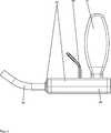
Die
In der Öffnungsvorrichtung ist eine Glasampulle
Der Ampullenkopf
Die Feder
Der Raum
Damit der abgebrochene Ampullenkopf
Das Vakuummischsystem weist einen Standfuß
Die Monomerflüssigkeit kann in der geschlossenen Glasampulle
Der Stößel
Die
In die Öffnungsvorrichtung ist ein Folienbeutel
Direkt neben der Folie
Der Hohldorn
Wenn die Sicherung
Die Öffnungsvorrichtung weist zwei Platten
Mit einer Sicherung (nicht gezeigt) oder mit drei voneinander unabhängigen Sicherungen (nicht gezeigt) werden die Federn
Die in der voranstehenden Beschreibung, sowie den Ansprüchen, Figuren und Ausführungsbeispielen offenbarten Merkmale der Erfindung können sowohl einzeln, als auch in jeder beliebigen Kombination für die Verwirklichung der Erfindung in ihren verschiedenen Ausführungsformen wesentlich sein.The features of the invention disclosed in the foregoing description, as well as the claims, figures and embodiments may be essential both individually and in any combination for the realization of the invention in its various embodiments.
BezugszeichenlisteLIST OF REFERENCE NUMBERS
- 11
- Glasampulle / MonomerflüssigkeitsbehälterGlass ampoule / monomer liquid container
- 22
- Gefäßvessel
- 33
- Deckelcover
- 44
- Ampullenkopfampoule tip
- 66
- Halterungbracket
- 77
- Raum zum Auffangen des AmpullenkopfsSpace for collecting the ampoule head
- 88th
- Stößel / ÖffnungseinrichtungPlunger / opening device
- 99
- Feder / elastisches EnergiespeicherelementSpring / elastic energy storage element
- 1212
- Deformierbare WandungDeformable wall
- 1414
- Gerüstframework
- 1616
- Sicherungsstift / SicherungLocking pin / fuse
- 1818
- Rohrstutzenpipe socket
- 2020
- Leitung / LeitungsmittelLine / line
- 2222
- Sieb / FilterSieve / filter
- 2323
- Auffangwannedrip tray
- 2424
- Standfuß / FußteilBase / foot part
- 2626
- Ausnehmungrecess
- 3131
- Folienbeutel / MonomerflüssigkeitsbehälterFoil bag / monomer liquid container
- 3434
- FolienbeutelkopfFoil pouch head
- 3535
- Foliefoil
- 3636
- Halterungbracket
- 3737
- Raum im FolienbeutelkopfSpace in the foil bag head
- 3838
- Hohldorn / ÖffnungseinrichtungHollow mandrel / opening device
- 3939
- Feder / elastisches EnergiespeicherelementSpring / elastic energy storage element
- 4444
- Gehäusecasing
- 4646
- Sicherungfuse
- 4848
- Rohrstutzenpipe socket
- 5050
- Schlauch / LeitungsmittelHose / conduit
- 5656
- Ausnehmungrecess
- 5858
- Ausnehmungrecess
- 6161
- Ampulleampoule
- 6464
- Ampullenkopfampoule tip
- 6565
- SollbruchstelleBreaking point
- 6767
- Platte / ÖffnungseinrichtungPlate / opening device
- 6868
- Stößel mit Kante / ÖffnungseinrichtungTappet with edge / opening device
- 6969
- Federfeather
ZITATE ENTHALTEN IN DER BESCHREIBUNG QUOTES INCLUDE IN THE DESCRIPTION
Diese Liste der vom Anmelder aufgeführten Dokumente wurde automatisiert erzeugt und ist ausschließlich zur besseren Information des Lesers aufgenommen. Die Liste ist nicht Bestandteil der deutschen Patent- bzw. Gebrauchsmusteranmeldung. Das DPMA übernimmt keinerlei Haftung für etwaige Fehler oder Auslassungen.This list of the documents listed by the applicant has been generated automatically and is included solely for the better information of the reader. The list is not part of the German patent or utility model application. The DPMA assumes no liability for any errors or omissions.
Zitierte PatentliteraturCited patent literature
- US 6033105 A[0006]US 6033105 A[0006]
- US 5624184 A[0006]US 5624184 A[0006]
- US 4671263 A[0006]US 4671263 A[0006]
- US 4973168 A[0006]US 4973168 A[0006]
- US 5100241 A[0006]US 5,100,241 A[0006]
- WO 99/67015 A1[0006]WO 99/67015 Al[0006]
- EP 1020167 A2[0006]EP 1020167 A2[0006]
- US 5586821 A[0006]US 5586821 A[0006]
- EP 1016452 A2[0006]EP 1016452 A2[0006]
- DE 3640279 A1[0006]DE 3640279 A1[0006]
- WO 94/26403 A1[0006]WO 94/26403 A1[0006]
- EP 1005901 A2[0006]EP 1005901 A2[0006]
- US 5344232 A[0006]US 5344232 A[0006]
- EP 0692229 A1[0007]EP 0692229 A1[0007]
- DE 102009031178 B3[0007, 0008]DE 102009031178 B3[0007, 0008]
- US 5997544 A[0007]US 5997544 A[0007]
- US 6709149 B1[0007]US 6709149 B1[0007]
- DE 69812726 T2[0007]DE 69812726 T2[0007]
- US 5588745 A[0007]US 5588745A[0007]
- WO 2010/012114 A1[0009]WO 2010/012114 A1[0009]
Claims (17)
Translated fromGermanPriority Applications (7)
| Application Number | Priority Date | Filing Date | Title |
|---|---|---|---|
| DE102014112043.4ADE102014112043A1 (en) | 2014-08-22 | 2014-08-22 | Tensioned opening device for monomer containers |
| EP15178674.6AEP2987765B1 (en) | 2014-08-22 | 2015-07-28 | Tensioned opening device for monomer container |
| AU2015207950AAU2015207950B2 (en) | 2014-08-22 | 2015-07-31 | Tensioned opening device for monomer container |
| CA2899539ACA2899539C (en) | 2014-08-22 | 2015-08-05 | Tensioned opening device for monomer container |
| US14/827,544US10485598B2 (en) | 2014-08-22 | 2015-08-17 | Tensioned opening device for monomer container |
| CN201510516907.8ACN105384129B (en) | 2014-08-22 | 2015-08-21 | Tension type opening device for monomer container |
| JP2015164272AJP6204421B2 (en) | 2014-08-22 | 2015-08-21 | Tensioned opening device for monomer containers |
Applications Claiming Priority (1)
| Application Number | Priority Date | Filing Date | Title |
|---|---|---|---|
| DE102014112043.4ADE102014112043A1 (en) | 2014-08-22 | 2014-08-22 | Tensioned opening device for monomer containers |
Publications (1)
| Publication Number | Publication Date |
|---|---|
| DE102014112043A1true DE102014112043A1 (en) | 2016-02-25 |
Family
ID=53794028
Family Applications (1)
| Application Number | Title | Priority Date | Filing Date |
|---|---|---|---|
| DE102014112043.4ACeasedDE102014112043A1 (en) | 2014-08-22 | 2014-08-22 | Tensioned opening device for monomer containers |
Country Status (7)
| Country | Link |
|---|---|
| US (1) | US10485598B2 (en) |
| EP (1) | EP2987765B1 (en) |
| JP (1) | JP6204421B2 (en) |
| CN (1) | CN105384129B (en) |
| AU (1) | AU2015207950B2 (en) |
| CA (1) | CA2899539C (en) |
| DE (1) | DE102014112043A1 (en) |
Families Citing this family (17)
| Publication number | Priority date | Publication date | Assignee | Title |
|---|---|---|---|---|
| DE102010026497B4 (en)* | 2010-07-07 | 2014-04-03 | Heraeus Medical Gmbh | Vakuumzementiersystem |
| US9549770B2 (en) | 2013-10-10 | 2017-01-24 | Biomet Sas | Vacuum indicator system that avoid release without the proper vacuum level |
| DE102016106261B4 (en)* | 2016-04-06 | 2018-03-15 | Heraeus Medical Gmbh | Device for mixing and storing polymethyl methacrylate bone cement with pressure pump and vial breaker |
| CN107128862A (en)* | 2017-07-18 | 2017-09-05 | 龚艳芳 | A kind of medical glass ampoule opener |
| CN107161929A (en)* | 2017-07-18 | 2017-09-15 | 王中杰 | Ampoule bottle bottle opening device |
| CN107161927A (en)* | 2017-07-18 | 2017-09-15 | 王中杰 | A kind of medical ampoule bottle opening scoring devices |
| CN107176576A (en)* | 2017-07-18 | 2017-09-19 | 王中杰 | Medical ampoule bottle opener |
| DE102017125592B4 (en)* | 2017-11-02 | 2019-06-19 | Heraeus Medical Gmbh | Powder-liquid bone cement mixer with compressed gas connection |
| DE102017130084B4 (en)* | 2017-12-15 | 2019-06-27 | Heraeus Medical Gmbh | Bone cement mixing device with spacer in a vial holder |
| CN109132978A (en)* | 2018-06-26 | 2019-01-04 | 王行德 | A kind of medical ampoule bottle bottle opening device |
| CN109748223B (en)* | 2019-03-21 | 2024-06-14 | 上海俊曦生物科技有限公司 | Ampoule bottle opener |
| CN110950285A (en)* | 2019-11-26 | 2020-04-03 | 常州海斯卡智能护理技术有限公司 | Linear bottle breaking device |
| CN111422804B (en)* | 2020-03-30 | 2021-11-05 | 广东省第二人民医院(广东省卫生应急医院) | Automatic opening system for ampoule bottle neck |
| CN114177966B (en)* | 2021-11-20 | 2023-08-04 | 北京新羿生物科技有限公司 | Cover opening and closing device for liquid storage soft rubber tube |
| EP4385613A1 (en) | 2022-12-13 | 2024-06-19 | Heraeus Medical GmbH | Device for mixing bone cement |
| EP4474337A1 (en)* | 2023-06-06 | 2024-12-11 | Heraeus Medical GmbH | Device and method for dispensing a liquid starting component of a bone cement paste |
| EP4474042A1 (en)* | 2023-06-06 | 2024-12-11 | Heraeus Medical GmbH | Mixing system with side ampoule breaker |
Citations (21)
| Publication number | Priority date | Publication date | Assignee | Title |
|---|---|---|---|---|
| DE420352C (en)* | 1924-09-26 | 1925-10-22 | Felix Meyer | Device for the indirect shattering of a tube enclosed in an outer cover by shock |
| US3892237A (en)* | 1973-07-17 | 1975-07-01 | Maurice Steiner | Self-injecting syringe |
| DE2519306A1 (en)* | 1974-04-30 | 1975-11-13 | Du Pont Canada | DEVICE FOR DISPENSING LIQUID PACKED IN A PLASTIC BAG INTO A RECEPTION VESSEL |
| DE3045559C2 (en)* | 1980-12-03 | 1982-10-14 | Kernforschungsanlage Jülich GmbH, 5170 Jülich | Device for opening radiation ampoules |
| US4671263A (en) | 1984-07-11 | 1987-06-09 | Klaus Draenert | Device and process for mixing and applying bone cement |
| DE3640279A1 (en) | 1985-12-23 | 1987-06-25 | Mit Ab | DEVICE FOR MIXING BONE CEMENT IN A VACUUM |
| US4973168A (en) | 1989-01-13 | 1990-11-27 | Chan Kwan Ho | Vacuum mixing/bone cement cartridge and kit |
| US5344232A (en) | 1991-09-30 | 1994-09-06 | Stryker Corporation | Bone cement mixing and loading apparatus |
| WO1994026403A1 (en) | 1993-05-10 | 1994-11-24 | Cemvac System Ab | Method and device for feeding components for bone cement into a mixing vessel for these |
| EP0692229A1 (en) | 1994-07-16 | 1996-01-17 | MERCK PATENT GmbH | Mixing and dispensing device for bone cement |
| US5586821A (en) | 1995-10-10 | 1996-12-24 | Zimmer, Inc. | Bone cement preparation kit |
| US5588745A (en) | 1994-09-02 | 1996-12-31 | Howmedica | Methods and apparatus for mixing bone cement components using an evacuated mixing chamber |
| US5997544A (en) | 1997-05-02 | 1999-12-07 | Merck Patent Gesellschaft Mit Beschrankter Haftung | Process and device for producing sterile-packed bone cement |
| WO1999067015A1 (en) | 1997-05-21 | 1999-12-29 | Nikomed Aps | An apparatus for preparing bone cement |
| US6033105A (en) | 1996-11-15 | 2000-03-07 | Barker; Donald | Integrated bone cement mixing and dispensing system |
| EP1005901A2 (en) | 1995-11-13 | 2000-06-07 | Cemvac System Aktiebolag | Method and device for mixing components for bone cement in a mixing vessel |
| EP1020167A2 (en) | 1999-01-14 | 2000-07-19 | Bristol-Myers Squibb Company | Apparatus and method for mixing and dispensing bone cement |
| DE69812726T2 (en) | 1998-12-14 | 2004-02-05 | Ao Research Institute | METHOD AND DEVICE FOR PRODUCING BONE CEMENT |
| WO2010012114A1 (en) | 2008-07-29 | 2010-02-04 | Medmix Systems Ag | Device for opening a closed fluid container |
| DE102009031178B3 (en) | 2009-06-29 | 2010-09-16 | Heraeus Medical Gmbh | Device for mixing and delivering bone cement |
| DE102011119377B3 (en)* | 2011-11-25 | 2013-04-04 | Heraeus Medical Gmbh | Storage and mixing device for bone cement |
Family Cites Families (11)
| Publication number | Priority date | Publication date | Assignee | Title |
|---|---|---|---|---|
| GB287172A (en)* | 1927-03-18 | 1928-11-15 | Wilhelm Merck | Device for opening ampoules and sealed glass tubes |
| US2179588A (en)* | 1938-05-05 | 1939-11-14 | Christopher D Thomas | Liquid dispenser |
| US2655767A (en)* | 1950-04-20 | 1953-10-20 | H R Stallbohm | Ampoule cutter |
| NL8105442A (en)* | 1980-12-05 | 1982-07-01 | Praemeta | DEVICE FOR CUTTING THE CUPS OF AMPOULES AND THE LIKE. |
| JPS57122873A (en) | 1980-12-05 | 1982-07-30 | Drooff Heinz | Device for separating head section of ampul |
| US5779356A (en) | 1996-02-21 | 1998-07-14 | Chan; Kwan-Ho | Apparatus and method for mixing first and second components of a bone cement in a vacuum |
| AT406014B (en)* | 1997-12-22 | 2000-01-25 | Avl List Gmbh | DEVICE FOR TAKING A LIQUID FROM A GLASS AMPOULE |
| CN201458698U (en)* | 2009-02-16 | 2010-05-12 | 刘长亮 | Ampoule fast opener |
| DE102010026497B4 (en) | 2010-07-07 | 2014-04-03 | Heraeus Medical Gmbh | Vakuumzementiersystem |
| CN201914910U (en)* | 2011-01-25 | 2011-08-03 | 王丽萍 | Ampoule opener |
| US8931665B2 (en)* | 2012-11-06 | 2015-01-13 | Amit Gold | Multi-compartment apparatus for in-situ mixing of a plurality of components before use |
- 2014
- 2014-08-22DEDE102014112043.4Apatent/DE102014112043A1/ennot_activeCeased
- 2015
- 2015-07-28EPEP15178674.6Apatent/EP2987765B1/ennot_activeNot-in-force
- 2015-07-31AUAU2015207950Apatent/AU2015207950B2/ennot_activeCeased
- 2015-08-05CACA2899539Apatent/CA2899539C/ennot_activeExpired - Fee Related
- 2015-08-17USUS14/827,544patent/US10485598B2/ennot_activeExpired - Fee Related
- 2015-08-21CNCN201510516907.8Apatent/CN105384129B/ennot_activeExpired - Fee Related
- 2015-08-21JPJP2015164272Apatent/JP6204421B2/ennot_activeExpired - Fee Related
Patent Citations (25)
| Publication number | Priority date | Publication date | Assignee | Title |
|---|---|---|---|---|
| DE420352C (en)* | 1924-09-26 | 1925-10-22 | Felix Meyer | Device for the indirect shattering of a tube enclosed in an outer cover by shock |
| US3892237A (en)* | 1973-07-17 | 1975-07-01 | Maurice Steiner | Self-injecting syringe |
| DE2519306A1 (en)* | 1974-04-30 | 1975-11-13 | Du Pont Canada | DEVICE FOR DISPENSING LIQUID PACKED IN A PLASTIC BAG INTO A RECEPTION VESSEL |
| DE3045559C2 (en)* | 1980-12-03 | 1982-10-14 | Kernforschungsanlage Jülich GmbH, 5170 Jülich | Device for opening radiation ampoules |
| US4671263A (en) | 1984-07-11 | 1987-06-09 | Klaus Draenert | Device and process for mixing and applying bone cement |
| DE3640279A1 (en) | 1985-12-23 | 1987-06-25 | Mit Ab | DEVICE FOR MIXING BONE CEMENT IN A VACUUM |
| US4973168A (en) | 1989-01-13 | 1990-11-27 | Chan Kwan Ho | Vacuum mixing/bone cement cartridge and kit |
| US5100241A (en) | 1989-01-13 | 1992-03-31 | Chan Kwan Ho | Vacuum mixing/bone cement cartridge and kit |
| US5344232A (en) | 1991-09-30 | 1994-09-06 | Stryker Corporation | Bone cement mixing and loading apparatus |
| WO1994026403A1 (en) | 1993-05-10 | 1994-11-24 | Cemvac System Ab | Method and device for feeding components for bone cement into a mixing vessel for these |
| EP0692229A1 (en) | 1994-07-16 | 1996-01-17 | MERCK PATENT GmbH | Mixing and dispensing device for bone cement |
| US5588745A (en) | 1994-09-02 | 1996-12-31 | Howmedica | Methods and apparatus for mixing bone cement components using an evacuated mixing chamber |
| US5624184A (en) | 1995-10-10 | 1997-04-29 | Chan; Kwan-Ho | Bone cement preparation kit having a breakable mixing shaft forming an output port |
| US5586821A (en) | 1995-10-10 | 1996-12-24 | Zimmer, Inc. | Bone cement preparation kit |
| EP1016452A2 (en) | 1995-11-13 | 2000-07-05 | Cemvac System Aktiebolag | Method and device for mixing components for bone cement in a mixing vessel |
| EP1005901A2 (en) | 1995-11-13 | 2000-06-07 | Cemvac System Aktiebolag | Method and device for mixing components for bone cement in a mixing vessel |
| US6033105A (en) | 1996-11-15 | 2000-03-07 | Barker; Donald | Integrated bone cement mixing and dispensing system |
| US5997544A (en) | 1997-05-02 | 1999-12-07 | Merck Patent Gesellschaft Mit Beschrankter Haftung | Process and device for producing sterile-packed bone cement |
| WO1999067015A1 (en) | 1997-05-21 | 1999-12-29 | Nikomed Aps | An apparatus for preparing bone cement |
| DE69812726T2 (en) | 1998-12-14 | 2004-02-05 | Ao Research Institute | METHOD AND DEVICE FOR PRODUCING BONE CEMENT |
| US6709149B1 (en) | 1998-12-14 | 2004-03-23 | Ao Research Institute Davos | Method of bone cement preparation |
| EP1020167A2 (en) | 1999-01-14 | 2000-07-19 | Bristol-Myers Squibb Company | Apparatus and method for mixing and dispensing bone cement |
| WO2010012114A1 (en) | 2008-07-29 | 2010-02-04 | Medmix Systems Ag | Device for opening a closed fluid container |
| DE102009031178B3 (en) | 2009-06-29 | 2010-09-16 | Heraeus Medical Gmbh | Device for mixing and delivering bone cement |
| DE102011119377B3 (en)* | 2011-11-25 | 2013-04-04 | Heraeus Medical Gmbh | Storage and mixing device for bone cement |
Also Published As
| Publication number | Publication date |
|---|---|
| CA2899539C (en) | 2017-07-18 |
| CA2899539A1 (en) | 2016-02-22 |
| US10485598B2 (en) | 2019-11-26 |
| AU2015207950B2 (en) | 2016-12-22 |
| US20160051304A1 (en) | 2016-02-25 |
| CN105384129B (en) | 2018-04-03 |
| CN105384129A (en) | 2016-03-09 |
| EP2987765B1 (en) | 2018-09-19 |
| EP2987765A1 (en) | 2016-02-24 |
| AU2015207950A1 (en) | 2016-03-10 |
| JP6204421B2 (en) | 2017-09-27 |
| JP2016043270A (en) | 2016-04-04 |
Similar Documents
| Publication | Publication Date | Title |
|---|---|---|
| DE102014112043A1 (en) | Tensioned opening device for monomer containers | |
| EP2957337B1 (en) | Vacuum mixing system and method for mixing of polymethylmethacrylate bone cement | |
| DE102017104854B4 (en) | Two-part storage and mixing device for producing a bone cement and method for this | |
| EP2730332B1 (en) | Device for mixing and applying a paste-like mass | |
| EP2590597B1 (en) | Vacuum cementation system | |
| EP3662990B1 (en) | Device for mixing a bone cement with a cavity for monomer transfer and process | |
| EP2596857B1 (en) | Storage and mixing device for bone cement | |
| EP3584005B1 (en) | Bone cement applicator with retractable mixing rod and method for producing a bone cement | |
| DE102017107569A1 (en) | Device for storing, mixing and discharging a bone cement and method therefor | |
| DE102016110564B4 (en) | Storage and mixing device for bone cement with pressure pump | |
| EP3505237B1 (en) | Bone cement mixing apparatus and method with spacer in an ampoule holder | |
| DE102018131268A1 (en) | Device for mixing a bone cement with a cavity for monomer transfer | |
| EP3584004A1 (en) | Bone cement applicator with retractable mixing rod and method for producing a bone cement | |
| DE102017125592B4 (en) | Powder-liquid bone cement mixer with compressed gas connection | |
| EP3415226A1 (en) | Bone cement applicator with conduit element and closure holder | |
| EP4063007B1 (en) | Method and device for mixing bone cement with pressure relief | |
| DE102019104020A1 (en) | Bone cement applicator with clampable discharge piston | |
| EP4474042A1 (en) | Mixing system with side ampoule breaker | |
| EP4616938A1 (en) | Bone cement mixing system with a puncture connection and a pumping function | |
| EP4474338A1 (en) | Vial opener with multifunctional piston | |
| EP4616935A1 (en) | Bone cement mixing system with a puncture connection | |
| EP4616936A1 (en) | Bone cement mixing system with a built-in connection and a multifunctional piston | |
| EP4616937A1 (en) | Bone cement mixing system with a puncture connection and multifunctional operation |
Legal Events
| Date | Code | Title | Description |
|---|---|---|---|
| R012 | Request for examination validly filed | ||
| R016 | Response to examination communication | ||
| R002 | Refusal decision in examination/registration proceedings | ||
| R003 | Refusal decision now final |