DE102014111334A1 - Charging plug, charging cable and charging method for an electric vehicle - Google Patents
Charging plug, charging cable and charging method for an electric vehicleDownload PDFInfo
- Publication number
- DE102014111334A1 DE102014111334A1DE102014111334.9ADE102014111334ADE102014111334A1DE 102014111334 A1DE102014111334 A1DE 102014111334A1DE 102014111334 ADE102014111334 ADE 102014111334ADE 102014111334 A1DE102014111334 A1DE 102014111334A1
- Authority
- DE
- Germany
- Prior art keywords
- charging
- charging plug
- ntc1
- plug
- ntc3
- Prior art date
- Legal status (The legal status is an assumption and is not a legal conclusion. Google has not performed a legal analysis and makes no representation as to the accuracy of the status listed.)
- Pending
Links
Images


Classifications
- B—PERFORMING OPERATIONS; TRANSPORTING
- B60—VEHICLES IN GENERAL
- B60L—PROPULSION OF ELECTRICALLY-PROPELLED VEHICLES; SUPPLYING ELECTRIC POWER FOR AUXILIARY EQUIPMENT OF ELECTRICALLY-PROPELLED VEHICLES; ELECTRODYNAMIC BRAKE SYSTEMS FOR VEHICLES IN GENERAL; MAGNETIC SUSPENSION OR LEVITATION FOR VEHICLES; MONITORING OPERATING VARIABLES OF ELECTRICALLY-PROPELLED VEHICLES; ELECTRIC SAFETY DEVICES FOR ELECTRICALLY-PROPELLED VEHICLES
- B60L53/00—Methods of charging batteries, specially adapted for electric vehicles; Charging stations or on-board charging equipment therefor; Exchange of energy storage elements in electric vehicles
- B60L53/60—Monitoring or controlling charging stations
- B—PERFORMING OPERATIONS; TRANSPORTING
- B60—VEHICLES IN GENERAL
- B60L—PROPULSION OF ELECTRICALLY-PROPELLED VEHICLES; SUPPLYING ELECTRIC POWER FOR AUXILIARY EQUIPMENT OF ELECTRICALLY-PROPELLED VEHICLES; ELECTRODYNAMIC BRAKE SYSTEMS FOR VEHICLES IN GENERAL; MAGNETIC SUSPENSION OR LEVITATION FOR VEHICLES; MONITORING OPERATING VARIABLES OF ELECTRICALLY-PROPELLED VEHICLES; ELECTRIC SAFETY DEVICES FOR ELECTRICALLY-PROPELLED VEHICLES
- B60L53/00—Methods of charging batteries, specially adapted for electric vehicles; Charging stations or on-board charging equipment therefor; Exchange of energy storage elements in electric vehicles
- B60L53/10—Methods of charging batteries, specially adapted for electric vehicles; Charging stations or on-board charging equipment therefor; Exchange of energy storage elements in electric vehicles characterised by the energy transfer between the charging station and the vehicle
- B60L53/14—Conductive energy transfer
- B60L53/16—Connectors, e.g. plugs or sockets, specially adapted for charging electric vehicles
- G—PHYSICS
- G01—MEASURING; TESTING
- G01D—MEASURING NOT SPECIALLY ADAPTED FOR A SPECIFIC VARIABLE; ARRANGEMENTS FOR MEASURING TWO OR MORE VARIABLES NOT COVERED IN A SINGLE OTHER SUBCLASS; TARIFF METERING APPARATUS; MEASURING OR TESTING NOT OTHERWISE PROVIDED FOR
- G01D5/00—Mechanical means for transferring the output of a sensing member; Means for converting the output of a sensing member to another variable where the form or nature of the sensing member does not constrain the means for converting; Transducers not specially adapted for a specific variable
- G01D5/12—Mechanical means for transferring the output of a sensing member; Means for converting the output of a sensing member to another variable where the form or nature of the sensing member does not constrain the means for converting; Transducers not specially adapted for a specific variable using electric or magnetic means
- G01D5/14—Mechanical means for transferring the output of a sensing member; Means for converting the output of a sensing member to another variable where the form or nature of the sensing member does not constrain the means for converting; Transducers not specially adapted for a specific variable using electric or magnetic means influencing the magnitude of a current or voltage
- G01D5/142—Mechanical means for transferring the output of a sensing member; Means for converting the output of a sensing member to another variable where the form or nature of the sensing member does not constrain the means for converting; Transducers not specially adapted for a specific variable using electric or magnetic means influencing the magnitude of a current or voltage using Hall-effect devices
- G—PHYSICS
- G01—MEASURING; TESTING
- G01K—MEASURING TEMPERATURE; MEASURING QUANTITY OF HEAT; THERMALLY-SENSITIVE ELEMENTS NOT OTHERWISE PROVIDED FOR
- G01K13/00—Thermometers specially adapted for specific purposes
- H—ELECTRICITY
- H01—ELECTRIC ELEMENTS
- H01R—ELECTRICALLY-CONDUCTIVE CONNECTIONS; STRUCTURAL ASSOCIATIONS OF A PLURALITY OF MUTUALLY-INSULATED ELECTRICAL CONNECTING ELEMENTS; COUPLING DEVICES; CURRENT COLLECTORS
- H01R13/00—Details of coupling devices of the kinds covered by groups H01R12/70 or H01R24/00 - H01R33/00
- H01R13/66—Structural association with built-in electrical component
- H01R13/665—Structural association with built-in electrical component with built-in electronic circuit
- H01R13/6683—Structural association with built-in electrical component with built-in electronic circuit with built-in sensor
- H—ELECTRICITY
- H01—ELECTRIC ELEMENTS
- H01R—ELECTRICALLY-CONDUCTIVE CONNECTIONS; STRUCTURAL ASSOCIATIONS OF A PLURALITY OF MUTUALLY-INSULATED ELECTRICAL CONNECTING ELEMENTS; COUPLING DEVICES; CURRENT COLLECTORS
- H01R2201/00—Connectors or connections adapted for particular applications
- H01R2201/26—Connectors or connections adapted for particular applications for vehicles
- Y—GENERAL TAGGING OF NEW TECHNOLOGICAL DEVELOPMENTS; GENERAL TAGGING OF CROSS-SECTIONAL TECHNOLOGIES SPANNING OVER SEVERAL SECTIONS OF THE IPC; TECHNICAL SUBJECTS COVERED BY FORMER USPC CROSS-REFERENCE ART COLLECTIONS [XRACs] AND DIGESTS
- Y02—TECHNOLOGIES OR APPLICATIONS FOR MITIGATION OR ADAPTATION AGAINST CLIMATE CHANGE
- Y02T—CLIMATE CHANGE MITIGATION TECHNOLOGIES RELATED TO TRANSPORTATION
- Y02T10/00—Road transport of goods or passengers
- Y02T10/60—Other road transportation technologies with climate change mitigation effect
- Y02T10/70—Energy storage systems for electromobility, e.g. batteries
- Y—GENERAL TAGGING OF NEW TECHNOLOGICAL DEVELOPMENTS; GENERAL TAGGING OF CROSS-SECTIONAL TECHNOLOGIES SPANNING OVER SEVERAL SECTIONS OF THE IPC; TECHNICAL SUBJECTS COVERED BY FORMER USPC CROSS-REFERENCE ART COLLECTIONS [XRACs] AND DIGESTS
- Y02—TECHNOLOGIES OR APPLICATIONS FOR MITIGATION OR ADAPTATION AGAINST CLIMATE CHANGE
- Y02T—CLIMATE CHANGE MITIGATION TECHNOLOGIES RELATED TO TRANSPORTATION
- Y02T10/00—Road transport of goods or passengers
- Y02T10/60—Other road transportation technologies with climate change mitigation effect
- Y02T10/7072—Electromobility specific charging systems or methods for batteries, ultracapacitors, supercapacitors or double-layer capacitors
- Y—GENERAL TAGGING OF NEW TECHNOLOGICAL DEVELOPMENTS; GENERAL TAGGING OF CROSS-SECTIONAL TECHNOLOGIES SPANNING OVER SEVERAL SECTIONS OF THE IPC; TECHNICAL SUBJECTS COVERED BY FORMER USPC CROSS-REFERENCE ART COLLECTIONS [XRACs] AND DIGESTS
- Y02—TECHNOLOGIES OR APPLICATIONS FOR MITIGATION OR ADAPTATION AGAINST CLIMATE CHANGE
- Y02T—CLIMATE CHANGE MITIGATION TECHNOLOGIES RELATED TO TRANSPORTATION
- Y02T90/00—Enabling technologies or technologies with a potential or indirect contribution to GHG emissions mitigation
- Y02T90/10—Technologies relating to charging of electric vehicles
- Y02T90/12—Electric charging stations
- Y—GENERAL TAGGING OF NEW TECHNOLOGICAL DEVELOPMENTS; GENERAL TAGGING OF CROSS-SECTIONAL TECHNOLOGIES SPANNING OVER SEVERAL SECTIONS OF THE IPC; TECHNICAL SUBJECTS COVERED BY FORMER USPC CROSS-REFERENCE ART COLLECTIONS [XRACs] AND DIGESTS
- Y02—TECHNOLOGIES OR APPLICATIONS FOR MITIGATION OR ADAPTATION AGAINST CLIMATE CHANGE
- Y02T—CLIMATE CHANGE MITIGATION TECHNOLOGIES RELATED TO TRANSPORTATION
- Y02T90/00—Enabling technologies or technologies with a potential or indirect contribution to GHG emissions mitigation
- Y02T90/10—Technologies relating to charging of electric vehicles
- Y02T90/14—Plug-in electric vehicles
- Y—GENERAL TAGGING OF NEW TECHNOLOGICAL DEVELOPMENTS; GENERAL TAGGING OF CROSS-SECTIONAL TECHNOLOGIES SPANNING OVER SEVERAL SECTIONS OF THE IPC; TECHNICAL SUBJECTS COVERED BY FORMER USPC CROSS-REFERENCE ART COLLECTIONS [XRACs] AND DIGESTS
- Y02—TECHNOLOGIES OR APPLICATIONS FOR MITIGATION OR ADAPTATION AGAINST CLIMATE CHANGE
- Y02T—CLIMATE CHANGE MITIGATION TECHNOLOGIES RELATED TO TRANSPORTATION
- Y02T90/00—Enabling technologies or technologies with a potential or indirect contribution to GHG emissions mitigation
- Y02T90/10—Technologies relating to charging of electric vehicles
- Y02T90/16—Information or communication technologies improving the operation of electric vehicles
Landscapes
- Engineering & Computer Science (AREA)
- Power Engineering (AREA)
- Transportation (AREA)
- Mechanical Engineering (AREA)
- Physics & Mathematics (AREA)
- General Physics & Mathematics (AREA)
- Microelectronics & Electronic Packaging (AREA)
- Electric Propulsion And Braking For Vehicles (AREA)
- Charge And Discharge Circuits For Batteries Or The Like (AREA)
- Details Of Connecting Devices For Male And Female Coupling (AREA)
- Secondary Cells (AREA)
Abstract
Translated fromGerman
Description
Translated fromGermanDie vorliegende Erfindung betrifft einen Ladestecker für ein Elektrofahrzeug nach dem Oberbegriff des Patentanspruchs 1. Die Erfindung betrifft ferner ein Ladekabel mit einem solchen Stecker sowie ein entsprechendes Verfahren zum Laden eines Elektrofahrzeuges.The present invention relates to a charging plug for an electric vehicle according to the preamble of claim 1. The invention further relates to a charging cable with such a plug and a corresponding method for charging an electric vehicle.
Stand der TechnikState of the art
Im Bereich der Elektromobilität sind grundsätzlich Fahrzeuge bekannt, deren Batterie mittels eines öffentlichen Stromnetzes aufgeladen werden kann. Im weltweiten Einsatz gibt es eine Vielzahl hierzu geeigneter Stromnetze, Ladestecker und -kabel, die jeweils unterschiedlichsten Qualitätsstandards genügen und Alterungseinflüssen unterliegen. Auch bestehen unterschiedlichste Anforderungen an die Nutzung dieser Infrastruktur.In the field of electromobility vehicles are known in principle, the battery can be charged by means of a public power grid. Worldwide, there are a large number of power grids, charging plugs and cables that are suitable for this purpose, each of which complies with a wide range of quality standards and is subject to the effects of aging. There are also various requirements for the use of this infrastructure.
Um während des Ladevorgangs eine Überlastung der Infrastrukturkomponenten zu vermeiden, wurde mehrfach vorgeschlagen, Ladestecker mit Temperatursensoren auszurüsten, um den Ladestrom bei Bedarf reduzieren oder abschalten zu können. Exemplarisch für diese Lehre seien die Druckschriften
Vereinzelt wurde auch der Versuch unternommen, den korrekten Sitz des Ladesteckers in der Kupplung oder Buchse durch Verwendung eines Hall-Sensors zu überprüfen. Derartige Ansätze sind etwa aus
Offenbarung der ErfindungDisclosure of the invention
Die Erfindung geht aus von einem Ladestecker und einem Ladeverfahren für ein Elektrofahrzeug gemäß den unabhängigen Ansprüchen.The invention is based on a charging plug and a charging method for an electric vehicle according to the independent claims.
Ein Vorzug dieser Lösung liegt in der eröffneten Möglichkeit, den Temperaturverlauf während des Ladevorgangs unmittelbar zwischen Ladebuchse oder Kupplung und Ladestecker zu erfassen. Eine drohende Überhitzung der Steckverbindung bei unsachgemäßer Nutzung des Ladekabels kann so frühzeitig erkannt und durch Abschaltung oder Stromreduzierung abgewendet werden.An advantage of this solution lies in the possibility of detecting the temperature profile during the charging process directly between the charging socket or the coupling and the charging plug. A threatening overheating of the connector in case of improper use of the charging cable can be detected at an early stage and averted by switching off or power reduction.
Weitere vorteilhafte Ausgestaltungen der Erfindung sind in den abhängigen Patentansprüchen angegeben. So können eine der Ladebuchse zugewandte Leiterplatte zum Montieren der Temperatursensoren und ein von der Leiterplatte getragener Hall-Sensor zum Überprüfen der Steckverbindung vorgesehen sein. Die für die Ladung notwendige elektrische Netzverbindung lässt sich so bereits vor dem eigentlichen Ladevorgang auf grundsätzliche Kompatibilität der beiden Steckerteile abprüfen. Als Temperatursensoren, auch Thermistoren genannt, sind verschiedene Elemente geeignet, beispielsweise NTC-Elemente oder PTC-Elemente.Further advantageous embodiments of the invention are specified in the dependent claims. Thus, a charging socket facing the printed circuit board for mounting the temperature sensors and a printed circuit board worn by the Hall sensor for checking the connector may be provided. The necessary for the charge electrical network connection can thus be checked before the actual charging process for basic compatibility of the two connector parts. As temperature sensors, also called thermistors, various elements are suitable, such as NTC elements or PTC elements.
In einer bevorzugten Ausführungsform mögen thermisch leitende und vollumfassend direkt mit den Kontaktstiften verbundene Kontaktflächen auf der Leiterplatte zum Koppeln der Temperatursensoren an die Kontaktstifte dienen. Die Leiterplatte fungiert somit zugleich als Montageplattform, Anbindung, Verdrahtung und Kontaktstelle für die Temperatur- und Hall-Sensoren. Zusätzlich lassen sich auf ihr weitere Bauteile zwecks Schutzbeschaltung des Ladesteckers montieren.In a preferred embodiment, thermally conductive and fully contact surfaces directly connected to the contact pins on the circuit board may serve to couple the temperature sensors to the contact pins. At the same time, the printed circuit board functions as an assembly platform, connection, wiring and contact point for the temperature and Hall sensors. In addition, it can be mounted on other components for the purpose of protective circuit of the charging connector.
Gemäß einem weiteren Aspekt der Erfindung ist der Ladestecker mittels elektrischer Signalleitungen mit einer sogenannten In-Kabel-Kontrollbox (in-cable control and protective device) verbunden. Diese kann die gemeinsamen Signalleitungen sowohl zum Aktivieren des Hall-Sensors als auch der Temperatursensoren nutzen.According to a further aspect of the invention, the charging plug is connected by means of electrical signal lines to a so-called in-cable control box (in-cable control and protective device). This can use the common signal lines both for activating the Hall sensor and the temperature sensors.
Zusätzlich mag ein von den Kontaktstiften abgesetzter weiterer Temperatursensor zum Erfassen eines umweltbedingten Temperatureinflusses auf den Ladestecker vorgesehen sein. Die vorgeschlagene geometrische Anordnung, etwa an einem mit einem der Kontaktstifte elektrisch verbundenen Schutzleiter-Kontaktteil des Ladesteckers, erlaubt es, in Kombination mit den Sensoren direkt an den Leistungs-Kontaktstiften eine Messung und Bewertung der Temperatur aus Ruhezustand und Umwelteinflüssen wie Sonne oder Temperatur-Umgebung im Vergleich zu dem Temperaturverlauf während eines Ladevorgangs durchzuführen.In addition, a remote from the pins further temperature sensor may be provided for detecting an environmental temperature influence on the charging plug. The proposed geometrical arrangement, for example on a protective conductor contact part of the charging plug which is electrically connected to one of the contact pins, makes it possible, in combination with the sensors directly on the power contact pins, to measure and evaluate the temperature from rest and environmental influences such as the sun or temperature environment compared to the temperature during a charging process.
Ein vorgegebener elektrischer Widerstand zumindest einer der Signalleitungen zum Kodieren eines thermischen Verhaltens des Ladesteckers schließlich ermöglicht es, verschiedenste Stecker- und Gehäusevarianten und deren jeweils unterschiedliches thermisches Verhalten mitsamt entsprechender Kennlinien in der Ladeelektronik abzuspeichern, zuzuordnen und daraus abgeleitete Leistungsreduzierungen oder auch Abschaltungen auszulösen.Finally, a predetermined electrical resistance of at least one of the signal lines for encoding a thermal behavior of the charging plug makes it possible to store and allocate a wide variety of plug and housing variants and their respective different thermal behavior together with corresponding characteristic curves in the charging electronics and to trigger power reductions or shutdowns derived therefrom.
Kurze Beschreibung der ZeichnungenBrief description of the drawings
Ein Ausführungsbeispiel der Erfindung ist in den Zeichnungen dargestellt und wird im Folgenden näher beschrieben.An embodiment of the invention is illustrated in the drawings and will be described in more detail below.
Ausführungsformen der ErfindungEmbodiments of the invention
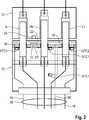
Als Montageplattform der Temperatursensoren NTC1, NTC2, NTC3 fungiert dabei die dem Betrachter der
Weitere, zeichnerisch nicht dargestellte Bauteile können auf der Leiterplatte LP montiert sein, um eine Schutzbeschaltung des Ladesteckers
Der Längsschnitt der
Die Darstellung der
Das Zusammenwirken des Ladesteckers
ZITATE ENTHALTEN IN DER BESCHREIBUNG QUOTES INCLUDE IN THE DESCRIPTION
Diese Liste der vom Anmelder aufgeführten Dokumente wurde automatisiert erzeugt und ist ausschließlich zur besseren Information des Lesers aufgenommen. Die Liste ist nicht Bestandteil der deutschen Patent- bzw. Gebrauchsmusteranmeldung. Das DPMA übernimmt keinerlei Haftung für etwaige Fehler oder Auslassungen.This list of the documents listed by the applicant has been generated automatically and is included solely for the better information of the reader. The list is not part of the German patent or utility model application. The DPMA assumes no liability for any errors or omissions.
Zitierte PatentliteraturCited patent literature
- US 6905362 B2[0003]US 6905362 B2[0003]
- US 8729856 B2[0003]US 8729856 B2[0003]
- US 8573994 B2[0003, 0004]US 8573994 B2[0003, 0004]
- DE 202008009929 U1[0004]DE 202008009929 U1[0004]
Claims (10)
Translated fromGermanPriority Applications (4)
| Application Number | Priority Date | Filing Date | Title |
|---|---|---|---|
| DE102014111334.9ADE102014111334A1 (en) | 2014-08-08 | 2014-08-08 | Charging plug, charging cable and charging method for an electric vehicle |
| CN201510468001.3ACN105375206A (en) | 2014-08-08 | 2015-08-03 | Charging plug, charging cable and charging method for an electric vehicle |
| US14/817,567US9919609B2 (en) | 2014-08-08 | 2015-08-04 | Charging plug, charging cable and charging method for an electric vehicle |
| JP2015155938AJP6059310B2 (en) | 2014-08-08 | 2015-08-06 | Charging plug, charging cable, and charging method for electric vehicle |
Applications Claiming Priority (1)
| Application Number | Priority Date | Filing Date | Title |
|---|---|---|---|
| DE102014111334.9ADE102014111334A1 (en) | 2014-08-08 | 2014-08-08 | Charging plug, charging cable and charging method for an electric vehicle |
Publications (1)
| Publication Number | Publication Date |
|---|---|
| DE102014111334A1true DE102014111334A1 (en) | 2016-02-11 |
Family
ID=55134640
Family Applications (1)
| Application Number | Title | Priority Date | Filing Date |
|---|---|---|---|
| DE102014111334.9APendingDE102014111334A1 (en) | 2014-08-08 | 2014-08-08 | Charging plug, charging cable and charging method for an electric vehicle |
Country Status (4)
| Country | Link |
|---|---|
| US (1) | US9919609B2 (en) |
| JP (1) | JP6059310B2 (en) |
| CN (1) | CN105375206A (en) |
| DE (1) | DE102014111334A1 (en) |
Cited By (19)
| Publication number | Priority date | Publication date | Assignee | Title |
|---|---|---|---|---|
| DE102015106251A1 (en)* | 2015-04-23 | 2016-10-27 | Phoenix Contact E-Mobility Gmbh | Connector part with a temperature monitoring device |
| CN106114273A (en)* | 2016-08-18 | 2016-11-16 | 深圳市华鸿贤精密技术有限公司 | A kind of charging gun |
| DE102016107401A1 (en)* | 2016-02-26 | 2017-08-31 | Amad Mennekes Holding Gmbh & Co. Kg | Plug-in device with temperature detection |
| DE102016211876A1 (en)* | 2016-06-30 | 2018-01-04 | Phoenix Contact E-Mobility Gmbh | Electric connection device with improved thermal coupling of a temperature sensor having a board |
| DE102017212493A1 (en)* | 2017-07-20 | 2018-08-02 | Siemens Aktiengesellschaft | Electrical connector, assembly with an electrical connector, use of an electrical connector and method of operating an electrical connector |
| WO2019068725A1 (en)* | 2017-10-04 | 2019-04-11 | Tmc Sensortechnik Gmbh | ELECTRICAL DATA SHEET |
| DE102017125108A1 (en)* | 2017-10-26 | 2019-05-02 | Phoenix Contact E-Mobility Gmbh | charging plug |
| DE102017011491A1 (en) | 2017-12-13 | 2019-06-13 | Audi Ag | Device for charging a battery with a battery charger |
| DE102018206280A1 (en)* | 2018-04-24 | 2019-10-24 | Te Connectivity Germany Gmbh | ELECTRICAL CONTACT DEVICE, METHOD FOR DETERMINING WEAK CONTACTS, BATTERY CHARGER, AND LOADING DEVICE FOR AN ELECTRIC VEHICLE |
| WO2020070073A1 (en)* | 2018-10-05 | 2020-04-09 | Phoenix Contact E-Mobility Gmbh | Test adapter for testing a temperature sensor system of a connection apparatus |
| DE102018133100A1 (en)* | 2018-12-20 | 2020-06-25 | Lisa Dräxlmaier GmbH | TEMPERATURE DETECTING UNIT FOR A HIGH VOLTAGE CONNECTION AND METHOD FOR PRODUCING A HIGH VOLTAGE CONNECTION |
| EP3724024A1 (en)* | 2017-12-14 | 2020-10-21 | Phoenix Contact e-Mobility GmbH | Temperature-monitored load contact module and cooled charging plug |
| LU101309B1 (en)* | 2019-07-11 | 2021-01-11 | Phoenix Contact E Mobility Gmbh | Electrical assembly with a temperature monitoring device |
| DE102020102219A1 (en) | 2020-01-30 | 2021-08-05 | Audi Aktiengesellschaft | Charging connector for a charging cable for connection to a motor vehicle and motor vehicle and charging system |
| CN114655014A (en)* | 2020-12-23 | 2022-06-24 | 郑州宇通客车股份有限公司 | Electric drive system, safety early warning method and device for electric drive system |
| DE102021101349A1 (en) | 2021-01-22 | 2022-07-28 | Lisa Dräxlmaier GmbH | temperature measuring device |
| DE102022121713A1 (en) | 2022-08-26 | 2024-02-29 | Compleo Charging Solutions Ag | Operating procedure for a utility station and use of a temperature sensor as a theft indicator |
| DE102022122165A1 (en)* | 2022-09-01 | 2024-03-07 | Kiekert Aktiengesellschaft | Electrical circuit for monitoring the respective temperature of a plurality of charging contacts of a charging connector |
| DE102024106982A1 (en)* | 2024-03-12 | 2025-09-18 | Huber Automotive Ag | Method for determining a temperature of a pin; and connector for power transmission |
Families Citing this family (20)
| Publication number | Priority date | Publication date | Assignee | Title |
|---|---|---|---|---|
| DE102014201764A1 (en)* | 2014-01-31 | 2015-08-06 | Siemens Aktiengesellschaft | Electrical connection device and charging cable for an electric vehicle |
| DE102014111831A1 (en)* | 2014-08-19 | 2016-02-25 | Phoenix Contact E-Mobility Gmbh | Connector part with temperature sensors |
| US10116105B2 (en) | 2015-08-21 | 2018-10-30 | Apple Inc. | Illuminated printed circuit boards for connectors |
| US10343539B2 (en)* | 2015-08-31 | 2019-07-09 | Nichicon Corporation | Power supply device for supplying electricity to a load utilizing electric power of a storage-battery-equipped vehicle |
| US20170133792A1 (en)* | 2015-09-30 | 2017-05-11 | Apple Inc. | Connector illumination for insertion in low-light conditions |
| DE102017206094A1 (en)* | 2017-04-10 | 2018-10-11 | BSH Hausgeräte GmbH | Device with a temperature-controlled connector |
| DE102017108526A1 (en)* | 2017-04-21 | 2018-10-25 | Phoenix Contact E-Mobility Gmbh | Charging plug for a motor vehicle and load contact module for a charging plug |
| DE102017222541A1 (en)* | 2017-12-13 | 2019-06-13 | Bayerische Motoren Werke Aktiengesellschaft | High-voltage connector part for a high-voltage connector of a motor vehicle, high-voltage vehicle electrical system and motor vehicle |
| US20190375299A1 (en)* | 2018-06-06 | 2019-12-12 | Ford Global Technologies, Llc | Dual temperature-monitoring hev charger cord and adapter assembly |
| BE1026857B1 (en)* | 2018-12-10 | 2020-07-13 | Phoenix Contact E Mobility Gmbh | Connector part with a circuit board |
| US11506541B2 (en) | 2019-01-03 | 2022-11-22 | Aptiv Technologies Limited | Temperature monitoring device |
| US11285827B2 (en) | 2019-02-06 | 2022-03-29 | Ford Global Technologies, Llc | EV fast charging cord and receptacle |
| NO20190387A1 (en)* | 2019-03-22 | 2020-09-23 | Easee As | Circuit board for an electric vehicle charging station |
| US20230170653A1 (en)* | 2020-05-01 | 2023-06-01 | Eaton Intelligent Power Limited | System of cable and connectors with integrated sensors |
| US11472301B2 (en)* | 2020-08-10 | 2022-10-18 | Webasto Charging Systems, Inc. | Method and system for temperature regulation for a portable charger |
| KR102715364B1 (en)* | 2020-10-20 | 2024-10-08 | 주식회사 엘지에너지솔루션 | A connector with built-in a cooling fan |
| CN114976495B (en)* | 2021-02-19 | 2025-08-12 | 三星Sdi株式会社 | Thermal protection of connectors |
| DE102021123321A1 (en)* | 2021-09-09 | 2023-03-09 | Audi Aktiengesellschaft | Charging cable with charging plug |
| CN113884202A (en)* | 2021-10-28 | 2022-01-04 | 南京康尼新能源汽车零部件有限公司 | Electric automobile charge-discharge interface temperature monitoring device |
| CN115149617A (en)* | 2022-07-22 | 2022-10-04 | 江苏芯云电子科技有限公司 | A monitoring device and protection circuit for connectors |
Citations (9)
| Publication number | Priority date | Publication date | Assignee | Title |
|---|---|---|---|---|
| WO2002013330A1 (en)* | 2000-08-04 | 2002-02-14 | Manfred Fladung Gmbh | Electrical plug connector |
| US6905362B2 (en) | 2000-07-28 | 2005-06-14 | Roger C. Williams | Electric vehicle battery rapid charging connector |
| US20090251832A1 (en)* | 2008-04-07 | 2009-10-08 | Technology Research Corporation | Over heating detection and interrupter circuit |
| DE202008009929U1 (en) | 2008-07-23 | 2009-12-10 | Rema Lipprandt Gmbh & Co. Kg | Charging plug device for motor vehicles with electric drive |
| US8573994B2 (en) | 2010-11-19 | 2013-11-05 | Delphi Technologies, Inc. | Connector handle for an electric vehicle battery charger |
| DE102012107902A1 (en)* | 2012-08-28 | 2014-03-06 | Lapp Engineering & Co. | Plug unit and electrical device with such a plug unit |
| US20140073189A1 (en)* | 2012-09-11 | 2014-03-13 | Panasonic Corporation | Power cord |
| US8729856B2 (en) | 2011-02-23 | 2014-05-20 | Lear Corporation | Thermal wall plug sensing and control |
| WO2014208654A1 (en)* | 2013-06-27 | 2014-12-31 | 矢崎総業株式会社 | Terminal and charging connector |
Family Cites Families (11)
| Publication number | Priority date | Publication date | Assignee | Title |
|---|---|---|---|---|
| JP2002352635A (en) | 2001-05-24 | 2002-12-06 | Hitachi Information Technology Co Ltd | Power cord with temperature sensor |
| CN2775887Y (en)* | 2004-07-28 | 2006-04-26 | 明纬仪电股份有限公司 | Plug with power and energy display device |
| JP2010110055A (en)* | 2008-10-28 | 2010-05-13 | Panasonic Electric Works Co Ltd | Charging cable for electric vehicle |
| DE102009034886A1 (en)* | 2009-07-27 | 2011-02-03 | Rwe Ag | Charging cable plug for connecting an electric vehicle to a charging station |
| FR2977390B1 (en) | 2011-06-29 | 2013-10-11 | Legrand France | ELECTRICAL PLUG AND ELECTRICAL ASSEMBLY THEREFOR. |
| US20130134933A1 (en)* | 2011-11-29 | 2013-05-30 | Delphi Technologies, Inc. | Power safety system and method having a plurality of thermally-triggered electrical breaking arrangements |
| JP2013134927A (en)* | 2011-12-27 | 2013-07-08 | Fujitsu Component Ltd | Distribution gear |
| JP5925534B2 (en)* | 2012-03-09 | 2016-05-25 | パナソニックIpマネジメント株式会社 | power cable |
| AU2013308938A1 (en) | 2012-08-27 | 2015-03-12 | Aerovironment, Inc. | Portable electric vehicle supply equipment |
| CN103001073B (en)* | 2012-10-31 | 2016-01-13 | 钱加灿 | A kind of plug with attemperating unit |
| DE102014111185A1 (en)* | 2014-08-06 | 2016-02-11 | Phoenix Contact E-Mobility Gmbh | Connector part with a temperature sensor device |
- 2014
- 2014-08-08DEDE102014111334.9Apatent/DE102014111334A1/enactivePending
- 2015
- 2015-08-03CNCN201510468001.3Apatent/CN105375206A/enactivePending
- 2015-08-04USUS14/817,567patent/US9919609B2/enactiveActive
- 2015-08-06JPJP2015155938Apatent/JP6059310B2/enactiveActive
Patent Citations (9)
| Publication number | Priority date | Publication date | Assignee | Title |
|---|---|---|---|---|
| US6905362B2 (en) | 2000-07-28 | 2005-06-14 | Roger C. Williams | Electric vehicle battery rapid charging connector |
| WO2002013330A1 (en)* | 2000-08-04 | 2002-02-14 | Manfred Fladung Gmbh | Electrical plug connector |
| US20090251832A1 (en)* | 2008-04-07 | 2009-10-08 | Technology Research Corporation | Over heating detection and interrupter circuit |
| DE202008009929U1 (en) | 2008-07-23 | 2009-12-10 | Rema Lipprandt Gmbh & Co. Kg | Charging plug device for motor vehicles with electric drive |
| US8573994B2 (en) | 2010-11-19 | 2013-11-05 | Delphi Technologies, Inc. | Connector handle for an electric vehicle battery charger |
| US8729856B2 (en) | 2011-02-23 | 2014-05-20 | Lear Corporation | Thermal wall plug sensing and control |
| DE102012107902A1 (en)* | 2012-08-28 | 2014-03-06 | Lapp Engineering & Co. | Plug unit and electrical device with such a plug unit |
| US20140073189A1 (en)* | 2012-09-11 | 2014-03-13 | Panasonic Corporation | Power cord |
| WO2014208654A1 (en)* | 2013-06-27 | 2014-12-31 | 矢崎総業株式会社 | Terminal and charging connector |
Cited By (29)
| Publication number | Priority date | Publication date | Assignee | Title |
|---|---|---|---|---|
| DE102015106251A1 (en)* | 2015-04-23 | 2016-10-27 | Phoenix Contact E-Mobility Gmbh | Connector part with a temperature monitoring device |
| US10530101B2 (en) | 2015-04-23 | 2020-01-07 | Phoenix Contact E-Mobility Gmbh | Plug connector part having a temperature-monitoring device |
| DE102016107401A1 (en)* | 2016-02-26 | 2017-08-31 | Amad Mennekes Holding Gmbh & Co. Kg | Plug-in device with temperature detection |
| DE102016211876A1 (en)* | 2016-06-30 | 2018-01-04 | Phoenix Contact E-Mobility Gmbh | Electric connection device with improved thermal coupling of a temperature sensor having a board |
| US10547131B2 (en) | 2016-06-30 | 2020-01-28 | Phoenix Contact E-Mobility Gmbh | Electrical connection apparatus with improved thermal coupling of a printed circuit board which has a temperature sensor |
| CN106114273A (en)* | 2016-08-18 | 2016-11-16 | 深圳市华鸿贤精密技术有限公司 | A kind of charging gun |
| DE102017212493A1 (en)* | 2017-07-20 | 2018-08-02 | Siemens Aktiengesellschaft | Electrical connector, assembly with an electrical connector, use of an electrical connector and method of operating an electrical connector |
| US11984275B2 (en) | 2017-10-04 | 2024-05-14 | Tmc Sensortechnik Gmbh | Electrical mains plug |
| EP4353516A3 (en)* | 2017-10-04 | 2024-06-12 | TMC Sensortechnik GmbH | Electric power plug |
| WO2019068725A1 (en)* | 2017-10-04 | 2019-04-11 | Tmc Sensortechnik Gmbh | ELECTRICAL DATA SHEET |
| DE102017125108A1 (en)* | 2017-10-26 | 2019-05-02 | Phoenix Contact E-Mobility Gmbh | charging plug |
| DE102017011491A1 (en) | 2017-12-13 | 2019-06-13 | Audi Ag | Device for charging a battery with a battery charger |
| DE102017011491B4 (en) | 2017-12-13 | 2022-08-11 | Audi Ag | Device for charging a battery with a battery charger |
| EP3724024A1 (en)* | 2017-12-14 | 2020-10-21 | Phoenix Contact e-Mobility GmbH | Temperature-monitored load contact module and cooled charging plug |
| DE102018206280B4 (en) | 2018-04-24 | 2019-12-12 | Te Connectivity Germany Gmbh | ELECTRICAL CONTACT DEVICE, METHOD FOR DETERMINING WEAK CONTACTS, BATTERY CHARGER, AND LOADING DEVICE FOR AN ELECTRIC VEHICLE |
| DE102018206280A1 (en)* | 2018-04-24 | 2019-10-24 | Te Connectivity Germany Gmbh | ELECTRICAL CONTACT DEVICE, METHOD FOR DETERMINING WEAK CONTACTS, BATTERY CHARGER, AND LOADING DEVICE FOR AN ELECTRIC VEHICLE |
| WO2020070073A1 (en)* | 2018-10-05 | 2020-04-09 | Phoenix Contact E-Mobility Gmbh | Test adapter for testing a temperature sensor system of a connection apparatus |
| DE102018133100A1 (en)* | 2018-12-20 | 2020-06-25 | Lisa Dräxlmaier GmbH | TEMPERATURE DETECTING UNIT FOR A HIGH VOLTAGE CONNECTION AND METHOD FOR PRODUCING A HIGH VOLTAGE CONNECTION |
| DE102018133100B4 (en) | 2018-12-20 | 2025-01-16 | Lisa Dräxlmaier GmbH | TEMPERATURE SENSING UNIT FOR A HIGH-VOLTAGE CONNECTION AND METHOD FOR PRODUCING A HIGH-VOLTAGE CONNECTION |
| LU101309B1 (en)* | 2019-07-11 | 2021-01-11 | Phoenix Contact E Mobility Gmbh | Electrical assembly with a temperature monitoring device |
| WO2021004765A1 (en)* | 2019-07-11 | 2021-01-14 | Phoenix Contact E-Mobility Gmbh | Electric assembly with a temperature monitoring device |
| US12028961B2 (en) | 2019-07-11 | 2024-07-02 | Phoenix Contact E-Mobility Gmbh | Electrical assembly with a temperature monitoring device |
| DE102020102219A1 (en) | 2020-01-30 | 2021-08-05 | Audi Aktiengesellschaft | Charging connector for a charging cable for connection to a motor vehicle and motor vehicle and charging system |
| CN114655014B (en)* | 2020-12-23 | 2023-05-12 | 宇通客车股份有限公司 | Electric drive system, safety early warning method and device of electric drive system |
| CN114655014A (en)* | 2020-12-23 | 2022-06-24 | 郑州宇通客车股份有限公司 | Electric drive system, safety early warning method and device for electric drive system |
| DE102021101349A1 (en) | 2021-01-22 | 2022-07-28 | Lisa Dräxlmaier GmbH | temperature measuring device |
| DE102022121713A1 (en) | 2022-08-26 | 2024-02-29 | Compleo Charging Solutions Ag | Operating procedure for a utility station and use of a temperature sensor as a theft indicator |
| DE102022122165A1 (en)* | 2022-09-01 | 2024-03-07 | Kiekert Aktiengesellschaft | Electrical circuit for monitoring the respective temperature of a plurality of charging contacts of a charging connector |
| DE102024106982A1 (en)* | 2024-03-12 | 2025-09-18 | Huber Automotive Ag | Method for determining a temperature of a pin; and connector for power transmission |
Also Published As
| Publication number | Publication date |
|---|---|
| JP2016039147A (en) | 2016-03-22 |
| US20160039297A1 (en) | 2016-02-11 |
| CN105375206A (en) | 2016-03-02 |
| US9919609B2 (en) | 2018-03-20 |
| JP6059310B2 (en) | 2017-01-11 |
Similar Documents
| Publication | Publication Date | Title |
|---|---|---|
| DE102014111334A1 (en) | Charging plug, charging cable and charging method for an electric vehicle | |
| DE102015206840B4 (en) | Thermally monitored charging device | |
| DE102014201764A1 (en) | Electrical connection device and charging cable for an electric vehicle | |
| DE102014111831A1 (en) | Connector part with temperature sensors | |
| DE102016107401A1 (en) | Plug-in device with temperature detection | |
| DE102007027916A1 (en) | Battery Holder Plug | |
| DE102013110548A1 (en) | Connector part with a resistance coding | |
| DE202012100613U1 (en) | Test plug for charging stations | |
| DE202009013675U1 (en) | Charging plug system | |
| DE202018002686U1 (en) | Connector for disconnecting and connecting at least one electrical contact for charging a battery unit of a motor vehicle | |
| DE102015107053A1 (en) | Connector part with a temperature-dependent switching device | |
| DE102014119276A1 (en) | current sensor | |
| DE112014003362T5 (en) | Electric appliance comprising an electric plug with inviolable reading means, and electrical system with such a device | |
| DE202013101698U1 (en) | PE contact system for device connection systems of electrical devices | |
| DE202006005024U1 (en) | Coded contact pin for electrical plug, used to make detachable connection in socket, has opening at one end for inserted contact connected to lead | |
| DE102008041539A1 (en) | Shunt resistor with evaluation circuit | |
| DE102014019433A1 (en) | Electronic assembly for an electric motor of a single-wheel drive of a motor vehicle, independent wheel drive and motor vehicle | |
| DE102019208076A1 (en) | Inverter unit | |
| WO2019115137A1 (en) | High-voltage plug connection part for a high-voltage plug connector of a motor vehicle, high-voltage electrical system, and motor vehicle | |
| DE202019105026U1 (en) | Connection adapter for a drive device | |
| DE102009052353A1 (en) | Contact plug for electrical connection between controller and electrical power supply cable in automobile, has electric safety device with contact section contacting contact end, and another contact section contacting another contact end | |
| EP1921456A2 (en) | Motor vehicle sensor, in particular battery sensor with measuring resistance | |
| DE202012002395U1 (en) | Electrical connector | |
| WO2016131604A1 (en) | High voltage system | |
| DE102015203184A1 (en) | Board-mountable modular surge protection device |
Legal Events
| Date | Code | Title | Description |
|---|---|---|---|
| R163 | Identified publications notified | ||
| R012 | Request for examination validly filed |