DE102014111069A1 - Endoscope and method for mounting an endoscope - Google Patents
Endoscope and method for mounting an endoscopeDownload PDFInfo
- Publication number
- DE102014111069A1 DE102014111069A1DE102014111069.2ADE102014111069ADE102014111069A1DE 102014111069 A1DE102014111069 A1DE 102014111069A1DE 102014111069 ADE102014111069 ADE 102014111069ADE 102014111069 A1DE102014111069 A1DE 102014111069A1
- Authority
- DE
- Germany
- Prior art keywords
- endoscope
- fiber
- fiber bundle
- tube
- lens
- Prior art date
- Legal status (The legal status is an assumption and is not a legal conclusion. Google has not performed a legal analysis and makes no representation as to the accuracy of the status listed.)
- Pending
Links
- 238000000034methodMethods0.000titledescription4
- 239000000835fiberSubstances0.000claimsabstractdescription136
- 230000003287optical effectEffects0.000claimsabstractdescription5
- 239000000463materialSubstances0.000claimsabstractdescription3
- 230000001154acute effectEffects0.000claimsdescription3
- 238000004519manufacturing processMethods0.000claimsdescription2
- 238000005286illuminationMethods0.000abstractdescription8
- 239000013307optical fiberSubstances0.000description32
- 238000005452bendingMethods0.000description8
- 238000005253claddingMethods0.000description8
- 239000000853adhesiveSubstances0.000description3
- 230000001070adhesive effectEffects0.000description3
- 238000003780insertionMethods0.000description2
- 230000037431insertionEffects0.000description2
- BUHVIAUBTBOHAG-FOYDDCNASA-N(2r,3r,4s,5r)-2-[6-[[2-(3,5-dimethoxyphenyl)-2-(2-methylphenyl)ethyl]amino]purin-9-yl]-5-(hydroxymethyl)oxolane-3,4-diolChemical compoundCOC1=CC(OC)=CC(C(CNC=2C=3N=CN(C=3N=CN=2)[C@H]2[C@@H]([C@H](O)[C@@H](CO)O2)O)C=2C(=CC=CC=2)C)=C1BUHVIAUBTBOHAG-FOYDDCNASA-N0.000description1
- 101100293261Mus musculus Naa15 geneProteins0.000description1
- 238000003801millingMethods0.000description1
- 238000005498polishingMethods0.000description1
- 238000007789sealingMethods0.000description1
- 238000003860storageMethods0.000description1
- 230000008719thickeningEffects0.000description1
- 230000007704transitionEffects0.000description1
Images

Classifications
- G—PHYSICS
- G02—OPTICS
- G02B—OPTICAL ELEMENTS, SYSTEMS OR APPARATUS
- G02B23/00—Telescopes, e.g. binoculars; Periscopes; Instruments for viewing the inside of hollow bodies; Viewfinders; Optical aiming or sighting devices
- G02B23/24—Instruments or systems for viewing the inside of hollow bodies, e.g. fibrescopes
- G02B23/2407—Optical details
- G02B23/2461—Illumination
- G02B23/2469—Illumination using optical fibres
- A—HUMAN NECESSITIES
- A61—MEDICAL OR VETERINARY SCIENCE; HYGIENE
- A61B—DIAGNOSIS; SURGERY; IDENTIFICATION
- A61B1/00—Instruments for performing medical examinations of the interior of cavities or tubes of the body by visual or photographical inspection, e.g. endoscopes; Illuminating arrangements therefor
- A61B1/00064—Constructional details of the endoscope body
- A61B1/00071—Insertion part of the endoscope body
- A61B1/0008—Insertion part of the endoscope body characterised by distal tip features
- A61B1/00096—Optical elements
- A—HUMAN NECESSITIES
- A61—MEDICAL OR VETERINARY SCIENCE; HYGIENE
- A61B—DIAGNOSIS; SURGERY; IDENTIFICATION
- A61B1/00—Instruments for performing medical examinations of the interior of cavities or tubes of the body by visual or photographical inspection, e.g. endoscopes; Illuminating arrangements therefor
- A61B1/00064—Constructional details of the endoscope body
- A61B1/0011—Manufacturing of endoscope parts
- A—HUMAN NECESSITIES
- A61—MEDICAL OR VETERINARY SCIENCE; HYGIENE
- A61B—DIAGNOSIS; SURGERY; IDENTIFICATION
- A61B1/00—Instruments for performing medical examinations of the interior of cavities or tubes of the body by visual or photographical inspection, e.g. endoscopes; Illuminating arrangements therefor
- A61B1/00163—Optical arrangements
- A61B1/00174—Optical arrangements characterised by the viewing angles
- A61B1/00179—Optical arrangements characterised by the viewing angles for off-axis viewing
- A—HUMAN NECESSITIES
- A61—MEDICAL OR VETERINARY SCIENCE; HYGIENE
- A61B—DIAGNOSIS; SURGERY; IDENTIFICATION
- A61B1/00—Instruments for performing medical examinations of the interior of cavities or tubes of the body by visual or photographical inspection, e.g. endoscopes; Illuminating arrangements therefor
- A61B1/06—Instruments for performing medical examinations of the interior of cavities or tubes of the body by visual or photographical inspection, e.g. endoscopes; Illuminating arrangements therefor with illuminating arrangements
- A61B1/0605—Instruments for performing medical examinations of the interior of cavities or tubes of the body by visual or photographical inspection, e.g. endoscopes; Illuminating arrangements therefor with illuminating arrangements for spatially modulated illumination
- A—HUMAN NECESSITIES
- A61—MEDICAL OR VETERINARY SCIENCE; HYGIENE
- A61B—DIAGNOSIS; SURGERY; IDENTIFICATION
- A61B1/00—Instruments for performing medical examinations of the interior of cavities or tubes of the body by visual or photographical inspection, e.g. endoscopes; Illuminating arrangements therefor
- A61B1/06—Instruments for performing medical examinations of the interior of cavities or tubes of the body by visual or photographical inspection, e.g. endoscopes; Illuminating arrangements therefor with illuminating arrangements
- A61B1/0623—Instruments for performing medical examinations of the interior of cavities or tubes of the body by visual or photographical inspection, e.g. endoscopes; Illuminating arrangements therefor with illuminating arrangements for off-axis illumination
- A—HUMAN NECESSITIES
- A61—MEDICAL OR VETERINARY SCIENCE; HYGIENE
- A61B—DIAGNOSIS; SURGERY; IDENTIFICATION
- A61B1/00—Instruments for performing medical examinations of the interior of cavities or tubes of the body by visual or photographical inspection, e.g. endoscopes; Illuminating arrangements therefor
- A61B1/06—Instruments for performing medical examinations of the interior of cavities or tubes of the body by visual or photographical inspection, e.g. endoscopes; Illuminating arrangements therefor with illuminating arrangements
- A61B1/07—Instruments for performing medical examinations of the interior of cavities or tubes of the body by visual or photographical inspection, e.g. endoscopes; Illuminating arrangements therefor with illuminating arrangements using light-conductive means, e.g. optical fibres
- G—PHYSICS
- G02—OPTICS
- G02B—OPTICAL ELEMENTS, SYSTEMS OR APPARATUS
- G02B23/00—Telescopes, e.g. binoculars; Periscopes; Instruments for viewing the inside of hollow bodies; Viewfinders; Optical aiming or sighting devices
- G02B23/24—Instruments or systems for viewing the inside of hollow bodies, e.g. fibrescopes
- G02B23/2407—Optical details
- G02B23/2423—Optical details of the distal end
- G02B23/243—Objectives for endoscopes
- G—PHYSICS
- G02—OPTICS
- G02B—OPTICAL ELEMENTS, SYSTEMS OR APPARATUS
- G02B23/00—Telescopes, e.g. binoculars; Periscopes; Instruments for viewing the inside of hollow bodies; Viewfinders; Optical aiming or sighting devices
- G02B23/24—Instruments or systems for viewing the inside of hollow bodies, e.g. fibrescopes
- G02B23/2476—Non-optical details, e.g. housings, mountings, supports
- G—PHYSICS
- G02—OPTICS
- G02B—OPTICAL ELEMENTS, SYSTEMS OR APPARATUS
- G02B23/00—Telescopes, e.g. binoculars; Periscopes; Instruments for viewing the inside of hollow bodies; Viewfinders; Optical aiming or sighting devices
- G02B23/24—Instruments or systems for viewing the inside of hollow bodies, e.g. fibrescopes
- G02B23/26—Instruments or systems for viewing the inside of hollow bodies, e.g. fibrescopes using light guides
Landscapes
- Health & Medical Sciences (AREA)
- Life Sciences & Earth Sciences (AREA)
- Physics & Mathematics (AREA)
- Surgery (AREA)
- Optics & Photonics (AREA)
- Engineering & Computer Science (AREA)
- Biomedical Technology (AREA)
- General Health & Medical Sciences (AREA)
- Pathology (AREA)
- Nuclear Medicine, Radiotherapy & Molecular Imaging (AREA)
- Biophysics (AREA)
- Heart & Thoracic Surgery (AREA)
- Medical Informatics (AREA)
- Molecular Biology (AREA)
- Animal Behavior & Ethology (AREA)
- Radiology & Medical Imaging (AREA)
- Public Health (AREA)
- Veterinary Medicine (AREA)
- Astronomy & Astrophysics (AREA)
- General Physics & Mathematics (AREA)
- Manufacturing & Machinery (AREA)
- Endoscopes (AREA)
- Instruments For Viewing The Inside Of Hollow Bodies (AREA)
Abstract
Translated fromGermanDescription
Translated fromGermanDie Erfindung betrifft ein Endoskop gemäß dem Oberbegriff des Anspruchs 1. Schließlich betrifft die Erfindung ein Verfahren zur Montage eines Endoskops gemäß dem Oberbegriff des Anspruchs 10.The invention relates to an endoscope according to the preamble of claim 1. Finally, the invention relates to a method for assembling an endoscope according to the preamble of
Endoskope dienen zur Beobachtung eines Blickfelds, zu dem typischerweise nur eine kleine Öffnung Zugang ermöglicht. Das Endoskop weist eine Endoskopoptik mit einem Objektiv auf. Die Endoskopoptik kann als eigenständiger Bestandteil des Endoskops ausgebildet sein und in das Endoskop eingesetzt. In Endoskopen werden Lichtleitfasern eingesetzt, um das Blickfeld zu beleuchten. Typischerweise wird hierzu ein Bündel vieler Lichtleitfasern verwendet, also ein Faserbündel, um eine ausreichende Lichtstärke vorzusehen. Die Fasern strahlen an ihrem Endbereich das Licht in einem vergleichsweise großen Winkelbereich ab. Dennoch sollten möglichst alle Fasern mit ihrer (Haupt-)Strahlrichtung auf das Blickfeld ausgerichtet sein. Davon abweichende Fasern sorgen für störende Helligkeitsunterschiede im Blickfeld. Die Fasern erhalten dazu ihre entsprechende Ausrichtung während der Montage der Endoskopoptik. Zur Abdichtung und Fixierung ihrer Ausrichtung werden die Fasern am distalen Endbereich mittels eines Klebstoffs verklebt und anschließend poliert.Endoscopes are used to observe a field of view, to which typically only a small opening allows access. The endoscope has an endoscope optical system with a lens. The endoscope optics can be designed as an independent component of the endoscope and inserted into the endoscope. In endoscopes, optical fibers are used to illuminate the field of view. Typically, for this purpose, a bundle of many optical fibers is used, ie a fiber bundle, in order to provide sufficient light intensity. The fibers emit the light in a comparatively large angular range at their end region. Nevertheless, as far as possible all fibers should be aligned with their (main) beam direction on the field of view. Deviating fibers provide disturbing brightness differences in the field of vision. The fibers receive their appropriate orientation during assembly of the endoscope optics. To seal and fix their orientation, the fibers are glued at the distal end region by means of an adhesive and then polished.
Aus der
Aus der
Die
Nachteilig an den bekannten Endoskopoptiken ist, dass die endgültige Ausrichtung der Lichtleitfasern erst bei der endgültigen Positionierung des Außenrohrs als Umhüllung des Faserrohrs eingestellt wird. Der Zusammenbau ist daher sehr aufwendig und manuell durchzuführen.A disadvantage of the known endoscope optics is that the final alignment of the optical fibers is set only in the final positioning of the outer tube as a cladding of the fiber tube. The assembly is therefore very expensive and manual.
Die Aufgabe der vorliegenden Erfindung besteht darin, ein gattungsgemäßes Endoskop mit das Blickfeld zielgerichtet ausleuchtenden Lichtleitfasern zu schaffen, bei dem der Zusammenbau erleichtert und die Ausrichtung verbessert wird.The object of the present invention is to provide a generic endoscope with the field of view targeted illuminating optical fibers, in which facilitates the assembly and the alignment is improved.
Diese Aufgabe wird durch ein Endoskop mit den Merkmalen des Anspruchs 1 gelöst. Demnach ist der distale Endbereich des Faserbündels in einem distalen Durchbruch im Faserrohr der Endoskopoptik angeordnet. Der Durchbruch ist dabei vorzugsweise rundum von Material des Faserrohrs umgeben, weist also insbesondere einen geschlossenen Rand auf. Dies bedeutet, dass das Faserrohr einen Durchbruch aufweist, in den die Lichtleitfasern eingesteckt werden können. Der Durchbruch durchtritt vorzugsweise eine Wand des Faserrohrs in einem Bereich mit einer Verdickung. Dabei durchtritt der Durchbruch vorzugsweise die Stirnfläche und/oder zumindest einen Teilabschnitt der Stirnfläche des Faserrohrs. Der Durchbruch ist insbesondere zur Aufnahme des gesamten Faserbündels ausgebildet. Durch Einbringen der Lichtleitfasern in den Durchbruch des Faserrohrs erfolgt bereits die Ausrichtung der Fasern, insbesondere deren distaler Endbereiche. Damit wird bereits eine korrekte Ausrichtung der Faserenden nur im Faserrohr erreicht, ohne dass ein Aufschieben des Hüllrohrs erforderlich ist. Die Montage des Endoskops wird somit erheblich erleichtert.This object is achieved by an endoscope with the features of claim 1. Accordingly, the distal end region of the fiber bundle is arranged in a distal opening in the fiber tube of the endoscope optics. The breakthrough is preferably surrounded all around by material of the fiber tube, so in particular has a closed edge. This means that the fiber tube has a breakthrough, in which the optical fibers can be inserted. The aperture preferably passes through a wall of the fiber tube in a region having a thickening. In this case, the opening preferably passes through the end face and / or at least a partial section of the end face of the fiber tube. The breakthrough is designed in particular for receiving the entire fiber bundle. By introducing the optical fibers into the opening of the fiber tube, the orientation of the fibers, in particular their distal end regions, already takes place. Thus, a correct alignment of the fiber ends is achieved only in the fiber tube, without pushing the cladding tube is required. The mounting of the endoscope is thus greatly facilitated.
Die Lichtleitfasern beziehungsweise das Faserbündel sind insbesondere im Durchbruch befestigt. Hierzu können die Lichtleitfasern beispielsweise durch eine Klemmwirkung, durch Reibungskräfte und/oder eine Verkantung befestigt sein. Diese Befestigung dient insbesondere dazu, ein Verrutschen der Lichtleitfasern bei der Montage der Endoskopoptik, insbesondere bei der Montage des Hüllrohrs zu verhindern. Die Befestigung erfolgt weiter bevorzugt dauerhaft. Hierzu kann insbesondere ein Klebstoff oder ähnliches verwendet werden, um so eine dauerhafte Fixierung und Abdichtung zu erreichen.The optical fibers or the fiber bundle are fastened in particular in the opening. For this purpose, the optical fibers can be fixed, for example, by a clamping action, by frictional forces and / or tilting. This attachment is used in particular to prevent slippage of the optical fibers during assembly of the endoscope optics, in particular during assembly of the cladding tube. The attachment is further preferably permanent. For this purpose, in particular an adhesive or the like can be used, so as to achieve a permanent fixation and sealing.
Vorzugsweise ist das Objektiv schräg unter einem Winkel zur Längsmittelachse des Faserrohrs abwärts durch die Öffnung blickend ausgerichtet. Ein solches schräg blickendes Endoskop kann zur Beobachtung eines abseits der Längsmittelachse des Endoskops liegenden Blickfeldes eingesetzt werden. Dies bietet den Vorteil einer optimierten Blickfeldausleuchtung. Gleichzeitig wird eine verbesserte Montage des Endoskops beziehungsweise der Endoskopoptik sichergestellt. Preferably, the lens is obliquely oriented at an angle to the longitudinal central axis of the fiber tube down through the opening. Such an oblique-looking endoscope can be used to observe a field of vision lying away from the longitudinal center axis of the endoscope. This offers the advantage of optimized field of view illumination. At the same time an improved assembly of the endoscope or the endoscope optics is ensured.
Bevorzugt sind die Längsmittelachse des Durchbruchs und die Längsmittelachse des distalen Endes des Faserbündels beziehungsweise der Lichtleitfasern zumindest im Wesentlichen parallel zueinander ausgerichtet. Die Längsmittelachse des distalen Endes des Faserbündels entspricht insbesondere der Strahlrichtung der Lichtleitfasern. Dies bedeutet, dass der Durchbruch die Ausrichtung des distalen Endes der Fasern vorgibt. Durch die parallele oder zumindest nahezu parallele Ausrichtung der Längsmittelachsen von Faserbündel und Blickrichtung des Objektivs wird eine saubere Führung der Fasern ermöglicht. Hierzu muss insbesondere der Durchbruch eine hinreichende Längserstreckung aufweisen, um eine ausreichende Führung des Faserbündels zu erreichen. Vorzugsweise ist demnach der Durchbruch gegenüber der Längsmittelachse des Faserrohrs schräg verlaufend angeordnet.Preferably, the longitudinal center axis of the opening and the longitudinal central axis of the distal end of the fiber bundle or of the optical fibers are aligned at least substantially parallel to one another. The longitudinal central axis of the distal end of the fiber bundle corresponds in particular to the beam direction of the optical fibers. This means that the breakthrough dictates the orientation of the distal end of the fibers. The parallel or at least nearly parallel alignment of the longitudinal center axes of the fiber bundles and the viewing direction of the objective makes it possible to guide the fibers cleanly. For this purpose, in particular the breakthrough must have a sufficient longitudinal extent in order to achieve sufficient guidance of the fiber bundle. Preferably, therefore, the breakthrough opposite the longitudinal central axis of the fiber tube is arranged obliquely.
Weiter bevorzugt weicht die Ausrichtung des Faserbündels, insbesondere dessen Längsmittelachse beziehungsweise Strahlrichtung, von der Längsmittelachse des Durchbruchs ab. Dies kann beispielsweise durch eine Biegung der Fasern hervorgerufen werden. Eine solche Biegung tritt insbesondere bei einer Ausrichtung der Endbereiche der Fasern schräg zur Längserstreckung des Endoskops auf. Die schräge Ausrichtung ist typischerweise zur besseren Ausleuchtung des Blickfelds vorgesehen. Die Biegung der Fasern erfolgt vorzugsweise in einem Biegebereich. Kleine Abweichungen zwischen der Ausrichtung des Durchbruchs und der Faserenden können beispielsweise durch eine Vorspannung ausgeglichen werden.More preferably, the orientation of the fiber bundle, in particular its longitudinal central axis or beam direction, deviates from the longitudinal central axis of the opening. This can be caused for example by a bending of the fibers. Such a bend occurs in particular when the end regions of the fibers are oriented obliquely to the longitudinal extension of the endoscope. The oblique orientation is typically provided for better illumination of the field of view. The bending of the fibers preferably takes place in a bending region. Small deviations between the orientation of the aperture and the fiber ends can be compensated for example by a bias voltage.
Die Längsmittelachse des Durchbruchs und die Blickrichtung des Objektivs beziehungsweise die Längsmittelachse des Faserbündels schließen im Bereich vor dem Objektiv vorzugsweise einen spitzen Winkel ein. Dies bedeutet, dass der Durchbruch beziehungsweise die Fasern etwas stärker schräg gegenüber der Längsmittelachse des Endoskops ausgerichtet sind als das Objektiv beziehungsweise dessen Blickrichtung. Damit wird eine verbesserte Ausrichtung der Fasern in Sollrichtung erreicht. Die Sollrichtung liegt vorzugsweise parallel zur Blickrichtung des Objektivs zur optimalen Ausleuchtung des Blickfeldes, insbesondere in einem Bereich dicht vor dem Objektiv. Insbesondere ist die Hauptrichtung des Durchbruchs schräger ausgerichtet als diejenige des Objektivs. So erhalten die gebogenen Fasern eine optimale Ausrichtung. Dies ist erforderlich, da Lichtleitfasern bei einer gebogenen Anordnung typischerweise von der Idealausrichtung abweichen.The longitudinal central axis of the aperture and the viewing direction of the objective or the longitudinal central axis of the fiber bundle preferably include an acute angle in the region in front of the objective. This means that the aperture or the fibers are aligned somewhat more obliquely with respect to the longitudinal central axis of the endoscope than the objective or its viewing direction. This achieves improved alignment of the fibers in the desired direction. The desired direction is preferably parallel to the viewing direction of the objective for optimal illumination of the field of view, in particular in a region close to the objective. In particular, the main direction of the aperture is aligned obliquely than that of the objective. This gives the bent fibers optimal alignment. This is necessary because optical fibers typically deviate from ideal alignment in a bent configuration.
Bevorzugt beträgt der Winkel zwischen der Längsmittelachse des Durchbruchs beziehungsweise des Faserbündels, insbesondere dessen Strahlrichtung, und der Blickrichtung des Objektivs weniger als 20°, vorzugsweise zwischen 1° und 20°, besonders bevorzugt zwischen 2° und 6°. Eine derart geringe stärkere Neigung genügt in der Regel bereits, um eine entsprechende Rückbiegung der Fasern zu kompensieren. Damit wird eine optimale Ausleuchtung des Blickfelds erreicht.Preferably, the angle between the longitudinal central axis of the aperture or of the fiber bundle, in particular its beam direction, and the viewing direction of the lens is less than 20 °, preferably between 1 ° and 20 °, particularly preferably between 2 ° and 6 °. As a rule, such a small, stronger inclination is already sufficient to compensate for a corresponding bending back of the fibers. This ensures optimum illumination of the field of view.
Weiter bevorzugt ist der Durchbruch zumindest im Wesentlichen als halbrunde oder halbmondförmige Fräsung ausgebildet. Eine solche geometrische Form bietet ein möglichst breites Beleuchtungsfeld bei gleichzeitig optimaler Anpassung an die in der Regel runde äußere Form der Endoskopoptik. Gleichzeitig wird hierbei der zur Verfügung stehende Platz optimal ausgenutzt. Vorzugsweise ist der Durchbruch oberhalb der Optik beziehungsweise des Objektivs vorgesehen.More preferably, the opening is formed at least substantially as a semicircular or crescent-shaped milling. Such a geometric shape offers the widest possible illumination field while optimally adapting to the generally round outer shape of the endoscope optics. At the same time, the available space is optimally utilized. Preferably, the opening is provided above the lens or the lens.
Das Faserbündel endet weiter bevorzugt mit dem distalen Endbereich im Durchbruch. Ebenso kann das Faserbündel bündig mit der Vorderkante des Faserrohrs abschließen. Beide Ausrichtungen führen dazu, dass der distale Endbereich des Faserbündels beziehungsweise der Lichtleitfasern an der optimalen Position angeordnet ist. Gleichzeitig wird ein größtmöglicher Schutz der empfindlichen Stirnfläche der Fasern erreicht.The fiber bundle further preferably ends with the distal end region in the opening. Likewise, the fiber bundle can be flush with the leading edge of the fiber tube. Both orientations lead to the distal end region of the fiber bundle or of the optical fibers being arranged at the optimum position. At the same time the greatest possible protection of the sensitive end face of the fibers is achieved.
Schließlich betrifft die Erfindung ein Verfahren zur Herstellung beziehungsweise Montage eines Endoskops beziehungsweise einer Endoskopoptik für ein Endoskop, wie sie oben beschrieben wurde. Das Verfahren ist durch die folgenden Schritte gekennzeichnet:
- a) das Faserbündel wird endseitig in den Durchbruch im Faserrohr eingeführt,
- b) das Faserrohr wird in das Außenrohr eingeführt, insbesondere zur Fixierung des Faserbündels, und
- c) das Faserbündel wird im Durchbruch verklebt und stirnflächenseitig geschliffen und/oder poliert.
- a) the fiber bundle is inserted into the opening in the fiber tube,
- b) the fiber tube is inserted into the outer tube, in particular for fixing the fiber bundle, and
- c) the fiber bundle is glued in the breakthrough and ground surface side and / or polished.
Eine solche Vorgehensweise vereinfacht die Montage gegenüber dem Stand der Technik erheblich. Hierbei wird das Faserbündel beziehungsweise werden die Lichtleitfasern bereits beim Einführen in den Durchbruch im Faserrohr richtig ausgerichtet. Die Montage des Außenrohrs beziehungsweise Hüllrohrs beeinflusst die Ausrichtung der Fasern praktisch nicht mehr. Allenfalls wird für eine zusätzliche Fixierung des Faserbündels im Bereich zwischen dem Faserrohr und dem Hüllrohr beziehungsweise Außenrohr gesorgt.Such an approach greatly simplifies assembly over the prior art. In this case, the fiber bundle or the optical fibers are already properly aligned during insertion into the opening in the fiber tube. The mounting of the outer tube or cladding tube practically no longer affects the orientation of the fibers. At most it will be for one additional fixation of the fiber bundle in the area between the fiber tube and the cladding tube or outer tube provided.
Grundsätzlich können erfindungsgemäß sowohl geradeaus blickende als auch schräg blickende Endoskope verwendet werden.In principle, both straight-looking and oblique-looking endoscopes can be used according to the invention.
Im Folgenden wird anhand der Figuren der Zeichnungen ein bevorzugtes Ausführungsbeispiel der Erfindung näher beschrieben. Es zeigen:In the following, a preferred embodiment of the invention will be described with reference to the figures of the drawings. Show it:
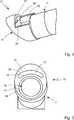
Die Endoskopoptik
Das Hüllrohr beziehungsweise Außenrohr
Die Optik weist im Bereich hinter dem Fenster
Der Lichtaustritt aus dem Faserende
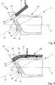
Wie in
Um eine Ausrichtung der Faserenden
Die Lichtleitfasern
Im Stand der Technik ist jedoch die obere Anlagefläche
Erfindungsgemäß sind aber hier sowohl die untere Anlagefläche
Das erfindungsgemäße Verfahren zum Montieren des Endoskopoptik läuft wie folgt: Die Lichtleitfasern
Zum weiteren Zusammenbau werden dann die Lichtleitfasern
Außerdem wird so für eine ortsfeste Lagerung der Lichtleitfasern
Typischerweise bietet der Faserkanal
Die vorstehend beschriebenen Ausführungsbeispiele wie auch weitere erfindungsgemäße Ausführungen können sowohl mit geradeaus als auch mit schräg blickenden Endoskopen verwirklicht werden.The embodiments described above, as well as other embodiments according to the invention can be realized both with straight as well as with oblique-looking endoscopes.
BezugszeichenlisteLIST OF REFERENCE NUMBERS
- 1010
- Endoskopoptikendoscope optics
- 1111
- Faserrohrfiber tube
- 1212
- Außenrohr/HüllrohrOuter tube / cladding tube
- 1313
- LängsmittelachseLongitudinal central axis
- 1414
- Stirnflächeface
- 1515
- Fensteröffnungwindow opening
- 1616
- Fensterwindow
- 1717
- Faserbündelfiber bundles
- 1818
- Faserendefiber end
- 1919
- Stirnflächeface
- 2020
- Strahlrichtungbeam direction
- 2121
- Blickrichtungline of sight
- 2222
- Objektivlens
- 2323
- Biegebereichbending area
- 2424
- Lichtleitfasernoptical fibers
- 2525
- untere Anlageflächelower contact surface
- 2626
- obere Anlageflächeupper contact surface
- 2727
- Durchbruchbreakthrough
- 2828
- Faserkanalfiber channel
ZITATE ENTHALTEN IN DER BESCHREIBUNG QUOTES INCLUDE IN THE DESCRIPTION
Diese Liste der vom Anmelder aufgeführten Dokumente wurde automatisiert erzeugt und ist ausschließlich zur besseren Information des Lesers aufgenommen. Die Liste ist nicht Bestandteil der deutschen Patent- bzw. Gebrauchsmusteranmeldung. Das DPMA übernimmt keinerlei Haftung für etwaige Fehler oder Auslassungen.This list of the documents listed by the applicant has been generated automatically and is included solely for the better information of the reader. The list is not part of the German patent or utility model application. The DPMA assumes no liability for any errors or omissions.
Zitierte PatentliteraturCited patent literature
- DE 102004023024 B4[0003]DE 102004023024 B4[0003]
- US 4850342[0004]US 4850342[0004]
- US 4576147[0005]US 4576147[0005]
Claims (10)
Translated fromGermanPriority Applications (5)
| Application Number | Priority Date | Filing Date | Title |
|---|---|---|---|
| DE102014111069.2ADE102014111069A1 (en) | 2014-08-04 | 2014-08-04 | Endoscope and method for mounting an endoscope |
| US15/329,794US10564410B2 (en) | 2014-08-04 | 2015-07-24 | Endoscope and method for assembling an endoscope |
| EP15762479.2AEP3177198A1 (en) | 2014-08-04 | 2015-07-24 | Endoscope and method for assembling an endoscope |
| PCT/EP2015/001529WO2016020043A1 (en) | 2014-08-04 | 2015-07-24 | Endoscope and method for assembling an endoscope |
| JP2017504409AJP2017528184A (en) | 2014-08-04 | 2015-07-24 | Endoscope and method of assembling the endoscope |
Applications Claiming Priority (1)
| Application Number | Priority Date | Filing Date | Title |
|---|---|---|---|
| DE102014111069.2ADE102014111069A1 (en) | 2014-08-04 | 2014-08-04 | Endoscope and method for mounting an endoscope |
Publications (1)
| Publication Number | Publication Date |
|---|---|
| DE102014111069A1true DE102014111069A1 (en) | 2016-02-04 |
Family
ID=54072780
Family Applications (1)
| Application Number | Title | Priority Date | Filing Date |
|---|---|---|---|
| DE102014111069.2APendingDE102014111069A1 (en) | 2014-08-04 | 2014-08-04 | Endoscope and method for mounting an endoscope |
Country Status (5)
| Country | Link |
|---|---|
| US (1) | US10564410B2 (en) |
| EP (1) | EP3177198A1 (en) |
| JP (1) | JP2017528184A (en) |
| DE (1) | DE102014111069A1 (en) |
| WO (1) | WO2016020043A1 (en) |
Cited By (3)
| Publication number | Priority date | Publication date | Assignee | Title |
|---|---|---|---|---|
| DE102016118102A1 (en) | 2016-09-26 | 2018-03-29 | Henke-Sass, Wolf Gmbh | Endoscope and method for fixing a bundle of optical fibers in a shaft of an endoscope |
| DE102017111306A1 (en) | 2017-05-23 | 2018-11-29 | Karl Storz Se & Co. Kg | endoscope |
| CN114176491A (en)* | 2021-12-22 | 2022-03-15 | 青岛海泰新光科技股份有限公司 | Endoscope optical fiber lighting device capable of improving lighting uniformity |
Families Citing this family (1)
| Publication number | Priority date | Publication date | Assignee | Title |
|---|---|---|---|---|
| US11259694B2 (en)* | 2019-01-31 | 2022-03-01 | Canon U.S.A., Inc. | Window assembly for endoscopic probe |
Citations (6)
| Publication number | Priority date | Publication date | Assignee | Title |
|---|---|---|---|---|
| US4576147A (en) | 1981-07-16 | 1986-03-18 | Olympus Optical Co., Ltd. | Hard endoscope with improved light dispersion |
| US4850342A (en) | 1982-05-01 | 1989-07-25 | Olympus Optical Co., Ltd. | Hard endoscope of oblique view type |
| DE19720163A1 (en)* | 1996-05-16 | 1997-11-20 | Olympus Optical Co | Optical objective system for rigid endoscope with insertion parts of small dia |
| US5700236A (en)* | 1993-10-08 | 1997-12-23 | United States Surgical Corporation | Endoscope attachment for changing angle of view |
| DE102004023024B4 (en) | 2004-05-06 | 2007-03-01 | Olympus Winter & Ibe Gmbh | Endoscope optics with lateral fiber optic bundle |
| DE102013112282A1 (en)* | 2013-11-07 | 2014-01-16 | Karl Storz Gmbh & Co. Kg | Method for manufacturing endoscope used in medical field, involves closing the distal end of lumen within outer shaft after the arrangement of optical devices of observation beam path within outer shaft |
Family Cites Families (11)
| Publication number | Priority date | Publication date | Assignee | Title |
|---|---|---|---|---|
| JPH046513A (en)* | 1990-04-24 | 1992-01-10 | Olympus Optical Co Ltd | Lighting optical system for endoscope |
| JP3012343B2 (en)* | 1991-01-23 | 2000-02-21 | オリンパス光学工業株式会社 | Endoscope system |
| US5305736A (en)* | 1991-04-26 | 1994-04-26 | Asahi Kogaku Kogyo Kabushiki Kaisha | Distal end part of endoscope |
| JP3210404B2 (en)* | 1992-04-15 | 2001-09-17 | 株式会社町田製作所 | Optical fiber binding device |
| JPH07181398A (en)* | 1993-12-24 | 1995-07-21 | Mitsubishi Cable Ind Ltd | Strabismic scope |
| US5782751A (en) | 1994-05-26 | 1998-07-21 | Asahi Kogaku Kogyo Kabushiki Kaisha | Side view endoscope |
| US6004263A (en)* | 1996-03-13 | 1999-12-21 | Hihon Kohden Corporation | Endoscope with detachable operation unit and insertion unit |
| US6248060B1 (en) | 1996-08-12 | 2001-06-19 | Mgb Endoskopische Geraete Gmbh Berlin | Rigid endoscope with second illumination system laterally offset from first illumination system |
| JP4390354B2 (en)* | 2000-04-13 | 2009-12-24 | Hoya株式会社 | Endoscope objective drive mechanism |
| JP2006034543A (en)* | 2004-07-26 | 2006-02-09 | Olympus Corp | Endoscope and repairing method of the same |
| DE102007002042B4 (en)* | 2007-01-13 | 2008-09-18 | Olympus Winter & Ibe Gmbh | Endoscope optic with fiberoptic bundle |
- 2014
- 2014-08-04DEDE102014111069.2Apatent/DE102014111069A1/enactivePending
- 2015
- 2015-07-24JPJP2017504409Apatent/JP2017528184A/enactivePending
- 2015-07-24EPEP15762479.2Apatent/EP3177198A1/ennot_activeWithdrawn
- 2015-07-24WOPCT/EP2015/001529patent/WO2016020043A1/enactiveApplication Filing
- 2015-07-24USUS15/329,794patent/US10564410B2/enactiveActive
Patent Citations (6)
| Publication number | Priority date | Publication date | Assignee | Title |
|---|---|---|---|---|
| US4576147A (en) | 1981-07-16 | 1986-03-18 | Olympus Optical Co., Ltd. | Hard endoscope with improved light dispersion |
| US4850342A (en) | 1982-05-01 | 1989-07-25 | Olympus Optical Co., Ltd. | Hard endoscope of oblique view type |
| US5700236A (en)* | 1993-10-08 | 1997-12-23 | United States Surgical Corporation | Endoscope attachment for changing angle of view |
| DE19720163A1 (en)* | 1996-05-16 | 1997-11-20 | Olympus Optical Co | Optical objective system for rigid endoscope with insertion parts of small dia |
| DE102004023024B4 (en) | 2004-05-06 | 2007-03-01 | Olympus Winter & Ibe Gmbh | Endoscope optics with lateral fiber optic bundle |
| DE102013112282A1 (en)* | 2013-11-07 | 2014-01-16 | Karl Storz Gmbh & Co. Kg | Method for manufacturing endoscope used in medical field, involves closing the distal end of lumen within outer shaft after the arrangement of optical devices of observation beam path within outer shaft |
Cited By (7)
| Publication number | Priority date | Publication date | Assignee | Title |
|---|---|---|---|---|
| DE102016118102A1 (en) | 2016-09-26 | 2018-03-29 | Henke-Sass, Wolf Gmbh | Endoscope and method for fixing a bundle of optical fibers in a shaft of an endoscope |
| EP3305168A1 (en)* | 2016-09-26 | 2018-04-11 | Henke-Sass, Wolf GmbH | Endoscope and method for fixing a bundle of optical conductors in a shaft of an endoscope |
| US10687692B2 (en) | 2016-09-26 | 2020-06-23 | Henke-Sass, Wolf Gmbh | Endoscope and method of securing a bundle of fibre-optic light guides in a shaft of an endoscope |
| DE102017111306A1 (en) | 2017-05-23 | 2018-11-29 | Karl Storz Se & Co. Kg | endoscope |
| EP3415072A3 (en)* | 2017-05-23 | 2019-03-06 | Karl Storz SE & Co. KG | Endoscope |
| US10642021B2 (en) | 2017-05-23 | 2020-05-05 | Karl Storz Se & Co. Kg | Endoscope |
| CN114176491A (en)* | 2021-12-22 | 2022-03-15 | 青岛海泰新光科技股份有限公司 | Endoscope optical fiber lighting device capable of improving lighting uniformity |
Also Published As
| Publication number | Publication date |
|---|---|
| US20170261742A1 (en) | 2017-09-14 |
| WO2016020043A1 (en) | 2016-02-11 |
| EP3177198A1 (en) | 2017-06-14 |
| US10564410B2 (en) | 2020-02-18 |
| JP2017528184A (en) | 2017-09-28 |
Similar Documents
| Publication | Publication Date | Title |
|---|---|---|
| DE19609888B4 (en) | endoscope set | |
| DE3414730A1 (en) | OTOSCOPE AND METHOD FOR THE PRODUCTION THEREOF | |
| DE102008024789A1 (en) | Stereo endoscope | |
| DE3717077A1 (en) | ENDOSCOPE HEAD PIECE | |
| DE102014111069A1 (en) | Endoscope and method for mounting an endoscope | |
| DE3434412A1 (en) | OPTICAL SYSTEM FOR AN ENDOSCOPE FOR CHANGING ITS DIRECTION | |
| WO2015150078A1 (en) | Stereoscopic endoscope system and endoscope, assembly method | |
| DE102014202669A1 (en) | Prism set, prism holder assembly and endoscope with variable viewing direction | |
| EP3697282B1 (en) | Deflection prism assembly for an endoscope and endoscope having a lateral viewing direction | |
| WO2022218932A1 (en) | Handpiece for a flexible endoscope or for a flexible endoscopic instrument | |
| WO2016041637A1 (en) | Endoscope and method for mounting endoscope optics of an endoscope | |
| DE102004023024B4 (en) | Endoscope optics with lateral fiber optic bundle | |
| DE10307904A1 (en) | Endoscope and method for mounting components of an optical system | |
| DE19933526A1 (en) | Light conductor plug connector for endoscope system | |
| DE19850443B4 (en) | Luminaire, in particular for motor vehicles | |
| DE102004009219A1 (en) | Rigid endoscope with fiber image guide | |
| DE102017111306A1 (en) | endoscope | |
| DE19926707A1 (en) | Illumination device for endoscope e.g. electronic endoscope | |
| DE102010056025A1 (en) | Endoscope with a shaft tube | |
| DE102008038619B3 (en) | Endoscope e.g. video endoscope, lens for e.g. providing image on sensor surface of video camera in video endoscope, has middle lens group with planar surface and proximal lens group with plane ring surface, which surrounds concave surface | |
| DE102016118102A1 (en) | Endoscope and method for fixing a bundle of optical fibers in a shaft of an endoscope | |
| DE102012004043A1 (en) | Plug-in connector e.g. linear connector for hollow profiles, has terminal slat structure and non-terminal slat structure that are provided with crescent-shaped auxiliary slats which are formed on one side of associated main plates | |
| DE102015211424A1 (en) | Surgical instrument, in particular ureteroscope | |
| DE10219170B4 (en) | vehicle light | |
| DE4104706C3 (en) | Optical symbol display system |
Legal Events
| Date | Code | Title | Description |
|---|---|---|---|
| R012 | Request for examination validly filed | ||
| R016 | Response to examination communication |