DE102014106939A1 - Electronic assembly for illuminating a target area marking a detection area of a sensor - Google Patents
Electronic assembly for illuminating a target area marking a detection area of a sensorDownload PDFInfo
- Publication number
- DE102014106939A1 DE102014106939A1DE102014106939.0ADE102014106939ADE102014106939A1DE 102014106939 A1DE102014106939 A1DE 102014106939A1DE 102014106939 ADE102014106939 ADE 102014106939ADE 102014106939 A1DE102014106939 A1DE 102014106939A1
- Authority
- DE
- Germany
- Prior art keywords
- electronic assembly
- control
- motor vehicle
- target area
- illumination device
- Prior art date
- Legal status (The legal status is an assumption and is not a legal conclusion. Google has not performed a legal analysis and makes no representation as to the accuracy of the status listed.)
- Withdrawn
Links
- 238000001514detection methodMethods0.000titleclaimsabstractdescription12
- 238000011156evaluationMethods0.000claimsabstractdescription28
- 239000003086colorantSubstances0.000claimsabstractdescription15
- 230000003287optical effectEffects0.000claimsabstractdescription3
- 238000005286illuminationMethods0.000claimsdescription30
- 238000004140cleaningMethods0.000claimsdescription8
- 239000011248coating agentSubstances0.000claimsdescription7
- 238000000576coating methodMethods0.000claimsdescription7
- 239000012530fluidSubstances0.000claimsdescription2
- 230000000712assemblyEffects0.000abstract1
- 238000000429assemblyMethods0.000abstract1
- 239000000758substrateSubstances0.000description4
- 230000008878couplingEffects0.000description2
- 238000010168coupling processMethods0.000description2
- 238000005859coupling reactionMethods0.000description2
- 125000006850spacer groupChemical group0.000description2
- XLYOFNOQVPJJNP-UHFFFAOYSA-NwaterSubstancesOXLYOFNOQVPJJNP-UHFFFAOYSA-N0.000description2
- 230000001419dependent effectEffects0.000description1
- 210000000056organAnatomy0.000description1
- 230000005855radiationEffects0.000description1
- 230000007704transitionEffects0.000description1
- 238000005406washingMethods0.000description1
Images
Classifications
- B—PERFORMING OPERATIONS; TRANSPORTING
- B60—VEHICLES IN GENERAL
- B60Q—ARRANGEMENT OF SIGNALLING OR LIGHTING DEVICES, THE MOUNTING OR SUPPORTING THEREOF OR CIRCUITS THEREFOR, FOR VEHICLES IN GENERAL
- B60Q1/00—Arrangement of optical signalling or lighting devices, the mounting or supporting thereof or circuits therefor
- B60Q1/26—Arrangement of optical signalling or lighting devices, the mounting or supporting thereof or circuits therefor the devices being primarily intended to indicate the vehicle, or parts thereof, or to give signals, to other traffic
- B60Q1/50—Arrangement of optical signalling or lighting devices, the mounting or supporting thereof or circuits therefor the devices being primarily intended to indicate the vehicle, or parts thereof, or to give signals, to other traffic for indicating other intentions or conditions, e.g. request for waiting or overtaking
- B—PERFORMING OPERATIONS; TRANSPORTING
- B60—VEHICLES IN GENERAL
- B60Q—ARRANGEMENT OF SIGNALLING OR LIGHTING DEVICES, THE MOUNTING OR SUPPORTING THEREOF OR CIRCUITS THEREFOR, FOR VEHICLES IN GENERAL
- B60Q1/00—Arrangement of optical signalling or lighting devices, the mounting or supporting thereof or circuits therefor
- B60Q1/26—Arrangement of optical signalling or lighting devices, the mounting or supporting thereof or circuits therefor the devices being primarily intended to indicate the vehicle, or parts thereof, or to give signals, to other traffic
- B60Q1/32—Arrangement of optical signalling or lighting devices, the mounting or supporting thereof or circuits therefor the devices being primarily intended to indicate the vehicle, or parts thereof, or to give signals, to other traffic for indicating vehicle sides, e.g. clearance lights
- B60Q1/323—Arrangement of optical signalling or lighting devices, the mounting or supporting thereof or circuits therefor the devices being primarily intended to indicate the vehicle, or parts thereof, or to give signals, to other traffic for indicating vehicle sides, e.g. clearance lights on or for doors
- B—PERFORMING OPERATIONS; TRANSPORTING
- B08—CLEANING
- B08B—CLEANING IN GENERAL; PREVENTION OF FOULING IN GENERAL
- B08B3/00—Cleaning by methods involving the use or presence of liquid or steam
- B08B3/02—Cleaning by the force of jets or sprays
- B—PERFORMING OPERATIONS; TRANSPORTING
- B60—VEHICLES IN GENERAL
- B60Q—ARRANGEMENT OF SIGNALLING OR LIGHTING DEVICES, THE MOUNTING OR SUPPORTING THEREOF OR CIRCUITS THEREFOR, FOR VEHICLES IN GENERAL
- B60Q1/00—Arrangement of optical signalling or lighting devices, the mounting or supporting thereof or circuits therefor
- B60Q1/02—Arrangement of optical signalling or lighting devices, the mounting or supporting thereof or circuits therefor the devices being primarily intended to illuminate the way ahead or to illuminate other areas of way or environments
- B60Q1/24—Arrangement of optical signalling or lighting devices, the mounting or supporting thereof or circuits therefor the devices being primarily intended to illuminate the way ahead or to illuminate other areas of way or environments for lighting other areas than only the way ahead
- B60Q1/247—Arrangement of optical signalling or lighting devices, the mounting or supporting thereof or circuits therefor the devices being primarily intended to illuminate the way ahead or to illuminate other areas of way or environments for lighting other areas than only the way ahead for illuminating the close surroundings of the vehicle, e.g. to facilitate entry or exit
- F—MECHANICAL ENGINEERING; LIGHTING; HEATING; WEAPONS; BLASTING
- F21—LIGHTING
- F21V—FUNCTIONAL FEATURES OR DETAILS OF LIGHTING DEVICES OR SYSTEMS THEREOF; STRUCTURAL COMBINATIONS OF LIGHTING DEVICES WITH OTHER ARTICLES, NOT OTHERWISE PROVIDED FOR
- F21V5/00—Refractors for light sources
- F21V5/04—Refractors for light sources of lens shape
- H—ELECTRICITY
- H05—ELECTRIC TECHNIQUES NOT OTHERWISE PROVIDED FOR
- H05B—ELECTRIC HEATING; ELECTRIC LIGHT SOURCES NOT OTHERWISE PROVIDED FOR; CIRCUIT ARRANGEMENTS FOR ELECTRIC LIGHT SOURCES, IN GENERAL
- H05B45/00—Circuit arrangements for operating light-emitting diodes [LED]
- H05B45/20—Controlling the colour of the light
- H05B45/22—Controlling the colour of the light using optical feedback
- H—ELECTRICITY
- H05—ELECTRIC TECHNIQUES NOT OTHERWISE PROVIDED FOR
- H05B—ELECTRIC HEATING; ELECTRIC LIGHT SOURCES NOT OTHERWISE PROVIDED FOR; CIRCUIT ARRANGEMENTS FOR ELECTRIC LIGHT SOURCES, IN GENERAL
- H05B47/00—Circuit arrangements for operating light sources in general, i.e. where the type of light source is not relevant
- H05B47/10—Controlling the light source
- H05B47/105—Controlling the light source in response to determined parameters
- H05B47/11—Controlling the light source in response to determined parameters by determining the brightness or colour temperature of ambient light
- B—PERFORMING OPERATIONS; TRANSPORTING
- B60—VEHICLES IN GENERAL
- B60Q—ARRANGEMENT OF SIGNALLING OR LIGHTING DEVICES, THE MOUNTING OR SUPPORTING THEREOF OR CIRCUITS THEREFOR, FOR VEHICLES IN GENERAL
- B60Q2400/00—Special features or arrangements of exterior signal lamps for vehicles
- B60Q2400/20—Multi-color single source or LED matrix, e.g. yellow blinker and red brake lamp generated by single lamp
- B—PERFORMING OPERATIONS; TRANSPORTING
- B60—VEHICLES IN GENERAL
- B60Q—ARRANGEMENT OF SIGNALLING OR LIGHTING DEVICES, THE MOUNTING OR SUPPORTING THEREOF OR CIRCUITS THEREFOR, FOR VEHICLES IN GENERAL
- B60Q2400/00—Special features or arrangements of exterior signal lamps for vehicles
- B60Q2400/40—Welcome lights, i.e. specific or existing exterior lamps to assist leaving or approaching the vehicle
- B—PERFORMING OPERATIONS; TRANSPORTING
- B60—VEHICLES IN GENERAL
- B60Q—ARRANGEMENT OF SIGNALLING OR LIGHTING DEVICES, THE MOUNTING OR SUPPORTING THEREOF OR CIRCUITS THEREFOR, FOR VEHICLES IN GENERAL
- B60Q2400/00—Special features or arrangements of exterior signal lamps for vehicles
- B60Q2400/50—Projected symbol or information, e.g. onto the road or car body
- F—MECHANICAL ENGINEERING; LIGHTING; HEATING; WEAPONS; BLASTING
- F21—LIGHTING
- F21Y—INDEXING SCHEME ASSOCIATED WITH SUBCLASSES F21K, F21L, F21S and F21V, RELATING TO THE FORM OR THE KIND OF THE LIGHT SOURCES OR OF THE COLOUR OF THE LIGHT EMITTED
- F21Y2113/00—Combination of light sources
- F21Y2113/10—Combination of light sources of different colours
- F21Y2113/13—Combination of light sources of different colours comprising an assembly of point-like light sources
- F—MECHANICAL ENGINEERING; LIGHTING; HEATING; WEAPONS; BLASTING
- F21—LIGHTING
- F21Y—INDEXING SCHEME ASSOCIATED WITH SUBCLASSES F21K, F21L, F21S and F21V, RELATING TO THE FORM OR THE KIND OF THE LIGHT SOURCES OR OF THE COLOUR OF THE LIGHT EMITTED
- F21Y2115/00—Light-generating elements of semiconductor light sources
- F21Y2115/10—Light-emitting diodes [LED]
- Y—GENERAL TAGGING OF NEW TECHNOLOGICAL DEVELOPMENTS; GENERAL TAGGING OF CROSS-SECTIONAL TECHNOLOGIES SPANNING OVER SEVERAL SECTIONS OF THE IPC; TECHNICAL SUBJECTS COVERED BY FORMER USPC CROSS-REFERENCE ART COLLECTIONS [XRACs] AND DIGESTS
- Y02—TECHNOLOGIES OR APPLICATIONS FOR MITIGATION OR ADAPTATION AGAINST CLIMATE CHANGE
- Y02B—CLIMATE CHANGE MITIGATION TECHNOLOGIES RELATED TO BUILDINGS, e.g. HOUSING, HOUSE APPLIANCES OR RELATED END-USER APPLICATIONS
- Y02B20/00—Energy efficient lighting technologies, e.g. halogen lamps or gas discharge lamps
- Y02B20/40—Control techniques providing energy savings, e.g. smart controller or presence detection
Landscapes
- Engineering & Computer Science (AREA)
- Mechanical Engineering (AREA)
- General Engineering & Computer Science (AREA)
- Arrangement Of Elements, Cooling, Sealing, Or The Like Of Lighting Devices (AREA)
- Circuit Arrangement For Electric Light Sources In General (AREA)
- Lighting Device Outwards From Vehicle And Optical Signal (AREA)
- Non-Portable Lighting Devices Or Systems Thereof (AREA)
- Arrangements Of Lighting Devices For Vehicle Interiors, Mounting And Supporting Thereof, Circuits Therefore (AREA)
Abstract
Translated fromGermanDescription
Translated fromGermanDie vorliegende Erfindung betrifft eine elektronische Baugruppe für ein Kraftfahrzeug, und insbesondere eine elektronische Baugruppe zum Beleuchten eines einen Detektionsbereich eines Sensors markierenden Zielbereiches.The present invention relates to an electronic assembly for a motor vehicle, and more particularly to an electronic assembly for illuminating a target area marking a detection area of a sensor.
Zur berührungslosen Betätigung einer Tür oder Klappe an einem Kraftfahrzeug ist es üblich, dass ein Benutzer bei definierten Bereichen des Kraftfahrzeuges gewisse Gesten ausführt, um ein Betätigen der Tür oder Klappe zu initiieren. So ist es zum Öffnen der Heckklappe eines Kraftfahrzeuges üblich, dass ein Benutzer den Fuß beispielsweise in den Bereich unter der hinteren Stoßstange führt und dort gegebenenfalls noch eine seitliche Bewegung ausführt.For non-contact operation of a door or flap on a motor vehicle, it is common for a user to perform certain gestures in defined areas of the motor vehicle in order to initiate an actuation of the door or flap. Thus, it is usual for opening the tailgate of a motor vehicle that a user leads the foot, for example, in the area under the rear bumper and there optionally performs a lateral movement.
Um den Detektionsbereich eines das Vorhandensein des Fußes des Bedieners erfassenden Sensors für den Bediener zu kennzeichnen, ist es bekannt, diesen Bereich über ein Beleuchtungsmittel auf dem Untergrund zu markieren, wozu gemäß dem Stand der Technik weißes Licht verwendet wird.In order to mark the detection area of a sensor detecting the presence of the foot of the operator for the operator, it is known to mark this area on the ground by means of an illuminating means, which according to the prior art uses white light.
Insbesondere bei einen unebenem Untergrund, beispielsweise wenn das Kraftfahrzeug auf einer Rasenfläche abgestellt ist, ist ein mit weißem Licht markierter Zielbereich für einen Bediener jedoch nur ausgesprochen schlecht zu erkennen.In particular, in the case of an uneven ground, for example when the motor vehicle is parked on a lawn, however, a target area marked with white light is only extremely badly visible to an operator.
Es ist daher Aufgabe der vorliegenden Erfindung, eine elektronische Baugruppe bereitzustellen, welche eine von einem Benutzer gut wahrnehmbare Kennzeichnung eines Zielbereiches ermöglicht.It is therefore an object of the present invention to provide an electronic assembly which allows a well-perceived by a user identification of a target area.
Die Aufgabe wird erfindungsgemäß gelöst durch eine elektronische Baugruppe nach Anspruch 1. Die erfindungsgemäße elektronische Baugruppe umfasst ein Gehäuse, in welchem eine Steuer- und Auswerteeinrichtung, die mit einer Steuereinrichtung des Kraftfahrzeuges koppelbar ist, angeordnet ist. Die elektronische Baugruppe umfasst ferner eine mit der Steuer- und Auswerteeinrichtung gekoppelte und von dieser ansteuerbare Beleuchtungseinrichtung, mit welcher ein einen Detektionsbereich kennzeichnender Zielbereich außerhalb des Gehäuses durch ein optisches Signal auf dem Untergrund markierbar ist, wobei die Beleuchtungseinrichtung erfindungsgemäß von der Steuer- und Auswerteeinrichtung zum Ausstrahlen von Licht mit unterschiedlichen Farben ansteuerbar ist.The object is achieved by an electronic assembly according to
Es hat sich gezeigt, dass insbesondere bei unebenem Untergrund und bei Verwendung von weißem Licht zur Markierung/Kennzeichnung des Zielbereichs dieser für einen Benutzer nur sehr schwer wahrnehmbar ist. Ist die Beleuchtungseinrichtung erfindungsgemäß zum Ausstrahlen von Licht mit unterschiedlichen Farben ansteuerbar und wird über die Steuer- und Auswerteeinrichtung die Beleuchtungseinrichtung derart angesteuert, dass ein kontinuierlicher Farbwechsel (beispielsweise zwischen grün und rot) stattfindet, kann der Zielbereich auch bei unebenem Untergrund von einem Benutzer leicht erkannt werden, so dass das berührungslose Betätigen beispielsweise der Heckklappe problemlos möglich ist.It has been found that, especially on uneven ground and when using white light for marking / marking the target area, this is very difficult to perceive by a user. If, according to the invention, the illumination device can be activated to emit light with different colors and the illumination device is controlled via the control and evaluation device in such a way that a continuous color change takes place (for example, between green and red), the target area can easily be recognized by a user even on uneven ground be so that the non-contact operating example of the tailgate is easily possible.
Bei einer bevorzugten Ausführungsform der erfindungsgemäßen elektronischen Baugruppe ist die Beleuchtungseinrichtung zum Ausstrahlen von zumindest rotem und grünem Licht ansteuerbar. Es hat sich gezeigt, dass ein Farbwechsel bei einer entsprechenden Farbkombination von einem Benutzer besonders gut wahrnehmbar ist.In a preferred embodiment of the electronic assembly according to the invention, the illumination device can be driven to emit at least red and green light. It has been found that a color change in a corresponding color combination by a user is particularly noticeable.
Damit die Beleuchtungseinrichtung Licht mit unterschiedlichen Farben ausstrahlen kann, muss beispielsweise ein entsprechendes Leuchtmittel, das mehrere Farben ausstrahlen kann, in der Beleuchtungseinrichtung angeordnet sein. Dieses Leuchtmittel ist dann über die Steuer- und Auswerteschaltung so anzusteuern, dass der gewünschte Wechsel zwischen beispielsweise rotem und grünem Licht erreicht wird. Entsprechende Leuchtmittel haben jedoch eine relativ geringe Strahlungsintensität, so dass es bei einer bevorzugten Ausführungsform vorgesehen ist, dass die Beleuchtungseinrichtung zumindest zwei Leuchtmittel aufweist, wobei sich die von den Leuchtmitteln ausgestrahlten Wellenlängenbereiche unterscheiden. Zum Kennzeichnen des Zielbereiches werden dann die Leuchtmittel mit unterschiedlichem Wellenlängenbereich von der Steuer- und Auswerteeinrichtung abwechselnd an- und ausgeschaltet, wobei die Frequenz der Farbwechsel und die Dauer der jeweiligen Leuchtphasen von der Steuer- und Auswerteeinrichtung steuerbar sind.For the lighting device to be able to emit light with different colors, for example, a corresponding lighting means which can emit a plurality of colors must be arranged in the lighting device. This light source is then to control the control and evaluation circuit so that the desired change between, for example, red and green light is achieved. However, corresponding illuminants have a relatively low radiation intensity, so that it is provided in a preferred embodiment that the illumination device has at least two illumination means, wherein the wavelength ranges radiated by the illumination means differ. To identify the target area, the light sources with different wavelength ranges are then switched on and off alternately by the control and evaluation device, the frequency of the color changes and the duration of the respective light phases being controllable by the control and evaluation device.
Bei einer besonders kostengünstigen und stromsparenden Variante ist es vorgesehen, dass die erfindungsgemäße elektronische Baugruppe zumindest zwei LED-Leuchtmittel aufweist, wobei sich die von den LED-Leuchtmitteln ausgestrahlten Wellenlängenbereiche voneinander unterscheiden.In a particularly cost-effective and energy-saving variant, it is provided that the electronic assembly according to the invention comprises at least two LED bulbs, wherein the wavelength ranges emitted by the LED bulbs differ from each other.
Wie bereits angedeutet, ist die Beschaffenheit des Untergrundes, auf welchen der Zielbereich projiziert werden soll, von entscheidender Bedeutung dafür, wie gut ein Benutzer diesen Zielbereich wahrnehmen kann. Bei einer bevorzugten Ausführungsform der erfindungsgemäßen elektronischen Baugruppe umfasst diese einen mit der Steuer- und Auswerteeinrichtung gekoppelten Sensor, mit welchem der Untergrund bei dem Zielbereich erfasst werden kann. Insbesondere kann ermittelt werden, wie der Untergrund im Hinblick auf vorhandene Höhenunterschiede aufgebaut ist, so dass eine an den Untergrund angepasste Ansteuerung der Beleuchtungseinrichtung erfolgen kann.As already indicated, the nature of the terrain on which the target area is to be projected is of crucial importance to how well a user can perceive that target area. In a preferred embodiment of the electronic assembly according to the invention, this comprises a sensor coupled to the control and evaluation device, with which the background can be detected at the target area. In particular, it can be determined how the substrate is constructed with regard to existing height differences, so that a control of the illumination device adapted to the ground can take place.
Ferner kann die erfindungsgemäße elektronische Baugruppe einen (weiteren) Sensor aufweisen, mit welchem die Helligkeit im Detektions- bzw. Zielbereich erfasst werden kann, so dass die Beleuchtungseinrichtung in Abhängigkeit von der Helligkeit optimal angesteuert werden kann. Bei einer entsprechenden Ausführungsform kann die Ansteuerung der Beleuchtungseinrichtung zum Ausstrahlen unterschiedlicher Farben also an die Helligkeitsgegebenheiten angepasst werden, so dass stets eine optimale Markierung des Zielbereiches möglich ist. Furthermore, the electronic assembly according to the invention may comprise a (further) sensor, with which the brightness in the detection or target area can be detected, so that the illumination device can be optimally controlled as a function of the brightness. In a corresponding embodiment, the control of the illumination device for emitting different colors can thus be adapted to the brightness conditions, so that an optimal marking of the target area is always possible.
Die beiden zuvor genannten Sensoren können durch einen kombinierten Sensor realisiert werden, sofern beide Varianten verwendet werden sollen.The two aforementioned sensors can be realized by a combined sensor, if both variants are to be used.
In Abhängigkeit von der Positionierung der elektronischen Baugruppe innerhalb bzw. an dem Kraftfahrzeug unterliegt diese einer mehr oder weniger starken regelmäßigen Verschmutzung, wodurch die Markierung des Zielbereichs auf einen Untergrund behindert wird, da sich Schmutz auf der Beleuchtungseinrichtung absetzen kann.Depending on the positioning of the electronic assembly within or on the motor vehicle, this subject to a more or less strong regular pollution, whereby the marking of the target area is hindered on a substrate, since dirt can settle on the lighting device.
Bei einer bevorzugten Ausführungsform der erfindungsgemäßen elektronischen Baugruppe ist es daher vorgesehen, dass der Beleuchtungseinrichtung eine selbstreinigende Beschichtung zugeordnet ist, und zwar in dem Bereich der Beleuchtungseinrichtung, durch welche das Licht des bzw. der Leuchtmittel aus der Beleuchtungseinrichtung austritt (also im Bereich der freien Apertur). Bei einer selbstreinigenden Beschichtung ist das Oberflächenverhalten gegenüber einer normalen "Beschichtung" so verändert, dass sich Schmutz nur schwer auf der Beschichtung festsetzen kann und bei Kontakt mit Wasser weitgehend von diesem abgewaschen wird.In a preferred embodiment of the electronic assembly according to the invention, it is therefore provided that the illumination device is assigned a self-cleaning coating, in the region of the illumination device through which the light of the or the illuminant emerges from the illumination device (ie in the region of the free aperture ). In a self-cleaning coating, the surface behavior compared to a normal "coating" is changed so that dirt is difficult to settle on the coating and is largely washed off by contact with water.
Alternativ oder zusätzlich ist es bei einer anderen bevorzugten Ausführungsform vorgesehen, dass die elektronische Baugruppe eine (mit der Steuer- und Auswerteeinrichtung gekoppelte) Düsenanordnung umfasst, über welche die Beleuchtungseinrichtung, oder die selbstreinigende Beschichtung, mit einem Reinigungsfluid beaufschlagt werden kann. Dabei kann es sich um mit einer Reinigungslösung versehenes Wasser handeln. Die Düsenanordnung kann in Abhängigkeit von der Zahl der gefahrenen Kilometer aktiviert werden, alternativ wäre es vorstellbar, dass die Düsenanordnung gleichzeitig mit der Betätigung der Wascheinrichtung für die Heckscheibe oder bei einem Ausstieg des Benutzers aktiviert wird.Alternatively or additionally, it is provided in another preferred embodiment that the electronic module comprises a (coupled to the control and evaluation) nozzle assembly, via which the illumination device, or the self-cleaning coating, can be acted upon with a cleaning fluid. This may be water provided with a cleaning solution. The nozzle arrangement may be activated as a function of the number of kilometers driven, alternatively it would be conceivable that the nozzle arrangement is activated simultaneously with the operation of the rear window washing device or when the user leaves the room.
Die Erfindung wird nachfolgend anhand bevorzugter Ausführungsformen erläutert, welche in der beiliegenden Zeichnung dargestellt sind, wobeiThe invention is explained below with reference to preferred embodiments, which are illustrated in the accompanying drawings, wherein
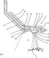
In den beiden Gehäuseabschnitten
In dem Gehäuseabschnitt
Erfindungsgemäß ist die Beleuchtungseinrichtung so ausgebildet, dass diese von der Steuer- und Auswerteschaltung zum Abstrahlen von Licht unterschiedlicher Farben angesteuert werden kann. Dazu umfasst die Beleuchtungseinrichtung beispielsweise zwei Lichtquellen, die entweder Licht unterschiedlicher Wellenlänge bzw. Wellenlängenbereiche ausstrahlen, oder denen jeweils ein entsprechender Filter zugeordnet ist. Damit der Zielbereich von dem Benutzer gut zu erkennen ist, wird das Leuchtmittel
Bei der gezeigten Ausführungsform umfasst die Beleuchtungseinrichtung lediglich ein Leuchtmittel
Bei der gezeigten Ausführungsform umfasst die elektronische Baugruppe ferner einen ersten Sensor
Die elektronische Baugruppe umfasst ferner einen zweiten Sensor
Bei dem ersten Gehäuseabschnitt
Bei der gezeigten Ausführungsform umfasst die elektrische Baugruppe ferner einen zweiten Gehäuseabschnitt
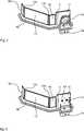
Die
Bei dem zweiten Ausführungsbeispiel sind zwei kapazitive Sensoren
Die Beleuchtungseinrichtung
Bei alternativen Ausführungsformen kann die Beleuchtungseinrichtung eine Mehrzahl von Leuchtmitteln aufweisen, so dass komplexe Farbwechsel zum Kennzeichnen des Zielbereichs verwendet werden können. Eine solche „Lichtorgel“ kann ggf. über die Kopplung der Steuer- und Auswerteeinrichtung mit einer fahrzeuginternen Steuereinrichtung individuell an den Bediener angepasst werden.In alternative embodiments, the illumination device may comprise a plurality of illumination means, so that complex color changes may be used to identify the target area. If necessary, such a "light organ" can be individually adapted to the operator via the coupling of the control and evaluation device with an in-vehicle control device.
Claims (9)
Translated fromGermanPriority Applications (6)
| Application Number | Priority Date | Filing Date | Title |
|---|---|---|---|
| DE102014106939.0ADE102014106939A1 (en) | 2014-05-16 | 2014-05-16 | Electronic assembly for illuminating a target area marking a detection area of a sensor |
| JP2016567078AJP6681842B2 (en) | 2014-05-16 | 2015-03-27 | Electronic assembly for illuminating a target area that marks the detection area of the sensor |
| CN201580022899.XACN106458086B (en) | 2014-05-16 | 2015-03-27 | Electronic assembly for illuminating a target range marking the detection range of a sensor |
| PCT/EP2015/056761WO2015172934A1 (en) | 2014-05-16 | 2015-03-27 | Electronic assembly for illuminating a target area marking a detection area of a sensor |
| US15/311,483US10507762B2 (en) | 2014-05-16 | 2015-03-27 | Electronic assembly for illuminating a target area marking a detection area of a sensor |
| EP15713460.2AEP3142898B1 (en) | 2014-05-16 | 2015-03-27 | Electronic assembly for illuminating a target area marking a detection area of a sensor |
Applications Claiming Priority (1)
| Application Number | Priority Date | Filing Date | Title |
|---|---|---|---|
| DE102014106939.0ADE102014106939A1 (en) | 2014-05-16 | 2014-05-16 | Electronic assembly for illuminating a target area marking a detection area of a sensor |
Publications (1)
| Publication Number | Publication Date |
|---|---|
| DE102014106939A1true DE102014106939A1 (en) | 2015-11-19 |
Family
ID=52781079
Family Applications (1)
| Application Number | Title | Priority Date | Filing Date |
|---|---|---|---|
| DE102014106939.0AWithdrawnDE102014106939A1 (en) | 2014-05-16 | 2014-05-16 | Electronic assembly for illuminating a target area marking a detection area of a sensor |
Country Status (6)
| Country | Link |
|---|---|
| US (1) | US10507762B2 (en) |
| EP (1) | EP3142898B1 (en) |
| JP (1) | JP6681842B2 (en) |
| CN (1) | CN106458086B (en) |
| DE (1) | DE102014106939A1 (en) |
| WO (1) | WO2015172934A1 (en) |
Cited By (2)
| Publication number | Priority date | Publication date | Assignee | Title |
|---|---|---|---|---|
| DE102021115258A1 (en) | 2021-06-14 | 2022-12-15 | Huf Hülsbeck & Fürst Gmbh & Co. Kg | Method for evaluating a sensor device |
| DE102021115259A1 (en) | 2021-06-14 | 2022-12-15 | Huf Hülsbeck & Fürst Gmbh & Co. Kg | Method for evaluating a sensor device |
Families Citing this family (3)
| Publication number | Priority date | Publication date | Assignee | Title |
|---|---|---|---|---|
| JP6483759B2 (en)* | 2017-06-29 | 2019-03-13 | 本田技研工業株式会社 | Working machine |
| JP6606133B2 (en)* | 2017-07-31 | 2019-11-13 | 本田技研工業株式会社 | snowblower |
| EP4470834A1 (en)* | 2023-06-01 | 2024-12-04 | Valeo Vision | Automotive luminous device including a sensor to open a vehicle element |
Family Cites Families (26)
| Publication number | Priority date | Publication date | Assignee | Title |
|---|---|---|---|---|
| US3913840A (en)* | 1974-06-26 | 1975-10-21 | Lawrence Peska Ass Inc | Headlight cleaner for vehicles |
| US5008595A (en)* | 1985-12-18 | 1991-04-16 | Laser Link, Inc. | Ornamental light display apparatus |
| DE4008280A1 (en)* | 1990-03-15 | 1991-09-19 | Tzn Forschung & Entwicklung | Indicating ice etc. on road surface - using IR detector and halogen lamp source with beam modulator and narrow bandpass filter |
| US5243185A (en)* | 1992-07-31 | 1993-09-07 | Loral Aerospace Corp. | Apparatus and method for ice detection |
| WO1995001549A1 (en)* | 1993-06-29 | 1995-01-12 | Omron Corporation | Road-surface examining device and device using it |
| JPH11165585A (en)* | 1997-12-05 | 1999-06-22 | Toyoda Gosei Co Ltd | Out-vehicle lighting system |
| JPH11321440A (en)* | 1998-05-18 | 1999-11-24 | Koito Mfg Co Ltd | Lighting fixture device for vehicle |
| JP4028135B2 (en)* | 1999-05-27 | 2007-12-26 | 本田技研工業株式会社 | Object detection device |
| US6854870B2 (en)* | 2001-06-30 | 2005-02-15 | Donnelly Corporation | Vehicle handle assembly |
| AU2004219513B2 (en)* | 2003-03-14 | 2009-08-27 | Liwas Aps | A device for detection of road surface condition |
| JP2006090033A (en)* | 2004-09-24 | 2006-04-06 | Fujikura Ltd | Automatic door opening device |
| US20060087231A1 (en)* | 2004-10-27 | 2006-04-27 | Eastman Kodak Company | Self-cleaning area illumination system |
| DE102005023617A1 (en)* | 2005-05-21 | 2006-11-23 | Aspre Ag | Method for mixing colors in a display |
| JP4652257B2 (en)* | 2006-03-16 | 2011-03-16 | Asti株式会社 | Courtesy lamp |
| US8333492B2 (en)* | 2007-05-03 | 2012-12-18 | Donnelly Corporation | Illumination module for a vehicle |
| JP5110356B2 (en)* | 2007-07-10 | 2012-12-26 | オムロン株式会社 | Detection apparatus and method, and program |
| JP4719284B2 (en)* | 2008-10-10 | 2011-07-06 | トヨタ自動車株式会社 | Surface inspection device |
| JP2010257832A (en)* | 2009-04-27 | 2010-11-11 | Koito Mfg Co Ltd | Lighting fixture washing structure |
| JP5237894B2 (en)* | 2009-07-07 | 2013-07-17 | 本田技研工業株式会社 | Vehicle lighting device |
| TWM398600U (en)* | 2009-11-30 | 2011-02-21 | Top Energy Saving System Corp | Lighting apparatus |
| US8671504B2 (en)* | 2010-04-28 | 2014-03-18 | Denso Corporation | Cover of vehicle optical sensor and vehicle optical sensor device |
| JP5382050B2 (en) | 2011-04-06 | 2014-01-08 | アイシン精機株式会社 | Opening and closing body actuator for vehicle |
| US8801245B2 (en) | 2011-11-14 | 2014-08-12 | Magna Mirrors Of America, Inc. | Illumination module for vehicle |
| DE102012216088A1 (en)* | 2012-09-11 | 2014-03-13 | Robert Bosch Gmbh | Method and evaluation and control unit for adjusting a headlight beam boundary of a headlight cone |
| DE102012109031A1 (en)* | 2012-09-25 | 2014-03-27 | Huf Hülsbeck & Fürst Gmbh & Co. Kg | Electronic sensor unit for detecting the contactless actuation of a door or flap on a motor vehicle |
| CN110650505B (en) | 2013-03-21 | 2022-04-08 | 北京三星通信技术研究有限公司 | Method for supporting switching |
- 2014
- 2014-05-16DEDE102014106939.0Apatent/DE102014106939A1/ennot_activeWithdrawn
- 2015
- 2015-03-27CNCN201580022899.XApatent/CN106458086B/enactiveActive
- 2015-03-27WOPCT/EP2015/056761patent/WO2015172934A1/enactiveApplication Filing
- 2015-03-27EPEP15713460.2Apatent/EP3142898B1/enactiveActive
- 2015-03-27JPJP2016567078Apatent/JP6681842B2/enactiveActive
- 2015-03-27USUS15/311,483patent/US10507762B2/enactiveActive
Cited By (4)
| Publication number | Priority date | Publication date | Assignee | Title |
|---|---|---|---|---|
| DE102021115258A1 (en) | 2021-06-14 | 2022-12-15 | Huf Hülsbeck & Fürst Gmbh & Co. Kg | Method for evaluating a sensor device |
| DE102021115259A1 (en) | 2021-06-14 | 2022-12-15 | Huf Hülsbeck & Fürst Gmbh & Co. Kg | Method for evaluating a sensor device |
| WO2022263246A1 (en) | 2021-06-14 | 2022-12-22 | Huf Hülsbeck & Fürst Gmbh & Co. Kg | Method for evaluating a sensor device |
| WO2022263024A1 (en) | 2021-06-14 | 2022-12-22 | Huf Hülsbeck & Fürst Gmbh & Co. Kg | Method for evaluating a sensor device |
Also Published As
| Publication number | Publication date |
|---|---|
| EP3142898A1 (en) | 2017-03-22 |
| JP6681842B2 (en) | 2020-04-15 |
| CN106458086B (en) | 2020-03-13 |
| US20170088042A1 (en) | 2017-03-30 |
| JP2017515730A (en) | 2017-06-15 |
| CN106458086A (en) | 2017-02-22 |
| EP3142898B1 (en) | 2020-01-08 |
| WO2015172934A1 (en) | 2015-11-19 |
| US10507762B2 (en) | 2019-12-17 |
Similar Documents
| Publication | Publication Date | Title |
|---|---|---|
| EP3142898B1 (en) | Electronic assembly for illuminating a target area marking a detection area of a sensor | |
| EP1974650B1 (en) | Domestic appliance | |
| WO2015113549A1 (en) | Assembly module | |
| EP2901553B1 (en) | Electronic sensor unit for detecting the noncontact actuation of a door or flap on a motor vehicle | |
| DE102017212657B4 (en) | Window device for a window of a motor vehicle as well as method and motor vehicle | |
| DE102013001086A1 (en) | A motor vehicle comprising a plurality of illumination means for illuminating the lateral or rearward vehicle surroundings | |
| EP2566723A1 (en) | Luminous finger-protection apparatus for a door of a vehicle and production method for a protective strip for a luminous finger-protection apparatus | |
| EP3161961B1 (en) | Apparatus for optoelectronically detecting a selector lever position, selector lever apparatus, method for producing an apparatus and method for optoelectronically detecting a selector lever position | |
| EP3452327B1 (en) | Illuminable switch arrangement for a motor vehicle, motor vehicle, and method for producing an illuminable switch arrangement | |
| DE102011050738B4 (en) | Lighting device of a motor vehicle | |
| WO2005025921A1 (en) | Display device comprising a combined light guide | |
| DE102017113662A1 (en) | Motor vehicle operating device and method for producing a motor vehicle operating device | |
| DE102015114632B4 (en) | Signal light for vehicles that illuminates an area close to the body and an area far from the body and uses two spread light guides for this purpose | |
| EP3774432B1 (en) | Display device, in particular for a vehicle | |
| WO2020058236A1 (en) | Light module, in particular for use in a lighting device for a motor vehicle | |
| DE102020201645A1 (en) | Lighting device for a motor vehicle | |
| DE102010034927A1 (en) | Device for outdoor lighting in rear and lateral region of e.g. motor car during repair purposes, has lighting devices illuminating light, where maximum intensity of emitted light is measured at predefined angle in installed state | |
| EP2631528A1 (en) | LED fluorescent lamp | |
| WO2015024815A2 (en) | Illumination device for a vehicle having a dirt sensor | |
| DE19647218C1 (en) | Electrical pressure-actuated switch for motor vehicles | |
| DE102015225054A1 (en) | Tail lift for vehicles | |
| DE102017202923B4 (en) | motor vehicle | |
| EP3132972B1 (en) | Cladding component for a vehicle | |
| DE10320192B4 (en) | Actuator in a vehicle and a method for its production | |
| WO2022117256A1 (en) | Motor vehicle lighting device with a plurality of light sources with respective paired cover segments which can be switched so as to be opaque; motor vehicle; and method |
Legal Events
| Date | Code | Title | Description |
|---|---|---|---|
| R005 | Application deemed withdrawn due to failure to request examination |