DE102014106523A1 - Apparatus and method for supplying a CVD or PVD coating device with a process gas mixture - Google Patents
Apparatus and method for supplying a CVD or PVD coating device with a process gas mixtureDownload PDFInfo
- Publication number
- DE102014106523A1 DE102014106523A1DE102014106523.9ADE102014106523ADE102014106523A1DE 102014106523 A1DE102014106523 A1DE 102014106523A1DE 102014106523 ADE102014106523 ADE 102014106523ADE 102014106523 A1DE102014106523 A1DE 102014106523A1
- Authority
- DE
- Germany
- Prior art keywords
- gas
- mixing chamber
- individual
- mixing
- inlet
- Prior art date
- Legal status (The legal status is an assumption and is not a legal conclusion. Google has not performed a legal analysis and makes no representation as to the accuracy of the status listed.)
- Pending
Links
- 238000000034methodMethods0.000titleclaimsabstractdescription43
- 239000011248coating agentSubstances0.000titleclaimsabstractdescription7
- 238000000576coating methodMethods0.000titleclaimsabstractdescription7
- 239000000203mixtureSubstances0.000titledescription6
- 239000007789gasSubstances0.000claimsabstractdescription311
- 238000002156mixingMethods0.000claimsabstractdescription166
- 230000004888barrier functionEffects0.000claimsabstractdescription18
- 238000007599dischargingMethods0.000claimsdescription2
- 239000012159carrier gasSubstances0.000description11
- 230000033001locomotionEffects0.000description6
- 239000000758substrateSubstances0.000description6
- 239000007858starting materialSubstances0.000description4
- 239000003085diluting agentSubstances0.000description3
- 239000007788liquidSubstances0.000description3
- 239000007787solidSubstances0.000description3
- 238000001704evaporationMethods0.000description2
- 230000008020evaporationEffects0.000description2
- 239000002689soilSubstances0.000description2
- 238000011144upstream manufacturingMethods0.000description2
- 238000009834vaporizationMethods0.000description2
- 230000008016vaporizationEffects0.000description2
- BUHVIAUBTBOHAG-FOYDDCNASA-N(2r,3r,4s,5r)-2-[6-[[2-(3,5-dimethoxyphenyl)-2-(2-methylphenyl)ethyl]amino]purin-9-yl]-5-(hydroxymethyl)oxolane-3,4-diolChemical compoundCOC1=CC(OC)=CC(C(CNC=2C=3N=CN(C=3N=CN=2)[C@H]2[C@@H]([C@H](O)[C@@H](CO)O2)O)C=2C(=CC=CC=2)C)=C1BUHVIAUBTBOHAG-FOYDDCNASA-N0.000description1
- 239000000443aerosolSubstances0.000description1
- 238000006243chemical reactionMethods0.000description1
- 238000009833condensationMethods0.000description1
- 230000005494condensationEffects0.000description1
- 238000001816coolingMethods0.000description1
- 238000011161developmentMethods0.000description1
- 230000018109developmental processEffects0.000description1
- 238000009792diffusion processMethods0.000description1
- 239000000463materialSubstances0.000description1
- 210000000056organAnatomy0.000description1
- 230000002093peripheral effectEffects0.000description1
- 238000000926separation methodMethods0.000description1
Images


Classifications
- C—CHEMISTRY; METALLURGY
- C23—COATING METALLIC MATERIAL; COATING MATERIAL WITH METALLIC MATERIAL; CHEMICAL SURFACE TREATMENT; DIFFUSION TREATMENT OF METALLIC MATERIAL; COATING BY VACUUM EVAPORATION, BY SPUTTERING, BY ION IMPLANTATION OR BY CHEMICAL VAPOUR DEPOSITION, IN GENERAL; INHIBITING CORROSION OF METALLIC MATERIAL OR INCRUSTATION IN GENERAL
- C23C—COATING METALLIC MATERIAL; COATING MATERIAL WITH METALLIC MATERIAL; SURFACE TREATMENT OF METALLIC MATERIAL BY DIFFUSION INTO THE SURFACE, BY CHEMICAL CONVERSION OR SUBSTITUTION; COATING BY VACUUM EVAPORATION, BY SPUTTERING, BY ION IMPLANTATION OR BY CHEMICAL VAPOUR DEPOSITION, IN GENERAL
- C23C16/00—Chemical coating by decomposition of gaseous compounds, without leaving reaction products of surface material in the coating, i.e. chemical vapour deposition [CVD] processes
- C23C16/44—Chemical coating by decomposition of gaseous compounds, without leaving reaction products of surface material in the coating, i.e. chemical vapour deposition [CVD] processes characterised by the method of coating
- C23C16/455—Chemical coating by decomposition of gaseous compounds, without leaving reaction products of surface material in the coating, i.e. chemical vapour deposition [CVD] processes characterised by the method of coating characterised by the method used for introducing gases into reaction chamber or for modifying gas flows in reaction chamber
- C23C16/45512—Premixing before introduction in the reaction chamber
- B—PERFORMING OPERATIONS; TRANSPORTING
- B01—PHYSICAL OR CHEMICAL PROCESSES OR APPARATUS IN GENERAL
- B01F—MIXING, e.g. DISSOLVING, EMULSIFYING OR DISPERSING
- B01F23/00—Mixing according to the phases to be mixed, e.g. dispersing or emulsifying
- B01F23/10—Mixing gases with gases
- B—PERFORMING OPERATIONS; TRANSPORTING
- B01—PHYSICAL OR CHEMICAL PROCESSES OR APPARATUS IN GENERAL
- B01F—MIXING, e.g. DISSOLVING, EMULSIFYING OR DISPERSING
- B01F25/00—Flow mixers; Mixers for falling materials, e.g. solid particles
- B01F25/40—Static mixers
- B01F25/42—Static mixers in which the mixing is affected by moving the components jointly in changing directions, e.g. in tubes provided with baffles or obstructions
- B01F25/421—Static mixers in which the mixing is affected by moving the components jointly in changing directions, e.g. in tubes provided with baffles or obstructions by moving the components in a convoluted or labyrinthine path
- B01F25/423—Static mixers in which the mixing is affected by moving the components jointly in changing directions, e.g. in tubes provided with baffles or obstructions by moving the components in a convoluted or labyrinthine path by means of elements placed in the receptacle for moving or guiding the components
- B01F25/4231—Static mixers in which the mixing is affected by moving the components jointly in changing directions, e.g. in tubes provided with baffles or obstructions by moving the components in a convoluted or labyrinthine path by means of elements placed in the receptacle for moving or guiding the components using baffles
- B—PERFORMING OPERATIONS; TRANSPORTING
- B01—PHYSICAL OR CHEMICAL PROCESSES OR APPARATUS IN GENERAL
- B01F—MIXING, e.g. DISSOLVING, EMULSIFYING OR DISPERSING
- B01F25/00—Flow mixers; Mixers for falling materials, e.g. solid particles
- B01F25/40—Static mixers
- B01F25/42—Static mixers in which the mixing is affected by moving the components jointly in changing directions, e.g. in tubes provided with baffles or obstructions
- B01F25/43—Mixing tubes, e.g. wherein the material is moved in a radial or partly reversed direction
- B01F25/431—Straight mixing tubes with baffles or obstructions that do not cause substantial pressure drop; Baffles therefor
- B01F25/4314—Straight mixing tubes with baffles or obstructions that do not cause substantial pressure drop; Baffles therefor with helical baffles
- B01F25/43141—Straight mixing tubes with baffles or obstructions that do not cause substantial pressure drop; Baffles therefor with helical baffles composed of consecutive sections of helical formed elements
- B—PERFORMING OPERATIONS; TRANSPORTING
- B01—PHYSICAL OR CHEMICAL PROCESSES OR APPARATUS IN GENERAL
- B01F—MIXING, e.g. DISSOLVING, EMULSIFYING OR DISPERSING
- B01F35/00—Accessories for mixers; Auxiliary operations or auxiliary devices; Parts or details of general application
- B01F35/50—Mixing receptacles
- B01F35/52—Receptacles with two or more compartments
- B—PERFORMING OPERATIONS; TRANSPORTING
- B01—PHYSICAL OR CHEMICAL PROCESSES OR APPARATUS IN GENERAL
- B01F—MIXING, e.g. DISSOLVING, EMULSIFYING OR DISPERSING
- B01F35/00—Accessories for mixers; Auxiliary operations or auxiliary devices; Parts or details of general application
- B01F35/71—Feed mechanisms
- B01F35/712—Feed mechanisms for feeding fluids
- B—PERFORMING OPERATIONS; TRANSPORTING
- B01—PHYSICAL OR CHEMICAL PROCESSES OR APPARATUS IN GENERAL
- B01F—MIXING, e.g. DISSOLVING, EMULSIFYING OR DISPERSING
- B01F35/00—Accessories for mixers; Auxiliary operations or auxiliary devices; Parts or details of general application
- B01F35/71—Feed mechanisms
- B01F35/716—Feed mechanisms characterised by the relative arrangement of the containers for feeding or mixing the components
- B01F35/7163—Feed mechanisms characterised by the relative arrangement of the containers for feeding or mixing the components the containers being connected in a mouth-to-mouth, end-to-end disposition, i.e. the openings are juxtaposed before contacting the contents
- C—CHEMISTRY; METALLURGY
- C23—COATING METALLIC MATERIAL; COATING MATERIAL WITH METALLIC MATERIAL; CHEMICAL SURFACE TREATMENT; DIFFUSION TREATMENT OF METALLIC MATERIAL; COATING BY VACUUM EVAPORATION, BY SPUTTERING, BY ION IMPLANTATION OR BY CHEMICAL VAPOUR DEPOSITION, IN GENERAL; INHIBITING CORROSION OF METALLIC MATERIAL OR INCRUSTATION IN GENERAL
- C23C—COATING METALLIC MATERIAL; COATING MATERIAL WITH METALLIC MATERIAL; SURFACE TREATMENT OF METALLIC MATERIAL BY DIFFUSION INTO THE SURFACE, BY CHEMICAL CONVERSION OR SUBSTITUTION; COATING BY VACUUM EVAPORATION, BY SPUTTERING, BY ION IMPLANTATION OR BY CHEMICAL VAPOUR DEPOSITION, IN GENERAL
- C23C14/00—Coating by vacuum evaporation, by sputtering or by ion implantation of the coating forming material
- C23C14/22—Coating by vacuum evaporation, by sputtering or by ion implantation of the coating forming material characterised by the process of coating
- C23C14/228—Gas flow assisted PVD deposition
Landscapes
- Chemical & Material Sciences (AREA)
- Chemical Kinetics & Catalysis (AREA)
- Engineering & Computer Science (AREA)
- Materials Engineering (AREA)
- Mechanical Engineering (AREA)
- Metallurgy (AREA)
- Organic Chemistry (AREA)
- General Chemical & Material Sciences (AREA)
- Dispersion Chemistry (AREA)
- Chemical Vapour Deposition (AREA)
- Feeding, Discharge, Calcimining, Fusing, And Gas-Generation Devices (AREA)
- Physical Vapour Deposition (AREA)
Abstract
Translated fromGermanDescription
Translated fromGermanDie Erfindung betrifft eine Gasversorgungseinrichtung mit Einlasskanälen zum Einspeisen von jeweils von einer Gasquelle bereitgestellten Einzelgasströmen in eine erste Mischkammer, wobei in der ersten Mischkammer insbesondere mittels ein oder mehrerer erster Gasumlenkelemente eine ein- oder mehrfache Umlenkung der Einzelgasströme und Zusammenmischen der Einzelgasströme stattfindet, mit einer Überströmungsbarriere, über die ein aus der ersten Mischkammer austretender, aus allen Einzelgasströmen bestehender erster Gasstrom in eine zweite Mischkammer strömt, in welcher insbesondere mittels zweiter Gasumlenkelemente eine ein- oder mehrfache Umlenkung des ersten Gasstroms stattfindet, und mit einem Gasaustrittskanal zum Austritt des Gasstroms aus der zweiten Mischkammer in ein Gaseinlassorgan einer CVD- oder PVD-Beschichtungseinrichtung.The invention relates to a gas supply device with inlet channels for feeding individual gas streams provided by a gas source into a first mixing chamber, wherein in the first mixing chamber, in particular by means of one or more first Gasumlenkelemente a single or multiple deflection of the individual gas flows and mixing the individual gas flows takes place, with an overflow barrier , via which a first gas flow exiting from the first mixing chamber and consisting of all individual gas flows flows into a second mixing chamber, in which a single or multiple deflection of the first gas flow takes place, in particular by means of second gas deflection elements, and with a gas outlet channel for exiting the gas flow from the second Mixing chamber in a gas inlet member of a CVD or PVD coating device.
Die Erfindung betrifft darüber hinaus ein Verfahren zum Versorgen eines Gaseinlassorgans einer CVD- oder PVD-Beschichtungseinrichtung mit Prozessgasen, bestehend aus folgenden Schritten:
- – Bereitstellen von einer Mehrzahl von Prozessgasen in jeweils einer Gasquelle;
- – Fördern der Prozessgase in Einzelgasströmen getrennt voneinander von der jeweiligen Gasquelle jeweils durch einen Einlasskanal in eine erste Mischkammer;
- – Umlenken der Einzelgasströme und Zusammenmischen der Einzelgasströme insbesondere mittels erster Gasumlenkelemente in der ersten Mischkammer,
- – Überströmen eines aus allen Einzelgasen bestehenden ersten Gasstroms über eine Überströmungsbarriere in eine zweite Mischkammer;
- – Umlenken des Gasstroms insbesondere mittels zweiter Gasumlenkelemente;
- – Ausleiten eines aus allen Einzelgasströmen bestehenden Gasstrom aus einem Gasaustrittskanal in das Gaseinlassorgan.
- - Providing a plurality of process gases in each case a gas source;
- Conveying the process gases in individual gas streams separately from the respective gas source in each case through an inlet channel into a first mixing chamber;
- Diverting the individual gas streams and mixing the individual gas streams in particular by means of first gas deflection elements in the first mixing chamber,
- - Overflow of a consisting of all individual gases first gas flow over an overflow barrier in a second mixing chamber;
- - Redirecting the gas flow in particular by means of second Gasumlenkelemente;
- - discharging a gas stream consisting of all individual gas streams from a gas outlet channel into the gas inlet element.
Gasmischvorrichtungen dienen dem Zusammenmischen von voneinander verschiedener Gase, die jeweils mittels eines Einlasskanals, beispielsweise in Form eines Rohres in eine Vormischkammer eingeleitet werden, wo eine erste Durchmischung der Gase stattfindet. Die Gase werden dort umgelenkt und einer zweiten Mischkammer, beispielsweise einem Gasmischrohr zugeleitet. Die
Die hier in Rede stehenden Mischvorrichtungen werden in CVD- oder PVD-Einrichtungen verwendet. Derartige Einrichtungen besitzen ein Reaktorgehäuse, ein darin angeordnetes Gaseinlassorgan, welches insbesondere die Form eines Duschkopfes aufweisen kann und einem Suszeptor, auf dem ein Substrat aufliegt. Der Suszeptor kann beheizt oder gekühlt werden, je nach dem, ob auf der Substratoberfläche eine thermisch angeregte chemische Reaktion stattfinden soll oder ob auf der Substratoberfläche lediglich eine Kondensation stattfinden soll. Durch das Gaseinlassorgan wird eine Gasmischung in die oberhalb des Substrates angeordnete Prozesskammer eingeleitet. Die Gasmischvorrichtung dient zum Zusammenmischen der Gasmischung, die aus einer Vielzahl von Einzelgasen besteht.The mixing devices in question here are used in CVD or PVD devices. Such devices have a reactor housing, a gas inlet member disposed therein, which may in particular have the shape of a shower head and a susceptor, on which a substrate rests. The susceptor may be heated or cooled, depending on whether a thermally-excited chemical reaction is to take place on the substrate surface or whether only condensation is to take place on the substrate surface. By the gas inlet member, a gas mixture is introduced into the process chamber arranged above the substrate. The gas mixing device is used for mixing together the gas mixture, which consists of a plurality of individual gases.
Die
Die
Die
Die
Der Erfindung liegt die Aufgabe zugrunde, eine Gasversorgungseinrichtung bzw. ein Verfahren zum Versorgen eines Gaseinlassorgans mit Prozessgasen technologisch zu verbessern.The invention has for its object to technologically improve a gas supply device or a method for supplying a gas inlet member with process gases.
Gelöst wird die Aufgabe durch die in den Ansprüchen angegebene Erfindung. Die erfindungsgemäße Vorrichtung ist so ausgebildet, dass die effektiven Weglängen der Einzelgasströme von den Gasquellen zum Gaseinlassorgan untereinander gleichlang sind. Sind die effektiven Weglängen der Einzelgasströme untereinander gleichlang, so haben die voneinander verschiedenen Gase die gleiche Verweilzeit in der Gasversorgungseinrichtung. Die gleiche Verweilzeit kann bei Einlasskanälen mit unterschiedlichen Durchmessern bzw. unterschiedlich gestalteten Abschnitten der Mischkammer durch unterschiedliche Druckverhältnisse gleichgehalten werden. Es ist aber auch möglich, unterschiedliche Durchmesser durch unterschiedliche Leitungslängen zu kompensieren. Bevorzugt sind symmetrische Ausgestaltungen, bei denen die Einlasskanäle bzw. die zugeordneten Abschnitte der Mischkammer gleichgestaltet sind. Unter den effektiven Weglängen werden somit insbesondere solche Strömungspfade verstanden, entlang derer die Einzelgasströme in identischen Zeiten die erste Mischkammer durchströmen. Eventuelle geometrische Unterschiede der einzelnen Strömungskanäle können durch unterschiedliche Druckverhältnisse kompensiert werden. Bei einer symmetrischen Ausgestaltung der Einlasskanäle, bei der sämtliche Einlasskanäle einen gleichen Querschnitt aufweisen und in einer gleichen geometrischen Umgebung in die Mischkammer münden, sind die effektiven Weglängen die geometrischen Strecken der Strömungspfade eines jeden Einzelgasstroms von der Mündung des jeweiligen Einlasskanals in die Mischkammer bis zum Beginn des Gasaustrittskanals. Bei den Einzelgasströmen handelt es sich bevorzugt um jeweils eine laminare Strömung, so dass die Weglängen im Wesentlichen von den Strömungslinien bestimmt werden. Eine Durchmischung der Einzelgasströme findet in der ersten Mischkammer im Wesentlichen durch Querdiffusion und eine Mehrfachumlenkung der Einzelgasströme statt. Die in der ersten Mischkammer angeordneten ersten Gasumlenkelemente können so angeordnet sein, dass sie im Wesentlichen strömungswegverlängernde Eigenschaften besitzen. Die Anordnung der ersten Gasumlenkelemente innerhalb der ersten Mischkammer erfolgt bevorzugt symmetrisch bezogen auf eine sternförmige Anordnung der Gaseinlasskanäle, so dass die einzelnen Einzelgasströme zumindest entlang äquivalenter Strömungspfade strömen. Die ersten Gasumlenkelemente können so angeordnet sein, dass die Einzelgasströme wendelgangförmig durch eine ringzylindrische erste Mischkammer hindurchströmen. Die Einzelgasströme haben dabei eine Bewegungskomponente, die quer zur Erstreckungsebene der Einlassebene gerichtet ist. Die Einzelgasströme haben dabei eine Bewegungskomponente die quer zur Erstreckungseben der Einlassebene gerichtet ist. Sie haben aber auch eine Bewegungskomponente in den die Erstreckungsebene aufspannenden Richtungen. In diesen Richtungen bildet sich bevorzugt eine Kreisbewegung oder Wirbelbewegung aus. Die Einzelgasströme durchströmen dabei die erste Mischkammer entlang einer Schraubenlinie, beispielsweise von unten nach oben entlang der gedachten Achse der Mischkammer. Innerhalb der ersten Mischkammer kann sich eine zweite Mischkammer befinden. Die beiden Mischkammern können von konzentrisch angeordneten Rohren ausgebildet sein. Die erste Mischkammer bildet dann eine periphere Mischkammer und die zweite Mischkammer eine zentrale Mischkammer. Die Einzelgasströme vereinigen sich innerhalb der ersten Mischkammer zu einem vorgemischten ersten Gasstrom, der über eine Überströmungsbarriere tritt. Die Überströmungsbarriere kann der Stirnrand eines inneren Rohres sein, welches die Innenwandung der ersten Mischkammer und die Außenwandung der zweiten Mischkammer ausbildet. In der zweiten Mischkammer sind bevorzugt weitere, zweite Gasumlenkelemente vorgesehen, mit denen der über die Überströmungsbarriere in die zweite Mischkammer eingetretene Gasstrom ein- oder mehrfach umgelenkt wird. Die zweiten Gasumlenkelemente können derart ausgebildet und angeordnet sein, dass sich eine Verwirbelung ausbildet. Während die ersten Gasumlenkelemente bevorzugt so ausgebildet und so angeordnet sind, dass sie einen laminaren Gasstrom ein- oder mehrfach umlenken, sind die zweiten Gasumlenkelemente in turbulenzerzeugender Weise angeordnet. Sie erzeugen somit einen zweiten, aus sämtlichen Einzelgasströmen bestehenden turbulenten Gasstrom. Der die zweite Mischkammer durchströmende Gasstrom tritt durch einen Gasaustrittskanal aus der zweiten Mischkammer aus, wobei die Austrittsrichtung des Gases bevorzugt quer zu der Einspeiserichtung der Gase gerichtet ist. Der Gasaustrittskanal hat somit bevorzugt eine Erstreckungsrichtung, die quer zur Erstreckungsebene der Gaseinlassebene gerichtet ist. Die Wandungen der beiden Mischkammern können kreiszylindrisch sein und von konzentrischen Rohren ausgebildet sein. Die gedachte Achse der Rohre erstreckt sich quer zur Gaseinlassebene. In den beiden Rohren bilden sich entgegengesetzt ausgerichtete Gasströmungen aus. Bei den Gasquellen kann es sich um Verdampfungsquellen handeln. Diese beinhalten feste oder flüssige Ausgangsstoffe, die durch Hinzufügen von Verdampfungswärme in die Gasform gebracht werden. Mittels eines dosierbaren Trägergases wird dieser verdampfte Ausgangsstoff durch jeweils einen Einlasskanal zur ersten Mischkammer transportiert. Bevorzugt treten die Einzelgasströme aus den Einspeisekanälen mit untereinander gleicher mittlerer Strömungsgeschwindigkeit in die erste Mischkammer ein. Die Strömungsgeschwindigkeit der Einzelgasströme kann mittels Massenflussreglern eingestellt werden. Es ist aber auch vorgesehen, dass die Gasquellen Aerosolverdampfer sind. Auch hier werden flüssige oder feste Ausgangsstoffe durch Hinzufügen von Verdampfungswärme in die Gasform gebracht. Der Massenfluss des Dampfes kann einerseits über die Temperatur von Verdampfungsflächen, andererseits aber auch durch den Trägergasfluss gesteuert werden. Erfindungsgemäß ist vorgesehen, dass die Verweilzeiten der einzelnen Gase innerhalb der Gasmischvorrichtung, also im Bereich zwischen Gasquelle und Gaseinlassorgan des CVD-Reaktors im Wesentlichen gleichlang sind. Sie sollen sich um maximal 10 Millisekunden voneinander unterscheiden. Bevorzugt ist die Verweilzeit der Gase innerhalb der Gasmischvorrichtung nicht größer als 100 Millisekunden. In einer alternativen Vorrichtung kann die erste Mischkammer aber auch Strömungshindernisse aufweisen, mit denen eine turbulente Strömung erzeugt wird. Die zweite Mischkammer kann ebenfalls Strömungshindernisse aufweisen. Sie kann aber auch Strömungsleitelemente aufweisen zur Ausbildung einer laminaren Strömung. The object is achieved by the invention specified in the claims. The device according to the invention is designed so that the effective path lengths of the individual gas flows from the gas sources to the gas inlet member are equal to each other. If the effective path lengths of the individual gas flows are equal to one another, the gases which differ from one another have the same residence time in the gas supply device. The same residence time can be kept the same by different pressure conditions in inlet channels with different diameters or differently shaped sections of the mixing chamber. But it is also possible to compensate for different diameters through different cable lengths. Preferred are symmetrical configurations in which the inlet channels or the associated sections of the mixing chamber are designed to be identical. The effective path lengths are thus understood in particular as those flow paths along which the individual gas flows flow through the first mixing chamber at identical times. Possible geometric differences of the individual flow channels can be compensated by different pressure conditions. In a symmetrical design of the inlet channels, in which all inlet channels have the same cross-section and open in a same geometric environment in the mixing chamber, the effective path lengths are the geometric distances of the flow paths of each individual gas flow from the mouth of the respective inlet channel into the mixing chamber to the beginning the gas outlet channel. The individual gas streams are preferably in each case a laminar flow, so that the path lengths are essentially determined by the flow lines. A thorough mixing of the individual gas streams takes place in the first mixing chamber essentially by transverse diffusion and a multiple deflection of the individual gas streams. The first gas deflection elements arranged in the first mixing chamber can be arranged so that they have substantially flow path lengthening properties. The arrangement of the first Gasumlenkelemente within the first mixing chamber is preferably symmetrical with respect to a star-shaped arrangement of the gas inlet channels, so that the individual individual gas streams flow at least along equivalent flow paths. The first gas deflection elements can be arranged so that the individual gas flows flow in a helical manner through a ring-cylindrical first mixing chamber. The individual gas streams in this case have a component of movement which is directed transversely to the plane of extent of the inlet plane. The individual gas streams in this case have a component of movement which is directed transversely to the extension planes of the inlet plane. But they also have a component of motion in the plane spanning the plane of extension. In these directions, a circular movement or vortex movement preferably forms. The individual gas streams flow through the first mixing chamber along a helical line, for example from bottom to top along the imaginary axis of the mixing chamber. Within the first mixing chamber may be a second mixing chamber. The two mixing chambers can be formed by concentrically arranged tubes. The first mixing chamber then forms a peripheral mixing chamber and the second mixing chamber forms a central mixing chamber. The individual gas streams combine within the first mixing chamber to form a premixed first gas stream which passes over an overflow barrier. The overflow barrier may be the end edge of an inner tube which forms the inner wall of the first mixing chamber and the outer wall of the second mixing chamber. In the second mixing chamber, further, second gas deflection elements are preferably provided with which the gas flow which has entered the second mixing chamber via the overflow barrier is deflected one or more times. The second Gasumlenkelemente can be designed and arranged such that forms a turbulence. While the first Gasumlenkelemente are preferably designed and arranged so that they deflect a laminar gas flow one or more times, the second Gasumlenkelemente are arranged in a turbulence-generating manner. They thus generate a second, consisting of all individual gas streams turbulent gas flow. The gas stream flowing through the second mixing chamber exits the second mixing chamber through a gas outlet channel, wherein the outlet direction of the gas is preferably directed transversely to the feed direction of the gases. The gas outlet channel thus preferably has an extension direction, which is directed transversely to the plane of extent of the gas inlet plane. The walls of the two mixing chambers can be circular cylindrical and be formed by concentric tubes. The imaginary axis of the tubes extends transversely to the gas inlet level. In the two tubes, oppositely directed gas flows form. The gas sources can be evaporation sources. These include solid or liquid starting materials which are formed by adding heat of vaporization in the gaseous form. By means of a metered carrier gas, this vaporized starting material is transported through an inlet channel to the first mixing chamber. Preferably, the individual gas flows from the feed channels with mutually equal average flow rate in the first mixing chamber. The flow rate of the individual gas streams can be adjusted by means of mass flow controllers. However, it is also envisaged that the gas sources are aerosol evaporators. Again, liquid or solid starting materials are brought into the gaseous form by adding heat of vaporization. The mass flow of the vapor can be controlled on the one hand via the temperature of evaporation surfaces, on the other hand, but also by the carrier gas flow. According to the invention, it is provided that the residence times of the individual gases within the gas mixing device, ie in the region between the gas source and the gas inlet member of the CVD reactor are substantially equal. They should differ from each other by a maximum of 10 milliseconds. Preferably, the residence time of the gases within the gas mixing device is not greater than 100 milliseconds. In an alternative device, however, the first mixing chamber can also have flow obstacles with which a turbulent flow is generated. The second mixing chamber may also have flow obstacles. But it can also have flow guide to form a laminar flow.
Ausführungsbeispiele der Erfindung werden nachfolgend anhand beigefügter Zeichnungen erläutert. Es zeigen:Embodiments of the invention are explained below with reference to accompanying drawings. Show it:
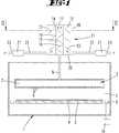
Die
Die Speisung des Gaseinlassorgans
Der Gasaustrittskanal
Die Gasmischvorrichtung besitzt ein kreiszylinderförmiges Gehäuse, wobei der Boden
Durch den Boden
Die Gasmischvorrichtung besitzt eine erste Mischkammer
Der vorgemischte Gasstrom wird im Bereich der Überströmungsbarriere
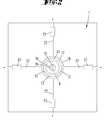
Bei dem in den
Die
Bei dem in den
Der U-Steg des U-förmigen Rohres
Eine parallel zu dem die erste Mischkammer
Im Ausführungsbeispiel sind die Gasumlenkelemente
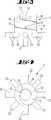
Die
Die innere, zweite Mischkammer
Die Flachteile sind an der Innenwandung des Innenrohres
Das in den
Auch hier bilden zwei koaxial zueinander angeordnete Rohre
In der zentralen zweiten Mischkammer
Bei allen zuvor beschriebenen Ausführungsbeispielen sind die Gasumlenkelemente
In die Einspeisekanäle
Die Gasmischung kann bei Atmosphärendruck stattfinden. Bevorzugt erfolgt die Gasmischung aber in einem Druckbereich zwischen 1 mbar und 500 mbar. Der Druckunterschied zwischen Quelle
Die vorstehenden Ausführungen dienen der Erläuterung der von der Anmeldung insgesamt erfassten Erfindungen, die den Stand der Technik zumindest durch die folgenden Merkmalskombinationen jeweils eigenständig weiterbilden, nämlich:
Eine Gasversorgungseinrichtung, die dadurch gekennzeichnet ist, dass die effektiven Weglängen der Einzelgasströme von den Gasquellen
A gas supply device, which is characterized in that the effective path lengths of the individual gas flows from the
Eine Gasversorgungseinrichtung, die dadurch gekennzeichnet ist, dass die Einlasskanäle
Eine Gasversorgungseinrichtung, die dadurch gekennzeichnet ist, dass die erste Mischkammer
Eine Gasversorgungseinrichtung, die dadurch gekennzeichnet ist, dass die ersten oder zweiten Gasumlenkelemente
Eine Gasversorgungseinrichtung, die dadurch gekennzeichnet ist, dass die erste und zweite Mischkammer
Eine Gasversorgungseinrichtung, die dadurch gekennzeichnet ist, dass die Durchmesser der ersten oder zweiten Mischkammer
Eine Gasversorgungseinrichtung, die dadurch gekennzeichnet ist, dass eine aus den beiden Mischkammern
Ein Verfahren, das dadurch gekennzeichnet ist, dass sich die effektiven Verweilzeiten der Gase auf dem Weg zwischen Gasquelle
Ein Verfahren, das dadurch gekennzeichnet ist, dass die Verweilzeit der Gase auf dem Weg zwischen Gasquelle
Ein Verfahren, das dadurch gekennzeichnet ist, dass die in der ersten Mischkammer
Ein Verfahren, das dadurch gekennzeichnet ist, dass die Gasströmungen in den Einlasskanälen
Alle offenbarten Merkmale sind (für sich, aber auch in Kombination untereinander) erfindungswesentlich. In die Offenbarung der Anmeldung wird hiermit auch der Offenbarungsinhalt der zugehörigen/beigefügten Prioritätsunterlagen (Abschrift der Voranmeldung) vollinhaltlich mit einbezogen, auch zu dem Zweck, Merkmale dieser Unterlagen in Ansprüche vorliegender Anmeldung mit aufzunehmen. Die Unteransprüche charakterisieren mit ihren Merkmalen eigenständige erfinderische Weiterbildungen des Standes der Technik, insbesondere um auf Basis dieser Ansprüche Teilanmeldungen vorzunehmen.All disclosed features are essential to the invention (individually, but also in combination with one another). In the disclosure of the application is hereby also the disclosure of the associated / attached priority documents (copy of the Advance notification), including for the purpose of including features of these documents in claims of the present application. The subclaims characterize with their features independent inventive developments of the prior art, in particular to make on the basis of these claims divisional applications.
BezugszeichenlisteLIST OF REFERENCE NUMBERS
- 11
- Reaktorgehäusereactor housing
- 22
- Prozesskammerprocess chamber
- 33
- Suszeptorsusceptor
- 44
- Substratsubstratum
- 55
- GaseinlassorganGas inlet element
- 66
- GasaustrittsöffnungGas outlet
- 77
- Gasverteilvolumengas distribution volume
- 88th
- GasaustrittskanalGas outlet channel
- 99
- Gasauslassorgangas outlet
- 1010
- Vakuumpumpevacuum pump
- 1111
- GasmischvorrichtungGas mixing device
- 1212
- erste Mischkammerfirst mixing chamber
- 1313
- erstes Gasumlenkelementfirst gas deflection element
- 13'13 '
- Hindernisobstacle
- 1414
- ÜberströmungsbarriereAbout flow barrier
- 1515
- Zweite MischkammerSecond mixing chamber
- 1616
- zweites Gasumlenkelementsecond gas deflection element
- 1717
- Deckeblanket
- 1818
- ZylindermantelwandCylinder jacket wall
- 1919
- Rohrpipe
- 2020
- Bodenground
- 2121
- Gasquellegas source
- 2222
- Einlasskanalinlet channel
- 22'22 '
- Einlasskanalinlet channel
- 2323
- Einspeisekanalfeed channel
- 2424
- GasumlenkelementGasumlenkelement
- 2525
- QuerkanalQuerkanal
ZITATE ENTHALTEN IN DER BESCHREIBUNG QUOTES INCLUDE IN THE DESCRIPTION
Diese Liste der vom Anmelder aufgeführten Dokumente wurde automatisiert erzeugt und ist ausschließlich zur besseren Information des Lesers aufgenommen. Die Liste ist nicht Bestandteil der deutschen Patent- bzw. Gebrauchsmusteranmeldung. Das DPMA übernimmt keinerlei Haftung für etwaige Fehler oder Auslassungen.This list of the documents listed by the applicant has been generated automatically and is included solely for the better information of the reader. The list is not part of the German patent or utility model application. The DPMA assumes no liability for any errors or omissions.
Zitierte PatentliteraturCited patent literature
- US 2009/0120364 A1[0003]US 2009/0120364 A1[0003]
- US 7540305 B2[0005]US 7540305 B2[0005]
- DE 102005003984 A1[0006]DE 102005003984 A1[0006]
- US 2003/0019428 A1[0006]US 2003/0019428 A1[0006]
- DE 102013113817[0007]DE 102013113817[0007]
- EP 1252363 B1[0008]EP 1252363 B1[0008]
Claims (12)
Translated fromGermanPriority Applications (6)
| Application Number | Priority Date | Filing Date | Title |
|---|---|---|---|
| DE102014106523.9ADE102014106523A1 (en) | 2014-05-09 | 2014-05-09 | Apparatus and method for supplying a CVD or PVD coating device with a process gas mixture |
| JP2016565413AJP6796491B2 (en) | 2014-05-09 | 2015-05-07 | Equipment and methods for supplying process gas mixtures to CVD or PVD coating equipment |
| CN201580027176.9ACN106457168A (en) | 2014-05-09 | 2015-05-07 | Device and method for providing a process gas mixture to a cvd or pvd coating device |
| KR1020167034147AKR102413577B1 (en) | 2014-05-09 | 2015-05-07 | Device and method for providing a process gas mixture to a cvd or pvd coating device |
| PCT/EP2015/060017WO2015169882A1 (en) | 2014-05-09 | 2015-05-07 | Device and method for providing a process gas mixture to a cvd or pvd coating device |
| TW104114708ATWI694168B (en) | 2014-05-09 | 2015-05-08 | Device and method for supplying a cvd or pvd coating device with a process gas mixture |
Applications Claiming Priority (1)
| Application Number | Priority Date | Filing Date | Title |
|---|---|---|---|
| DE102014106523.9ADE102014106523A1 (en) | 2014-05-09 | 2014-05-09 | Apparatus and method for supplying a CVD or PVD coating device with a process gas mixture |
Publications (1)
| Publication Number | Publication Date |
|---|---|
| DE102014106523A1true DE102014106523A1 (en) | 2015-11-12 |
Family
ID=53199950
Family Applications (1)
| Application Number | Title | Priority Date | Filing Date |
|---|---|---|---|
| DE102014106523.9APendingDE102014106523A1 (en) | 2014-05-09 | 2014-05-09 | Apparatus and method for supplying a CVD or PVD coating device with a process gas mixture |
Country Status (6)
| Country | Link |
|---|---|
| JP (1) | JP6796491B2 (en) |
| KR (1) | KR102413577B1 (en) |
| CN (1) | CN106457168A (en) |
| DE (1) | DE102014106523A1 (en) |
| TW (1) | TWI694168B (en) |
| WO (1) | WO2015169882A1 (en) |
Cited By (6)
| Publication number | Priority date | Publication date | Assignee | Title |
|---|---|---|---|---|
| CN111804453A (en)* | 2020-07-21 | 2020-10-23 | 黄安淇 | Spraying mechanism in surface spraying machine for aluminum alloy section |
| DE102019129176A1 (en)* | 2019-10-29 | 2021-04-29 | Apeva Se | Method and device for depositing organic layers |
| DE102020112568A1 (en) | 2020-02-14 | 2021-08-19 | AIXTRON Ltd. | Gas inlet element for a CVD reactor |
| CN113430502A (en)* | 2021-06-18 | 2021-09-24 | 北京北方华创微电子装备有限公司 | Semiconductor process equipment and mixed air inlet device thereof |
| CN113813858A (en)* | 2021-11-10 | 2021-12-21 | 西安国际医学中心有限公司 | Compounding device of painful plaster preparation of treatment cancer |
| CN114768578A (en)* | 2022-05-20 | 2022-07-22 | 北京北方华创微电子装备有限公司 | Gas mixing device and semiconductor process equipment |
Families Citing this family (14)
| Publication number | Priority date | Publication date | Assignee | Title |
|---|---|---|---|---|
| JP2020020532A (en)* | 2018-08-01 | 2020-02-06 | 三菱電機株式会社 | Temperature equalization device, structure and parabolic antenna device |
| CN110237734A (en)* | 2019-06-10 | 2019-09-17 | 中国石油大学(北京) | Gas mixer and waste gas treatment device |
| US11772058B2 (en) | 2019-10-18 | 2023-10-03 | Taiwan Semiconductor Manufacturing Company Limited | Gas mixing system for semiconductor fabrication |
| CN110773061B (en)* | 2019-11-05 | 2021-09-21 | 浙江工业职业技术学院 | Stirring device |
| CN110917914B (en)* | 2019-12-19 | 2022-09-16 | 北京北方华创微电子装备有限公司 | Gas mixing device and semiconductor processing equipment |
| CN111744340A (en)* | 2020-07-02 | 2020-10-09 | 天津市英格环保科技有限公司 | Method for desulfurization and denitrification in low-temperature environment |
| KR102635385B1 (en)* | 2020-11-23 | 2024-02-14 | 세메스 주식회사 | Apparatuse for treating substrate |
| CN112973483A (en)* | 2021-03-29 | 2021-06-18 | 深圳市科曼医疗设备有限公司 | Gas mixing device |
| CN116949392A (en)* | 2022-04-18 | 2023-10-27 | 中微半导体设备(上海)股份有限公司 | A gas mixer, gas spray device and method of use |
| KR102831131B1 (en)* | 2022-05-18 | 2025-07-04 | 한화모멘텀 주식회사 | Substrate processing apparatus |
| KR102828639B1 (en)* | 2022-10-31 | 2025-07-02 | 주식회사 에스지에스코리아 | Gas injector and substrate treating apparatus using same |
| WO2025029735A1 (en)* | 2023-08-01 | 2025-02-06 | Lam Research Corporation | Processing tool showerhead with integrated static mixer |
| US20250277307A1 (en)* | 2024-03-01 | 2025-09-04 | Applied Materials, Inc. | 3d printed integrated gas mixer |
| CN119132927B (en)* | 2024-11-11 | 2025-03-14 | 无锡尚积半导体科技有限公司 | Device and method for pre-cleaning wafer surface |
Citations (10)
| Publication number | Priority date | Publication date | Assignee | Title |
|---|---|---|---|---|
| US6068703A (en)* | 1997-07-11 | 2000-05-30 | Applied Materials, Inc. | Gas mixing apparatus and method |
| US6495233B1 (en)* | 1999-07-09 | 2002-12-17 | Applied Materials, Inc. | Apparatus for distributing gases in a chemical vapor deposition system |
| US20030019428A1 (en) | 2001-04-28 | 2003-01-30 | Applied Materials, Inc. | Chemical vapor deposition chamber |
| EP1252363B1 (en) | 2000-02-04 | 2003-09-10 | Aixtron AG | Device and method for depositing one or more layers onto a substrate |
| US6758591B1 (en)* | 2002-03-22 | 2004-07-06 | Novellus Systems, Inc. | Mixing of materials in an integrated circuit manufacturing equipment |
| DE102005003984A1 (en) | 2005-01-28 | 2006-08-03 | Aixtron Ag | Gas inlet element for a chemical vapor deposition (CVD) reactor useful in CVD reactors with base outlets for introduction of process gas via edge side access holes and mixing chamber upstream of access holes for homogenizing gas composition |
| US20090120364A1 (en) | 2007-11-09 | 2009-05-14 | Applied Materials, Inc. | Gas mixing swirl insert assembly |
| US7540305B2 (en) | 2003-02-14 | 2009-06-02 | Tokyo Electron Limited | Chemical processing system and method |
| EP1452626B1 (en)* | 2001-12-03 | 2010-11-10 | Ulvac, Inc. | Mixer, and device and method for manufacturing thin film |
| DE102013113817A1 (en) | 2012-12-14 | 2014-06-18 | Aixtron Se | Gas mixing device |
Family Cites Families (22)
| Publication number | Priority date | Publication date | Assignee | Title |
|---|---|---|---|---|
| US4408893A (en)* | 1982-04-28 | 1983-10-11 | Luwa A.G. | Motionless mixing device |
| JPS5949829A (en)* | 1982-09-14 | 1984-03-22 | Matsushita Electric Ind Co Ltd | Fluid mixer and thin film device using said mixer |
| US4850705A (en)* | 1987-11-18 | 1989-07-25 | Horner Terry A | Motionless mixers and baffles |
| JP3609329B2 (en)* | 1992-09-07 | 2005-01-12 | 三菱電機株式会社 | Nitride film forming method |
| CN1171485A (en) | 1996-03-18 | 1998-01-28 | 郑宜智 | Gas swirling device for internal combusion engine and its manufacturing method |
| JP3360539B2 (en)* | 1996-07-12 | 2002-12-24 | 信越半導体株式会社 | Gas supply device and equipment for vapor phase growth |
| JPH11293465A (en)* | 1998-04-15 | 1999-10-26 | Ebara Corp | Cvd device |
| US6601986B2 (en)* | 2001-08-29 | 2003-08-05 | Taiwan Semiconductor Manufacturing Co., Ltd | Fluid mixing apparatus |
| JP2003142473A (en)* | 2001-10-31 | 2003-05-16 | Tokyo Electron Ltd | Gas supplying apparatus and method therefor, and film forming apparatus and method therefor |
| WO2006020424A2 (en)* | 2004-08-02 | 2006-02-23 | Veeco Instruments Inc. | Multi-gas distribution injector for chemical vapor deposition reactors |
| GB0603917D0 (en)* | 2006-02-28 | 2006-04-05 | Stein Peter | Gas retention vessel |
| CN201086001Y (en)* | 2007-08-22 | 2008-07-16 | 张国栋 | Static mixer and spiral mixing element thereof |
| US8334015B2 (en)* | 2007-09-05 | 2012-12-18 | Intermolecular, Inc. | Vapor based combinatorial processing |
| CN101371975B (en)* | 2008-09-26 | 2010-06-09 | 沈阳化工学院 | Multi-channel spiral static mixer |
| SG183536A1 (en) | 2010-03-12 | 2012-09-27 | Applied Materials Inc | Atomic layer deposition chamber with multi inject |
| CN202052481U (en)* | 2010-04-30 | 2011-11-30 | 中国人民解放军总装备部后勤部防疫大队 | Hydrazine propellant standard gas generator |
| JP2012030207A (en)* | 2010-08-03 | 2012-02-16 | Soken Kogyo Kk | Fluid mixer, fluid mixing and transporting channel, and fluid mixing method |
| KR101829669B1 (en)* | 2011-01-04 | 2018-02-19 | 주식회사 원익아이피에스 | Method of depositing thin film and Apparatus for depositing thin film |
| US8485230B2 (en)* | 2011-09-08 | 2013-07-16 | Laor Consulting Llc | Gas delivery system |
| US10232324B2 (en)* | 2012-07-12 | 2019-03-19 | Applied Materials, Inc. | Gas mixing apparatus |
| CN102974257B (en)* | 2012-12-03 | 2014-09-17 | 山西新华化工有限责任公司 | Dynamic activity detection mixer |
| CN203484064U (en)* | 2013-08-14 | 2014-03-19 | 新密港华燃气有限公司 | Device for evenly mixing four gases |
- 2014
- 2014-05-09DEDE102014106523.9Apatent/DE102014106523A1/enactivePending
- 2015
- 2015-05-07WOPCT/EP2015/060017patent/WO2015169882A1/enactiveApplication Filing
- 2015-05-07CNCN201580027176.9Apatent/CN106457168A/enactivePending
- 2015-05-07KRKR1020167034147Apatent/KR102413577B1/enactiveActive
- 2015-05-07JPJP2016565413Apatent/JP6796491B2/enactiveActive
- 2015-05-08TWTW104114708Apatent/TWI694168B/enactive
Patent Citations (10)
| Publication number | Priority date | Publication date | Assignee | Title |
|---|---|---|---|---|
| US6068703A (en)* | 1997-07-11 | 2000-05-30 | Applied Materials, Inc. | Gas mixing apparatus and method |
| US6495233B1 (en)* | 1999-07-09 | 2002-12-17 | Applied Materials, Inc. | Apparatus for distributing gases in a chemical vapor deposition system |
| EP1252363B1 (en) | 2000-02-04 | 2003-09-10 | Aixtron AG | Device and method for depositing one or more layers onto a substrate |
| US20030019428A1 (en) | 2001-04-28 | 2003-01-30 | Applied Materials, Inc. | Chemical vapor deposition chamber |
| EP1452626B1 (en)* | 2001-12-03 | 2010-11-10 | Ulvac, Inc. | Mixer, and device and method for manufacturing thin film |
| US6758591B1 (en)* | 2002-03-22 | 2004-07-06 | Novellus Systems, Inc. | Mixing of materials in an integrated circuit manufacturing equipment |
| US7540305B2 (en) | 2003-02-14 | 2009-06-02 | Tokyo Electron Limited | Chemical processing system and method |
| DE102005003984A1 (en) | 2005-01-28 | 2006-08-03 | Aixtron Ag | Gas inlet element for a chemical vapor deposition (CVD) reactor useful in CVD reactors with base outlets for introduction of process gas via edge side access holes and mixing chamber upstream of access holes for homogenizing gas composition |
| US20090120364A1 (en) | 2007-11-09 | 2009-05-14 | Applied Materials, Inc. | Gas mixing swirl insert assembly |
| DE102013113817A1 (en) | 2012-12-14 | 2014-06-18 | Aixtron Se | Gas mixing device |
Cited By (10)
| Publication number | Priority date | Publication date | Assignee | Title |
|---|---|---|---|---|
| DE102019129176A1 (en)* | 2019-10-29 | 2021-04-29 | Apeva Se | Method and device for depositing organic layers |
| WO2021083956A1 (en) | 2019-10-29 | 2021-05-06 | Apeva Se | Method and apparatus for depositing organic layers |
| DE102020112568A1 (en) | 2020-02-14 | 2021-08-19 | AIXTRON Ltd. | Gas inlet element for a CVD reactor |
| CN111804453A (en)* | 2020-07-21 | 2020-10-23 | 黄安淇 | Spraying mechanism in surface spraying machine for aluminum alloy section |
| CN113430502A (en)* | 2021-06-18 | 2021-09-24 | 北京北方华创微电子装备有限公司 | Semiconductor process equipment and mixed air inlet device thereof |
| US12264393B2 (en) | 2021-06-18 | 2025-04-01 | Beijing Naura Microelectronics Equipment Co., Ltd. | Semiconductor processing apparatus and mixing inlet device |
| CN113813858A (en)* | 2021-11-10 | 2021-12-21 | 西安国际医学中心有限公司 | Compounding device of painful plaster preparation of treatment cancer |
| CN113813858B (en)* | 2021-11-10 | 2023-01-31 | 西安国际医学中心有限公司 | Compounding device of painful plaster preparation of treatment cancer |
| CN114768578A (en)* | 2022-05-20 | 2022-07-22 | 北京北方华创微电子装备有限公司 | Gas mixing device and semiconductor process equipment |
| CN114768578B (en)* | 2022-05-20 | 2023-08-18 | 北京北方华创微电子装备有限公司 | Gas mixing device and semiconductor process equipment |
Also Published As
| Publication number | Publication date |
|---|---|
| TWI694168B (en) | 2020-05-21 |
| TW201602398A (en) | 2016-01-16 |
| JP2017522447A (en) | 2017-08-10 |
| WO2015169882A1 (en) | 2015-11-12 |
| JP6796491B2 (en) | 2020-12-09 |
| KR102413577B1 (en) | 2022-06-24 |
| KR20170003965A (en) | 2017-01-10 |
| CN106457168A (en) | 2017-02-22 |
Similar Documents
| Publication | Publication Date | Title |
|---|---|---|
| DE102014106523A1 (en) | Apparatus and method for supplying a CVD or PVD coating device with a process gas mixture | |
| EP1967806B1 (en) | Device for heat exchange and mixing treatment of fluid mediums | |
| DE4120176C1 (en) | ||
| DE1519711C3 (en) | Feeding a vapor-liquid mixture into mass transfer columns | |
| DE102013113817A1 (en) | Gas mixing device | |
| EP0317706B1 (en) | Flue gas channel for treating a flue gas | |
| DE102014201908A1 (en) | Method for guiding a fluid flow, flow apparatus and its use | |
| EP1349968B1 (en) | Liquid distribution unit for multiple fluids | |
| EP2963147B1 (en) | Device for generating a vapour from a solid or liquid starting material for a cvd or pvd device | |
| EP3246095A1 (en) | Nozzle for spraying fluid | |
| WO2020053408A1 (en) | Outlet for water fittings | |
| DE102005023956A1 (en) | Compact total evaporator | |
| DE102017001025A1 (en) | Nozzle lance, incinerator and exhaust treatment method | |
| WO2011098420A1 (en) | Gas inlet member with baffle plate arrangement | |
| DE102015102312A1 (en) | Tube bundle heat exchanger with sequentially arranged tube bundle components | |
| EP3338882A1 (en) | Mixing element with high strength and mixing effect | |
| DE102015113432A1 (en) | Flow guide in a channel | |
| WO2019002253A1 (en) | DISTRIBUTOR FOR A FLUID | |
| DE3004864C2 (en) | Device for spraying a propellant and cooling agent mixture onto cast strands | |
| DE102004040082A1 (en) | Water outlet mouthpiece for the water outlet of a faucet | |
| CH630948A5 (en) | SOOT PRODUCTION PLANT. | |
| WO2017121704A1 (en) | Device for providing a process gas in a coating device | |
| DE3920123C1 (en) | ||
| AT526379B1 (en) | Flow arrangement for supplying a media flow to inlet openings of fuel cell stacks | |
| EP0504550B1 (en) | Mixing chamber |
Legal Events
| Date | Code | Title | Description |
|---|---|---|---|
| R163 | Identified publications notified | ||
| R012 | Request for examination validly filed |