DE102014102308A1 - Lifting column for a medical facility - Google Patents
Lifting column for a medical facilityDownload PDFInfo
- Publication number
- DE102014102308A1 DE102014102308A1DE102014102308.0ADE102014102308ADE102014102308A1DE 102014102308 A1DE102014102308 A1DE 102014102308A1DE 102014102308 ADE102014102308 ADE 102014102308ADE 102014102308 A1DE102014102308 A1DE 102014102308A1
- Authority
- DE
- Germany
- Prior art keywords
- sliding
- column
- pillar
- elements
- lifting column
- Prior art date
- Legal status (The legal status is an assumption and is not a legal conclusion. Google has not performed a legal analysis and makes no representation as to the accuracy of the status listed.)
- Ceased
Links
Images

Classifications
- A—HUMAN NECESSITIES
- A61—MEDICAL OR VETERINARY SCIENCE; HYGIENE
- A61G—TRANSPORT, PERSONAL CONVEYANCES, OR ACCOMMODATION SPECIALLY ADAPTED FOR PATIENTS OR DISABLED PERSONS; OPERATING TABLES OR CHAIRS; CHAIRS FOR DENTISTRY; FUNERAL DEVICES
- A61G13/00—Operating tables; Auxiliary appliances therefor
- A61G13/02—Adjustable operating tables; Controls therefor
- A61G13/06—Adjustable operating tables; Controls therefor raising or lowering of the whole table surface
- A—HUMAN NECESSITIES
- A47—FURNITURE; DOMESTIC ARTICLES OR APPLIANCES; COFFEE MILLS; SPICE MILLS; SUCTION CLEANERS IN GENERAL
- A47B—TABLES; DESKS; OFFICE FURNITURE; CABINETS; DRAWERS; GENERAL DETAILS OF FURNITURE
- A47B9/00—Tables with tops of variable height
- A47B9/20—Telescopic guides
- A—HUMAN NECESSITIES
- A61—MEDICAL OR VETERINARY SCIENCE; HYGIENE
- A61G—TRANSPORT, PERSONAL CONVEYANCES, OR ACCOMMODATION SPECIALLY ADAPTED FOR PATIENTS OR DISABLED PERSONS; OPERATING TABLES OR CHAIRS; CHAIRS FOR DENTISTRY; FUNERAL DEVICES
- A61G13/00—Operating tables; Auxiliary appliances therefor
- A61G13/10—Parts, details or accessories
- F—MECHANICAL ENGINEERING; LIGHTING; HEATING; WEAPONS; BLASTING
- F16—ENGINEERING ELEMENTS AND UNITS; GENERAL MEASURES FOR PRODUCING AND MAINTAINING EFFECTIVE FUNCTIONING OF MACHINES OR INSTALLATIONS; THERMAL INSULATION IN GENERAL
- F16M—FRAMES, CASINGS OR BEDS OF ENGINES, MACHINES OR APPARATUS, NOT SPECIFIC TO ENGINES, MACHINES OR APPARATUS PROVIDED FOR ELSEWHERE; STANDS; SUPPORTS
- F16M11/00—Stands or trestles as supports for apparatus or articles placed thereon ; Stands for scientific apparatus such as gravitational force meters
- F16M11/20—Undercarriages with or without wheels
- F16M11/24—Undercarriages with or without wheels changeable in height or length of legs, also for transport only, e.g. by means of tubes screwed into each other
- F16M11/26—Undercarriages with or without wheels changeable in height or length of legs, also for transport only, e.g. by means of tubes screwed into each other by telescoping, with or without folding
- A—HUMAN NECESSITIES
- A47—FURNITURE; DOMESTIC ARTICLES OR APPLIANCES; COFFEE MILLS; SPICE MILLS; SUCTION CLEANERS IN GENERAL
- A47B—TABLES; DESKS; OFFICE FURNITURE; CABINETS; DRAWERS; GENERAL DETAILS OF FURNITURE
- A47B2200/00—General construction of tables or desks
- A47B2200/0035—Tables or desks with features relating to adjustability or folding
- A47B2200/005—Leg adjustment
- A47B2200/0051—Telescopic
- A47B2200/0054—Telescopic with three telescopic parts
- B—PERFORMING OPERATIONS; TRANSPORTING
- B25—HAND TOOLS; PORTABLE POWER-DRIVEN TOOLS; MANIPULATORS
- B25B—TOOLS OR BENCH DEVICES NOT OTHERWISE PROVIDED FOR, FOR FASTENING, CONNECTING, DISENGAGING OR HOLDING
- B25B27/00—Hand tools, specially adapted for fitting together or separating parts or objects whether or not involving some deformation, not otherwise provided for
- B25B27/02—Hand tools, specially adapted for fitting together or separating parts or objects whether or not involving some deformation, not otherwise provided for for connecting objects by press fit or detaching same
- B25B27/06—Hand tools, specially adapted for fitting together or separating parts or objects whether or not involving some deformation, not otherwise provided for for connecting objects by press fit or detaching same inserting or withdrawing sleeves or bearing races
- B25B27/062—Hand tools, specially adapted for fitting together or separating parts or objects whether or not involving some deformation, not otherwise provided for for connecting objects by press fit or detaching same inserting or withdrawing sleeves or bearing races using screws
Landscapes
- Health & Medical Sciences (AREA)
- Engineering & Computer Science (AREA)
- Biomedical Technology (AREA)
- Life Sciences & Earth Sciences (AREA)
- Animal Behavior & Ethology (AREA)
- General Health & Medical Sciences (AREA)
- Public Health (AREA)
- Veterinary Medicine (AREA)
- General Engineering & Computer Science (AREA)
- Mechanical Engineering (AREA)
- Accommodation For Nursing Or Treatment Tables (AREA)
- Steps, Ramps, And Handrails (AREA)
- Invalid Beds And Related Equipment (AREA)
- Infusion, Injection, And Reservoir Apparatuses (AREA)
- Refuge Islands, Traffic Blockers, Or Guard Fence (AREA)
- Sealing Devices (AREA)
Abstract
Translated fromGermanDescription
Translated fromGermanDie Erfindung betrifft eine Hubsäule für eine medizinische Einrichtung, mit mindestens zwei Säulenelementen, die in ihrer übereinstimmenden Längsrichtung relativ zueinander bewegbar sind, und mit mindestens einem Gleitelement, das an einer Innenfläche eines ersten der beiden Säulenelemente befestigt ist. Das Gleitelement hat eine Gleitfläche, die an einer der Innenfläche des ersten Säulenelements zugewandten Außenfläche eines zweiten der beiden Säulenelemente gleitend gelagert ist. Weiterhin betrifft die Erfindung ein Verfahren zum Zusammensetzen einer solchen Hubsäule.The invention relates to a lifting column for a medical device, having at least two column elements which are movable in their coincident longitudinal direction relative to each other, and having at least one sliding element which is fixed to an inner surface of a first of the two column elements. The sliding member has a sliding surface which is slidably supported on an outer surface of a second one of the two pillar members facing the inner surface of the first pillar member. Furthermore, the invention relates to a method for assembling such a lifting column.
Hubsäulen für medizinische Einrichtungen finden sich beispielsweise in Operationstischen, Transportern für Lagerflächen oder Zureichewägen. Die Anforderungen an solche Hubsäulen werden im Folgenden am Beispiel eines Operationstischs erläutert.Lifting columns for medical facilities can be found, for example, in operating tables, vans for storage areas or full-weight vehicles. The requirements for such lifting columns are explained below using the example of an operating table.
Vor und während einer Operation eines auf einer Patientenlagerfläche eines Operationstischs gelagerten Patienten wird die Patientenlagerfläche in eine Position gebracht, die einen Eingriff am Patienten ermöglicht. Dabei kann es erforderlich sein, die Patientenlagerfläche um eine horizontale Achse in einem vergleichsweise großen Winkelbereich zu verschwenken. Auch die Höhe der Patientenlagerfläche des Operationstisches sollte in einem möglichst großen Bereich einstellbar sein. Idealerweise lässt sich der Operationstisch auch so einstellen, dass die Patientenlagerfläche in sehr geringen Höhen angeordnet ist, was eine platzsparende Bauweise der Operationstischsäule voraussetzt.Before and during an operation of a patient supported on a patient support surface of an operating table, the patient support surface is brought into a position that allows an intervention on the patient. It may be necessary to pivot the patient support surface about a horizontal axis in a comparatively large angular range. The height of the patient support surface of the operating table should be adjustable in the largest possible range. Ideally, the operating table can also be adjusted so that the patient support surface is arranged at very low levels, which requires a space-saving design of the operating table column.
Auch während der Operation kann es erforderlich sein, die Lage, insbesondere die Höhe, eines Patienten zu verändern. Die der Lageveränderung dienenden Bauteile müssen deshalb zuverlässig funktionieren. Insbesondere müssen diese Bauteile so präzise geführt sein, dass eine Höhenverstellung ohne Verkanten der Bauteile möglich ist. Zudem neigen die beweglichen Bauteile des Operationstischs zum Verschleiß und müssen deshalb besonders stabil und langlebig ausgeführt sein.Also during the surgery, it may be necessary to change the position, in particular the height, of a patient. The position change serving components must therefore work reliably. In particular, these components must be performed so precisely that a height adjustment without tilting of the components is possible. In addition, the movable components of the operating table tend to wear and must therefore be made particularly stable and durable.
Typischerweise werden die zur Höhenverstellung dienenden Bauteile als Hubsäulen ausgeführt, bei denen mehrere Säulenelemente entlang ihrer gemeinsamen Längsachse ineinander verschoben werden. Da die Innenflächen der Säulenelemente der Bearbeitung schlecht zugänglich sind, sind diese oft weniger präzise, insbesondere weniger glatt ausgeführt. Deshalb eignen sie sich nicht so gut als Gleitflächen wie die leichter bearbeitbaren Außenflächen der Säulenelemente.Typically, the height adjustment components are designed as lifting columns, in which a plurality of column elements are shifted along their common longitudinal axis. Since the inner surfaces of the column elements of the machining are difficult to access, they are often less precise, in particular executed less smooth. Therefore, they are not as well suited as sliding surfaces as the more easily editable outer surfaces of the column elements.
Aus der Druckschrift
Es ist Aufgabe der Erfindung, eine Hubsäule für einen Operationstisch anzugeben, die einfach zu montieren ist und im Wesentlichen keine Nachjustage der Gleitelemente erfordert.It is an object of the invention to provide a lifting column for an operating table, which is easy to assemble and requires essentially no readjustment of the sliding elements.
Diese Aufgabe wird durch eine Hubsäule mit den Merkmalen des Anspruchs 1 sowie durch ein Verfahren mit den Merkmalen des nebengeordneten Anspruchs 13 gelöst. Vorteilhafte Weiterbildungen der Erfindung sind in den abhängigen Ansprüchen angegeben.This object is achieved by a lifting column with the features of claim 1 and by a method having the features of the independent claim 13. Advantageous developments of the invention are specified in the dependent claims.
Die erfindungsgemäße Hubsäule hat mindestens zwei Säulenelemente, die in ihrer übereinstimmenden Längsrichtung relativ zueinander bewegbar sind, und mindestens ein Gleitelement, das an einer Innenfläche eines ersten der beiden Säulenelemente befestigt ist. Das Gleitelement hat eine Gleitfläche, die an einer der Innenfläche des ersten Säulenelements zugewandten Außenfläche eines zweiten der beiden Säulenelemente gleitend gelagert ist. In einem Raum zwischen der Gleitfläche des Gleitelements und der Innenfläche des ersten Säulenelements ist eine Vergussmasse ausgehärtet.The lifting column according to the invention has at least two column elements, which are movable in their coincident longitudinal direction relative to each other, and at least one sliding element, which is fixed to an inner surface of a first of the two column elements. The sliding member has a sliding surface which is slidably supported on an outer surface of a second one of the two pillar members facing the inner surface of the first pillar member. In a space between the sliding surface of the sliding member and the inner surface of the first pillar member, a potting compound is cured.
Durch die vorstehend angegebene Hubsäule wird erreicht, dass das Gleitelement gleichmäßig von der Vergussmasse an die Außenfläche des zweiten Säulenelements gedrückt wird. Insbesondere sind herstellungsbedingte Unebenheiten der Innenfläche des ersten Säulenelements einfacher ausgleichbar, als dies durch ein vorgefertigtes festes Bauteil möglich wäre. Die Vergussmasse ist einfach einzufüllen und muss nicht wie ein festes Bauteil aufwendig am ersten Säulenelement befestigt werden.By the above-mentioned lifting column is achieved that the sliding member is pressed uniformly from the potting compound to the outer surface of the second pillar member. In particular, manufacturing-related unevenness of the inner surface of the first pillar element are easier to compensate than would be possible by a prefabricated solid component. The potting compound is easy to fill and does not need to be fixed like a solid component consuming the first pillar element.
Das erste und das zweite Säulenelement haben einen geschlossenen Querschnitt. Insbesondere ist das erste Säulenelement ein länglicher Hohlkörper. Das zweite Säulenelement ist ein länglicher Körper, der vorzugsweise wie das erste Säulenelement innen hohl ist. Als Vergussmasse kann ein Gießharz verwendet werden, das druckstabil und schwindungsarm ist. Dadurch wird beim Aushärten ein Volumenschwund weitestgehend vermieden. Die Druckstabilität der Vergussmasse erlaubt es, dass letztere die Kräfte zwischen der Innenfläche des ersten Säulenelements und der Außenfläche des zweiten Säulenelements gut überträgt. Außerdem werden hohe mechanische Beanspruchungen des Gleitelements vermieden.The first and second column members have a closed cross-section. In particular, the first column element is an elongated hollow body. The second pillar member is an elongated body which is preferably hollow like the first pillar member. As potting compound can Cast resin can be used, which is pressure stable and low shrinkage. As a result, a volume shrinkage is largely avoided during curing. The pressure stability of the potting compound allows the latter to transmit well the forces between the inner surface of the first pillar member and the outer surface of the second pillar member. In addition, high mechanical stresses of the sliding element can be avoided.
Eine vorteilhafte Weiterbildung der Erfindung besteht darin, dass das erste Säulenelement mindestens ein Durchgangsloch zum Einfüllen der auszuhärtenden Vergussmasse hat. Dadurch kann die Vergussmasse leicht von außen in den Raum zwischen der Gleitfläche und der Innenfläche des ersten Säulenelements eingefüllt werden. Vorzugsweise ist das Durchgangsloch eine Bohrung in der Wand des ersten Säulenelements.An advantageous development of the invention consists in that the first column element has at least one through hole for filling the curing compound to be cured. Thereby, the potting compound can be easily filled from the outside into the space between the sliding surface and the inner surface of the first column member. Preferably, the through hole is a bore in the wall of the first pillar member.
Vorzugsweise hat das Gleitelement einen Tragekörper und eine Gleitschicht mit einer die Gleitfläche bildenden Oberfläche. Die Gleitschicht kontaktiert in diesem Fall über ihre Gleitfläche die Außenwand des zweiten Säulenelements, während der Tragekörper die Vergussmasse kontaktiert. Durch die schichtweise Ausführung des Gleitelements können optimale Gleiteigenschaften mit der nötigen Stabilität kombiniert werden. Die Gleitschicht ist dabei vorzugsweise aus einem Verbundwerkstoff und der Tragekörper vorzugsweise aus Metall gefertigt.Preferably, the sliding element has a support body and a sliding layer with a surface forming the sliding surface. In this case, the sliding layer contacts the outer wall of the second pillar element via its sliding surface, while the support body contacts the casting compound. Due to the layered design of the sliding element optimal sliding properties can be combined with the necessary stability. The sliding layer is preferably made of a composite material and the support body is preferably made of metal.
Ferner ist es vorteilhaft, wenn der Tragekörper rechteckig geformt ist und die Gleitschicht zumindest auf einem Teil der der Außenfläche des zweiten Säulenelements zugewandten Oberfläche des Tragekörpers angeordnet ist. Durch seine rechteckige Form ist das Gleitelement in eine Hubsäule, die typischerweise einen rechteckigen Querschnitt hat, gut einpassbar und stabilisiert die beiden Säulenelemente optimal gegen ein Verkippen um eine Achse, die senkrecht zur gemeinsamen Längsachse der Säulenelemente liegt.Further, it is advantageous if the support body is rectangular in shape and the sliding layer is arranged at least on a part of the outer surface of the second pillar member facing surface of the support body. By its rectangular shape, the slider is in a lifting column, which typically has a rectangular cross-section, well fitted and stabilizes the two column elements optimally against tilting about an axis which is perpendicular to the common longitudinal axis of the column elements.
Bei einer weiteren vorteilhaften Weiterbildung der Erfindung haftet das Gleitelement durch die ausgehärtete Vergussmasse an der Innenfläche des ersten Säulenelements. Dadurch erübrigt sich eine weitere mechanische Verbindung des Tragekörpers mit dem ersten Säulenelement. Das Gleitelement haftet dabei insbesondere so an der Innenfläche des ersten Säulenelements, dass es translationsfest mit dieser Innenfläche verbunden ist.In a further advantageous development of the invention, the sliding element adheres to the inner surface of the first column element by the hardened potting compound. As a result, a further mechanical connection of the support body with the first pillar element is unnecessary. In this case, the sliding element adheres in particular to the inner surface of the first column element in such a way that it is connected to this inner surface in a manner resistant to translation.
Ferner ist es vorteilhaft, wenn das Gleitelement mindestens ein Rastelement hat, das in einer Aussparung des ersten Säulenelements aufgenommen ist und über das das Gleitelement in Längsrichtung des ersten Säulenelements fixiert ist. Dadurch vereinfacht sich das Einbringen des Gleitelements beim Zusammensetzen der Hubsäule.Furthermore, it is advantageous if the sliding element has at least one latching element which is received in a recess of the first column element and via which the sliding element is fixed in the longitudinal direction of the first column element. This simplifies the introduction of the sliding element when assembling the lifting column.
Vorzugsweise ist eine Dichtung zwischen dem Gleitelement und der Innenfläche des ersten Säulenelements um den die Vergussmasse aufnehmenden Raum umlaufend angeordnet. Dadurch wird verhindert, dass die Vergussmasse beim Einfüllen aus dem Raum zwischen der Gleitfläche und der Innenfläche des ersten Säulenelements herausfließt. Außerdem kann dadurch der Raum möglichst vollständig mit Vergussmasse ausgefüllt werden, so dass die Druckstabilität und die Haftung maximiert werden.Preferably, a seal between the sliding member and the inner surface of the first pillar member around the potting compound receiving space is arranged circumferentially. This prevents the potting compound from flowing out of the space between the sliding surface and the inner surface of the first pillar member during filling. In addition, the space can be filled as completely as possible with casting compound, so that the pressure stability and adhesion are maximized.
In einer vorteilhaften Ausgestaltung ist die Dichtung senkrecht zur Längsachse des ersten Säulenelements elastisch verformbar. In Folge der Elastizität der Dichtung wird das Gleitelement gegen die Außenfläche des zweiten Säulenelements gedrückt. Damit sind optimale Gleiteigenschaften sichergestellt.In an advantageous embodiment, the seal is elastically deformable perpendicular to the longitudinal axis of the first column member. Due to the elasticity of the seal, the sliding member is pressed against the outer surface of the second pillar member. This ensures optimum gliding properties.
Haben das erste und das zweite Säulenelement jeweils einen rechteckigen Querschnitt, so besteht eine weitere vorteilhafte Weiterbildung darin, dass das mindestens eine Gleitelement vier Gleitelemente umfasst, und dass an jeder der vier Innenflächen des ersten Säulenelements jeweils eines der vier Gleitelemente befestigt ist. Dadurch ist auf einfache Weise eine gleichartige Gleitlagerung zwischen den miteinander in Anlage befindlichen Flächen der beiden Säulenelemente realisierbar.If the first and the second pillar element each have a rectangular cross-section, a further advantageous development is that the at least one sliding element comprises four sliding elements, and in each case one of the four sliding elements is fastened to each of the four inner surfaces of the first pillar element. As a result, a similar sliding bearing between the abutting surfaces of the two column elements can be realized in a simple manner.
Ferner ist es vorteilhaft, wenn das zweite Säulenelement durch das mindestens eine Gleitelement koaxial zur Längsachse des ersten Säulenelements geführt ist. Dadurch sind keine weiteren gleitend gelagerten Führungselemente nötig, die bei einer Längsverschiebung des zweiten Säulenelements die Längsachse des zweiten Säulenelements koaxial zur Längsachse des ersten Säulenelements führen. Dies vereinfacht die Herstellung und reduziert die Reibung.Furthermore, it is advantageous if the second pillar element is guided by the at least one sliding element coaxially to the longitudinal axis of the first pillar element. As a result, no further slidingly mounted guide elements are necessary, which guide the longitudinal axis of the second pillar element coaxially with the longitudinal axis of the first pillar element in the case of a longitudinal displacement of the second pillar element. This simplifies manufacture and reduces friction.
Eine vorteilhafte Weiterbildung der Erfindung besteht darin, dass die mindestens zwei Säulenelemente ein weiteres Säulenelement umfassen, dass mindestens ein weiteres Gleitelement mit einer Gleitfläche vorgesehen ist, und dass das weitere Säulenelement koaxial in dem zweiten Säulenelement geführt ist und in der zum zweiten Säulenelement übereinstimmenden Längsrichtung relativ zum zweiten Säulenelement bewegbar ist. Dabei ist die Gleitfläche des weiteren Gleitelements an einer der Innenfläche des zweiten Säulenelements zugewandten Außenfläche des dritten Säulenelements gleitend gelagert und eine weitere Vergussmasse in einem weiteren Raum zwischen der Gleitfläche des zweiten Gleitelements und der Innenfläche des zweiten Säulenelements ausgehärtet. Durch diese Weiterbildung ist eine einfache und stabile Gleitlagerung von Hubsäulen mit drei Säulenelementen, die teleskopartig ineinander verschiebbar sind, realisierbar. Eine entsprechende Realisierung für Hubsäulen mit vier oder mehr teleskopartig ineinander verschiebbaren Säulenelementen ist auf analoge Weise möglich.An advantageous development of the invention consists in that the at least two column elements comprise a further column element, that at least one further sliding element is provided with a sliding surface, and that the further column element is guided coaxially in the second column element and in the longitudinal direction corresponding to the second column element is movable to the second column element. In this case, the sliding surface of the further sliding element is slidably supported on an outer surface of the third pillar element facing the inner surface of the second pillar element and a further potting compound in a further space between the sliding surface of the second sliding element and the inner surface of the second Hardened column element. Through this development, a simple and stable sliding bearing of lifting columns with three column elements that are telescopically slidable, feasible. A corresponding realization for lifting columns with four or more telescopically movable column elements is possible in an analogous manner.
Ein weiterer Aspekt der Erfindung betrifft ein Verfahren zum Zusammensetzen einer Hubsäule mit mindestens zwei Säulenelementen, die in ihrer übereinstimmenden Längsrichtung relativ zueinander bewegbar sind, wobei mindestens ein mit einer Gleitfläche versehenes Gleitelement an einer Innenfläche eines ersten der beiden Säulenelemente befestigt und die Gleitfläche des Gleitelements an einer der Innenfläche des ersten Säulenelements zugewandten Außenfläche eines zweiten der beiden Säulenelemente gleitend gelagert wird. Dabei wird eine Vergussmasse in einen Raum zwischen der Gleitfläche des Gleitelements und der Innenfläche des ersten Säulenelements eingebracht und ausgehärtet.Another aspect of the invention relates to a method of assembling a lifting column having at least two column members movable relative to each other in their coincident longitudinal direction, wherein at least one sliding member provided with a sliding surface is fixed to an inner surface of a first one of the two column members and the sliding surface of the sliding member abuts one of the inner surface of the first pillar member facing outer surface of a second of the two pillar elements is slidably mounted. In this case, a potting compound is introduced into a space between the sliding surface of the sliding element and the inner surface of the first pillar element and cured.
Dieses Verfahren ermöglicht es, eine Hubsäule auf einfache Weise zusammenzusetzen, ohne die Gleitelemente aufwendig an der Innenfläche des ersten Säulenelements zu befestigen. Zudem entfällt bei Wahl einer geeigneten Vergussmasse die Notwendigkeit einer späteren Justage der Gleitelemente.This method makes it possible to assemble a lifting column in a simple manner, without attaching the sliding elements consuming on the inner surface of the first column member. In addition, eliminating the need for a suitable potting compound, the need for a subsequent adjustment of the sliding elements.
Eine vorteilhafte Weiterbildung des erfindungsgemäßen Verfahrens besteht darin, dass beim Befestigen des Gleitelements an der Innenfläche des ersten Säulenelements nacheinander folgende Schritte durchgeführt werden:
Einbringen eines Vorspannelements, an dessen Außenseite das Gleitelement federnd gelagert ist, in das erste Säulenelement, bis an dem Gleitelement angebrachte Rastelemente in dafür vorgesehene Aussparungen an der Innenseite des ersten Säulenelements einrasten und das Gleitelement an dem ersten Säulenelement in Längsrichtung festsetzen, und Einführen des zweiten Säulenelements in das erste Säulenelement in Längsrichtung derart, dass das Vorspannelement beim Einführen in Längsrichtung relativ zu dem eingerasteten Gleitelement verschoben und aus dem ersten Säulenelement entfernt wird und eine an dem Gleitelement angebrachte elastisch verformbare Dichtung die Gleitfläche des Gleitelements an die Außenfläche des zweiten Säulenelements drückt.An advantageous development of the method according to the invention consists in that, when the sliding element is fastened to the inner surface of the first column element, the following steps are carried out successively:
Introducing a biasing member, on the outside of the sliding member is resiliently mounted in the first column member, until the slider mounted locking elements engage in recesses provided on the inside of the first column member and the sliding element on the first column member in the longitudinal direction set, and inserting the second Column member in the first column member in the longitudinal direction such that the biasing member is displaced during insertion in the longitudinal direction relative to the locked sliding member and removed from the first column member and a slider attached to the elastically deformable seal pushes the sliding surface of the sliding member to the outer surface of the second column member.
Durch diese Weiterbildung wird das Einbringen des Gleitelements weiter vereinfacht. Das Gleitelement wird durch die federnde Wirkung des Vorspannelementes in seiner Position gehalten. Das Gleitelement wird dabei so weit gegen die Innenfläche des ersten Säulenelements gedrückt, dass das koaxial einzuführende zweite Säulenelement mit seinem in Einführrichtung liegenden Ende zunächst nur das Vorspannelement kontaktiert und nicht das Gleitelement. Vorzugsweise ist das Vorspannelement an dem Gleitelement in Längsrichtung der Säulenelemente gleitend gelagert, so dass beim Einführen des zweiten Säulenelements das Vorspannelement aus dem ersten Säulenelement herausgeschoben wird und die federnde Lagerung des Gleitelements an dem Vorspannelement gelöst wird. Nachdem das Vorspannelement entfernt ist, wird das Gleitelement vorzugsweise durch seine Dichtung an die Außenfläche des mittlerweile eingeführten zweiten Säulenelements gedrückt.Through this development, the introduction of the sliding element is further simplified. The sliding element is held in its position by the resilient action of the biasing element. The sliding element is pressed so far against the inner surface of the first column member that the coaxially inserted second pillar element initially contacted with its in the insertion direction end only the biasing member and not the sliding member. Preferably, the biasing member is slidably mounted on the sliding member in the longitudinal direction of the column members, so that upon insertion of the second column member, the biasing member is pushed out of the first column member and the resilient mounting of the sliding member is released on the biasing member. After the biasing element is removed, the sliding element is preferably pressed by its seal against the outer surface of the meanwhile introduced second pillar element.
Ferner ist es vorteilhaft, wenn der Raum zwischen der Gleitfläche des einzubringenden Gleitelements und der Innenfläche des ersten Säulenelements durch mindestens ein erstes in der Außenwand des ersten Säulenelements ausgebildetes Durchgangsloch mit Vergussmasse befüllt wird und Luft im Raum zwischen der Gleitfläche des einzubringenden Gleitelements und der Innenfläche des ersten Säulenelements durch mindestens ein zweites in der Außenwand des ersten Säulenelements ausgebildetes Durchgangsloch entweicht. Dadurch kann der Raum einfach mit Vergussmasse befüllt werden, insbesondere wenn eine den Raum luftdicht abdichtende Dichtung vorhanden ist.Furthermore, it is advantageous if the space between the sliding surface of the sliding element to be introduced and the inner surface of the first column element is filled with potting compound by at least one first through hole formed in the outer wall of the first column element and air in the space between the sliding surface of the sliding element to be introduced and the inner surface of the first pillar element escapes through at least a second formed in the outer wall of the first pillar member through hole. As a result, the space can be easily filled with potting compound, especially if a space airtight sealing seal is present.
Weitere Merkmale und Vorteile der Erfindung ergeben sich aus der folgenden Beschreibung, die die Erfindung anhand von Ausführungsbeispielen im Zusammenhang mit den beigefügten Figuren näher erläutert. Es zeigen:Further features and advantages of the invention will become apparent from the following description, which illustrates the invention with reference to embodiments in conjunction with the accompanying figures. Show it:
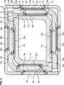
Die drei Säulenelemente
Die Wand
Das zweite Säulenelement
Das erste Rastelement
Die Vergussmasse
An den drei anderen Wänden
Auf gleichartige Weise ist das zweite Säulenelement
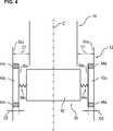
Unter Bezugnahme auf
Das zweite Säulenelement
Durch die vorstehend erläuterte Anordnung wird beim Einführen des zweiten Säulenelements
BezugszeichenlisteLIST OF REFERENCE NUMBERS
- 1010
- HubsäuleLifting column
- 1212
- erstes Säulenelementfirst column element
- 13a bis 13d13a to 13d
- erste bis vierte Wand des ersten Säulenelementsfirst to fourth walls of the first pillar member
- 1414
- zweites Säulenelementsecond column element
- 15a bis 15d15a to 15d
- erste bis vierte Wand des zweiten Säulenelementsfirst to fourth walls of the second column member
- 1616
- drittes Säulenelementthird column element
- 17a bis 17d17a to 17d
- erste bis vierte Wand des dritten Säulenelementsfirst to fourth walls of the third pillar element
- 18a bis 18b18a to 18b
- erste bis vierte Außenfläche des zweiten Säulenelementsfirst to fourth outer surfaces of the second pillar member
- 2222
- Fußplattefootplate
- 24a, 24b24a, 24b
- erste Befestigungsöffnungenfirst mounting holes
- 26a, 26b26a, 26b
- zweite Befestigungsöffnungensecond attachment openings
- 28a, 28b28a, 28b
- Entlüftungsöffnungenvents
- 30a, 30b30a, 30b
- Einfüllöffnungenfilling openings
- 32a, 32b32a, 32b
- erste Befestigungsöffnungenfirst mounting holes
- 34a, 34b34a, 34b
- zweite Befestigungsöffnungensecond attachment openings
- 36a, 36b36a, 36b
- Einfüllöffnungenfilling openings
- 4040
- GleitelementSlide
- 4242
- Gleitkörpersliding
- 4444
- Dichtungpoetry
- 4646
- erstes Rastelementfirst locking element
- 4848
- zweites Rastelementsecond locking element
- 5050
- Gleitflächesliding surface
- 5252
- Vergussmassepotting compound
- 54a bis 54d54a to 54d
- Innenflächen des ersten SäulenelementsInner surfaces of the first pillar element
- 80a bis 80d80a to 80d
- Gleitanordnungenslide assemblies
- 82a bis 82d82a to 82d
- Gleitanordnungenslide assemblies
- 9090
- Vorspannelementbiasing member
- 9292
- Vorspannkörperbiasing body
- 94a, 94c94a, 94c
- Federelementespring elements
- 100100
- weitere Hubsäuleadditional lifting column
- ZZ
- Längsachse des ersten SäulenelementsLongitudinal axis of the first column element
ZITATE ENTHALTEN IN DER BESCHREIBUNG QUOTES INCLUDE IN THE DESCRIPTION
Diese Liste der vom Anmelder aufgeführten Dokumente wurde automatisiert erzeugt und ist ausschließlich zur besseren Information des Lesers aufgenommen. Die Liste ist nicht Bestandteil der deutschen Patent- bzw. Gebrauchsmusteranmeldung. Das DPMA übernimmt keinerlei Haftung für etwaige Fehler oder Auslassungen.This list of the documents listed by the applicant has been generated automatically and is included solely for the better information of the reader. The list is not part of the German patent or utility model application. The DPMA assumes no liability for any errors or omissions.
Zitierte PatentliteraturCited patent literature
- DE 202007014791 U1[0006]DE 202007014791 U1[0006]
Claims (15)
Translated fromGermanPriority Applications (9)
| Application Number | Priority Date | Filing Date | Title |
|---|---|---|---|
| DE102014102308.0ADE102014102308A1 (en) | 2014-02-21 | 2014-02-21 | Lifting column for a medical facility |
| EP15710119.7AEP3107420B1 (en) | 2014-02-21 | 2015-02-20 | Lifting column for a medical device |
| PCT/EP2015/053652WO2015124745A1 (en) | 2014-02-21 | 2015-02-20 | Lifting column for a medical device |
| RU2016137470ARU2680567C2 (en) | 2014-02-21 | 2015-02-20 | Lifting column for medical device |
| KR1020167025930AKR20160124862A (en) | 2014-02-21 | 2015-02-20 | Lifting column for a medical device |
| JP2016553010AJP6562936B2 (en) | 2014-02-21 | 2015-02-20 | Medical device lifting column |
| PL15710119TPL3107420T3 (en) | 2014-02-21 | 2015-02-20 | Lifting column for a medical device |
| CN201580009389.9ACN106029037B (en) | 2014-02-21 | 2015-02-20 | Lifting columns for medical equipment |
| US15/218,858US10695251B2 (en) | 2014-02-21 | 2016-07-25 | Lifting column for a medical device |
Applications Claiming Priority (1)
| Application Number | Priority Date | Filing Date | Title |
|---|---|---|---|
| DE102014102308.0ADE102014102308A1 (en) | 2014-02-21 | 2014-02-21 | Lifting column for a medical facility |
Publications (1)
| Publication Number | Publication Date |
|---|---|
| DE102014102308A1true DE102014102308A1 (en) | 2015-08-27 |
Family
ID=52684192
Family Applications (1)
| Application Number | Title | Priority Date | Filing Date |
|---|---|---|---|
| DE102014102308.0ACeasedDE102014102308A1 (en) | 2014-02-21 | 2014-02-21 | Lifting column for a medical facility |
Country Status (9)
| Country | Link |
|---|---|
| US (1) | US10695251B2 (en) |
| EP (1) | EP3107420B1 (en) |
| JP (1) | JP6562936B2 (en) |
| KR (1) | KR20160124862A (en) |
| CN (1) | CN106029037B (en) |
| DE (1) | DE102014102308A1 (en) |
| PL (1) | PL3107420T3 (en) |
| RU (1) | RU2680567C2 (en) |
| WO (1) | WO2015124745A1 (en) |
Cited By (1)
| Publication number | Priority date | Publication date | Assignee | Title |
|---|---|---|---|---|
| DE102016103566A1 (en)* | 2016-02-29 | 2017-08-31 | Oelschläger Metalltechnik GmbH | Telescopic table frame component, method for producing a sliding guide and apparatus for carrying out the method |
Families Citing this family (7)
| Publication number | Priority date | Publication date | Assignee | Title |
|---|---|---|---|---|
| WO2015151127A1 (en)* | 2014-04-04 | 2015-10-08 | Pierfrancesco Pavoni | Access gate or gantry comprising an antennas assembly for therapy or imaging |
| CN208114761U (en)* | 2016-11-11 | 2018-11-20 | 通快医疗系统两合公司 | Sealing device for an operating table |
| TWI648021B (en)* | 2017-12-12 | 2019-01-21 | 林于真 | Table lifting device |
| CN108095965A (en)* | 2017-12-15 | 2018-06-01 | 温州鼎亚机械有限公司 | A kind of semi-automatic massage bed |
| US11412843B2 (en)* | 2018-05-02 | 2022-08-16 | Linak A/S | Slider element for lifting columns |
| KR102228692B1 (en) | 2020-08-13 | 2021-03-15 | 권오철 | lifting apparatus |
| KR20250001045A (en) | 2023-06-28 | 2025-01-06 | 주식회사 에스엠유니트 | Lift column with electronic brake |
Citations (8)
| Publication number | Priority date | Publication date | Assignee | Title |
|---|---|---|---|---|
| DE1924400A1 (en)* | 1968-08-29 | 1970-03-05 | Kummer Freres Sa | Procedure for installing running rails and rolling elements in a rolling slide bearing |
| CH583384A5 (en)* | 1973-04-26 | 1976-12-31 | Leitz Ernst Gmbh | |
| DE4344605C1 (en)* | 1993-12-24 | 1995-02-23 | Leica Ag | Guidance device for playfree alignment of parts, displaceable relative to one another, of an optical apparatus |
| DE10020866A1 (en)* | 2000-04-28 | 2001-10-31 | Kesseboehmer Kg | Telescopic tube system has guides between individual tubes which are produced by casting plastic in annular spaces between them |
| DE10323773A1 (en)* | 2003-05-22 | 2004-12-09 | Heinrich J. Kesseböhmer KG | telescopic extension |
| DE10323102A1 (en)* | 2003-05-20 | 2004-12-09 | Suspa Holding Gmbh | Plain bearing and process for its production |
| DE102004049058B3 (en)* | 2004-10-08 | 2006-05-24 | Hanning Elektro-Werke Gmbh & Co. Kg | Lifting column for e.g. operation table, has profile sections led against each other in middle area of side surfaces by cooperating guiding units, where guiding units exhibit undercuts, which are locked with each other |
| DE202007014791U1 (en) | 2007-10-23 | 2007-12-27 | Rk Rose + Krieger Gmbh Verbindungs- Und Positioniersysteme | Lifting column |
Family Cites Families (30)
| Publication number | Priority date | Publication date | Assignee | Title |
|---|---|---|---|---|
| US1403754A (en)* | 1920-05-06 | 1922-01-17 | Erickson Theodore | Sleeve puller |
| US2341677A (en)* | 1941-11-21 | 1944-02-15 | John H Wass | Cylinder sleeve tool |
| US2646619A (en)* | 1950-08-14 | 1953-07-28 | Hester E Mccord | Bushing remover tool |
| US3357755A (en)* | 1965-10-23 | 1967-12-12 | Danly Mach Specialties Inc | Ball bearing die set |
| US4258960A (en)* | 1976-10-06 | 1981-03-31 | Rexnord, Inc. | Wound glass filament reinforced resin slip sleeve liner |
| US4225143A (en)* | 1978-06-19 | 1980-09-30 | Advanced Thermal Systems, Inc. | Guided expansion joint |
| US4852235A (en)* | 1988-08-19 | 1989-08-01 | Trease Dwaine A | Bearing puller |
| US5317793A (en)* | 1991-03-29 | 1994-06-07 | The Boeing Company | Apparatus for installing bushings concentrically in a bore |
| US5417614A (en)* | 1994-03-14 | 1995-05-23 | General Motors Corporation | Variable length shaft assembly |
| US5560650A (en)* | 1995-07-24 | 1996-10-01 | General Motors Corporation | Intermediate steering shaft |
| FR2739093B1 (en)* | 1995-09-21 | 1999-11-26 | Jurgen Michael Knapp | LIFTING COLUMN |
| DE19623580C2 (en)* | 1996-03-27 | 2002-08-08 | Juergen Michael Knapp | Lifting column |
| US5722300A (en)* | 1996-08-16 | 1998-03-03 | General Motors Corporation | Motor vehicle steering column |
| CN2318397Y (en)* | 1997-11-21 | 1999-05-12 | 来和章 | Internal injection type single hydraulic support |
| JP2005500083A (en) | 2001-01-25 | 2005-01-06 | ヒル−ロム サービシーズ,インコーポレイティド | Hydraulic actuator device for surgical table |
| US20020102034A1 (en)* | 2001-01-31 | 2002-08-01 | Holdredge Russell T. | Apparatus with form-in-place bearing |
| GB0124126D0 (en)* | 2001-10-08 | 2001-11-28 | Eschmann Holdings Ltd | Surgical tables |
| DE10343685B4 (en)* | 2003-09-20 | 2009-03-19 | Daimler Ag | Vehicle steering column assembly |
| US7784830B2 (en)* | 2003-10-23 | 2010-08-31 | Chrysler Group Llc | Axially adjustable steering column assembly with flexible bearing sleeve |
| DE102005009348B4 (en)* | 2005-03-01 | 2013-05-29 | Manitowoc Crane Group France Sas | Adaptable sliding bearing for telescopic crane jib |
| US8127639B2 (en)* | 2005-08-16 | 2012-03-06 | Steering Solutions IP Holding Company, a Delaware corporation | Sleeve bearing for collapsible steering column |
| DE102005053753A1 (en)* | 2005-11-10 | 2007-05-16 | Maquet Gmbh & Co Kg | Hydraulic column clamping |
| FR2907858B1 (en)* | 2006-10-31 | 2011-02-25 | Mondelin Roger Sas | GUIDE PLATE DEVICE FOR TELESCOPIC COLUMNS ESPECIALLY FOR LIFTING APPLIANCES |
| WO2008070536A2 (en)* | 2006-12-05 | 2008-06-12 | Illinois Tool Works Inc. | Bushing assembly |
| US20130161127A1 (en)* | 2008-12-30 | 2013-06-27 | Allred & Associates Inc. | Ultra lightweight segmented ladder/bridge system accessories |
| CN201334914Y (en)* | 2009-02-19 | 2009-10-28 | 谢永智 | Low seam working face pillar |
| JP2010221279A (en)* | 2009-03-24 | 2010-10-07 | Kurosaki Harima Corp | Continuous casting nozzle support apparatus and method, sliding nozzle equipment and continuous casting nozzle |
| JP2010240337A (en)* | 2009-04-10 | 2010-10-28 | Morita Mfg Co Ltd | Medical examination table |
| IT1405609B1 (en)* | 2010-06-11 | 2014-01-17 | Skf Ab | LUBRICATED DRIVE UNIT FOR MOTORCYCLE FORK LEGS |
| JP6122636B2 (en)* | 2012-12-26 | 2017-04-26 | 日本トムソン株式会社 | Linear motion guide unit with plug on track rail |
- 2014
- 2014-02-21DEDE102014102308.0Apatent/DE102014102308A1/ennot_activeCeased
- 2015
- 2015-02-20WOPCT/EP2015/053652patent/WO2015124745A1/enactiveApplication Filing
- 2015-02-20RURU2016137470Apatent/RU2680567C2/ennot_activeIP Right Cessation
- 2015-02-20EPEP15710119.7Apatent/EP3107420B1/enactiveActive
- 2015-02-20PLPL15710119Tpatent/PL3107420T3/enunknown
- 2015-02-20CNCN201580009389.9Apatent/CN106029037B/enactiveActive
- 2015-02-20JPJP2016553010Apatent/JP6562936B2/enactiveActive
- 2015-02-20KRKR1020167025930Apatent/KR20160124862A/ennot_activeAbandoned
- 2016
- 2016-07-25USUS15/218,858patent/US10695251B2/enactiveActive
Patent Citations (8)
| Publication number | Priority date | Publication date | Assignee | Title |
|---|---|---|---|---|
| DE1924400A1 (en)* | 1968-08-29 | 1970-03-05 | Kummer Freres Sa | Procedure for installing running rails and rolling elements in a rolling slide bearing |
| CH583384A5 (en)* | 1973-04-26 | 1976-12-31 | Leitz Ernst Gmbh | |
| DE4344605C1 (en)* | 1993-12-24 | 1995-02-23 | Leica Ag | Guidance device for playfree alignment of parts, displaceable relative to one another, of an optical apparatus |
| DE10020866A1 (en)* | 2000-04-28 | 2001-10-31 | Kesseboehmer Kg | Telescopic tube system has guides between individual tubes which are produced by casting plastic in annular spaces between them |
| DE10323102A1 (en)* | 2003-05-20 | 2004-12-09 | Suspa Holding Gmbh | Plain bearing and process for its production |
| DE10323773A1 (en)* | 2003-05-22 | 2004-12-09 | Heinrich J. Kesseböhmer KG | telescopic extension |
| DE102004049058B3 (en)* | 2004-10-08 | 2006-05-24 | Hanning Elektro-Werke Gmbh & Co. Kg | Lifting column for e.g. operation table, has profile sections led against each other in middle area of side surfaces by cooperating guiding units, where guiding units exhibit undercuts, which are locked with each other |
| DE202007014791U1 (en) | 2007-10-23 | 2007-12-27 | Rk Rose + Krieger Gmbh Verbindungs- Und Positioniersysteme | Lifting column |
Cited By (1)
| Publication number | Priority date | Publication date | Assignee | Title |
|---|---|---|---|---|
| DE102016103566A1 (en)* | 2016-02-29 | 2017-08-31 | Oelschläger Metalltechnik GmbH | Telescopic table frame component, method for producing a sliding guide and apparatus for carrying out the method |
Also Published As
| Publication number | Publication date |
|---|---|
| JP2017506952A (en) | 2017-03-16 |
| US20160331619A1 (en) | 2016-11-17 |
| RU2680567C2 (en) | 2019-02-22 |
| EP3107420B1 (en) | 2018-08-29 |
| WO2015124745A1 (en) | 2015-08-27 |
| RU2016137470A (en) | 2018-03-22 |
| KR20160124862A (en) | 2016-10-28 |
| PL3107420T3 (en) | 2019-03-29 |
| JP6562936B2 (en) | 2019-08-21 |
| CN106029037A (en) | 2016-10-12 |
| EP3107420A1 (en) | 2016-12-28 |
| US10695251B2 (en) | 2020-06-30 |
| RU2016137470A3 (en) | 2018-08-23 |
| CN106029037B (en) | 2018-12-07 |
Similar Documents
| Publication | Publication Date | Title |
|---|---|---|
| EP3107420B1 (en) | Lifting column for a medical device | |
| EP2943090A1 (en) | Glueless composite panel and method for the glueless connection of two panel elements | |
| DE10132470A1 (en) | Radial ball bearing without play | |
| DE102013014184A1 (en) | Method for producing a linear guide device | |
| DE102017103772A1 (en) | Fastening device and mounting assembly | |
| DE112015001582B4 (en) | Motion guide device and method of making the same | |
| DE102013011469A1 (en) | Guide device for a floating caliper disc brake | |
| DE102008021884A1 (en) | Tapered roller bearing and shaft bearing for at least one tapered roller bearing | |
| EP3234400A1 (en) | Disc brake for a utility vehicle | |
| DE102008006384A1 (en) | pneumatic cylinder | |
| DE4111266C1 (en) | ||
| DE102012210014A1 (en) | Locking device for a transmission, in particular for a motor vehicle transmission | |
| WO2019121627A1 (en) | Clamping ring having a clamping section | |
| WO2006061076A1 (en) | Roller bearing for linear movements | |
| DE102023003767A1 (en) | Sliding door fittings and associated sliding door arrangement | |
| EP1534491B1 (en) | Method for sealing a throttle valve support | |
| WO2021234066A1 (en) | Telescopic strut for a device for lifting loads | |
| DE102011005244A1 (en) | Ball Screw | |
| DE202013105425U1 (en) | Spacer for a sliding guide and lifting column | |
| DE102015106084A1 (en) | Device for the automated assembly of a shell element on a connecting rod element | |
| DE202015103698U1 (en) | Desktop device and table | |
| DE102005052362A1 (en) | Throttle valve case has first housing part and second housing part, by which first housing part or second housing part is inside first circulating groove or second circulating groove | |
| DE102017116527A1 (en) | Method for precise positioning of an inner boiler in the outer boiler of a climate cabinet and climate cabinet | |
| DE102004044618B3 (en) | Damping device for stop devices has at least one damping element in an accessible aperture in first element | |
| DE102016211673A1 (en) | Method for producing a switching unit |
Legal Events
| Date | Code | Title | Description |
|---|---|---|---|
| R012 | Request for examination validly filed | ||
| R016 | Response to examination communication | ||
| R082 | Change of representative | Representative=s name:SCHAUMBURG & PARTNER PATENTANWAELTE GBR, DE Representative=s name:ZACCO DR. PETERS UND PARTNER, DE Representative=s name:ZACCO PATENTANWALTS- UND RECHTSANWALTSGESELLSC, DE | |
| R082 | Change of representative | Representative=s name:ZACCO DR. PETERS UND PARTNER, DE Representative=s name:ZACCO PATENTANWALTS- UND RECHTSANWALTSGESELLSC, DE | |
| R002 | Refusal decision in examination/registration proceedings | ||
| R003 | Refusal decision now final |