DE102014101428A1 - Method for controlling the printing elements of an inkjet print head of an inkjet printing device - Google Patents
Method for controlling the printing elements of an inkjet print head of an inkjet printing deviceDownload PDFInfo
- Publication number
- DE102014101428A1 DE102014101428A1DE102014101428.6ADE102014101428ADE102014101428A1DE 102014101428 A1DE102014101428 A1DE 102014101428A1DE 102014101428 ADE102014101428 ADE 102014101428ADE 102014101428 A1DE102014101428 A1DE 102014101428A1
- Authority
- DE
- Germany
- Prior art keywords
- voltage pulses
- ink
- vibration
- pressure point
- pressure
- Prior art date
- Legal status (The legal status is an assumption and is not a legal conclusion. Google has not performed a legal analysis and makes no representation as to the accuracy of the status listed.)
- Pending
Links
- 238000007639printingMethods0.000titleclaimsabstractdescription51
- 238000000034methodMethods0.000titleclaimsabstractdescription14
- 238000007641inkjet printingMethods0.000titleclaimsabstractdescription7
- 239000012190activatorSubstances0.000claimsabstractdescription21
- 239000000758substrateSubstances0.000description4
- 230000001419dependent effectEffects0.000description2
- 239000000463materialSubstances0.000description2
- 230000005499meniscusEffects0.000description2
- BUHVIAUBTBOHAG-FOYDDCNASA-N(2r,3r,4s,5r)-2-[6-[[2-(3,5-dimethoxyphenyl)-2-(2-methylphenyl)ethyl]amino]purin-9-yl]-5-(hydroxymethyl)oxolane-3,4-diolChemical compoundCOC1=CC(OC)=CC(C(CNC=2C=3N=CN(C=3N=CN=2)[C@H]2[C@@H]([C@H](O)[C@@H](CO)O2)O)C=2C(=CC=CC=2)C)=C1BUHVIAUBTBOHAG-FOYDDCNASA-N0.000description1
- 230000001133accelerationEffects0.000description1
- 230000004913activationEffects0.000description1
- 238000004140cleaningMethods0.000description1
- 238000011161developmentMethods0.000description1
- 230000018109developmental processEffects0.000description1
- 238000001035dryingMethods0.000description1
- 230000000694effectsEffects0.000description1
- 238000001704evaporationMethods0.000description1
- 230000008020evaporationEffects0.000description1
- 239000012530fluidSubstances0.000description1
- 238000010438heat treatmentMethods0.000description1
- 238000005457optimizationMethods0.000description1
- 230000010355oscillationEffects0.000description1
- 230000001960triggered effectEffects0.000description1
Images

Classifications
- B—PERFORMING OPERATIONS; TRANSPORTING
- B41—PRINTING; LINING MACHINES; TYPEWRITERS; STAMPS
- B41J—TYPEWRITERS; SELECTIVE PRINTING MECHANISMS, i.e. MECHANISMS PRINTING OTHERWISE THAN FROM A FORME; CORRECTION OF TYPOGRAPHICAL ERRORS
- B41J2/00—Typewriters or selective printing mechanisms characterised by the printing or marking process for which they are designed
- B41J2/005—Typewriters or selective printing mechanisms characterised by the printing or marking process for which they are designed characterised by bringing liquid or particles selectively into contact with a printing material
- B41J2/01—Ink jet
- B41J2/015—Ink jet characterised by the jet generation process
- B41J2/04—Ink jet characterised by the jet generation process generating single droplets or particles on demand
- B41J2/045—Ink jet characterised by the jet generation process generating single droplets or particles on demand by pressure, e.g. electromechanical transducers
- B41J2/04501—Control methods or devices therefor, e.g. driver circuits, control circuits
- B41J2/04541—Specific driving circuit
- B—PERFORMING OPERATIONS; TRANSPORTING
- B41—PRINTING; LINING MACHINES; TYPEWRITERS; STAMPS
- B41J—TYPEWRITERS; SELECTIVE PRINTING MECHANISMS, i.e. MECHANISMS PRINTING OTHERWISE THAN FROM A FORME; CORRECTION OF TYPOGRAPHICAL ERRORS
- B41J2/00—Typewriters or selective printing mechanisms characterised by the printing or marking process for which they are designed
- B41J2/005—Typewriters or selective printing mechanisms characterised by the printing or marking process for which they are designed characterised by bringing liquid or particles selectively into contact with a printing material
- B41J2/01—Ink jet
- B41J2/015—Ink jet characterised by the jet generation process
- B41J2/04—Ink jet characterised by the jet generation process generating single droplets or particles on demand
- B41J2/045—Ink jet characterised by the jet generation process generating single droplets or particles on demand by pressure, e.g. electromechanical transducers
- B41J2/04501—Control methods or devices therefor, e.g. driver circuits, control circuits
- B41J2/04525—Control methods or devices therefor, e.g. driver circuits, control circuits reducing occurrence of cross talk
- B—PERFORMING OPERATIONS; TRANSPORTING
- B41—PRINTING; LINING MACHINES; TYPEWRITERS; STAMPS
- B41J—TYPEWRITERS; SELECTIVE PRINTING MECHANISMS, i.e. MECHANISMS PRINTING OTHERWISE THAN FROM A FORME; CORRECTION OF TYPOGRAPHICAL ERRORS
- B41J2/00—Typewriters or selective printing mechanisms characterised by the printing or marking process for which they are designed
- B41J2/005—Typewriters or selective printing mechanisms characterised by the printing or marking process for which they are designed characterised by bringing liquid or particles selectively into contact with a printing material
- B41J2/01—Ink jet
- B41J2/015—Ink jet characterised by the jet generation process
- B41J2/04—Ink jet characterised by the jet generation process generating single droplets or particles on demand
- B41J2/045—Ink jet characterised by the jet generation process generating single droplets or particles on demand by pressure, e.g. electromechanical transducers
- B41J2/04501—Control methods or devices therefor, e.g. driver circuits, control circuits
- B41J2/04581—Control methods or devices therefor, e.g. driver circuits, control circuits controlling heads based on piezoelectric elements
- B—PERFORMING OPERATIONS; TRANSPORTING
- B41—PRINTING; LINING MACHINES; TYPEWRITERS; STAMPS
- B41J—TYPEWRITERS; SELECTIVE PRINTING MECHANISMS, i.e. MECHANISMS PRINTING OTHERWISE THAN FROM A FORME; CORRECTION OF TYPOGRAPHICAL ERRORS
- B41J2/00—Typewriters or selective printing mechanisms characterised by the printing or marking process for which they are designed
- B41J2/005—Typewriters or selective printing mechanisms characterised by the printing or marking process for which they are designed characterised by bringing liquid or particles selectively into contact with a printing material
- B41J2/01—Ink jet
- B41J2/015—Ink jet characterised by the jet generation process
- B41J2/04—Ink jet characterised by the jet generation process generating single droplets or particles on demand
- B41J2/045—Ink jet characterised by the jet generation process generating single droplets or particles on demand by pressure, e.g. electromechanical transducers
- B41J2/04501—Control methods or devices therefor, e.g. driver circuits, control circuits
- B41J2/04588—Control methods or devices therefor, e.g. driver circuits, control circuits using a specific waveform
- B—PERFORMING OPERATIONS; TRANSPORTING
- B41—PRINTING; LINING MACHINES; TYPEWRITERS; STAMPS
- B41J—TYPEWRITERS; SELECTIVE PRINTING MECHANISMS, i.e. MECHANISMS PRINTING OTHERWISE THAN FROM A FORME; CORRECTION OF TYPOGRAPHICAL ERRORS
- B41J2/00—Typewriters or selective printing mechanisms characterised by the printing or marking process for which they are designed
- B41J2/005—Typewriters or selective printing mechanisms characterised by the printing or marking process for which they are designed characterised by bringing liquid or particles selectively into contact with a printing material
- B41J2/01—Ink jet
- B41J2/015—Ink jet characterised by the jet generation process
- B41J2/04—Ink jet characterised by the jet generation process generating single droplets or particles on demand
- B41J2/045—Ink jet characterised by the jet generation process generating single droplets or particles on demand by pressure, e.g. electromechanical transducers
- B41J2/04501—Control methods or devices therefor, e.g. driver circuits, control circuits
- B41J2/04596—Non-ejecting pulses
Landscapes
- Particle Formation And Scattering Control In Inkjet Printers (AREA)
- Ink Jet (AREA)
Abstract
Translated fromGermanDescription
Translated fromGermanZum ein- oder mehrfarbigen Bedrucken eines Bedruckstoffs z.B. eines Einzelblattes oder eines bandförmigen Aufzeichnungsträgers aus verschiedensten Materialien, z.B. Papier, können Tintendruckgeräte eingesetzt werden. Der Aufbau solcher Tintendruckgeräte ist bekannt, s. z.B.
Tintendruckgeräte, die nach dem Drop on Demand (DoD) – Prinzip arbeiten, weisen einen Druckkopf oder mehrere Druckköpfe auf, die jeweils eine Mehrzahl von Druckelementen vorsehen. Ein piezoelektrisches Druckelement umfasst dabei einen Piezoaktivator, der an einem Tintenkanal angeordnet ist, der mit einer Düse verbunden ist. Die Aktivatoren regen gesteuert durch Ansteuerspannungen von einer Druckersteuerung Tintentropfen in Richtung zum Bedruckstoff an, die auf den Bedruckstoff gelenkt werden, um dort Druckpunkte für ein Druckbild aufzubringen. Diese Ansteuerspannungen werden von dem zu druckenden Bild, den Druckdaten, abgeleitet.Inkjet printing devices that operate on the Drop on Demand (DoD) principle have one or more print heads, each with a plurality of print elements. A piezoelectric pressure element in this case comprises a piezoactivator, which is arranged on an ink channel, which is connected to a nozzle. The activators rain controlled by drive voltages from a printer control rain drops of ink in the direction of the substrate, which are directed onto the substrate to apply pressure points for a printed image. These drive voltages are derived from the image to be printed, the print data.
Bei einem Tintendruckgerät ist die eingesetzte Tinte in ihrer physikalisch – chemischen Zusammensetzung an den Druckkopf angepasst, z.B. die Tinte bezüglich ihrer Viskosität. Bei geringen Druckauslastungen sind beim Druckvorgang nicht alle Druckelemente des Druckkopfes aktiviert, viele Druckelemente weisen Stillstandzeiten auf, mit der Folge, dass die Tinte im Tintenkanal dieser Druckelemente nicht bewegt wird. Wegen des Effektes des Verdunstens aus der Düsenöffnung heraus besteht die Gefahr, dass sich dann die Viskosität der Tinte verändert. Dies hat zur Folge, dass sich die Tinte im Druckelement nicht mehr optimal bewegen kann und aus der Düse austreten kann. In extremen Fällen trocknet die Tinte im Druckelement vollständig ein und verstopft dessen Düse, so dass ein Drucken mit diesem Druckelement nicht mehr möglich ist.In an ink printing apparatus, the ink used in its physicochemical composition is adapted to the printhead, e.g. the ink in terms of its viscosity. At low print utilization, not all print elements of the print head are activated during printing, and many print elements have downtimes, with the result that the ink in the ink channel of these print elements is not moved. Because of the effect of evaporation from the nozzle orifice, there is a risk that the viscosity of the ink will change. This has the consequence that the ink in the printing element can not move optimally and can escape from the nozzle. In extreme cases, the ink dries completely in the printing element and clogs its nozzle, so that printing with this printing element is no longer possible.
Ein Eintrocknen der Tinte in den Druckelementen eines Druckkopfes in deren Stillstandzeiten stellt ein Problem dar, das dadurch verhindert werden kann, dass innerhalb einem vorgegebenen Zyklus ein Spülmedium, z.B. Tinte oder Reinigungsflüssigkeit, durch alle Düsen des Druckkopfes gespült wird. Dieser Spülzyklus kann entsprechend der Druckauslastung eingestellt werden.Drying of the ink in the printing elements of a printhead during their downtime presents a problem that can be prevented by having a rinsing medium, e.g. Ink or cleaning fluid, flushed through all nozzles of the printhead. This rinse cycle can be adjusted according to the pressure load.
Weiterhin ist aus
Das von der Erfindung zu lösende Problem besteht darin, ein Verfahren anzugeben, nach dem die Druckelemente eines Druckkopfes derart einstellbar sind, dass die Gefahr einer Änderung der Viskosität der Tinte in den Tintenkanälen und den Düsen der Druckelemente möglichst klein gehalten wird, um z.B. ein Übersprechen (cross talk) zwischen benachbart liegenden Druckelementen und um eine unerwünschte Druckwellenüberlagerung in den Druckelementen zu vermeiden.The problem to be solved by the invention is to provide a method according to which the pressure elements of a printhead are adjustable so that the risk of a change in the viscosity of the ink in the ink channels and the nozzles of the printing elements is minimized, e.g. crosstalk (cross talk) between adjacent printing elements and to avoid unwanted pressure wave superposition in the printing elements.
Dieses Problem wird durch ein Verfahren gemäß den Merkmalen des Anspruchs 1 gelöst.This problem is solved by a method according to the features of
Bei dem Verfahren zur Steuerung der Druckelemente eines Tintendruckkopfes eines Tintendruckgeräts werden an die Aktivatoren der Druckelemente des Druckkopfes jeweils Ansteuerspannungen angelegt, die sich zusammensetzen aus Druckpunkt- Spanungsimpulsen, die das Ausstoßen von Tintentropfen veranlassen, und aus einem oder mehreren Vibrations-Spanungsimpulsen pro Druckpunkt-Spanungsimpuls, die die Durchmischung der Tinte in den Druckelementen über Vibrationsschwingungen veranlassen. Dabei kann die Amplitude der Vibrations-Spannungsimpulse jeweils abhängig von der Größe der den Vibrations-Spannungsimpulsen folgenden Tintentropfen, z.B. abhängig von der Dauer dieser Druckpunkt-Spannungsimpulse, gewählt werden, jedoch so, dass die Druckelemente bei Anlegen der Vibrations-Spannungsimpulse keine Tintentropfen ausstoßen. Die Vibrations-Spannungsimpulse können vor den zugeordneten Druckpunkt-Spannungsimpulsen angeordnet werden. Zweckmäßig ist, wenn zwischen den Vibrations-Spannungsimpulsen und dem zugeordneten Druckpunkt-Spannungsimpuls eine Wartezeit eingefügt wird, die z.B. mindestens eine Drucktaktperiode betragen kann. Die Wartezeit kann auch abhängig von der Druckgeschwindigkeit oder dem Tintenvolumen der Tintentropfen gewählt werden.In the method of controlling the printing elements of an ink jet printing head of an ink jet printing apparatus, driving voltages applied to the activators of the printing elements of the printing head are respectively composed of printing dot voltage pulses causing the ejection of ink droplets and one or more vibrating voltage pulses per dot voltage pulse which cause the mixing of the ink in the printing elements via vibrational vibrations. In this case, the amplitude of the vibration voltage pulses may each depend on the size of the ink drops following the vibration voltage pulses, e.g. depending on the duration of these pressure point voltage pulses, but so that the pressure elements do not eject drops of ink when the vibration voltage pulses are applied. The vibration voltage pulses may be placed before the associated pressure point voltage pulses. It is useful if between the vibration voltage pulses and the associated pressure point voltage pulse, a waiting time is inserted, the e.g. can be at least one pressure cycle period. The waiting time may also be selected depending on the printing speed or the ink volume of the ink drops.
Weiterbildungen der Erfindung ergeben sich aus den abhängigen Ansprüchen.Further developments of the invention will become apparent from the dependent claims.
Vorteile der Erfindung sind:
- • Vermeidung von Düsenausfällen während des Rampendrucks und kontinuierlichen Drucks aufgrund der – Reduzierung von Interferenzen von Druckwellen in den Druckelementen, welche zu Luftbläschen in den Tintenkanälen führen können; – Reduzierung von akustischem Crosstalk (Übersprechen auf benachbarte Tintenkanäle).
- • Reduzierte Stromaufnahme, damit geringere Erwärmung des Druckkopfes.
- • Optimierung der Prefire-Intensität d.h. Reduzierung der benötigten Anzahl von Vibrationsimpulsen.
- • Avoidance of nozzle failures during ramping and continuous printing due to: - Reduction of interference from pressure waves in the printing elements, which can lead to air bubbles in the ink channels; - Reduction of acoustic crosstalk (crosstalk to adjacent ink channels).
- • Reduced power consumption, thus less heating of the printhead.
- • Optimization of the Prefire intensity ie reduction of the required number of vibration impulses.
An Hand von Ausführungsbeispielen, die in schematischen Figuren dargestellt sind, wird die Erfindung weiter erläutert.With reference to exemplary embodiments, which are illustrated in schematic figures, the invention will be further explained.
Es zeigen:Show it:
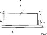
Im Betrieb wird den in der Düsenplatte
Das durch die Tintentropfen auf dem Aufzeichnungsträger erzeugte Druckbild wird durch das Volumen der von den Düsen
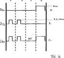
Die
- – von Druckpunkt-Spannungsimpulsen UD für Aktivatoren von Druckelementen, um Tintentropfen unterschiedlichen Volumens oder Größe zu erzeugen (
2a ,3a ,4a ); - – von Vibrations-Spannungsimpulsen UP, die die Aktivatoren zu Vibrationen in den Druckelementen veranlassen (
2b ,3b ,4b ).
- Of pressure point voltage pulses UD for activators of printing elements to produce ink droplets of different volume or size (
2a .3a .4a ); - - Vibrations voltage pulses UP , which cause the activators to vibrate in the printing elements (
2 B .3b .4b ).
Um einer unerwünschten Änderung der Viskosität der Tinte in den Druckelementen entgegen zu wirken, können z.B. vor Auftreten eines Druckpunkt-Spannungsimpulses UD Prefire- oder Vibrations-Spannungsimpulse UP zur Erzeugung von Vibrationsschwingungen in den Druckelementen vorgesehen werden. Die Anzahl der Vibrations-Spannungsimpulse UP und deren Dauer ist in Abhängigkeit des Einsatzfalles wählbar. Die Amplitude der Vibrations-Spannungsimpulse UP wird dabei kleiner oder gleich gewählt als die zugeordneten Druckpunkt-Spannungsimpulse UD, jedoch wird die Amplitude der Vibrations-Spannungsimpulse UP abhängig von der Impulsdauer der Druckpunkt-Spannungsimpulse und damit der Größe der gefeuerten Tintentropfen eingestellt. Je größer die Impulsdauer des Druckpunkt-Spannungsimpulses UD ist, umso größer ist die Amplitude der zugeordneten Vibrations- Spannungsimpulse UP, wobei die Amplitude der Vibrations- Spannungsimpulse UP immer so zu wählen ist, dass die Druckelemente keinen Tintentropfen ausstoßen.To counteract an undesirable change in the viscosity of the ink in the printing elements, for example, before the occurrence of a pressure point voltage pulse UD Prefire or vibration voltage pulses UP are provided for generating vibration oscillations in the printing elements. The number of vibration voltage pulses UP and their duration is dependent of the application selectable. The amplitude of the vibration voltage pulses UP is chosen to be less than or equal to the associated pressure point voltage pulses UD , however, the amplitude of the vibration voltage pulses UP is set depending on the pulse duration of the pressure point voltage pulses and thus the size of the fired ink drops. The greater the pulse duration of the pressure point voltage pulse UD , the greater the amplitude of the associated vibration voltage pulses UP , the amplitude of the vibration voltage pulses UP always having to be selected so that the pressure elements do not eject any drops of ink.
Eine mögliche Wellenform von Vibrations- Spannungsimpulse UP1 bei einem Druckpunkt-Spannungsimpuls UD1 im Falle der
Eine Wellenform von Vibrations- Spannungsimpulsen UP2 bei einem Druckpunkt-Spannungsimpuls UD2 im Falle der
Eine Wellenform von Vibrations-Spannungsimpulsen UP3 bei einem Druckpunkt-Spannungsimpuls UD3 im Falle der
Die den Aktivatoren der Druckelemente zugeführte Ansteuerspannung UKsetzt sich dann aus einer Kombination der Vibrations-Spannungsimpulse UPund des Druckpunkt-Spannungsimpulses UDzusammen. In den
Um Interferenzen der Druckwellen, die von den Vibrations- Spannungsimpulsen UP ausgelöst werden, mit den Druckwellen der Druckpunkt-Spannungsimpulsen UD zu vermeiden, kann zwischen den Vibrations-Spannungsimpulsen UP und den zugeordneten Druckpunkt-Spannungsimpulsen UD eine Wartezeit WT einge- halten werden, z.B. kann als Wartezeit WT mindestens eine Drucktaktperiode T gewählt werden (z.B. T = Pixel/((a0·t + v0)), wobei t = Zeit, v0 = Substratgeschwindigkeit, a0 = Substratbeschleunigung ist). Die an die Druckelemente angelegte Ansteuerspannung UK setzt sich dann aus einer Folge von Vibrations-Spannungsimpulsen UP, einer Wartezeit WT und einem Druckpunkt-Spannungsimpuls UDzusammen. Diese Folge ist für die Druckpunkt-Spannungsimpulse UD der
Die Anzahl der Vibrations-Spannungsimpulse UP, die vor einem Druckpunkt-Spannungsimpuls UD angeordnet werden, kann entsprechend dem Anwendungsfall gewählt werden, z.B. von der Druckgeschwindigkeit abhängen. Die Dauer der Druckpunkt-Spannungsimpulse UD hängt von der Größe der Tintentropfen ab. Die Amplitude der Vibrations-Spannungsimpulse UPwird in Abhängigkeit der Dauer der Druckpunkt-Spannungsimpulse UDgewählt und kann in Testreihen ermittelt werden. Dabei ist zu beachten, dass die Größe der Vibrations-Spannungsimpulse UP nur so gewählt werden darf, dass die mit den Vibrations-Spannungsimpulsen UPallein angesteuerten Druckelemente keine Tintentropfen abgeben.The number of vibration voltage pulses UP , which are arranged in front of a pressure point voltage pulse UD , can be selected according to the application, for example, depend on the printing speed. The duration of the pressure point voltage pulses UD depends on the size of the ink drops. The amplitude of the vibration voltage pulses UP is selected as a function of the duration of the pressure point voltage pulses UD and can be determined in test series. It should be noted that the size of the vibration voltage pulses UP may only be selected so that the pressure elements driven by the vibration voltage pulses UP alone do not emit drops of ink.
BezugszeichenlisteLIST OF REFERENCE NUMBERS
- DKDK
- Druckkopfprinthead
- 11
- DruckkopfgehäusePrinthead housing
- 22
- Düsejet
- 33
- Düsenplattenozzle plate
- 44
- Versorgungsleitung für TinteSupply line for ink
- 55
- Versorgungsleitung für TinteSupply line for ink
- 66
- Anschlussklemmeterminal
- 77
- Anschlussklemmeterminal
- UDUD
- Druckpunkt-SpannungsimpulsTactile-voltage pulse
- UPUP
- Vibrations-SpannungsimpulsVibration voltage pulse
- UKUK
- Ansteuerspannung für die DruckelementeDrive voltage for the printing elements
- VV
- Spannungtension
- WTWT
- Wartezeitwaiting period
- TT
- DrucktaktperiodePrint clock period
ZITATE ENTHALTEN IN DER BESCHREIBUNG QUOTES INCLUDE IN THE DESCRIPTION
Diese Liste der vom Anmelder aufgeführten Dokumente wurde automatisiert erzeugt und ist ausschließlich zur besseren Information des Lesers aufgenommen. Die Liste ist nicht Bestandteil der deutschen Patent- bzw. Gebrauchsmusteranmeldung. Das DPMA übernimmt keinerlei Haftung für etwaige Fehler oder Auslassungen.This list of the documents listed by the applicant has been generated automatically and is included solely for the better information of the reader. The list is not part of the German patent or utility model application. The DPMA assumes no liability for any errors or omissions.
Zitierte PatentliteraturCited patent literature
- EP 0788882 B1[0001, 0005]EP 0788882 B1[0001, 0005]
- DE 69736991 T2[0005]DE 69736991 T2[0005]
Claims (9)
Translated fromGermanPriority Applications (3)
| Application Number | Priority Date | Filing Date | Title |
|---|---|---|---|
| DE102014101428.6ADE102014101428A1 (en) | 2014-02-05 | 2014-02-05 | Method for controlling the printing elements of an inkjet print head of an inkjet printing device |
| US14/614,661US9205645B2 (en) | 2014-02-05 | 2015-02-05 | Method to control the printing elements of an ink print head of an ink printing apparatus |
| JP2015021418AJP2015147419A (en) | 2014-02-05 | 2015-02-05 | Method for controlling printing elements of ink print head of ink printing apparatus |
Applications Claiming Priority (1)
| Application Number | Priority Date | Filing Date | Title |
|---|---|---|---|
| DE102014101428.6ADE102014101428A1 (en) | 2014-02-05 | 2014-02-05 | Method for controlling the printing elements of an inkjet print head of an inkjet printing device |
Publications (1)
| Publication Number | Publication Date |
|---|---|
| DE102014101428A1true DE102014101428A1 (en) | 2015-08-06 |
Family
ID=53546918
Family Applications (1)
| Application Number | Title | Priority Date | Filing Date |
|---|---|---|---|
| DE102014101428.6APendingDE102014101428A1 (en) | 2014-02-05 | 2014-02-05 | Method for controlling the printing elements of an inkjet print head of an inkjet printing device |
Country Status (3)
| Country | Link |
|---|---|
| US (1) | US9205645B2 (en) |
| JP (1) | JP2015147419A (en) |
| DE (1) | DE102014101428A1 (en) |
Cited By (5)
| Publication number | Priority date | Publication date | Assignee | Title |
|---|---|---|---|---|
| DE102017110813A1 (en) | 2017-05-18 | 2018-11-22 | Océ Holding B.V. | Method of controlling printing elements of an ink jet print head |
| DE102017118258A1 (en) | 2017-08-10 | 2019-02-14 | Océ Holding B.V. | Method and apparatus for controlling printing elements of an ink jet print head |
| DE102018212063B3 (en)* | 2018-07-19 | 2019-08-14 | Heidelberger Druckmaschinen Ag | Cross-talk avoidance |
| DE102020111099A1 (en) | 2020-04-23 | 2021-10-28 | Canon Production Printing Holding B.V. | Printing device and method for determining print speed-dependent print data for the operation of a nozzle |
| US11207882B2 (en) | 2019-02-27 | 2021-12-28 | Canon Production Printing Holding B.V. | Method and device for controlling an actuator of an inkjet printing system |
Families Citing this family (3)
| Publication number | Priority date | Publication date | Assignee | Title |
|---|---|---|---|---|
| JP6716962B2 (en)* | 2016-03-03 | 2020-07-01 | セイコーエプソン株式会社 | Liquid ejection device and liquid ejection system |
| JP6932909B2 (en) | 2016-09-26 | 2021-09-08 | セイコーエプソン株式会社 | Liquid injection device, flushing adjustment method, control program of liquid injection device and recording medium |
| JP6907604B2 (en)* | 2017-03-06 | 2021-07-21 | セイコーエプソン株式会社 | Control method of liquid injection device and liquid injection device |
Citations (5)
| Publication number | Priority date | Publication date | Assignee | Title |
|---|---|---|---|---|
| EP0788882B1 (en) | 1996-01-29 | 2002-07-17 | Seiko Epson Corporation | Ink-jet recording head |
| US20040113960A1 (en)* | 2002-09-12 | 2004-06-17 | Takahiro Usui | Film forming apparatus and method of driving same, device manufacturing method, device manufacturing apparatus, and device |
| DE60125265T2 (en)* | 2000-03-27 | 2007-07-05 | Seiko Epson Corp. | Device for ejecting liquid from nozzles with Mikrovibrationsanlage |
| US20070285448A1 (en)* | 2006-06-12 | 2007-12-13 | Fuji Xerox Co., Ltd. | Liquid drop expelling head and image forming device provided therewith |
| DE102012107776A1 (en)* | 2012-08-23 | 2014-02-27 | Océ Printing Systems GmbH & Co. KG | Method for performing a printing interruption in the printing operation of an ink printing system with at least one printing device |
Family Cites Families (9)
| Publication number | Priority date | Publication date | Assignee | Title |
|---|---|---|---|---|
| JP3613297B2 (en)* | 1996-01-29 | 2005-01-26 | セイコーエプソン株式会社 | Inkjet recording device |
| US6029896A (en)* | 1997-09-30 | 2000-02-29 | Microfab Technologies, Inc. | Method of drop size modulation with extended transition time waveform |
| JP3528592B2 (en)* | 1998-04-24 | 2004-05-17 | セイコーエプソン株式会社 | Ink jet recording device |
| JP3741186B2 (en)* | 1999-03-31 | 2006-02-01 | セイコーエプソン株式会社 | Inkjet recording device |
| JP2001232798A (en)* | 2000-02-25 | 2001-08-28 | Hitachi Koki Co Ltd | INK JET RECORDING APPARATUS AND RECORDING METHOD THEREOF |
| JP2001353865A (en)* | 2000-06-15 | 2001-12-25 | Ricoh Co Ltd | Ink jet recording device |
| JP4730029B2 (en)* | 2005-09-09 | 2011-07-20 | 富士ゼロックス株式会社 | Droplet discharge recording head driving method and droplet discharge recording apparatus |
| US9299959B2 (en)* | 2012-06-06 | 2016-03-29 | Panasonic Intellectual Property Management Co., Ltd. | Inkjet device and manufacturing method for organic el device |
| JP2014076561A (en)* | 2012-10-10 | 2014-05-01 | Seiko Epson Corp | Liquid jet device and liquid jet method |
- 2014
- 2014-02-05DEDE102014101428.6Apatent/DE102014101428A1/enactivePending
- 2015
- 2015-02-05USUS14/614,661patent/US9205645B2/enactiveActive
- 2015-02-05JPJP2015021418Apatent/JP2015147419A/enactivePending
Patent Citations (6)
| Publication number | Priority date | Publication date | Assignee | Title |
|---|---|---|---|---|
| EP0788882B1 (en) | 1996-01-29 | 2002-07-17 | Seiko Epson Corporation | Ink-jet recording head |
| DE69736991T2 (en) | 1996-01-29 | 2007-07-12 | Seiko Epson Corp. | Ink jet recording head |
| DE60125265T2 (en)* | 2000-03-27 | 2007-07-05 | Seiko Epson Corp. | Device for ejecting liquid from nozzles with Mikrovibrationsanlage |
| US20040113960A1 (en)* | 2002-09-12 | 2004-06-17 | Takahiro Usui | Film forming apparatus and method of driving same, device manufacturing method, device manufacturing apparatus, and device |
| US20070285448A1 (en)* | 2006-06-12 | 2007-12-13 | Fuji Xerox Co., Ltd. | Liquid drop expelling head and image forming device provided therewith |
| DE102012107776A1 (en)* | 2012-08-23 | 2014-02-27 | Océ Printing Systems GmbH & Co. KG | Method for performing a printing interruption in the printing operation of an ink printing system with at least one printing device |
Cited By (7)
| Publication number | Priority date | Publication date | Assignee | Title |
|---|---|---|---|---|
| DE102017110813A1 (en) | 2017-05-18 | 2018-11-22 | Océ Holding B.V. | Method of controlling printing elements of an ink jet print head |
| DE102017118258A1 (en) | 2017-08-10 | 2019-02-14 | Océ Holding B.V. | Method and apparatus for controlling printing elements of an ink jet print head |
| US10569536B2 (en) | 2017-08-10 | 2020-02-25 | Océ Holding B.V. | Method and device for controlling printing elements of an ink print head |
| DE102018212063B3 (en)* | 2018-07-19 | 2019-08-14 | Heidelberger Druckmaschinen Ag | Cross-talk avoidance |
| US11207882B2 (en) | 2019-02-27 | 2021-12-28 | Canon Production Printing Holding B.V. | Method and device for controlling an actuator of an inkjet printing system |
| DE102020111099A1 (en) | 2020-04-23 | 2021-10-28 | Canon Production Printing Holding B.V. | Printing device and method for determining print speed-dependent print data for the operation of a nozzle |
| US11660859B2 (en) | 2020-04-23 | 2023-05-30 | Canon Production Printing Holding B.V. | Printing device and method for determining print speed-dependent print data for the operation of a nozzle |
Also Published As
| Publication number | Publication date |
|---|---|
| US9205645B2 (en) | 2015-12-08 |
| JP2015147419A (en) | 2015-08-20 |
| US20150217564A1 (en) | 2015-08-06 |
Similar Documents
| Publication | Publication Date | Title |
|---|---|---|
| DE102014101428A1 (en) | Method for controlling the printing elements of an inkjet print head of an inkjet printing device | |
| DE69714161T2 (en) | INK JET PRINT HEAD AND CONTROL METHOD THEREFOR | |
| DE60006332T2 (en) | Liquid jet device, method for its control and computer-readable storage medium storing the method | |
| DE69212564T2 (en) | Apparatus and method for driving an ink jet recording head | |
| DE69809201T2 (en) | Driving method of an inkjet printhead | |
| DE69405885T2 (en) | Apparatus and method for driving an ink jet recording head | |
| DE60101297T2 (en) | Ink jet recording device and driving method therefor | |
| DE69603899T2 (en) | Drive device for generating a jet of ink droplets | |
| DE3227637C2 (en) | Control circuit for ink jet printers | |
| DE60131942T2 (en) | Ink jet recording apparatus | |
| DE69504975T2 (en) | METHOD FOR DRIVING AN INK JET PRINT HEAD | |
| DE3382649T2 (en) | COLOR JET PRINTER AND OPERATING METHOD. | |
| DE102014106424A1 (en) | Method for controlling vibration cycles in the printing operation of an ink printing system with at least one printing device | |
| DE3804456C2 (en) | ||
| DE102012110187A1 (en) | Method for performing a printing interruption in the printing operation of an ink printing system with at least one printing device | |
| DE69421301T2 (en) | Inkjet device | |
| DE102017118258A1 (en) | Method and apparatus for controlling printing elements of an ink jet print head | |
| DE69419969T2 (en) | Provided with the ink jet recording head and recording device | |
| DE60303847T2 (en) | Device for ejecting very small droplets | |
| DE69318592T2 (en) | Method and device for suppressing capillary waves in an inkjet printer | |
| DE102016116195A1 (en) | Method for controlling actuators of an ink printing system | |
| DE69938385T2 (en) | Drive apparatus and method of a retrieving ink jet printhead | |
| DE60132595T2 (en) | INK-JET PRINTING | |
| DE102010036839A1 (en) | A method of renewing the ink in nozzles of an ink print head in an ink printing apparatus | |
| DE102005011920A1 (en) | inkjet device |
Legal Events
| Date | Code | Title | Description |
|---|---|---|---|
| R012 | Request for examination validly filed | ||
| R016 | Response to examination communication | ||
| R082 | Change of representative | Representative=s name:SCHAUMBURG & PARTNER PATENTANWAELTE GBR, DE Representative=s name:SCHAUMBURG & PARTNER PATENTANWAELTE MBB, DE Representative=s name:SCHAUMBURG UND PARTNER PATENTANWAELTE MBB, DE | |
| R081 | Change of applicant/patentee | Owner name:CANON PRODUCTION PRINTING GERMANY GMBH & CO. K, DE Free format text:FORMER OWNER: OCE PRINTING SYSTEMS GMBH & CO. KG, 85586 POING, DE | |
| R082 | Change of representative | Representative=s name:SCHAUMBURG UND PARTNER PATENTANWAELTE MBB, DE |