DE102014017534A1 - Display device which can be placed on the head of a user - Google Patents
Display device which can be placed on the head of a userDownload PDFInfo
- Publication number
- DE102014017534A1 DE102014017534A1DE102014017534.0ADE102014017534ADE102014017534A1DE 102014017534 A1DE102014017534 A1DE 102014017534A1DE 102014017534 ADE102014017534 ADE 102014017534ADE 102014017534 A1DE102014017534 A1DE 102014017534A1
- Authority
- DE
- Germany
- Prior art keywords
- display device
- image
- imaging optics
- interface
- user
- Prior art date
- Legal status (The legal status is an assumption and is not a legal conclusion. Google has not performed a legal analysis and makes no representation as to the accuracy of the status listed.)
- Withdrawn
Links
Images


Classifications
- G—PHYSICS
- G02—OPTICS
- G02B—OPTICAL ELEMENTS, SYSTEMS OR APPARATUS
- G02B27/00—Optical systems or apparatus not provided for by any of the groups G02B1/00 - G02B26/00, G02B30/00
- G02B27/01—Head-up displays
- G02B27/017—Head mounted
- G02B27/0172—Head mounted characterised by optical features
- G—PHYSICS
- G02—OPTICS
- G02B—OPTICAL ELEMENTS, SYSTEMS OR APPARATUS
- G02B13/00—Optical objectives specially designed for the purposes specified below
- G02B13/18—Optical objectives specially designed for the purposes specified below with lenses having one or more non-spherical faces, e.g. for reducing geometrical aberration
- G—PHYSICS
- G02—OPTICS
- G02B—OPTICAL ELEMENTS, SYSTEMS OR APPARATUS
- G02B27/00—Optical systems or apparatus not provided for by any of the groups G02B1/00 - G02B26/00, G02B30/00
- G02B27/01—Head-up displays
- G02B27/017—Head mounted
- G02B2027/0178—Eyeglass type
- G—PHYSICS
- G02—OPTICS
- G02B—OPTICAL ELEMENTS, SYSTEMS OR APPARATUS
- G02B25/00—Eyepieces; Magnifying glasses
- G02B25/001—Eyepieces
- G—PHYSICS
- G06—COMPUTING OR CALCULATING; COUNTING
- G06T—IMAGE DATA PROCESSING OR GENERATION, IN GENERAL
- G06T19/00—Manipulating 3D models or images for computer graphics
- G06T19/006—Mixed reality
Landscapes
- Physics & Mathematics (AREA)
- General Physics & Mathematics (AREA)
- Optics & Photonics (AREA)
Abstract
Translated fromGermanDescription
Translated fromGermanDie vorliegende Erfindung betrifft eine Anzeigevorrichtung mit einer auf den Kopf eines Benutzers aufsetzbaren Haltevorrichtung und einer mechanisch mit der Haltevorrichtung verbundenen ersten Abbildungsoptik, die dafür ausgebildet ist, ein in einer Bildebene erzeugtes Bild als virtuelles Bild so abzubilden, dass es der Benutzer im auf dem Kopf aufgesetzten Zustand der Haltevorrichtung mit einem ersten Auge wahrnehmen kann.The present invention relates to a display device with a holding device which can be placed on the head of a user and a first imaging optics mechanically connected to the holding device, which is designed to image an image generated in an image plane as a virtual image in such a way that it is turned upside down by the user can perceive patch state of the holding device with a first eye.
Solche Anzeigevorrichtungen können insbesondere so ausgebildet sein, dass der Benutzer nur noch die durch die Anzeigevorrichtung erzeugten Bilder und nicht mehr die Umgebung wahrnehmen kann. Solche Anzeigevorrichtungen werden auch als HMD-Vorrichtung (Head Mounted Display)-Vorrichtung oder auch als VR-Brille (Virtuelle-Realität-Brille) bezeichnet. Da der Benutzer nur noch die durch die Anzeigevorrichtung erzeugten Bilder und nicht mehr die Umgebung wahrnehmen kann, taucht er quasi in eine virtuelle Realität ein, was einen starken Eindruck hinterlässt.Such display devices may in particular be designed so that the user can only perceive the images generated by the display device and no longer the environment. Such display devices are also referred to as HMD device (Head Mounted Display) device or as VR glasses (virtual reality glasses). Since the user can only perceive the images generated by the display device and no longer the environment, he immerses virtually in a virtual reality, which leaves a strong impression.
Solche Anzeigevorrichtungen sollen, da sie auf dem Kopf getragen werden, möglichst leicht sein und gleichzeitig soll eine möglichst gute Abbildung des virtuellen Bildes mit großem Sichtfeld bereitgestellt werden, was zu einem erhöhten Gewicht der ersten Abbildungsoptik führt, da sie dazu z. B. mehrere Linsen aufweist.Such display devices, since they are worn on the head, should be as light as possible and at the same time the best possible image of the virtual image with a large field of view should be provided, which leads to an increased weight of the first imaging optics, since they z. B. has multiple lenses.
Ausgehend hiervon ist es daher Aufgabe der Erfindung eine Anzeigevorrichtung mit einer auf den Kopf eines Benutzers aufsetzbaren Haltevorrichtung und einer mechanisch mit der Haltevorrichtung verbundenen ersten Abbildungsoptik, die dafür ausgebildet ist, ein in einer Bildebene erzeugtes Bild als virtuelles Bild so abzubilden, dass es der Benutzer im auf dem Kopf aufgesetzten Zustand der Haltevorrichtung mit einem ersten Auge wahrnehmen kann, so weiterzubilden, dass die eingangs genannten Schwierigkeiten möglichst vollständig überwunden werden können.Proceeding from this, it is therefore an object of the invention to provide a display device with a holding device which can be placed on the head of a user and a first imaging optics mechanically connected to the holding device, which is designed to image a picture generated in an image plane as a virtual image in such a way that it is the user perceive in the mounted on the head state of the holding device with a first eye, so educate, that the difficulties mentioned above can be overcome as completely as possible.
Erfindungsgemäß wird die Aufgabe mit einer Anzeigevorrichtung, die eine auf den Kopf eines Benutzers aufsetzbaren Haltevorrichtung und eine mechanisch mit der Haltevorrichtung verbundenen ersten Abbildungsoptik aufweist, die dafür ausgebildet ist, ein in einer Bildebene erzeugtes Bild als virtuelles Bild so abzubilden, dass es der Benutzer im auf dem Kopf aufgesetzten Zustand der Haltevorrichtung mit einem ersten Auge wahrnehmen kann, gelöst, wobei die erste Abbildungsoptik als abbildendes Element genau eine erste Linse mit einer ersten und einer zweiten Grenzfläche aufweist, wobei beide Grenzflächen jeweils asphärisch gekrümmt sind.According to the invention, the object is provided with a display device which has a holding device which can be placed on the head of a user and a first imaging optics mechanically connected to the holding device, which is designed to image a picture generated in an image plane as a virtual image in such a way that the user in FIG solved, wherein the first imaging optics as the imaging element exactly one first lens having a first and a second interface, wherein both boundary surfaces are each aspherically curved.
Damit ist es möglich, mit nur einer einzigen Linse eine ausreichend gute Abbildung bereitzustellen. Da die erste Abbildungsoptik genau eine erste Linse (und keine weiteren abbildenden optischen Elemente) aufweist, kann das Gewicht der Anzeigevorrichtung gering gehalten werden.This makes it possible to provide a sufficiently good image with only a single lens. Since the first imaging optics has exactly one first lens (and no further imaging optical elements), the weight of the display device can be kept low.
Die erste und zweite Grenzfläche weisen bevorzugt unterschiedliche sphärische Krümmungen auf. Insbesondere kann das Verhältnis des Betrages der Scheitelkrümmung der ersten Grenzfläche, die der Bildebene zugewandt ist, zum Betrag der Scheitelkrümmung der zweiten Grenzfläche im Bereich von 1,2 bis 1,8 liegen. Damit ist eine ausreichende Korrektur des Astigmatismus möglich, wodurch die gewünschte Abbildungsqualität bereitgestellt werden kann.The first and second boundary surfaces preferably have different spherical curvatures. In particular, the ratio of the amount of crest curvature of the first interface facing the image plane to the amount of crest curvature of the second interface may be in the range of 1.2 to 1.8. Thus, a sufficient correction of the astigmatism is possible, whereby the desired imaging quality can be provided.
Insbesondere kann die zweite Grenzfläche als Hyperboloid ohne Deformationen höherer Ordnung und/oder kann die erste Grenzfläche als Hyperboloid mit Deformationen höherer Ordnungen ausgebildet sein.In particular, the second interface may be formed as a hyperboloid without higher order deformations, and / or the first interface may be formed as a hyperboloid with higher order deformations.
Die erste Abbildungsoptik kann frei von Umlenkelementen zur Strahlengangfaltung sein.The first imaging optics can be free of deflecting elements for beam path folding.
Die erste Linse kann aus Kunststoff gebildet sein. Dies führt zu einem geringen Gewicht. Beispielsweise kann sie aus PMMA gebildet sein. Dies führt zu einer Verringerung der unerwünschten chromatischen Aberrationen, da PMMA eine geringe Dispersion aufweist.The first lens may be formed of plastic. This leads to a low weight. For example, it may be formed of PMMA. This leads to a reduction in the undesirable chromatic aberrations, since PMMA has a low dispersion.
Ferner kann vor der ersten Grenzfläche und somit zwischen der ersten Grenzfläche und der Bildebene eine Blende positioniert sein. Damit können Strahlen mit starker Aberration abgeschattet werden, die sonst von der ersten Linse in unerwünschter Weise zur Austrittspupille der ersten Abbildungsoptik gelenkt werden würden.Furthermore, a diaphragm may be positioned in front of the first interface and thus between the first interface and the image plane. Thus, rays with strong aberration can be shaded, which would otherwise be directed by the first lens in an undesired manner to the exit pupil of the first imaging optics.
Der Abstand zwischen der zweiten Grenzfläche und der Austrittspupille der ersten Abbildungsoptik kann im Bereich von 5 bis 25 mm, insbesondere im Bereich von 13 bis 20 mm liegen.The distance between the second interface and the exit pupil of the first imaging optics may be in the range of 5 to 25 mm, in particular in the range of 13 to 20 mm.
Das bereitgestellte Sichtfeld kann in diagonaler Richtung einen Wert zwischen 65° und 105° aufweisen. The provided field of view may have a value between 65 ° and 105 ° in the diagonal direction.
Der Abstand zwischen der Austrittspupille der ersten Abbildungsoptik und der Bildebene kann im Bereich von 50 bis 70 mm liegen.The distance between the exit pupil of the first imaging optics and the image plane may be in the range of 50 to 70 mm.
Die Austrittspupille der ersten Abbildungsoptik kann eine maximale Ausdehnung von größer oder gleich 3 mm, bevorzugt von größer oder gleich 5 mm, aufweisen.The exit pupil of the first imaging optics may have a maximum extension of greater than or equal to 3 mm, preferably greater than or equal to 5 mm.
Die Anzeigevorrichtung ist insbesondere so ausgelegt, dass das in der Bildebene erzeugte Bild eine Diagonale von 50 mm oder weniger aufweist.In particular, the display device is designed such that the image formed in the image plane has a diagonal of 50 mm or less.
Die erste Abbildungsoptik ist so ausgelegt, dass der Astigmatismus als korrigiert angesehen werden kann, wohingegen eine Verzerrung und eine laterale chromatische Aberration zugelassen sind. Das in der Bildebene erzeugte Bild wird dann bevorzugt mit einer entsprechenden gegenläufigen Verzerrung und einer entsprechenden gegenläufigen lateralen chromatischen Aberration erzeugt, so dass das abgebildete virtuelle Bild ohne Verzerrung oder mit geringer Verzerrung und ohne chromatische Aberration oder geringer lateraler chromatischer Aberration abgebildet ist.The first imaging optic is designed so that the astigmatism can be considered corrected, whereas distortion and lateral chromatic aberration are allowed. The image formed in the image plane is then preferably generated with a corresponding opposite distortion and a corresponding opposite lateral chromatic aberration so that the imaged virtual image is imaged without distortion or with low distortion and without chromatic aberration or with little lateral chromatic aberration.
Ferner ist die erste Abbildungsoptik so optimiert, dass die noch vorhandene Feldkrümmung durch Akkommodation mittels des Auges kompensiert werden kann.Furthermore, the first imaging optics is optimized so that the remaining field curvature can be compensated by accommodation by means of the eye.
Insbesondere sind die asphärisch gekrümmten Grenzflächen so ausgebildet, dass sie die sphärische Aberration korrigieren. Bevorzugt können sie auch Aberrationen höherer Ordnung korrigieren. Des weiteren kann die erste Abbildungsoptik so ausgelegt sein, dass ihr Petzval-Radius im Bereich von –55 bis –49 liegt.In particular, the aspherically curved interfaces are designed to correct the spherical aberration. Preferably, they can also correct higher order aberrations. Furthermore, the first imaging optics may be designed so that their Petzval radius is in the range of -55 to -49.
Ferner ist die erste Abbildungsoptik bevorzugt so ausgelegt, dass die von der ersten Grenzfläche bedingte Winkelabweichung der Strahlen durch die von der zweiten Grenzfläche bedingte Winkelabweichung der Strahlen bei der Abbildung kompensiert ist. Hierunter wird insbesondere verstanden, dass |nLuft·sinβ1 – nSubsrat·sinβ2 + nLuft·sinβ3 – nSubstrat·sinβ2| Null oder nahezu Null beträgt, wobei die Winkel sinβ1, sinβ2 und sinβ3 jeweils der der Austrittspupille
Die Anzeigevorrichtung kann ferner ein mechanisch mit der Haltevorrichtung verbundenes Bildmodul, das einen Bildschirm, auf dem das Bild in der Bildebene erzeugt wird, aufweisen. Das Bildmodul kann eine Steuereinheit zur Ansteuerung des Bildschirms und eine Sensoreinheit zum Erfassen einer Bewegung des Bildmoduls aufweisen. Die Sensoreinheit kann eingerichtet sein, der Steuereinheit Signale zuzuführen. Die Steuereinheit kann eingerichtet sein, aus den Signalen ein durchgeführtes Antippen der Haltevorrichtung zu erkennen und in Abhängigkeit des erkannten Antippens eine Änderung des auf dem Bildschirm erzeugten Bildes und/oder die Steuerung einer auf dem Bildmodul ausgeführten Anwendung, die Inhalte bereitstellt, die im auf dem Bildschirm erzeugten Bild enthalten sind, zu bewirken.The display device may further include an image module mechanically coupled to the fixture having a screen on which the image is formed in the image plane. The image module may have a control unit for controlling the screen and a sensor unit for detecting a movement of the image module. The sensor unit can be set up to supply signals to the control unit. The control unit may be configured to detect from the signals a performed tap of the holding device and depending on the detected tap a change of the image generated on the screen and / or the control of an executed on the image module application that provides content that in on the Screen generated image are to effect.
Ein solches Antippen oder Anstoßen der Haltevorrichtung kann diskret und auch in lauterer Umgebung durchgeführt werden, ohne dass dadurch die Eingabe verfälscht wird. Somit kann eine diskrete und sichere Steuerung der Anzeigevorrichtung erfolgen.Such a tapping or abutment of the holding device can be carried out discretely and also in a louder environment, without thereby distorting the input. Thus, a discrete and secure control of the display device can take place.
Bei der erfindungsgemäßen Anzeigevorrichtung kann somit über ein Tippen, Stoßen oder Klopfen gegen die Haltevorrichtung eine Eingabe durchgeführt werden. Erfindungsgemäß wird die Haltevorrichtung an sich als Eingabeschnittstelle genutzt, die auf eine Berührung der Haltevorrichtung (insbesondere ein Tippen, Stoßen oder Klopfen gegen die Haltevorrichtung) sensitiv ist, wobei dazu die Haltevorrichtung nicht speziell angepaßt werden muß. Die Haltevorrichtung kann so wie sie ist als Eingabeschnittstelle genutzt werden, da die Messung der durchgeführten Interaktion (das Tippen, Stollen, Klopfen, etc.) mit der Haltevorrichtung mittels der Sensoreinheit und die Auswertung der Meßsignale mittels der Steuereinheit erfolgt, die beide Teil des Bildmoduls sind.In the case of the display device according to the invention, an input can thus be made by tapping, pushing or tapping against the holding device. According to the holding device is used as an input interface, which is sensitive to a touch of the holding device (in particular a tap, push or knock against the holding device), to which the holding device does not need to be specially adapted. The holding device can be used as it is as an input interface, since the measurement of the interaction carried out (the tapping, studs, tapping, etc.) with the holding device by means of the sensor unit and the evaluation of the measured signals by means of the control unit, both part of the image module are.
Bei der erfindungsgemäßen Anzeigevorrichtung kann die Steuereinheit aus den zugeführten Signalen die Position des durchgeführten Antippens an der Haltevorrichtung, die Stärke des durchgeführten Antippens der Haltevorrichtung, den zeitlichen Abstand von zumindest zwei aufeinanderfolgenden Antipp-Ereignissen erkennen und/oder die Richtung erkennen, in der beim Antippen gegen die Haltevorrichtung gestoßen oder geklopft wurde, und in Abhängigkeit der erkannten Position, der erkannten Stärke des Antippens, des erkannten zeitlichen Abstandes und/oder der erkannten Richtung eine Änderung des auf dem Bildschirm erzeugten Bildes und/oder die Steuerung der Anwendung bewirken.In the display device according to the invention, the control unit from the supplied signals, the position of the performed tapping on the holding device, the strength of the performed tapping of the holding device, the time interval of at least two consecutive tap events recognize and / or recognize the direction in which was tapped or tapped when tapping against the holding device, and depending on the detected position, the detected strength of tapping, the detected time interval and / or the detected direction, a change of the generated on the screen Image and / or control of the application effect.
Man kann auch sagen, dass die Steuereinheit aus den Signalen ein räumliches und/oder zeitliches Muster von einem oder mehreren Antipp-Ereignissen erkennen und in Abhängigkeit davon eine Änderung des auf dem Bildschirm erzeugten Bildes und/oder die Steuerung der Anwendung bewirken kann. Das räumliche und/oder zeitliche Muster wird somit in einem Steuerungsbefehl umgesetzt.It may also be said that the control unit can detect from the signals a spatial and / or temporal pattern of one or more tap events and, depending thereon, effect a change of the image generated on the screen and / or the control of the application. The spatial and / or temporal pattern is thus implemented in a control command.
Insbesondere kann bei der erfindungsgemäßen Anzeigevorrichtung auf der linken und auf der rechten Seite des Bildschirms ein auswählbarer Menüpunkt im Bild dargestellt werden, der durch Antippen der zugeordneten linken oder rechten Seite der Haltevorrichtung auswählbar ist.In particular, in the display device according to the invention on the left and on the right side of the screen, a selectable menu item can be displayed in the image, which can be selected by tapping the associated left or right side of the holding device.
Es ist auch möglich, dass die Anzeigevorrichtung zumindest in einer Ecke des erzeugten Bildes einen auswählbaren Menüpunkt darstellt, der durch Antippen der Haltevorrichtung im Bereich dieser Ecke auswählbar ist.It is also possible for the display device to represent at least in one corner of the generated image a selectable menu item which can be selected by tapping the holding device in the region of this corner.
Insbesondere kann die erfindungsgemäße Anzeigevorrichtung als HMD-Vorrichtung und/oder als VR-Brille ausgebildet sein.In particular, the display device according to the invention can be designed as an HMD device and / or as VR glasses.
Des Weiteren kann bei der erfindungsgemäßen Anzeigevorrichtung das Bildmodul auswechselbar mit der Haltevorrichtung verbunden sein.Furthermore, in the display device according to the invention, the image module can be exchangeably connected to the holding device.
Insbesondere kann die Haltevorrichtung ein Vorderteil aufweisen, in dem das Bildmodul und die erste Abbildungsoptik angeordnet sind, wobei im auf dem Kopf aufgesetzten Zustand der Haltevorrichtung das Vorderteil bevorzugt so vor den Augen des Benutzers positioniert ist, dass der Benutzer nur das virtuelle Bild und nicht die Umgebung wahrnehmen kann. Insbesondere kann das Vorderteil lichtdicht auf dem Gesicht in einem die Augen umgebenden Bereich anliegen.In particular, the holding device may have a front part, in which the image module and the first imaging optics are arranged, wherein in the mounted on the head state of the holding device, the front part is preferably positioned in front of the eyes of the user that the user only the virtual image and not the Environment can perceive. In particular, the front part may be light-tight on the face in an area surrounding the eyes.
Ferner kann bei der erfindungsgemäßen Anzeigevorrichtung der Bildschirm des Bildmoduls im auf dem Kopf aufgesetzten Zustand der Haltevorrichtung im Wesentlichen senkrecht zur Geradeausblickrichtung sein. Hierunter wird insbesondere verstanden, dass der Winkel zwischen der Geradeausblickrichtung und dem Bildschirm 90° oder nahezu 90° (beispielsweise mit einer maximalen Abweichung ≤10° in beide Richtungen und somit der Winkel Werte von 80° bis 100° aufweisen kann oder bevorzugt mit einer maximalen Abweichung ≤5° in beide Richtungen und somit der Winkel Werte von 85° bis 95° aufweisen kann) beträgt.Furthermore, in the display device according to the invention, the screen of the image module can be essentially perpendicular to the straight-ahead direction in the state of the holding device mounted on the head. This is understood in particular to mean that the angle between the straight-ahead direction and the screen can have values of 80 ° to 100 ° or preferably with a maximum of 90 ° or nearly 90 ° (for example with a maximum deviation ≤10 ° in both directions and thus the angle Deviation ≤5 ° in both directions and thus the angle may have values of 85 ° to 95 °).
Die erfindungsgemäße Anzeigevorrichtung kann neben der ersten Abbildungsoptik eine zweite Abbildungsoptik aufweisen, die in gleicher Weise ausgebildet sein kann wie die erste Abbildungsoptik. Die zweite Abbildungsoptik ist insbesondere dafür ausgebildet, ein auf dem Bildschirm erzeugtes zweites Bild als virtuelles Bild bereitzustellen, wenn der Benutzer die Haltevorrichtung auf dem Kopf trägt. Insbesondere kann die erste Abbildungsoptik das virtuelle Bild für ein erstes Auge und die zweite Abbildungsoptik das virtuelle Bild für das zweite Auge bereitstellen. In diesem Fall wird eine binokulare Anzeigevorrichtung bereitgestellt. Die erste und/oder zweite Abbildungsoptik kann als Lupenoptik ausgebildet sein.The display device according to the invention may have, in addition to the first imaging optics, a second imaging optics, which may be formed in the same way as the first imaging optics. In particular, the second imaging optics is configured to provide a second image generated on the screen as a virtual image when the user carries the holding device upside down. In particular, the first imaging optics can provide the virtual image for a first eye and the second imaging optics provide the virtual image for the second eye. In this case, a binocular display device is provided. The first and / or second imaging optics can be designed as magnifying glass optics.
Der Abstand der optischen Achsen der ersten Abbildungsoptik und der zweiten Abbildungsoptik beträgt bevorzugt zwischen 60 und 65 mm, insbesondere zwischen 61 und 63 mm Es kann vorgesehen sein, dass der Abstand zwischen den Abbildungsoptiken auf einen gewünschten Abstand, der dem Augenabstand des Benutzers entsprechen kann, einstellbar ist.The distance between the optical axes of the first imaging optics and the second imaging optics is preferably between 60 and 65 mm, in particular between 61 and 63 mm. It can be provided that the distance between the imaging optics to a desired distance, which can correspond to the eye distance of the user, is adjustable.
Die Sensoreinheit kann einen Trägheitssensor, wie z. B. ein Gyroskop, einen Neigungssensor, einen Beschleunigungssensor und/oder einen sonstigen Sensor aufweisen.The sensor unit may include an inertial sensor, such as. B. have a gyroscope, a tilt sensor, an acceleration sensor and / or another sensor.
Die mechanische Verbindung des Bildmoduls mit der Haltevorrichtung ist bevorzugt spielfrei.The mechanical connection of the image module with the holding device is preferably free of play.
Bei der erfindungsgemäßen Anzeigevorrichtung kann die auf dem Bildmodul ausgeführte Anwendung den Bildschirm so ansteuern, dass basierend auf zugeführten Bilddaten eines ersten Bildes das erste Bild sowohl in einem ersten Abschnitt des Bildschirms als auch in einem vom ersten Abschnitt getrennten zweiten Abschnitt des Bildschirms erzeugt wird.In the display device according to the invention, the application executed on the image module can control the screen in such a way that, based on supplied image data of a first image, the first image is generated both in a first section of the screen and in a second section of the screen separate from the first section.
Da erfindungsgemäß die Anwendung direkt auf dem Bildmodul ausgeführt wird, kann in vorteilhafter Weise schnell die gewünschte Bilderzeugung durchgeführt werden. Des Weiteren können Bilddaten, die auf dem Bildmodul gespeichert oder von diesem erzeugt werden sind, zur Darstellung genutzt werden. Since, according to the invention, the application is carried out directly on the image module, the desired image formation can advantageously be carried out quickly. Furthermore, image data that is stored on or generated by the image module can be used for presentation.
Beim Bildmodul kann es sich um ein tragbares Gerät mit einer Steuereinheit zum Ausführen von Programmanweisungen und zum Ansteuern des Bildschirms handeln. Ein solches tragbares Gerät ist z. B. ein Mobiltelefon, wie z. B. ein Smartphone.The image module may be a portable device having a controller for executing program instructions and driving the display. Such a portable device is z. B. a mobile phone such. B. a smartphone.
Erfindungsgemäß wird somit die Eigenschaft des tragbaren Bildmoduls, Programmanweisungen ausführen zu können, genutzt, um die Anwendung auf dem Bildmodul mit den entsprechenden Anweisungen auszuführen, die die Bildschirmansteuerung und bevorzugt die Aufteilung des Bildschirms in zwei Abschnitte mit der Darstellung des gleichen Bildes in beiden Abschnitten durchführt.Thus, according to the invention, the property of the portable image module to be able to execute program instructions is used to execute the application on the image module with the corresponding instructions that performs the screen drive and preferably the split of the screen into two sections displaying the same image in both sections ,
Die Anwendung kann den Bildschirm so ansteuern, dass die beiden Abschnitte voneinander beabstandet sind und der Bereich zwischen den beiden Abschnitten dunkel geschaltet ist.The application can control the screen so that the two sections are spaced apart and the area between the two sections is darkened.
Ferner kann die Anwendung das erste Bild im ersten und zweiten Abschnitt so erzeugen, dass bei Betrachtung der beiden Bilder kein Stereoeffekt vorliegt. Natürlich können die Bilder auch so erzeugt werden, dass ein Stereoeffekt vorliegt.Further, the application may generate the first image in the first and second sections so that there is no stereo effect when viewing the two images. Of course, the images can also be generated so that a stereo effect is present.
Die Bilddaten können in der Weise zugeführt werden, dass die Anwendung auf im Bildmodul (nachfolgend auch Bilderzeugungsvorrichtung genannt) gespeicherte Bilddaten zugreift und/oder dass die Bilddaten auf die Bilderzeugungsvorrichtung gestreamt werden und/oder dass die Bilddaten auf der Bilderzeugungsvorrichtung erzeugt werden. Insbesondere kann die Anwendung Bilddaten anderer Anwendungen auf der Bilderzeugungsvorrichtung erfindungsgemäß darstellen.The image data may be supplied in such a way that the application accesses image data stored in the image module (hereinafter also referred to as image generation device) and / or that the image data is streamed onto the image generation device and / or that the image data is generated on the image generation device. In particular, the application may represent image data of other applications on the imaging device according to the invention.
Ferner ist es möglich, dass das erste Bild in zumindest in einem der Abschnitte vorverzerrt erzeugt und dadurch ein Abbildungsfehler der Abbildungsoptik zumindest teilweise kompensiert wird.Furthermore, it is possible for the first image to be predistorted in at least one of the sections, thereby at least partially compensating an aberration of the imaging optics.
Natürlich ist es auch möglich, dass die aufgenommene Umgebung noch einer weiteren Bilddatenverarbeitung unterzogen wird, bevor sie dargestellt wird. Dabei kann es sich um eine Helligkeitsanpassung, eine Farbanpassung, eine Falschfarbendarstellung, etc. handeln.Of course, it is also possible for the captured environment to undergo further image data processing before being displayed. This can be a brightness adjustment, a color adjustment, a false color representation, etc.
Wenn die tragbare Bilderzeugungsvorrichtung z. B. als Mobiltelefon ausgebildet ist, kann die Anwendung auch als App bezeichnet werden.For example, when the portable image forming apparatus has e.g. B. is designed as a mobile phone, the application can also be referred to as an app.
Bei den zugefügten Bilddaten kann es sich insbesondere um Bilddaten einer Aufnahme der Umgebung eines die Anzeigevorrichtung auf dem Kopf tragenden Benutzers und/oder um sonstige Bilddaten handeln. Es ist somit beispielsweise möglich, dem Benutzer die Umgebung als erstes Bild darzustellen. Zusätzlich kann die Umgebung mit weiteren Bildinformationen in Überlagerung gezeigt werden, so dass dem Benutzer mehr als die Umgebung angezeigt wird. Dabei kann es sich beispielsweise um Hinweise handeln, die kontextsensitiv erzeugt und im erzeugten Bild dargestellt werden.The added image data may in particular be image data of a recording of the surroundings of a user carrying the display device on his head and / or other image data. It is thus possible, for example, to present the environment to the user as the first image. In addition, the environment can be overlaid with other image information so that the user is shown more than the environment. These can be, for example, clues that are generated context-sensitively and displayed in the generated image.
Insbesondere kann dem Benutzer ein Livebild der Umgebung angezeigt werden. Dazu ist bevorzugt noch eine Kamera vorgesehen, die die Umgebung aufnimmt. Die Kamera kann eine separate Kamera sein, die bevorzugt an der Anzeigevorrichtung (z. B. an der Haltevorrichtung) befestigt ist. Insbesondere ist es möglich, eine an der Bilderzeugungsvorrichtung vorhandene Kamera zu nutzen. Bei Smartphones ist in der Regel eine Kamera vorgesehen, die auf der Rückseite (der dem Bildschirm abgewandten Seite) vorgesehen ist, so dass diese Kamera für die Aufnahme der Umgebung genutzt werden kann.In particular, the user can be displayed a live image of the environment. For this purpose, preferably still a camera is provided which receives the environment. The camera may be a separate camera, which is preferably attached to the display device (eg on the holding device). In particular, it is possible to use a camera provided on the image forming apparatus. For smartphones, a camera is usually provided, which is provided on the back (the side facing away from the screen), so that this camera can be used for recording the environment.
Die beschriebene Darstellung der Umgebung in Überlagerung mit einer weiteren Bildinformation wird häufig auch als Augmented Reality-Darstellung bezeichnet.The described representation of the environment in superposition with a further image information is often referred to as augmented reality representation.
Bei der erfindungsgemäßen Anzeigevorrichtung kann die Anwendung das erste Bild im ersten und zweiten Abschnitt so erzeugen, dass ein Bildinhalt des ersten Bildes im ersten und zweiten Abschnitt entweder mit einem ersten Abstand oder mit einem davon verschiedenen zweiten Abstand erzeugt wird. Damit ist es möglich, die Bilderzeugung an unterschiedliche Augenpupillenabstände von Benutzern anzupassen.In the display device according to the invention, the application may generate the first image in the first and second sections such that an image content of the first image in the first and second sections is generated either at a first distance or at a different second distance. This makes it possible to adapt the image generation to different eye pupil distances of users.
Insbesondere kann die Anwendung eine Schnittstelle aufweisen, über die der Abstand eingegeben werden kann, wobei dann das erste Bild im ersten und zweiten Abschnitt in Abhängigkeit des eingegebenen Abstandes so erzeugt wird, dass der eingegebene Abstand auf dem Bildschirm zwischen dem Bildinhalt des Bildes vorliegt. Die Schnittstelle kann insbesondere die erfindungsgemäße Eingabeschnittstelle der Haltevorrichtung sein, die durch Antippen, Klopfen bzw. Stoßen bedient werden kann. Insbesondere ist eine kontinuierliche Abstandsänderung mittels der Anwendung möglich.In particular, the application may have an interface over which the distance can be entered, in which case the first image in the first and second sections depending on the entered Distance is generated so that the input distance is present on the screen between the image content of the image. The interface may in particular be the input interface according to the invention of the holding device, which can be operated by tapping, knocking or bumping. In particular, a continuous change in distance by means of the application is possible.
Zur Einstellung des Abstandes kann es notwendig sein, das erste Bild zu beschneiden. Somit wird dann nicht das komplette erste Bild in den beiden Abschnitten dargestellt, sondern nur ein beschnittenes erstes Bild.To adjust the distance, it may be necessary to crop the first image. Thus, not the complete first picture in the two sections is shown, but only a trimmed first picture.
Eventuell nicht durch das erste Bild ausgefüllte Bereiche des Bildschirms können schwarz dargestellt werden.Any areas of the screen not filled in by the first image may be displayed in black.
Das Vorderteil der Anzeigevorrichtung kann eine Aufnahme aufweisen, in die das Bildmodul auswecheselbar eingesetzt werden kann.The front part of the display device may have a receptacle into which the image module can be exchangeably inserted.
Die Aufnahme kann einen an das Bildmodul angepassten und reversibel von der Aufnahme trennbaren Halter umfassen, in den das Bildmodul einsetzbar ist. Vorteilhaft wird damit eine vereinfachte Trennung des Bildmoduls von der Anzeigevorrichtung erreicht, indem nicht das Bildmodul selbst, sondern das Bildmodul zusammen mit dem Halter entnommen wird. Vorteilhaft kann der Halter im von der Anzeigevorrichtung getrennten Zustand so auch als permanente Schutzhülle für das tragbare Bildmodul zum Schutz vor mechanischen Beschädigungen verwendet werden.The receptacle may comprise a holder which is adapted to the image module and can be reversibly separated from the receptacle, into which the image module can be inserted. Advantageously, a simplified separation of the image module is achieved by the display device by not the image module itself, but the image module is removed together with the holder. Advantageously, the holder can also be used as a permanent protective cover for the portable image module in the separated state of the display device for protection against mechanical damage.
Der Halter ist so an das tragbare Bildmodul und/oder die Aufnahme angepasst, dass im an der Haltevorrichtung befestigten Zustand des Halters das Bildmodul automatisch in der Bildebene positioniert ist. Beispielsweise kann der Halter individuell angepasst sein, ein vorbestimmtes Fabrikat eines Bildmoduls, insbesondere eines vorbestimmten Modells eines Mobiltelefons, zu halten, derart, dass im an der Aufnahme befestigten Zustand des Halters das Bildmodul automatisch in der Bildebene positioniert ist. Vorteilhaft können somit auf einfache Weise unterschiedliche Bildmodule mit der Anzeigevorrichtung kombiniert werden.The holder is adapted to the portable image module and / or the recording, that in the state of the holder attached to the holding device, the image module is automatically positioned in the image plane. For example, the holder may be individually adapted to hold a predetermined make of an image module, in particular a predetermined model of a mobile phone, such that in the attached state of the holder, the image module is automatically positioned in the image plane. Advantageously, different image modules can thus be easily combined with the display device.
Bevorzugt kann der Halter eine zu den äußeren Abmessungen des Bildmoduls komplementäre Aussparung aufweisen, in welche das Bildmodul passgenau eingebettet werden kann, derart, dass eine bilderzeugende Vorderseite des Bildmoduls (d. h. bei einem Mobiltelefon die Bildschirmseite) von dem Halter im Wesentlichen unverdeckt bleibt.Preferably, the holder may have a recess complementary to the outer dimensions of the image module into which the image module can be accurately embedded, such that an image forming front side of the image module (i.e., the screen side of a mobile phone) remains substantially uncovered by the holder.
Insbesondere ist der Halter an die Aufnahme angepasst.In particular, the holder is adapted to the receptacle.
Das Einsetzen des Halters in die Aufnahme kann insbesondere ein Einschieben und/oder Einrasten umfassen.The insertion of the holder into the receptacle may in particular include an insertion and / or latching.
Der Halter kann zumindest ein Halteelement aufweisen, das das Bildmodul im in den Halter eingesetzten Zustand entnehmbar vorhält. Vorzugsweise kann das Halteelement durch eine Bördelung gebildet sein, die einen äußeren Rand der bilderzeugenden Vorderseite des Bildmoduls zumindest teilweise umgreift.The holder may have at least one retaining element which removably holds the image module in the state inserted into the holder. Preferably, the holding element may be formed by a flange, which at least partially surrounds an outer edge of the image-forming front side of the image module.
Der Halter kann einen Rahmen umfassen. Der Rahmen kann innere Abmessungen zum (passgenauen) Einsetzen des Bildmoduls und äußere Abmessungen zum (passgenauen) Einsetzen in die Haltevorrichtung aufweisen.The holder may comprise a frame. The frame may have internal dimensions for (accurately fitting) insertion of the image module and external dimensions for (accurately fitting) insertion into the holding device.
Der Rahmen kann eine rückseitige Abdeckung aufweisen, die einen unteren flächigen Abschluss des Rahmens bildet und deshalb auch als Rahmenboden bezeichnet werden kann.The frame may have a back cover, which forms a lower surface finish of the frame and therefore may also be referred to as a frame bottom.
Die rückseitige Abdeckung kann einen optisch transparenten Teilbereich aufweisen. Der optisch transparente Teilbereich der Abdeckung kann eine Öffnung oder ein optisch transparentes Material, beispielsweise einen transparenten Kunststoff, umfassen.The back cover may have an optically transparent portion. The optically transparent subregion of the cover may comprise an opening or an optically transparent material, for example a transparent plastic.
Der optisch transparente Teilbereich ist bevorzugt in dem Bereich des Rahmenbodens vorgesehen, der einer rückseitigen Kamera des Bildmoduls gegenüberliegt. Damit wird es insbesondere ermöglicht, auf eine Kamera des Bildmoduls auch im eingesetztem Zustand des Bildmoduls zuzugreifen. Beispielsweise ist es denkbar, dass die Kamera eines Mobiltelefons oder eines beliebigen anderen mit einer Kamera ausgestatteten Bildmoduls (Umgebungs-)Bilder aufnimmt, während der Benutzer die Anzeigevorrichtung mit dem eingesetzten Bildmodul auf dem Kopf trägt.The optically transparent subregion is preferably provided in the region of the frame bottom, which lies opposite a rear-side camera of the image module. This makes it possible, in particular, to access a camera of the image module even in the inserted state of the image module. For example, it is conceivable that the camera of a mobile phone or any other camera equipped with a camera image (ambient) images while the user wears the display device with the image module inserted on the head.
Im Rahmen der vorliegenden Beschreibung wird unter einem optisch transparenten Material ein Material mit einer (Teil-)Durchlässigkeit für sichtbares Licht verstanden, wobei der Grad der Durchlässigkeit frei wählbar ist und insbesondere im Bereich zwischen 100% und 60% liegen kann. In the context of the present description, an optically transparent material is understood as meaning a material with a (visible) transmittance for visible light, the degree of permeability being freely selectable and, in particular, being in the range between 100% and 60%.
Das optisch transparente Material kann eine optisch wirksame Schicht aufweisen. Beispielsweise kann eine teilreflektive Schicht vorgesehen sein, deren Reflektivität frei wählbar ist, jedoch bevorzugt zwischen 5 und 30% liegen kann. Alternativ ist es möglich, dass der Teilbereich als Öffnung aus dem Rahmenboden ausgespart ist.The optically transparent material may comprise an optically active layer. For example, a partially reflecting layer can be provided whose reflectivity is freely selectable, but may preferably be between 5 and 30%. Alternatively, it is possible that the portion is recessed as an opening from the frame bottom.
Vorderseitig kann der Rahmen einen nichttransparenten Mittelsteg aufweisen, der die bilderzeugende Vorderseite des in den Rahmen eingesetzten Bildmoduls in einen ersten optisch zugänglichen Bereich und einen zweiten optisch zugänglichen Bereich trennt.On the front side, the frame may have a non-transparent central web which separates the image-forming front side of the image module inserted in the frame into a first optically accessible area and a second optically accessible area.
Vorteilhaft kann der Halter einen an das Bildmodul angepassten, von dem Halter trennbaren Einsatz umfassen. Durch die individuelle Anpassung des Einsatzes an den Bildgeber wird es ermöglicht, einen einzigen Halter für verschiedene Bildgeber vorzuhalten.Advantageously, the holder may comprise an insert adapted to the image module and separable from the holder. By customizing the insert to the imager, it is possible to provide a single holder for different imagers.
Der Einsatz kann wiederum als an das Bildmodul angepasster Rahmen gestaltet sein, der ferner wiederum einen Rahmenboden mit den bereits vorstehend erläuterten Merkmalen aufweisen kann.The insert can in turn be designed as a frame adapted to the image module, which in turn can also have a frame bottom with the features already explained above.
Vorteilhaft kann der Halter durch Einschieben in die Aufnahme einsetzbar sein. Damit wird eine besonders benutzerfreundliche Art der Verbindung des Bildmoduls mit dem Halter bereitgestellt.Advantageously, the holder can be used by insertion into the receptacle. This provides a particularly user-friendly way of connecting the image module to the holder.
Die Aufnahme kann einen ersten Schlitz aufweisen, so dass der Halter ähnlich wie bei einer Schublade beispielsweise von seitlich oder von oben in die Aufnahme eingeschoben werden kann.The receptacle may have a first slot, so that the holder can be inserted, for example, from the side or from the top into the receptacle, similar to a drawer.
Es kann vorgesehen sein, dass dem ersten Schlitz gegenüberliegend ein weiterer Schlitz vorgesehen ist, über den der Halter wieder aus der Aufnahme herausbewegt werden kann, bzw. umgekehrt.It can be provided that the first slot opposite another slot is provided, via which the holder can be moved out of the receptacle, or vice versa.
Vorteilhaft kann die Aufnahme eine Führung aufweisen, entlang welcher der Halter in die Aufnahme einschiebbar ist. Die Führung ist bevorzugt an einer Schmalseite der Aufnahme angeordnet. Beispielsweise kann die Führung eine Führungsschiene umfassen. Die Führung kann eine Rastung mit einer Raststellung aufweisen. Die Rastung kann vorteilhaft die zweite Positionierungsvorrichtung verwirklichen. Damit wird in einfacher Weise ein automatisches Ausrichten des Bildgebers relativ zu einer optischen Achse der ersten Abbildungsoptik ermöglicht. Die Rastung kann durch ein am Vorderteil befestigtes Federelement verwirklicht sein, das beispielsweise in eine dafür vorgesehene Aussparung des Halters eingreift.Advantageously, the receptacle have a guide along which the holder can be inserted into the receptacle. The guide is preferably arranged on a narrow side of the receptacle. For example, the guide may comprise a guide rail. The guide may have a detent with a detent position. The detent can advantageously realize the second positioning device. In this way, an automatic alignment of the imager relative to an optical axis of the first imaging optics is made possible in a simple manner. The latching can be realized by a spring element attached to the front part, which engages, for example, in a recess provided for this purpose of the holder.
Insbesondere kann die Aufnahme am Vorderende (d. h. am vom Benutzer weg zeigenden Ende) des Vorderteils ausgebildet sein, sodass das eingesetzte Bildmodul bzw. bei Ausführungsbeispielen der Rahmenboden den vorderen Abschluss der Anzeigevorrichtung bildet. Damit kann die Anzeigevorrichtung besonders kompakt ausgestaltet werden. Insbesondere, wenn das Bildmodul, insbesondere in den Fallen zusammen mit einem Halter, schubladenartig in die Aufnahme eingeschoben wird, kann die Aufnahme auch vom Vorderende der Anzeigevorrichtung beabstandet ausgebildet sein. In diesem Fall kann an dem Vorderende der Anzeigevorrichtung ein optisch transparenter Teilbereich angeordnet sein. Der optisch transparente Teilbereich des Vorderendes kann aus einem optisch transparenten Material, beispielsweise einem transparenten Kunststoff gearbeitet sein. Das optisch transparente Material kann eine optisch wirksame Schicht aufweisen. Beispielsweise kann eine teilreflektive Schicht vorgesehen sein, deren Reflektivität frei wählbar ist, jedoch bevorzugt zwischen 5 und 30% liegen kann. Alternativ ist es möglich, dass der Teilbereich als Öffnung aus der Abdeckung ausgespart ist. Der optisch transparente Teilbereich ist bevorzugt im Bereich einer rückseitigen Kamera des Bildmoduls vorgesehen, womit vorteilhaft der oben bereits beschriebene Zugriff auf die Kamera auch im eingesetztem Zustand des Bildgebers ermöglicht wird.In particular, the receptacle may be formed at the front end (that is to say at the end pointing away from the user) of the front part, so that the image module used or, in the case of embodiments, the frame bottom forms the front end of the display device. Thus, the display device can be made very compact. In particular, if the image module, in particular in the traps together with a holder, is inserted like a drawer into the receptacle, the receptacle can also be formed at a distance from the front end of the display device. In this case, an optically transparent portion may be arranged at the front end of the display device. The optically transparent portion of the front end may be made of an optically transparent material, such as a transparent plastic. The optically transparent material may comprise an optically active layer. For example, a partially reflecting layer can be provided whose reflectivity is freely selectable, but may preferably be between 5 and 30%. Alternatively, it is possible that the portion is recessed as an opening from the cover. The optically transparent subregion is preferably provided in the region of a rear-side camera of the image module, whereby advantageously the access to the camera already described above is also made possible in the inserted state of the image generator.
Es versteht sich, dass die vorstehend genannten und die nachstehend noch zu erläuternden Merkmale nicht nur in den angegebenen Kombinationen, sondern auch in anderen Kombinationen oder in Alleinstellung einsetzbar sind, ohne den Rahmen der vorliegenden Erfindung zu verlassen.It is understood that the features mentioned above and those yet to be explained below can be used not only in the specified combinations but also in other combinations or alone, without departing from the scope of the present invention.
Nachfolgend wird die Erfindung beispielsweise anhand der beigefügten Zeichnungen, die auch erfindungswesentliche Merkmale offenbaren, noch näher erläutert. Es zeigen:The invention will be explained in more detail for example with reference to the accompanying drawings, which also disclose characteristics essential to the invention. Show it:
In
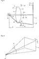
Die erfindungsgemäße Anzeigevorrichtung
Das Vorderteil
Da das Vorderteil
Zur Bilderzeugung kann die erfindungsgemäße Anzeigevorrichtung ein tragbares Bildmodul
In
Die Steuereinheit
Die Sensoreinheit
Das tragbare Gerät
Wie aus der Darstellung in
Dazu ist eine Anwendung bzw. ein Programm auf dem tragbaren Gerät
Da die Anwendung auf dem Gerät
Die beiden Abschnitte
Die Anwendung kann die Bilder
Bei dem tragbaren Gerät
Die einfachste Eingabe ist somit ein einzelnes Antippen, was beispielsweise dem Anklicken einer Schaltfläche mit einer Maus bei einem herkömmlichen Computer entspricht.The simplest input is thus a single tap, which, for example, corresponds to clicking a button with a mouse in a conventional computer.
Die Steuereinheit
Das Antippen des Vorderteils
Trägt beispielsweise ein aufrechtstehender Nutzer mit erhobenem Kopf das Gerät, so bewirkt beispielsweise ein Antippen der linken Seite ein beispielsweise positives Signal im Horizontalsensor, während ein Antippen der rechten Seite ein dann beispielsweises negatives Signal im Horizontalsensor bewirkt. Dagegen zeigt der Vertikalsensor kein Signal.For example, carries an upright user with his head raised the device, for example, causes a tapping the left side, for example, a positive signal in the horizontal sensor, while tapping the right side then causes an example negative signal in the horizontal sensor. In contrast, the vertical sensor shows no signal.
Ein Antippen der rechten oberen Ecke in Richtung links unten bewirkt beispielsweise ein negatives Signal im Horizontalsensor und ein beispielsweises negatives Signal im Vertikalsensor. Ein Antippen der rechten unteren Ecke in Richtung links oben bewirkt dann ein beispielsweise negatives Signal im Horizontalsensor aber ein beispielsweise positives Signal im Vertikalsensor. Und so weiter. Auf diese Art und Weise lässt sich die Richtung des Antippens bestimmen. Da die Form des Vorderteils
Auch ist es möglich, die bestimmte Richtung des Antippens, also die Richtung, in der beim Antippen gegen das Vorderteil
Um eine klare Zuordnung von beispielsweise Menüpunkten oder anderen Funktionalitäten zu erreichen, ist es besonders vorteilhaft – anders als in üblichen Applikationen/Programmen – die Menüpunkte in die Ecken der Bildschirmanzeige zu verlegen, da hier eine klare Zuordnung der Signale zu den entsprechenden Richtungen bzw. angetippten Stellen besonders einfach ist.In order to achieve a clear assignment of, for example, menu items or other functionalities, it is particularly advantageous - unlike in conventional applications / programs - to move the menu items in the corners of the screen, since a clear assignment of the signals to the corresponding directions or tapped It is especially easy to do this.
Durch das Antippen oder Anstoßen des Vorderteils
Die erfindungsgemäße Anzeigevorrichtung stellt somit eine einfach zu bedienende und gut funktionierende Eingabeschnittstelle bereit, mit der das Gerät
Die beiden Abbildungsoptiken
Die erste Abbildungsoptik
Die erste Linse
Die beiden Grenzflächen
Die Asphärenkonstanten für die Flächen
Die Abstände entlang der optischen Achse OA sind in der nachfolgenden Tabelle 2 angegeben. Tabelle 2
Die erste Linse
Die erste Abbildungsoptik
Durch die Ausbildung der beiden Grenzflächen als asphärische Flächen ist es möglich, sphärische Aberrationen und Aberrationen höherer Ordnung zu korrigieren.By forming the two interfaces as aspherical surfaces, it is possible to correct spherical aberrations and higher order aberrations.
Ferner ist die erste Abbildungsoptik
Dabei sind die Winkel β1, β2 und β3 der der Austrittspupille
Dabei bezeichnet K1 die Brennweite, K2 das Verhältnis der Scheitelkrümmung der ersten Grenzfläche
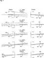
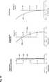
In
In
Mit der ersten Linse
Das virtuelle Bild wird dem Benutzer mit einem Sichtfeld S mit α1 = 85° in diagonaler Richtung (
Da der Abstand zwischen der Austrittspupille
Bei der erfindungsgemäßen Anzeigevorrichtung sind die beiden Abbildungsoptiken
Wie in
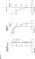
In
Die Abstände entlang der optischen Achse OA für der zweiten Ausführungsform sind in der nachfolgenden Tabelle 5 angegeben. Tabelle 5
Der Wert für BGL sowie für weitere die erste Abbildungsoptik
In
Die Abstände entlang der optischen Achse OA der dritten Ausführungsform sind in der nachfolgenden Tabelle 8 angegeben. Tabelle 8
Der Wert für BGL sowie für weitere die erste Abbildungsoptik
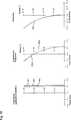
In
Die Abstände entlang der optischen Achse OA der vierten Ausführungsform sind in der nachfolgenden Tabelle 11 angegeben. Tabelle 11
Der Wert für BGL sowie für weitere die erste Abbildungsoptik
In
Die Abstände entlang der optischen Achse OA der fünften Ausführungsform sind in der nachfolgenden Tabelle 14 angegeben. Tabelle 14
Der Wert für BGL sowie für weitere die erste Abbildungsoptik
In
Die Abstände entlang der optischen Achse OA der sechsten Ausführungsform sind in der nachfolgenden Tabelle 17 angegeben. Tabelle 17
Der Wert für BGL sowie für weitere die erste Abbildungsoptik
In
Die Abstände entlang der optischen Achse OA der siebten Ausführungsform sind in der nachfolgenden Tabelle 20 angegeben. Tabelle 20
Der Wert für BGL sowie für weitere die erste Abbildungsoptik
In
Die Abstände entlang der optischen Achse OA der achten Ausführungsform sind in der nachfolgenden Tabelle 23 angegeben. Tabelle 23
Der Wert für BGL sowie für weitere die erste Abbildungsoptik
Claims (12)
Translated fromGermanPriority Applications (4)
| Application Number | Priority Date | Filing Date | Title |
|---|---|---|---|
| DE102014017534.0ADE102014017534A1 (en) | 2014-11-24 | 2014-11-24 | Display device which can be placed on the head of a user |
| PCT/EP2015/075882WO2016083095A1 (en) | 2014-11-24 | 2015-11-06 | Display device which can be placed on the head of a user |
| CN201580061628.5ACN107003504A (en) | 2014-11-24 | 2015-11-06 | The display device on user's head can be worn over |
| US15/529,083US20170343819A1 (en) | 2014-11-24 | 2015-11-24 | Display device which can be placed on the head of a user |
Applications Claiming Priority (1)
| Application Number | Priority Date | Filing Date | Title |
|---|---|---|---|
| DE102014017534.0ADE102014017534A1 (en) | 2014-11-24 | 2014-11-24 | Display device which can be placed on the head of a user |
Publications (1)
| Publication Number | Publication Date |
|---|---|
| DE102014017534A1true DE102014017534A1 (en) | 2016-05-25 |
Family
ID=54478751
Family Applications (1)
| Application Number | Title | Priority Date | Filing Date |
|---|---|---|---|
| DE102014017534.0AWithdrawnDE102014017534A1 (en) | 2014-11-24 | 2014-11-24 | Display device which can be placed on the head of a user |
Country Status (4)
| Country | Link |
|---|---|
| US (1) | US20170343819A1 (en) |
| CN (1) | CN107003504A (en) |
| DE (1) | DE102014017534A1 (en) |
| WO (1) | WO2016083095A1 (en) |
Cited By (3)
| Publication number | Priority date | Publication date | Assignee | Title |
|---|---|---|---|---|
| CN107238930A (en)* | 2017-07-19 | 2017-10-10 | 北京小米移动软件有限公司 | Virtual reality glasses |
| DE102016218582A1 (en) | 2016-09-27 | 2018-03-29 | Bayerische Motoren Werke Aktiengesellschaft | Projection display device with a display in several display levels |
| US10292581B2 (en) | 2014-09-22 | 2019-05-21 | Carl Zeiss Vision International Gmbh | Display device for demonstrating optical properties of eyeglasses |
Families Citing this family (2)
| Publication number | Priority date | Publication date | Assignee | Title |
|---|---|---|---|---|
| CN107275904B (en)* | 2017-07-19 | 2024-05-24 | 北京小米移动软件有限公司 | Data cable for virtual reality glasses |
| CN108333748B (en)* | 2018-02-24 | 2021-01-26 | 京东方科技集团股份有限公司 | Lens optimization method and device for virtual reality equipment |
Family Cites Families (6)
| Publication number | Priority date | Publication date | Assignee | Title |
|---|---|---|---|---|
| GB643938A (en)* | 1948-06-01 | 1950-09-27 | Christian Ellis Coulman | Lenses |
| GB2200763B (en)* | 1987-01-28 | 1991-02-13 | Combined Optical Ind Ltd | Stand magnifiers and lens |
| JP2005062803A (en)* | 2003-07-31 | 2005-03-10 | Olympus Corp | Imaging optical system and optical device using the same |
| US8957835B2 (en)* | 2008-09-30 | 2015-02-17 | Apple Inc. | Head-mounted display apparatus for retaining a portable electronic device with display |
| US8767305B2 (en)* | 2011-08-02 | 2014-07-01 | Google Inc. | Method and apparatus for a near-to-eye display |
| GB2499102B (en)* | 2013-01-11 | 2013-12-25 | Mvr Global Ltd | Head-mounted display device |
- 2014
- 2014-11-24DEDE102014017534.0Apatent/DE102014017534A1/ennot_activeWithdrawn
- 2015
- 2015-11-06CNCN201580061628.5Apatent/CN107003504A/enactivePending
- 2015-11-06WOPCT/EP2015/075882patent/WO2016083095A1/enactiveApplication Filing
- 2015-11-24USUS15/529,083patent/US20170343819A1/ennot_activeAbandoned
Cited By (6)
| Publication number | Priority date | Publication date | Assignee | Title |
|---|---|---|---|---|
| US10292581B2 (en) | 2014-09-22 | 2019-05-21 | Carl Zeiss Vision International Gmbh | Display device for demonstrating optical properties of eyeglasses |
| DE102016218582A1 (en) | 2016-09-27 | 2018-03-29 | Bayerische Motoren Werke Aktiengesellschaft | Projection display device with a display in several display levels |
| CN107238930A (en)* | 2017-07-19 | 2017-10-10 | 北京小米移动软件有限公司 | Virtual reality glasses |
| EP3432052A3 (en)* | 2017-07-19 | 2019-05-29 | Beijing Xiaomi Mobile Software Co., Ltd. | Virtual reality glasses |
| US10580383B2 (en) | 2017-07-19 | 2020-03-03 | Beijing Xiaomi Mobile Software Co., Ltd. | Virtual reality glasses |
| EP3855237A3 (en)* | 2017-07-19 | 2021-10-20 | Beijing Xiaomi Mobile Software Co., Ltd. | Virtual reality glasses |
Also Published As
| Publication number | Publication date |
|---|---|
| US20170343819A1 (en) | 2017-11-30 |
| WO2016083095A1 (en) | 2016-06-02 |
| CN107003504A (en) | 2017-08-01 |
Similar Documents
| Publication | Publication Date | Title |
|---|---|---|
| EP3956721B1 (en) | Determination of at least one optical parameter of a spectacle lens | |
| DE69113287T2 (en) | Display device in the form of glasses for direct display on the retina. | |
| EP3189372A1 (en) | Display device for demonstrating optical properties of eyeglasses | |
| DE102014207499A1 (en) | Spectacle lens for a display device that can be placed on the head of a user and forms an image | |
| DE102015116297A1 (en) | Imaging optics and display device with such imaging optics | |
| EP3293558B1 (en) | Device for recording a stereo image | |
| DE112019003514T5 (en) | EYEPIECE AND DISPLAY DEVICE | |
| WO2016083095A1 (en) | Display device which can be placed on the head of a user | |
| DE102015001874A1 (en) | Device and method for distance determination and / or centering using corneal reflections | |
| DE102015219859B4 (en) | Apparatus and method for AR display | |
| DE102014119550A1 (en) | Imaging optics for generating a virtual image and data glasses | |
| DE102017125731A1 (en) | Optical fiber, imaging device and HMD with separate imaging channels | |
| DE102014107938B4 (en) | Display device | |
| DE102018105917A1 (en) | A method for user-specific calibration of a superimposed on the head of a user display device for an augmented presentation | |
| WO2013104353A1 (en) | Mobile video centring system for determining centring data for spectacle lenses | |
| DE102014013447A1 (en) | Method for the accurate determination of optical parameters of a subject for the adaptation of glasses to the subject and immobiles Videozentriersystem | |
| EP4185920B1 (en) | Computer-implemented method for generating data for producing at least one spectacle lens and method for manufacturing spectacles | |
| DE102014113685A1 (en) | Display device which can be placed on the head of a user, and methods for controlling such a display device | |
| WO2011131169A1 (en) | Video centering system having visual-field evaluation and method for evaluating visual fields | |
| DE102014113686A1 (en) | Display device which can be placed on the head of a user, and methods for controlling such a display device | |
| WO2015158830A1 (en) | Display device and display method | |
| DE102007046505B4 (en) | Display device and stereo display module | |
| DE102017114502B3 (en) | mirror device | |
| WO2022034231A2 (en) | Optical system | |
| EP3192433A1 (en) | Mobile video centring system for the determination of centring data for spectacle lenses |
Legal Events
| Date | Code | Title | Description |
|---|---|---|---|
| R119 | Application deemed withdrawn, or ip right lapsed, due to non-payment of renewal fee |