DE102014013724A1 - Method for staking boreholes of a vehicle - Google Patents
Method for staking boreholes of a vehicleDownload PDFInfo
- Publication number
- DE102014013724A1 DE102014013724A1DE102014013724.4ADE102014013724ADE102014013724A1DE 102014013724 A1DE102014013724 A1DE 102014013724A1DE 102014013724 ADE102014013724 ADE 102014013724ADE 102014013724 A1DE102014013724 A1DE 102014013724A1
- Authority
- DE
- Germany
- Prior art keywords
- vehicle
- boreholes
- points
- design data
- measured
- Prior art date
- Legal status (The legal status is an assumption and is not a legal conclusion. Google has not performed a legal analysis and makes no representation as to the accuracy of the status listed.)
- Withdrawn
Links
- 238000000034methodMethods0.000titleclaimsabstractdescription47
- 239000000523sampleSubstances0.000claimsabstractdescription30
- 238000013461designMethods0.000claimsabstractdescription25
- 238000010276constructionMethods0.000claimsabstractdescription3
- 238000005259measurementMethods0.000claimsdescription18
- 238000005553drillingMethods0.000claimsdescription8
- 238000004519manufacturing processMethods0.000description8
- 230000000712assemblyEffects0.000description2
- 238000000429assemblyMethods0.000description2
- 238000007796conventional methodMethods0.000description2
- BUHVIAUBTBOHAG-FOYDDCNASA-N(2r,3r,4s,5r)-2-[6-[[2-(3,5-dimethoxyphenyl)-2-(2-methylphenyl)ethyl]amino]purin-9-yl]-5-(hydroxymethyl)oxolane-3,4-diolChemical compoundCOC1=CC(OC)=CC(C(CNC=2C=3N=CN(C=3N=CN=2)[C@H]2[C@@H]([C@H](O)[C@@H](CO)O2)O)C=2C(=CC=CC=2)C)=C1BUHVIAUBTBOHAG-FOYDDCNASA-N0.000description1
- 238000004026adhesive bondingMethods0.000description1
- 230000008878couplingEffects0.000description1
- 238000010168coupling processMethods0.000description1
- 238000005859coupling reactionMethods0.000description1
- 238000013499data modelMethods0.000description1
- 230000001419dependent effectEffects0.000description1
- 238000012938design processMethods0.000description1
- 238000001514detection methodMethods0.000description1
- 230000002452interceptive effectEffects0.000description1
- 239000003550markerSubstances0.000description1
- 238000013208measuring procedureMethods0.000description1
- 238000012545processingMethods0.000description1
- 238000000275quality assuranceMethods0.000description1
- 230000003068static effectEffects0.000description1
- 238000003860storageMethods0.000description1
Images
Classifications
- G—PHYSICS
- G01—MEASURING; TESTING
- G01B—MEASURING LENGTH, THICKNESS OR SIMILAR LINEAR DIMENSIONS; MEASURING ANGLES; MEASURING AREAS; MEASURING IRREGULARITIES OF SURFACES OR CONTOURS
- G01B11/00—Measuring arrangements characterised by the use of optical techniques
- G01B11/002—Measuring arrangements characterised by the use of optical techniques for measuring two or more coordinates
- G—PHYSICS
- G01—MEASURING; TESTING
- G01B—MEASURING LENGTH, THICKNESS OR SIMILAR LINEAR DIMENSIONS; MEASURING ANGLES; MEASURING AREAS; MEASURING IRREGULARITIES OF SURFACES OR CONTOURS
- G01B5/00—Measuring arrangements characterised by the use of mechanical techniques
- G01B5/004—Measuring arrangements characterised by the use of mechanical techniques for measuring coordinates of points
- G—PHYSICS
- G01—MEASURING; TESTING
- G01S—RADIO DIRECTION-FINDING; RADIO NAVIGATION; DETERMINING DISTANCE OR VELOCITY BY USE OF RADIO WAVES; LOCATING OR PRESENCE-DETECTING BY USE OF THE REFLECTION OR RERADIATION OF RADIO WAVES; ANALOGOUS ARRANGEMENTS USING OTHER WAVES
- G01S17/00—Systems using the reflection or reradiation of electromagnetic waves other than radio waves, e.g. lidar systems
- G01S17/02—Systems using the reflection of electromagnetic waves other than radio waves
- G01S17/06—Systems determining position data of a target
- G01S17/42—Simultaneous measurement of distance and other co-ordinates
- G—PHYSICS
- G01—MEASURING; TESTING
- G01S—RADIO DIRECTION-FINDING; RADIO NAVIGATION; DETERMINING DISTANCE OR VELOCITY BY USE OF RADIO WAVES; LOCATING OR PRESENCE-DETECTING BY USE OF THE REFLECTION OR RERADIATION OF RADIO WAVES; ANALOGOUS ARRANGEMENTS USING OTHER WAVES
- G01S17/00—Systems using the reflection or reradiation of electromagnetic waves other than radio waves, e.g. lidar systems
- G01S17/02—Systems using the reflection of electromagnetic waves other than radio waves
- G01S17/06—Systems determining position data of a target
- G01S17/46—Indirect determination of position data
- G—PHYSICS
- G01—MEASURING; TESTING
- G01S—RADIO DIRECTION-FINDING; RADIO NAVIGATION; DETERMINING DISTANCE OR VELOCITY BY USE OF RADIO WAVES; LOCATING OR PRESENCE-DETECTING BY USE OF THE REFLECTION OR RERADIATION OF RADIO WAVES; ANALOGOUS ARRANGEMENTS USING OTHER WAVES
- G01S17/00—Systems using the reflection or reradiation of electromagnetic waves other than radio waves, e.g. lidar systems
- G01S17/66—Tracking systems using electromagnetic waves other than radio waves
- G—PHYSICS
- G01—MEASURING; TESTING
- G01S—RADIO DIRECTION-FINDING; RADIO NAVIGATION; DETERMINING DISTANCE OR VELOCITY BY USE OF RADIO WAVES; LOCATING OR PRESENCE-DETECTING BY USE OF THE REFLECTION OR RERADIATION OF RADIO WAVES; ANALOGOUS ARRANGEMENTS USING OTHER WAVES
- G01S17/00—Systems using the reflection or reradiation of electromagnetic waves other than radio waves, e.g. lidar systems
- G01S17/88—Lidar systems specially adapted for specific applications
- G01S17/89—Lidar systems specially adapted for specific applications for mapping or imaging
- G—PHYSICS
- G01—MEASURING; TESTING
- G01S—RADIO DIRECTION-FINDING; RADIO NAVIGATION; DETERMINING DISTANCE OR VELOCITY BY USE OF RADIO WAVES; LOCATING OR PRESENCE-DETECTING BY USE OF THE REFLECTION OR RERADIATION OF RADIO WAVES; ANALOGOUS ARRANGEMENTS USING OTHER WAVES
- G01S7/00—Details of systems according to groups G01S13/00, G01S15/00, G01S17/00
- G01S7/48—Details of systems according to groups G01S13/00, G01S15/00, G01S17/00 of systems according to group G01S17/00
- G01S7/481—Constructional features, e.g. arrangements of optical elements
- G—PHYSICS
- G01—MEASURING; TESTING
- G01S—RADIO DIRECTION-FINDING; RADIO NAVIGATION; DETERMINING DISTANCE OR VELOCITY BY USE OF RADIO WAVES; LOCATING OR PRESENCE-DETECTING BY USE OF THE REFLECTION OR RERADIATION OF RADIO WAVES; ANALOGOUS ARRANGEMENTS USING OTHER WAVES
- G01S7/00—Details of systems according to groups G01S13/00, G01S15/00, G01S17/00
- G01S7/48—Details of systems according to groups G01S13/00, G01S15/00, G01S17/00 of systems according to group G01S17/00
- G01S7/51—Display arrangements
Landscapes
- Physics & Mathematics (AREA)
- Engineering & Computer Science (AREA)
- General Physics & Mathematics (AREA)
- Electromagnetism (AREA)
- Computer Networks & Wireless Communication (AREA)
- Radar, Positioning & Navigation (AREA)
- Remote Sensing (AREA)
- Length Measuring Devices With Unspecified Measuring Means (AREA)
Abstract
Translated fromGermanDescription
Translated fromGermanDie vorliegende Erfindung betrifft ein Verfahren zum Abstecken von Bohrlöchern eines Fahrzeugs mit hoher Genauigkeit.The present invention relates to a method for staking boreholes of a vehicle with high accuracy.
Aus
Aus
Aus
Beim herkömmlichen Verfahren zum Abstecken von Bohrlöchern im Fahrzeugbau wird mit Schablonen gearbeitet. Im Innenraum beispielsweise eines Waggons werden dazu etwa 1500 Befestigungspunkte angebracht. Bohrlöcher werden im Wageninneren angebracht damit im Innenraum Einrichtungen aufgehängt werden können. Das ergibt sich aus der Konstruktionszeichnung. Dafür müssen passende Schablonen gefertigt werden. Die Positionierung der Schablonen wird ermittelt. Der Abstand zum Rand, daher zu der oberen und unteren Kante im Fensterabschnitt wird gemessen. Dann wird die Schablone angesetzt. Die Schablonen müssen gefertigt und verwaltet werden. Bei geänderten Wagen müssen die Schablonen neu hergestellt werden.In the conventional method for staking boreholes in vehicle construction is used with templates. In the interior, for example, a wagon to about 1500 attachment points are attached. Drill holes are placed inside the car so that equipment can be hung in the interior. This results from the design drawing. For this, suitable templates must be made. The positioning of the templates is determined. The distance to the edge, therefore to the upper and lower edge in the window section is measured. Then the template is attached. The templates must be manufactured and managed. If the car has changed, the templates must be rebuilt.
Die Aufgabe der vorliegenden Erfindung ist es, ein schnelles, kostengünstiges, zuverlässiges und umweltfreundliches Verfahren zum Abstecken von Bohrlöchern mit hoher Genauigkeit und Zuverlässigkeit bereitzustellen.The object of the present invention is to provide a fast, inexpensive, reliable and environmentally friendly method of staking wells with high accuracy and reliability.
Die Aufgabe wird durch ein erfindungsgemäßes Verfahren zum Abstecken von Bohrlöchern eines Fahrzeugs nach Patentanspruch 1 gelöst.The object is achieved by an inventive method for staking boreholes of a vehicle according to
Das erfindungsgemäße Verfahren eines Fahrzeugs enthält die folgenden Verfahrensschritte.
- – Konstruktionsdaten des Fahrzeugs werden gespeichert und Messpunkte und Bohrlöcher werden aus den Konstruktionsdaten extrahiert.
- – Messpunkte des Fahrzeugs werden auf den Seitenwänden, den Stirnwänden und dem Boden gemessen.
- – Die Messpunkte werden aus den Konstruktionsdaten mit den gemessenen Messpunkten abgeglichen.
- – Bohrlöchern werden aus den Konstruktionsdaten gemessene 3D-Koordinaten (x, y, z) zugewiesen.
- – Die Markierung der Bohrlöcher erfolgt über einen Taster. Dazu wird der Taster an eine nach Konstruktionsdaten angezeigte 3D-Koordinate herangeführt und die 3D-Koordinaten werden in derselben Farbe angezeigt, wenn sich der Taster innerhalb vorgegebener Toleranzen befindet.
- - Vehicle design data is stored and measurement points and drill holes are extracted from the design data.
- - Measuring points of the vehicle are measured on the side walls, the end walls and the ground.
- - The measuring points are compared with the measured measuring points from the design data.
- - Drilling holes are assigned 3D coordinates (x, y, z) measured from the design data.
- - The holes are marked by a push-button. For this purpose, the button is brought to a 3D coordinate displayed according to design data and the 3D coordinates are displayed in the same color when the button is within specified tolerances.
Das erfindungsgemäße Verfahren zum Abstecken von Bohrlöchern ist gekennzeichnet durch folgende Verfahrensschritte:
- – Die Konstruktionsdaten werden gesammelt und dokumentiert.
- – Die Konstruktionsdaten werden aufbereitet. Dabei werden die Konstruktionsdaten bereinigt. Das heißt die Messpunkte, Bohrlöcher oder weitere, den Anforderungen entsprechende Informationen werden aus den Konstruktionsdaten extrahiert.
- – Die Vermessung erfolgt vor Ort. Flexible Messgeräte werden positioniert, Flächen und Referenzpunkte werden gescannt. Der Mess- oder Scanvorgang beginnt. Der Abgleich von virtuellem und realem Raum erfolgt durch den Orientierungsprozess mittels Reflektorkugeln im Wagenkasten.
- – Die sich anschließende Qualitätssicherung wird dokumentiert. Flexible Positionierungen der Messgeräte erlauben das Scannen von Flächen und Referenzpunkten fast überall, wie bei Gebäuden, Brücken, Maschinen und in Fahrzeugen, Schiffen und Flugzeugen.
- - The design data is collected and documented.
- - The design data is processed. The design data is cleaned up. That is, the measurement points, drill holes, or other information corresponding to the requirements are extracted from the design data.
- - The survey is done on site. Flexible measuring devices are positioned, areas and reference points are scanned. The measuring or scanning process begins. The comparison of virtual and real space takes place through the orientation process using reflector balls in the car body.
- - The subsequent quality assurance is documented. Flexible positioning of the measuring devices allows scanning of surfaces and reference points almost everywhere, such as buildings, bridges, machinery and in vehicles, ships and aircraft.
Für Planungsvorhaben oder zur Erfassung des Ist-Zustandes für Dokumentationszwecke sind oft die Geometrie eines Objektes oder lediglich Ausschnitte davon zu erfassen. Dabei handelt es sich um Einzelpunkte, Linien, Flächen oder Volumen. Ein Beispiel hierfür könnte eine Produktionshalle sein, die durch neue Maschinen oder eine andere Anordnung ergänzt oder optimiert werden soll. Um solche Rationalisierungsprozesse effektiv durchzuführen, müssen exakte Daten über die Position der Objekte im Raum gewonnen werden.For planning projects or to capture the actual state for documentation purposes, the geometry of an object or only sections of it are often to be recorded. These are single points, lines, areas or volumes. An example of this could be a production hall that is to be supplemented or optimized by new machines or another arrangement. To effectively perform such rationalization processes, exact data about the position of the objects in space must be obtained.
Durch das erfindungsgemäße Verfahren werden Schablonen eingespart und die Nachteile, die sich aus der Verwendung von Schablonen ergeben aufgehoben. Die gesamte Bohrschablonen-Logistik entfällt, das heißt die Herstellung der Schablonen, Aufbewahrung und Archivierung und der Transport von Schablonen an den Ort der Vermessung. Das alles entfällt bei der Anwendung des erfindungsgemäßen Verfahrens. Die Zeitersparnis und die Kostenersparnis sind bemerkenswert. Personal kann aufgrund des Wegfalls von Schablonen eingespart werden. Besonders wichtig ist die stark erhöhte Präzision des erfindungsgemäßen Verfahrens. Die Löcher werden zueinander richtig gesetzt. Durch die gleichzeitige automatische Protokollierung werden die Messergebnisse für eine Person leicht nachvollziehbar. Das erfindungsgemäße Verfahren ermöglicht einen sauberen Produktionsprozess. Durch die hohe Maßhaltigkeit entfällt die Nacharbeit und das bedeutet hohe Produktqualität.Stencils are saved by the method according to the invention and the disadvantages arising from the use of templates are eliminated. The entire surgical template logistics is eliminated, ie the production of the templates, storage and archiving and the transport of templates to the site of the survey. All this is eliminated when using the method according to the invention. The time savings and the cost savings are remarkable. Staff can be saved due to the omission of templates. Particularly important is the greatly increased precision of the method according to the invention. The holes are set correctly to each other. Simultaneous automatic logging makes the measurement results easily comprehensible for one person. The method according to the invention enables a clean production process. The high dimensional accuracy eliminates the rework and this means high product quality.
Das erfindungsgemäße Verfahren eignet sich insbesondere dazu, Bohrlöcher in Fahrzeugen abzustecken und diese so auf die weitere Fertigung vorzubereiten. Mit dem erfindungsgemäßen Verfahren wird das herkömmliche Verfahren der Bohrschablonennutzung abgelöst und der Fertigungsprozess gestrafft und optimiert. Dabei hat sich gezeigt, dass das erfindungsgemäße Verfahren über eine dauerhafte Verfügbarkeit der Dienstleistung auch an mehreren Einsatzorten sowie eine hohe zeitliche Flexibilität verfügt, um Leistungsspitzen jederzeit vermessungstechnisch begleiten zu können.The method according to the invention is particularly suitable for staking out boreholes in vehicles and thus preparing them for further production. With the method according to the invention, the conventional method of Bohrschablone use is replaced and the manufacturing process streamlined and optimized. It has been shown that the method according to the invention has a permanent availability of the service even at several locations and a high flexibility of time in order to be able to accompany performance peaks at any time with regard to surveying.
Nach einer vorteilhaften Ausgestaltung der vorliegenden Erfindung werden Konstruktionsdaten eines Fahrzeugs als CAD-Daten unter Nutzung insbesondere von CATIA aufbereitet. In einem ersten Schritt werden CAD-Daten unter Nutzung von CATIA aufbereitet und Punktdateien mit den dreidimensionalen Koordinaten der Bohrpunkte exportiert. CATIA (Computer Aided Three-Dimensional Interactive Application) ist ein CAD-Programm. Der Konstruktionsprozess umfasst in CATIA die Erstellung dreidimensionaler Modelle sowie die Ableitung dazugehöriger zweidimensionaler Zeichnungen. Ebenso werden im weiteren Projektverlauf vorgenommene Änderungen am Konstruktionsmodell in das Datenmodell eingepflegt und für die weiteren Prozessschritte aufbereitet.According to an advantageous embodiment of the present invention, design data of a vehicle are processed as CAD data using, in particular, CATIA. In a first step, CAD data is processed using CATIA and point files are exported with the three-dimensional coordinates of the drilling points. CATIA (Computer Aided Three-Dimensional Interactive Application) is a CAD program. The design process in CATIA involves creating three-dimensional models and deriving related two-dimensional drawings. Likewise, changes made to the design model during the course of the project will be incorporated into the data model and processed for the further process steps.
Für die eigentliche Absteckung der Bohrlöcher ist zuerst eine Orientierung des Messsystems im Rohbauwagenkasten erforderlich. Anschließend werden beispielsweise die für den Innenausbau relevanten Bohrlöcher mit der gewünschten Punktgenauigkeit von mindestens 0,5 mm unter Berücksichtigung voneinander abhängiger Baugruppenelemente angerissen. Abschließend erfolgt die Kontrolle aller abgesteckten Punkte. Die dreidimensionalen Koordinaten aller angerissenen Punkte werden in Sicherungsdateien protokolliert und archiviert. Das Messverfahren verkürzt die Absteckung von Bohrpunkten. Im Rohbau werden aus dem CAD-Modell die Positionen übertragen und es kann zeitgleich gekörnt werden.For the actual stakeout of the drill holes, an orientation of the measuring system in the body shop box is first required. Subsequently, for example, the relevant holes for the interior work are torn with the desired accuracy of at least 0.5 mm, taking into account mutually dependent assembly elements. Finally, the control of all staked points. The three-dimensional coordinates of all scribed points are logged and archived in backup files. The measuring method shortens the stakeout of drilling points. In the bodyshell, the positions are transferred from the CAD model and it can be grained at the same time.
Nach einer vorteilhaften Ausgestaltung der vorliegenden Erfindung werden am Fahrzeug jeweils 6 bis 12, bevorzugt 8 bis 10 Messpunkte auf den Seitenwänden, den Stirnwänden und dem Boden mit einem mobilen Lasertracker gemessen werden. Mit dieser Zahl der Messpunkte wird ein gutes Ergebnis erzielt.According to an advantageous embodiment of the present invention, in each case 6 to 12, preferably 8 to 10 measuring points on the side walls, the end walls and the floor are measured with a mobile laser tracker. With this number of measuring points a good result is achieved.
Nach einer vorteilhaften Ausgestaltung der vorliegenden Erfindung erfolgt der Abgleich von virtuellem und realem Raum durch den Abgleich von Orientierungsprozess mittels Reflektorkugeln im Wagenkasten.According to an advantageous embodiment of the present invention, the alignment of virtual and real space is carried out by the adjustment of orientation process by means of reflector balls in the car body.
Nach einer weiteren vorteilhaften Ausgestaltung der vorliegenden Erfindung besteht die Referenzbasis aus mindestens drei Reflektorkugeln. Sie wird fest an einem Fixpunkt montiert und bildet den Ursprung des aufgespannten Koordinatensystems. Der Referenzarm ist hier der Laserstrahl. Über die Variation der Länge des Referenzarms, daher Laufzeiten der Funksignale der Laserstrahlen werden mittels einer präzisen Linearachse an jeder Raumposition die drei Abstände des Messpunktes zu den drei Reflektorkugeln ermittelt.According to a further advantageous embodiment of the present invention, the reference base consists of at least three reflector balls. It is permanently mounted on a fixed point and forms the origin of the clamped coordinate system. The reference arm here is the laser beam. By varying the length of the reference arm, therefore running times of the radio signals of the laser beams are determined by means of a precise linear axis at each spatial position, the three distances of the measuring point to the three reflector balls.
Nach einer vorteilhaften Ausgestaltung der vorliegenden Erfindung werden anzubringenden Bohrlöchern aus den Konstruktionsdaten gemessene 3D-Koordinaten (x, y, z) zugewiesen, indem an jeder Raumposition die drei Abstände des Messpunktes zu den drei Reflektorkugeln ermittelt werden und die Position des Bohrloches daraus mittels einer Trilateration bestimmt wird. Trilateration ist ein Messverfahren zur Positionsbestimmung eines Punktes. Trilateration bedeutet, dass erst die Kenntnis der Entfernung zu drei bekannten Punkten eine eindeutige Bestimmung der Position im Raum ermöglicht. Zwar haben drei Kugelschalen zwei zueinander symmetrische Schnittpunkte, doch einer davon lässt sich meist durch Plausibilitätsüberlegungen ausschließen.According to an advantageous embodiment of the present invention, boreholes are assigned 3D coordinates (x, y, z) measured from the design data by determining the three distances of the measuring point to the three reflector spheres at each spatial position and the position of the borehole therefrom by means of a trilateration is determined. Trilateration is a Measuring method for determining the position of a point. Trilateration means that only the knowledge of the distance to three known points allows a clear determination of the position in space. Although three spherical shells have two mutually symmetrical intersections, one of them can usually be ruled out by plausibility considerations.
Der Vorteil dieses Messverfahrens liegt in der freien Positionierbarkeit des Messvolumens. Des Weiteren stören kurze Strahlunterbrechungen eine Messung oder Messreihe nicht, da die eigentliche Messung der Reflexionssignale im Millisekundenbereich und jede Positionsbestimmung unabhängig und absolut erfolgt. Wenn für die Messungen herkömmliche Messnormale verwendet werden, kann die Einrichtung oder Neuausrichtung von Maschinen mehrere Tage dauern. Mit dem erfindungsgemäßen Verfahren zur exakten und automatisierbaren Bestimmung von Raumkoordinaten, von Abständen und Winkeln wird diese Messzeit auf einige Stunden verkürzt.The advantage of this measuring method lies in the free positioning of the measuring volume. Furthermore, short beam interruptions do not interfere with a measurement or measurement series, since the actual measurement of the reflection signals in the millisecond range and each position determination takes place independently and absolutely. If conventional measurement standards are used for the measurements, the setup or realignment of machines can take several days. With the method according to the invention for the exact and automatable determination of spatial coordinates, distances and angles, this measurement time is shortened to a few hours.
Nach einer vorteilhaften Ausgestaltung der vorliegenden Erfindung erfolgt die Markierung der anzubringenden Bohrlöcher über eine kabellose T-Probe. Nach einer besonders vorteilhaften Ausgestaltung der vorliegenden Erfindung werden die 3D-Koordinaten farblich rot angezeigt und wenn die kabellose T-Probe innerhalb vorgegebener Toleranzen einer 3D-Koordinate geführt wird, dann wird die 3D-Koordinate grün angezeigt und wenn die T-Probe so geführt wird, dass alle drei 3D-Koortinaten grün angezeigt werden, dann ist die T-Probe innerhalb der vorgegebenen Toleranzen. Dann kann die Markierung des anzubringenden Bohrlochs vorgenommen werden.According to an advantageous embodiment of the present invention, the marking of the drill holes to be attached via a wireless T-probe. According to a particularly advantageous embodiment of the present invention, the 3D coordinates are displayed in color red and when the wireless T-sample is guided within predetermined tolerances of a 3D coordinate, then the 3D coordinate is displayed in green and when the T-sample is guided in that all three 3D co-ordinates are displayed in green, then the T-sample is within the given tolerances. Then the marking of the borehole to be attached can be made.
Nach einer vorteilhaften Ausgestaltung der vorliegenden Erfindung erfolgt gleichzeitig mit der Markierung des anzubringenden Bohrlochs die Körnung des Bohrlochs. Die direkte Kopplung von Messprozess und Körnung ist schnell und präzise.According to an advantageous embodiment of the present invention, the grain of the borehole is carried out simultaneously with the marking of the borehole to be mounted. The direct coupling of measurement process and grain size is fast and precise.
Die vorliegende Erfindung wird weiter gelöst durch die Verwendung eines Lasertrackers für das erfindungsgemäße Verfahren zum Abstecken von Bohrlöchern. Der Lasertracker enthält einen Absolutdistanzmesser (ADM), einen Interferometer (IFM), eine positionsempfindliche Diode (PSD), einen Winkelencoder und einen Reflektor in Verbindung mit einer kabellosen T-Probe zum Abstecken von anzubringenden Befestigungspunkten bei Gebäuden, Brücken, Maschinen und in Fahrzeugen, Schiffen und Flugzeugen.The present invention is further solved by the use of a laser tracker for the method according to the invention for staking out wells. The laser tracker includes an absolute distance meter (ADM), an interferometer (IFM), a position sensitive diode (PSD), an angle encoder and a reflector in conjunction with a wireless T-probe for stake out mounting points on buildings, bridges, machinery and in vehicles, Ships and planes.
Mit einem Lasertracker wird ein Ziel automatisch erfasst, sobald es im Sichtfeld des Sensors liegt. Der Lasertracker verfügt über sechs Freiheitsgraden. Bei dem Lasertracker, zum Beispiel Leica AT901-MR handelt es sich um ein mobiles Messsystem, welches vorzugsweise in der Präzisionsindustrie zum Einsatz kommt. Innerhalb des typischen Messvolumens von bis zu 18 m können mithilfe eines Laserstrahls präzise Messungen vorgenommen werden.A laser tracker automatically detects a target as soon as it is within the field of view of the sensor. The laser tracker has six degrees of freedom. The laser tracker, for example the Leica AT901-MR, is a mobile measuring system, which is preferably used in the precision industry. Within the typical measuring volume of up to 18 m, precise measurements can be made with the help of a laser beam.
Das Interferometer (IFM) ist in der Lage, die absolute Distanz zu einem Reflektor zu messen. Das Gerät kann demnach einen unterbrochenen Laserstrahl gleich wiederherstellen und sofort das bewegliche Ziel messen. Mehrere eingebaute Redundanzsysteme sollen für zuverlässige Messdaten sorgen. Das neue IFM misst absolute Distanzen zu einem Ziel.The interferometer (IFM) is able to measure the absolute distance to a reflector. The device can thus immediately restore an interrupted laser beam and immediately measure the moving target. Several built-in redundancy systems should provide reliable measurement data. The new IFM measures absolute distances to a destination.
Das leichte Design und die kompakten Abmessungen des Lasertrackers ermöglichen den Transport und Aufbau des Messgeräts durch nur eine Person, sodass der Lasertracker ortsungebunden und flexibel einsetzbar ist. Zusätzlich sorgt eine kurze Initialisierungsphase dafür, dass der Lasertracker schnelle Einsatzbereitschaft.The lightweight design and compact dimensions of the laser tracker allow the device to be transported and set up by just one person, making the laser tracker portable and flexible. In addition, a short initialization phase ensures that the laser tracker fast deployment.
xxxIn Verbindung mit einem kabellosen Taster (T-Probe) bietet der Laser Scanner ein entsprechendes Arbeitsvolumen. Mithilfe von PowerLock und dem Interferometer (IFM) kann der Lasertracker absolute Distanzen zu einem Ziel mit einem Höchstmaß an Genauigkeit messen, sodass präzise Ergebnisse garantiert werden können. Die T-Probe dient zur Abtastung und Überprüfung verborgener Punkte ohne Einschränkung durch mechanische Arme und Kabel. Dank erhöhter Präzision wird eine zehnfach verbesserte Punktmessrate erreicht. Die kabellose T-Probe dient der tastenden Messung im statischen und dynamischen Messmodus. Erfassen von Punkten im Bereich von Hinterschneidungen und Messen verdeckter Punkte ist damit ebenso möglich wie das Erfassen von Kanten und geometrischen Elementen. Zur Vereinfachung der Handhabung verfügt die T-Probe über zwei im rechten Winkel zueinander angeordnete mechanische Interfaces, die der Aufnahme der variabel zu gestaltenden Tastspitzen dienen und über Statusanzeigen in Form von farbigen LED verfügen. Der Wechsel der einmal kalibrierten Tastspitzen wird automatisch erkannt und dem System direkt mitgeteilt. Die T-Probe verfügt über 6 Freiheitsgrade. Die T-Probe verfügt auch über längere Styli und eine Messweite von bis zu 30 m. Die T-Probe hat einen Nickwinkel: ±45°, Gierwinkel: ±45°, Rollwinkel: ±360°, eine Punktausgaberate bis zu 1.000 Hz und eine Trackinggeschwindigkeit > 1 m/s.xxxIn conjunction with a wireless probe (T-Probe), the laser scanner offers a corresponding working volume. Using PowerLock and the Interferometer (IFM), the laser tracker can measure absolute distances to a target with the highest level of accuracy, so accurate results can be guaranteed. The T-Probe is used to scan and inspect hidden points without limitation by mechanical arms and cables. Thanks to increased precision, a tenfold improved point measuring rate is achieved. The wireless T-Probe is used for tactile measurement in static and dynamic measurement mode. Detecting points in the area of undercuts and measuring hidden points is thus just as possible as the detection of edges and geometric elements. To simplify handling, the T-Probe has two mechanical interfaces arranged at right angles to each other, which are used to record the styli to be variably shaped and have status indicators in the form of colored LEDs. The change of the once calibrated probe tips is automatically detected and communicated to the system directly. The T-Probe has 6 degrees of freedom. The T-Probe also has longer styli and a measurement range of up to 30 m. The T-Probe has a pitch angle: ± 45 °, yaw angle: ± 45 °, roll angle: ± 360 °, a point output rate up to 1,000 Hz and a tracking speed> 1 m / s.
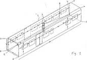
Die vorliegende Erfindung wird im Folgenden anhand einer Zeichnung näher erläutert. Es wird gezeigt in:The present invention will be explained in more detail below with reference to a drawing. It is shown in:
In
Beispielexample
Der Messvorgang wird nach einem Beispiel in den folgenden Schritten vorgenommen.The measuring procedure is carried out according to an example in the following steps.
1. Festlegung des Ist-Koordinatenursprungs.1. Definition of the actual coordinate origin.
Daraus ergibt sich ein Koordinatensystem mit den folgenden 3D Koordinaten (x: Längsrichtung, daher in Fahrtrichtung, y: Querrichtung, daher quer zur Fahrtrichtung und z: oben oder unten).This results in a coordinate system with the following 3D coordinates (x: longitudinal direction, therefore in the direction of travel, y: transverse direction, therefore transverse to the direction of travel and z: top or bottom).
Die Rohkarossen werden fertig lackiert angeliefert. Nach Überprüfung der Karosserie werden die Bohrlöcher abgesteckt. Anschließend werden die Bohrlöcher gebohrt. Mit Hilfe der T-Probe des Lasertrackers von Leica AT 901 MR werden jeweils ca. 8–10 Messpunkte auf den Seitenwänden, den Stirnwänden und dem Boden der Rohkarosse gemessen. Aus den Messpunkten werden in CAD (Polyworks) im Best-Fit-Verfahren neue Flächen für die Seiten- und Stirnwände sowie für den Boden erarbeitet. Parallel zu den so ermittelten neuen Seitenflächen wird eine Mittelebene in CAD ermittelt, die zu den beiden anderen Flächen den gleichen Abstand hat. Daher die Mittelebene ist überall gekennzeichnet durch y = 0. Mit Hilfe der T-Probe werden Messpunkte für die seitliche Begrenzung der sich gegenüberliegenden Türausschnitte (in x-Richtung und z-Richtung) gemessen und in CAD übertragen. Aus den Messpunkten werden in CAD im Best-Fit-Verfahren Flächen erzeugt, die dadurch gekennzeichnet sind, dass sie die beiden Türausschnitte wie mit einem Tunnel verbinden. Abschließend wird eine Mittelebene erzeugt, die äquidistant zu den beiden „seitlichen Tunnelflächen” liegt. Die zuvor erzeugte neue Fläche für den Boden wird nun in z-Richtung bis zur Türoberkante verschoben. Der Ist-Koordinatenursprung liegt im Schnittpunkt der 3 Flächen: nach oben transferierte Bodenfläche, generisch erzeugte Mittelebene zwischen den Seitenwänden und generisch erzeugte Mittelebene zwischen den „Tunnelflächen” der Türöffnungen.The bodyshells are delivered ready painted. After checking the body, the holes are staked. Then the holes are drilled. With the help of the T-Probe of the laser tracker of Leica AT 901 MR approx. 8-10 measuring points are measured on the side walls, the end walls and the floor of the body shell. From the measuring points, CAD (Polyworks) uses the best-fit procedure to develop new surfaces for the side and end walls as well as for the floor. Parallel to the new side surfaces thus determined, a center plane is determined in CAD, which has the same distance to the other two surfaces. Therefore, the middle plane is marked everywhere by y = 0. Using the T-Probe, measuring points for the lateral boundary of the opposite door cutouts (in the x-direction and z-direction) are measured and transferred to CAD. From the measuring points, surfaces are created in CAD using the best-fit method, which are characterized by the fact that they connect the two door cutouts as if they were tunnels. Finally, a median plane is created that is equidistant from the two "lateral tunnel surfaces". The previously created new floor area will now be moved in the z-direction to the upper edge of the door. The actual coordinate origin lies at the intersection of the three surfaces: bottom surface transferred upwards, generically generated center plane between the side walls and generically generated center plane between the "tunnel surfaces" of the door openings.
Mit Hilfe von 5-Diodenpaaren auf jeder T-Probe kann das System erkennen mit welchem Winkel die T-Probe auf die Fläche aufgesetzt wird und welche Raum-Koordinate die Messspitze hat. Je nach Fläche kommt entweder eine gerade bzw. eine um 90° abgewinkelte Spitze auf der T-Probe zum Einsatz. Aktuell wird jede T-Probe alle 4 Wochen kalibriert. Der Zeitaufwand beträgt etwa 30 Minuten je T-Probe.With the aid of 5-diode pairs on each T-probe, the system can detect with which angle the T-probe is placed on the surface and which spatial coordinate has the measuring tip. Depending on the surface, either a straight or a 90 ° angled tip is used on the T-probe. Currently every T-sample is calibrated every 4 weeks. The time required is about 30 minutes per T-sample.
2. Aufkleben von 7 Nestern2. Gluing on 7 nests
Dies erlaubt den Lasertracker jederzeit abzubauen und wieder neu in der Rohkarosse aufzubauen ohne lange Einmessarbeiten.This allows the laser tracker at any time dismantle and rebuild in the body shell without long Einmessarbeiten.
3. Markieren der Mittelachsen3. Mark the center axes
Die Schnittlinie der theoretisch ermittelten Mittelebene zwischen den Seitenwänden wird mit Hilfe der T-Probe und des daran befestigten Körners (punch tool) auf dem Boden markiert. Die Schnittlinie der theoretisch ermittelten Mittelebene in den Türausschnitten wird mit Hilfe der T-Probe und des daran befestigten Körners auf dem Boden und dem oberen Türausschnitt markiert. Man könnte jetzt theoretisch mit Hilfe einer Schnur die Mittelachsen durch das Verbinden der gegenüberliegenden gekörnten Punkte sichtbar machen. Dies ist für nachfolgende Arbeiten mit einfachen Hilfsmitteln sinnvoll.The intersection of the theoretically determined median plane between the sidewalls is marked on the floor using the T-Probe and the punch tool attached to it. The section line of the theoretically determined median plane in the door cutouts is marked on the floor and the upper door opening with the aid of the T-Probe and the attached grain. Theoretically, by means of a string, one could visualize the central axes by connecting the opposite grained points. This is useful for subsequent work with simple tools.
4. Abstecken von Bohrpunkten4. Staking out drilling points
Anhand der Zeichnungen wissen die Anwender an welchen Stellen Bohrpunkte angezeichnet werden müssen. Wenn man mit der T-Probe in die Nähe einer Bohrung kommt, erkennt das System automatisch, um welche Bohrung es sich handelt. Es zeigt dem Anwender auf dem Bildschirm farblich (grün oder rot) an, ob er sich mit seinem Körner innerhalb der vorgegebenen Toleranz befindet. Zusätzlich wird der numerische Wert in mm angegeben, um den der Körner bewegt werden muss.Based on the drawings, the users know where drill points have to be marked. If you come near a hole with the T-Probe, the system automatically detects what hole it is. It indicates to the user on the screen in color (green or red), whether he is with his grains within the specified tolerance. In addition, the numerical value in mm is given, by which the grains must be moved.
Die zurzeit voreingestellte Toleranz beträgt jeweils +/–0,25 mm in x- und z-Richtung im Falle der Seitenwände in y- und z-Richtung im Falle der Stirnwände und in x- und y-Richtung im Falle des Bodens und der Decke. Der Anwender, der die T-Probe mit Körner bedient, markiert die Körnung zusätzlich mit einem Eddingmarker. Handschriftlich vermerkt er den Lochdurchmesser des von der nachfolgenden Bohrtruppe zu bohrenden Lochdurchmessers. Ein weiterer Anwender macht den Körnerpunkt mit Hilfe eines Akkubohrers und 2 mm Spiralbohrer besser sichtbar. Bohrtiefe beträgt etwa 1 mm gerade soviel, dass man die Körnung besser ertasten kann. Normale Waggons haben in der Regel etwa 1.500 Bohrpunkte, für die 2 Personen etwa 1 Schicht benötigen.The currently preset tolerance is +/- 0.25 mm in both the x and z directions for the sidewalls in the y and z directions for the end walls and in the x and y directions for the floor and ceiling , The user who uses the T-Probe with grains also marks the grain with an edding marker. He notes in writing the hole diameter of the hole diameter to be drilled by the following drilling crew. Another user makes the grain point more visible with the help of a cordless drill and a 2 mm twist drill. Drilling depth is about 1 mm just enough to feel the grain better. Normal wagons usually have about 1,500 drilling points, for which 2 people need about 1 shift.
Doppelstockwagen können ca. 4000 Bohrlöcher haben, die noch nicht im Rohbau vorgebohrt wurden. In der Regel haben die Bohrlöcher einen Durchmesser von 5 mm bis 6,5 mm für Nieten. Die Durchmesser variieren von 4,5 mm bis 13,5 mm. Oft werden auch Gewindemuttern eingepresst. Double-decker coaches can have around 4000 holes that have not been pre-drilled in the shell. Typically, the holes have a diameter of 5 mm to 6.5 mm for rivets. The diameters vary from 4.5 mm to 13.5 mm. Often also threaded nuts are pressed.
Durch das erfindungsgemäße Verfahren konnten die geforderten Toleranzen von 0,5 mm deutlich unterschritten werden. Die Bearbeitung ist durch eine Person möglich. Das erfindungsgemäße Verfahren wird mittels eines transportablen Messsystems vor Ort durchgeführt.The inventive method, the required tolerances of 0.5 mm could be significantly below. The processing is possible by one person. The inventive method is carried out by means of a portable measuring system on site.
BezugszeichenlisteLIST OF REFERENCE NUMBERS
- 11
- Fahrzeug, Waggon, WagenkastenVehicle, wagon, car body
- 22
- Lasertrackerlaser Tracker
- 33
- Laserstrahllaser beam
- 44
- Die untere linke Ecke von S1The lower left corner of S1
- 55
- Die obere linke Ecke von S1The upper left corner of S1
- 66
- Die obere rechte Ecke von S1The upper right corner of S1
- 77
- Die untere rechte Ecke von S1The lower right corner of S1
- 88th
- Die rechten unteren Ecke von S2The lower right corner of S2
- 99
- Die rechte obere Ecke von S2The upper right corner of S2
- 1010
- Die obere linke Ecke von S2The upper left corner of S2
- 1111
- unteren linken Ecke von S2lower left corner of S2
- S1S1
- Stirnseite des Waggons (
1 )Front side of the wagon (1 ) - S2S2
- Stirnseite des Waggons (
1 )Front side of the wagon (1 )
ZITATE ENTHALTEN IN DER BESCHREIBUNG QUOTES INCLUDE IN THE DESCRIPTION
Diese Liste der vom Anmelder aufgeführten Dokumente wurde automatisiert erzeugt und ist ausschließlich zur besseren Information des Lesers aufgenommen. Die Liste ist nicht Bestandteil der deutschen Patent- bzw. Gebrauchsmusteranmeldung. Das DPMA übernimmt keinerlei Haftung für etwaige Fehler oder Auslassungen.This list of the documents listed by the applicant has been generated automatically and is included solely for the better information of the reader. The list is not part of the German patent or utility model application. The DPMA assumes no liability for any errors or omissions.
Zitierte PatentliteraturCited patent literature
- DE 4216606 A1[0002]DE 4216606 A1[0002]
- DE 102010000777 A1[0003]DE 102010000777 A1[0003]
- DE 000019927005 C1[0004]DE 000019927005 C1[0004]
Claims (10)
Translated fromGermanPriority Applications (2)
| Application Number | Priority Date | Filing Date | Title |
|---|---|---|---|
| DE102014013724.4ADE102014013724A1 (en) | 2014-09-22 | 2014-09-22 | Method for staking boreholes of a vehicle |
| EP15185678.8AEP2998764A1 (en) | 2014-09-22 | 2015-09-17 | Method of tracking of measuring points |
Applications Claiming Priority (1)
| Application Number | Priority Date | Filing Date | Title |
|---|---|---|---|
| DE102014013724.4ADE102014013724A1 (en) | 2014-09-22 | 2014-09-22 | Method for staking boreholes of a vehicle |
Publications (1)
| Publication Number | Publication Date |
|---|---|
| DE102014013724A1true DE102014013724A1 (en) | 2016-03-24 |
Family
ID=54199531
Family Applications (1)
| Application Number | Title | Priority Date | Filing Date |
|---|---|---|---|
| DE102014013724.4AWithdrawnDE102014013724A1 (en) | 2014-09-22 | 2014-09-22 | Method for staking boreholes of a vehicle |
Country Status (2)
| Country | Link |
|---|---|
| EP (1) | EP2998764A1 (en) |
| DE (1) | DE102014013724A1 (en) |
Cited By (1)
| Publication number | Priority date | Publication date | Assignee | Title |
|---|---|---|---|---|
| DE102017107570A1 (en)* | 2017-04-07 | 2018-10-11 | Testo SE & Co. KGaA | marking |
Families Citing this family (4)
| Publication number | Priority date | Publication date | Assignee | Title |
|---|---|---|---|---|
| US20180108178A1 (en)* | 2016-10-13 | 2018-04-19 | General Electric Company | System and method for measurement based quality inspection |
| CN113884081B (en)* | 2016-11-01 | 2024-02-27 | 北京墨土科技有限公司 | Method and equipment for measuring three-dimensional coordinates of positioning point |
| US10573089B2 (en)* | 2017-11-09 | 2020-02-25 | The Boeing Company | Systems, methods, and tools for spatially-registering virtual content with physical environment in augmented reality platforms |
| CN110360973B (en)* | 2019-08-28 | 2021-02-05 | 合肥工业大学 | Automatic guiding method for miniature workpiece measurement |
Citations (3)
| Publication number | Priority date | Publication date | Assignee | Title |
|---|---|---|---|---|
| DE4216606A1 (en) | 1992-05-20 | 1993-11-25 | Ammendorf Waggonbau | Process for manufacturing and expanding rail vehicle car bodies with high dimensional accuracy |
| DE19927005C1 (en) | 1999-06-09 | 2001-01-25 | Daimler Chrysler Ag | Method and device for positioning and leveling supports for floor construction and for other built-in parts in vehicles, in particular rail vehicles for the transportation of people |
| DE102010000777A1 (en) | 2010-01-11 | 2011-07-14 | Ford Global Technologies, LLC, Mich. | Method for mounting a body component to a body shell and holder |
Family Cites Families (6)
| Publication number | Priority date | Publication date | Assignee | Title |
|---|---|---|---|---|
| TWI310142B (en)* | 2003-05-28 | 2009-05-21 | Hon Hai Prec Ind Co Ltd | Cad-based cav system and method |
| WO2007124009A2 (en)* | 2006-04-21 | 2007-11-01 | Faro Technologies, Inc. | Camera based six degree-of-freedom target measuring and target tracking device with rotatable mirror |
| EP2037214A1 (en)* | 2007-09-14 | 2009-03-18 | Leica Geosystems AG | Method and measuring device for measuring surfaces |
| EP2589982A1 (en)* | 2011-11-03 | 2013-05-08 | Leica Geosystems AG | Laser diode as interferometer laserbeam source in a laser tracker |
| EP2662702A1 (en)* | 2012-05-07 | 2013-11-13 | Leica Geosystems AG | Laser tracker with interferometer and absolute distance measuring unit and calibration method for a laser tracker |
| EP2698596A1 (en)* | 2012-08-16 | 2014-02-19 | Hexagon Technology Center GmbH | Method and system for determining spatial coordinates with a mobile coordinate measuring machine |
- 2014
- 2014-09-22DEDE102014013724.4Apatent/DE102014013724A1/ennot_activeWithdrawn
- 2015
- 2015-09-17EPEP15185678.8Apatent/EP2998764A1/ennot_activeWithdrawn
Patent Citations (3)
| Publication number | Priority date | Publication date | Assignee | Title |
|---|---|---|---|---|
| DE4216606A1 (en) | 1992-05-20 | 1993-11-25 | Ammendorf Waggonbau | Process for manufacturing and expanding rail vehicle car bodies with high dimensional accuracy |
| DE19927005C1 (en) | 1999-06-09 | 2001-01-25 | Daimler Chrysler Ag | Method and device for positioning and leveling supports for floor construction and for other built-in parts in vehicles, in particular rail vehicles for the transportation of people |
| DE102010000777A1 (en) | 2010-01-11 | 2011-07-14 | Ford Global Technologies, LLC, Mich. | Method for mounting a body component to a body shell and holder |
Cited By (1)
| Publication number | Priority date | Publication date | Assignee | Title |
|---|---|---|---|---|
| DE102017107570A1 (en)* | 2017-04-07 | 2018-10-11 | Testo SE & Co. KGaA | marking |
Also Published As
| Publication number | Publication date |
|---|---|
| EP2998764A1 (en) | 2016-03-23 |
Similar Documents
| Publication | Publication Date | Title |
|---|---|---|
| DE10112653B4 (en) | Position bearing system | |
| EP2298508B1 (en) | Measurement of a manipulator | |
| EP1204844B1 (en) | Device for determining wheel and/or axle geometry in motor vehicles | |
| DE102008000833A1 (en) | Measuring head for a chassis measuring system, chassis measuring system and method for determining the position parameters of measuring heads of a chassis measuring system | |
| EP1593930B1 (en) | Apparatus and method for measuring objects | |
| DE102007046287B4 (en) | Method for calibrating a sensor arrangement | |
| EP1285224A1 (en) | Method and device for determining the 3d profile of an object | |
| DE102014013724A1 (en) | Method for staking boreholes of a vehicle | |
| EP2806248A1 (en) | Method for calibrating a detection device and detection device | |
| EP2199828B1 (en) | Method for determining the position of a laser scanner relative to a reference system | |
| DE102022104880B4 (en) | Method for calibrating a portable reference sensor system, portable reference sensor system and use of the portable reference sensor system | |
| EP1316777B1 (en) | Method and device for the three dimensional measuring of workpieces on a machine tool | |
| WO2005090907A1 (en) | Method for locating defective points and marking system | |
| EP2064518B1 (en) | Method for determining distances for measuring the chassis of a motor vehicle | |
| DE202020005627U1 (en) | mobile robot | |
| EP2271890A1 (en) | Chassis-measuring system and method for determining the position parameters of probes of a chassis-measuring system | |
| WO2018036741A1 (en) | Tracking-less projection-based "augmented reality [ar]" method and system for assisting installation for industrial goods, particularly for locating groove blocks for component installation in wagon construction | |
| DE102017003641B4 (en) | Method for measuring coordinates or properties of a workpiece surface | |
| DE102017212261A1 (en) | Measuring system and method for measuring at least one automatic, in particular multi-axis, manipulator | |
| DE102012020719A1 (en) | System for measuring motor car before and after collision test, has multi-measuring chambers including photogrammetry measuring device for optical single point measurement and optical scanning device for surface measurement | |
| DE102010026102B4 (en) | Process for recording structural markings for a manufacturing plant, in particular in vehicle construction | |
| DE102023128153B4 (en) | robot-assisted manufacturing system | |
| DE102014102261A1 (en) | Device and method for measuring measurement objects | |
| DE102021130569A1 (en) | Manufacturing assistance device with at least one locating unit | |
| BE1027090B1 (en) | Method for assigning the intrinsic coordinate system of a first unit of a vehicle for recording the space to the side of the vehicle relative to a vehicle-related coordinate system and device for carrying out the method |
Legal Events
| Date | Code | Title | Description |
|---|---|---|---|
| R012 | Request for examination validly filed | ||
| R082 | Change of representative | Representative=s name:LENDVAI, TOMAS, DIPL.-CHEM. DR.RER.NAT., DE | |
| R119 | Application deemed withdrawn, or ip right lapsed, due to non-payment of renewal fee |