DE102014005915A1 - Device for the generative production of three-dimensional objects - Google Patents
Device for the generative production of three-dimensional objectsDownload PDFInfo
- Publication number
- DE102014005915A1 DE102014005915A1DE102014005915.4ADE102014005915ADE102014005915A1DE 102014005915 A1DE102014005915 A1DE 102014005915A1DE 102014005915 ADE102014005915 ADE 102014005915ADE 102014005915 A1DE102014005915 A1DE 102014005915A1
- Authority
- DE
- Germany
- Prior art keywords
- disc
- protective glass
- laser
- laser system
- coating
- Prior art date
- Legal status (The legal status is an assumption and is not a legal conclusion. Google has not performed a legal analysis and makes no representation as to the accuracy of the status listed.)
- Pending
Links
- 238000004519manufacturing processMethods0.000titleclaimsabstractdescription5
- 239000011521glassSubstances0.000claimsabstractdescription23
- 230000001681protective effectEffects0.000claimsabstractdescription23
- 239000000843powderSubstances0.000claimsabstractdescription15
- 230000005855radiationEffects0.000claimsabstractdescription14
- 238000000034methodMethods0.000claimsabstractdescription10
- 239000004566building materialSubstances0.000claimsabstractdescription8
- 238000010276constructionMethods0.000claimsabstractdescription6
- 238000007711solidificationMethods0.000claimsabstractdescription6
- 230000008023solidificationEffects0.000claimsabstractdescription6
- 239000000155meltSubstances0.000claimsabstractdescription5
- 230000008018meltingEffects0.000claimsabstractdescription5
- 238000002844meltingMethods0.000claimsabstractdescription5
- 238000000149argon plasma sinteringMethods0.000claimsabstractdescription4
- 238000000576coating methodMethods0.000claimsdescription13
- 239000011248coating agentSubstances0.000claimsdescription8
- 230000010287polarizationEffects0.000claimsdescription5
- 230000003287optical effectEffects0.000claims1
- 239000004035construction materialSubstances0.000abstractdescription2
- 238000009434installationMethods0.000abstract1
- 238000011161developmentMethods0.000description2
- 230000018109developmental processEffects0.000description2
- BASFCYQUMIYNBI-UHFFFAOYSA-NplatinumChemical compound[Pt]BASFCYQUMIYNBI-UHFFFAOYSA-N0.000description2
- BUHVIAUBTBOHAG-FOYDDCNASA-N(2r,3r,4s,5r)-2-[6-[[2-(3,5-dimethoxyphenyl)-2-(2-methylphenyl)ethyl]amino]purin-9-yl]-5-(hydroxymethyl)oxolane-3,4-diolChemical compoundCOC1=CC(OC)=CC(C(CNC=2C=3N=CN(C=3N=CN=2)[C@H]2[C@@H]([C@H](O)[C@@H](CO)O2)O)C=2C(=CC=CC=2)C)=C1BUHVIAUBTBOHAG-FOYDDCNASA-N0.000description1
- 230000003667anti-reflective effectEffects0.000description1
- 230000009286beneficial effectEffects0.000description1
- 230000015572biosynthetic processEffects0.000description1
- 238000004140cleaningMethods0.000description1
- 230000001427coherent effectEffects0.000description1
- 230000001419dependent effectEffects0.000description1
- 230000006866deteriorationEffects0.000description1
- 230000000694effectsEffects0.000description1
- 238000005755formation reactionMethods0.000description1
- PCHJSUWPFVWCPO-UHFFFAOYSA-NgoldChemical compound[Au]PCHJSUWPFVWCPO-UHFFFAOYSA-N0.000description1
- 239000010931goldSubstances0.000description1
- 229910052737goldInorganic materials0.000description1
- 239000000463materialSubstances0.000description1
- 229910052751metalInorganic materials0.000description1
- 239000002184metalSubstances0.000description1
- 150000002739metalsChemical class0.000description1
- 229910000510noble metalInorganic materials0.000description1
- 229910052697platinumInorganic materials0.000description1
- 239000010970precious metalSubstances0.000description1
- 230000011514reflexEffects0.000description1
- 238000005245sinteringMethods0.000description1
Images
Classifications
- C—CHEMISTRY; METALLURGY
- C04—CEMENTS; CONCRETE; ARTIFICIAL STONE; CERAMICS; REFRACTORIES
- C04B—LIME, MAGNESIA; SLAG; CEMENTS; COMPOSITIONS THEREOF, e.g. MORTARS, CONCRETE OR LIKE BUILDING MATERIALS; ARTIFICIAL STONE; CERAMICS; REFRACTORIES; TREATMENT OF NATURAL STONE
- C04B35/00—Shaped ceramic products characterised by their composition; Ceramics compositions; Processing powders of inorganic compounds preparatory to the manufacturing of ceramic products
- C04B35/622—Forming processes; Processing powders of inorganic compounds preparatory to the manufacturing of ceramic products
- C04B35/64—Burning or sintering processes
- C—CHEMISTRY; METALLURGY
- C04—CEMENTS; CONCRETE; ARTIFICIAL STONE; CERAMICS; REFRACTORIES
- C04B—LIME, MAGNESIA; SLAG; CEMENTS; COMPOSITIONS THEREOF, e.g. MORTARS, CONCRETE OR LIKE BUILDING MATERIALS; ARTIFICIAL STONE; CERAMICS; REFRACTORIES; TREATMENT OF NATURAL STONE
- C04B2235/00—Aspects relating to ceramic starting mixtures or sintered ceramic products
- C04B2235/60—Aspects relating to the preparation, properties or mechanical treatment of green bodies or pre-forms
- C04B2235/602—Making the green bodies or pre-forms by moulding
- C04B2235/6026—Computer aided shaping, e.g. rapid prototyping
- C—CHEMISTRY; METALLURGY
- C04—CEMENTS; CONCRETE; ARTIFICIAL STONE; CERAMICS; REFRACTORIES
- C04B—LIME, MAGNESIA; SLAG; CEMENTS; COMPOSITIONS THEREOF, e.g. MORTARS, CONCRETE OR LIKE BUILDING MATERIALS; ARTIFICIAL STONE; CERAMICS; REFRACTORIES; TREATMENT OF NATURAL STONE
- C04B2235/00—Aspects relating to ceramic starting mixtures or sintered ceramic products
- C04B2235/65—Aspects relating to heat treatments of ceramic bodies such as green ceramics or pre-sintered ceramics, e.g. burning, sintering or melting processes
- C04B2235/66—Specific sintering techniques, e.g. centrifugal sintering
- C04B2235/665—Local sintering, e.g. laser sintering
Landscapes
- Chemical & Material Sciences (AREA)
- Engineering & Computer Science (AREA)
- Manufacturing & Machinery (AREA)
- Ceramic Engineering (AREA)
- Inorganic Chemistry (AREA)
- Materials Engineering (AREA)
- Structural Engineering (AREA)
- Organic Chemistry (AREA)
- Powder Metallurgy (AREA)
Abstract
Translated fromGermanDescription
Translated fromGermanDie Erfindung betrifft eine Vorrichtung zur generativen Herstellung dreidimensionaler Objekte aus pulverartigem Baumaterial unter Einbringung von Strahlungsenergie, insbesondere eine Lasersinter- oder eine Laserschmelzvorrichtung.The invention relates to a device for the generative production of three-dimensional objects made of powdery building material with the introduction of radiant energy, in particular a laser sintering or a laser melting device.
Bekannte derartige Vorrichtungen weisen in der Regel ein Gehäuse auf, in welchem eine Prozesskammer untergebracht ist. In der Prozesskammer befindet sich ein Bauraum mit einer höhenverlagerbaren Bauplattform, auf welche ein zur Verfestigung mittels Strahlungsenergie vorgesehenes pulverartiges Baumaterial aufgebracht wird. Zur Verfestigung ist ein Laser vorgesehen, der in der Regel am oberen Bereich des Gehäuses angeordnet ist und dessen Laserstrahl über einen Scanner prozessorgesteuert auf die Pulveroberfläche geleitet wird, um dort eine Verfestigung des Pulvers abhängig von den Baudaten zu bewirken.Known such devices usually have a housing in which a process chamber is housed. In the process chamber there is a construction space with a height-displaceable construction platform, onto which a pulverulent construction material intended for solidification by means of radiation energy is applied. For solidification, a laser is provided, which is usually arranged at the upper region of the housing and the laser beam is directed processor-controlled by a scanner on the powder surface, there to cause solidification of the powder depending on the Baudaten.
Da bei einem Pulverschmelz- oder Pulversintervorgang Schmauch- und Materialspritzer auftreten, kann bei Bedarf der empfindliche Scanner durch ein Schutzglas abgedeckt sein, welches von der Laserstrahlung durchsetzt wird. Eine derartige Vorrichtung ist beispielsweise aus
Derartige Vorrichtungen werden auch zur Verarbeitung von Edelmetallen, z. B. Gold oder Platin eingesetzt. Derartige Metalle haben im Bereich des Schmelzepools einen hohen Reflexionsgrad und deswegen die Eigenschaft, den Laserstrahl teilweise „in sich” zu reflektieren.Such devices are also used for the processing of precious metals, eg. As gold or platinum used. Such metals have a high degree of reflection in the region of the melt pool and therefore the property of partially reflecting the laser beam "in itself".
Unter gewissen Umständen kann dies dazu führen, dass die Entladung des Lasers gestört und dadurch instabil wird oder gar zusammenbricht und damit der Bauprozess unterbrochen wird. Um dieses Phänomen zu vermeiden, wurde in der Vergangenheit versucht, mit einem reduzierten Energieeintrag auf Pulverschichten mit relativ hoher Reflexion zu arbeiten. Ein reduzierter Energieeintrag kann allerdings zu einer Verschlechterung der Bauteilqualität führen.In some circumstances, this may cause the discharge of the laser to be disturbed and thereby become unstable or even collapse, thereby interrupting the building process. In order to avoid this phenomenon, attempts have been made in the past to work with reduced energy input on relatively high reflection powder layers. However, a reduced energy input can lead to a deterioration of the component quality.
Der Erfindung liegt die Aufgabe zugrunde, die Vorrichtung mit den Merkmalen des Patentanspruches 1 derart auszubilden, dass auch Edelmetallpulver mit einem relativ hohen Reflexionsgrad im Schmelzepool mit einem hohen Energieeintrag bearbeitet werden können. Diese Aufgabe wird durch die kennzeichnenden Merkmale des Anspruches 1 dadurch gelöst, dass im Strahlengang des Lasers wenigstens eine zumindest teiltransparente Scheibe angeordnet ist, die von dem vom Laser kommenden Strahl durchsetzt wird und die von dem Schmelzepool des Pulverbettes reflektierte Strahlungsanteile zumindest teilweise reflektiert. Vorteilhafte Weiterbildungen ergeben sich aus den Unteransprüchen 2–14.The invention has the object of providing the device with the features of
Als Kern der Erfindung wird mithin eine Beschichtung einer Scheibe im Strahlengang des Lasers angesehen, die Strahlung einer bestimmten Wellenlänge bei Auftreffen auf diese Scheibe in eine Richtung, d. h. in Richtung zum Pulverbett transmittiert, in entgegengesetzter Richtung jedoch reflektiert.As a core of the invention, therefore, a coating of a disc in the beam path of the laser is considered, the radiation of a certain wavelength when hitting this disc in one direction, d. H. transmitted in the direction of the powder bed, but reflected in the opposite direction.
Durch eine derartige Maßnahme werden Rückreflexbildungen in das Lasersystem vermieden, das Lasersystem kann ungestört arbeiten, und ein kontinuierlicher Bauprozess wird dadurch gewährleistet.Such a measure avoids back-reflection formations in the laser system, the laser system can operate undisturbed, and a continuous construction process is thereby ensured.
In vorteilhafter Weiterbildung ist die als Rückreflexfilter ausgebildete Scheibe das im Strahlengang ohnehin angeordnete Schutzglas, das mit einer Beschichtung versehen wird.In an advantageous development, the disk designed as a back-reflex filter is the protective glass, which is arranged anyway in the beam path and is provided with a coating.
Es ist aber auch möglich, als Scheibe eine gesonderte, vor oder hinter dem Schutzglas angeordnete teilreflektierende Scheibe zu verwenden.But it is also possible to use as a separate disk, arranged in front of or behind the protective glass partially reflecting disc.
Die Scheibe kann z. B. als Polarisationsfilter ausgebildet sein, Laserstrahlung ist eine in der Regel linear polarisierte, kohärente Strahlung. Bei Reflektion bei linear polarisierten Strahlung durch die hoch reflektierende Schicht wird die Polarisationsrichtung des Strahles teilweise aufgehoben oder gedreht, so dass durch einen entsprechend justierten Polfilter die Strahlung ungehindert in einer Richtung durch die Scheibe hindurch dringen kann, hinsichtlich der Polarisation verdrehte reflektierte Strahlungsanteile dagegen reduziert oder ausgelöscht werden.The disc can z. B. be designed as a polarizing filter, laser radiation is a generally linearly polarized, coherent radiation. In reflection with linearly polarized radiation through the highly reflective layer, the polarization direction of the beam is partially canceled or rotated, so that through an appropriately adjusted polarizing filter, the radiation can penetrate freely in one direction through the disc, with respect to polarization twisted reflected radiation components, however, reduced or be extinguished.
Dazu ist es vorteilhaft, wenn die Scheibe in einer Drehlagerung angeordnet wird, da dann entsprechende Justierungsmöglichkeiten vorhanden sind.For this purpose, it is advantageous if the disc is arranged in a rotary bearing, since then appropriate adjustment options are available.
Es kann auch vorteilhaft sein, den Neigungswinkel der Scheibe gegenüber dem sie durchsetzenden Laserstrahl veränderbar zu gestalten, durch Veränderung der Neigung lassen sich ebenfalls Rückreflektionen vom Lasersystem fern halten.It may also be advantageous to make the inclination angle of the disc changeable with respect to the laser beam passing through it, and by changing the inclination, it is likewise possible to keep back reflections away from the laser system.
In vorteilhafter Weiterbildung kann die Scheibe auch eine Mehrzahl von Beschichtungen tragen. Die Scheibe kann auch mehrlagig ausgebildet sein oder unterschiedliche Wellenlängen transmittieren bzw. reflektieren. Die Beschichtung kann auf die Scheibe nach Art einer Folie aufgebracht werden, wenn die Folie zwischen zwei Scheibenlagen angeordnet ist, wird sie bei Reinigungsvorgängen der Scheibe in vorteilhafter Weise geschützt.In an advantageous embodiment, the disc can also carry a plurality of coatings. The disk can also be designed in multiple layers or transmit or reflect different wavelengths. The coating can be applied to the disk in the manner of a film, when the film is arranged between two disk layers, it is advantageously protected during cleaning operations of the disk.
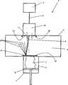
Die Erfindung ist anhand eines Ausführungsbeispiels in der Zeichnung näher erläutert. Diese zeigt eine schematische Darstellung einer Vorrichtung zur generativen Herstellung dreidimensionaler Objekte, nämlich eine Lasersinter- oder Laserschmelzvorrichtung mit einem erfindungsgemäß beschichteten Schutzglas.The invention is explained in more detail with reference to an embodiment in the drawing. These shows a schematic representation of an apparatus for the generative production of three-dimensional objects, namely a laser sintering or laser melting device with a protective glass coated according to the invention.
Die in der Zeichnungsfigur dargestellte Vorrichtung
Im Strahlengang des Lasersystems
Die Scheibe
Die Scheibe
Grundsätzlich ist es möglich, die Scheibe in einer Drehlagerung
Es ist auch möglich, den Neigungswinkel der Scheibe oder des Schutzglases
Die Scheibe
Die Scheibe oder das Schutzglas kann eine Mehrzahl von Beschichtungen tragen, Scheibe
BezugszeichenlisteLIST OF REFERENCE NUMBERS
- 11
- Vorrichtungcontraption
- 22
- Objektobject
- 33
- Baumaterialbuilding materials
- 44
- Lasersystemlaser system
- 55
- Gehäusecasing
- 66
- Prozesskammerprocess chamber
- 77
- Bauraumspace
- 88th
- Bauplattformbuilding platform
- 99
- Laserstrahllaser beam
- 1010
- Scannerscanner
- 1111
- Schutzglasprotective glass
- 1212
- Pulverschichtpowder layer
- 1313
- Scheibedisc
- 1414
- Schmelzepoolmelt pool
- 1515
- reflektierter Strahlungsanteilreflected radiation component
- 1616
- Drehlagerungpivot bearing
ZITATE ENTHALTEN IN DER BESCHREIBUNG QUOTES INCLUDE IN THE DESCRIPTION
Diese Liste der vom Anmelder aufgeführten Dokumente wurde automatisiert erzeugt und ist ausschließlich zur besseren Information des Lesers aufgenommen. Die Liste ist nicht Bestandteil der deutschen Patent- bzw. Gebrauchsmusteranmeldung. Das DPMA übernimmt keinerlei Haftung für etwaige Fehler oder Auslassungen.This list of the documents listed by the applicant has been generated automatically and is included solely for the better information of the reader. The list is not part of the German patent or utility model application. The DPMA assumes no liability for any errors or omissions.
Zitierte PatentliteraturCited patent literature
- DE 102010052206[0003]DE 102010052206[0003]
Claims (14)
Translated fromGermanPriority Applications (1)
| Application Number | Priority Date | Filing Date | Title |
|---|---|---|---|
| DE102014005915.4ADE102014005915A1 (en) | 2014-04-25 | 2014-04-25 | Device for the generative production of three-dimensional objects |
Applications Claiming Priority (1)
| Application Number | Priority Date | Filing Date | Title |
|---|---|---|---|
| DE102014005915.4ADE102014005915A1 (en) | 2014-04-25 | 2014-04-25 | Device for the generative production of three-dimensional objects |
Publications (1)
| Publication Number | Publication Date |
|---|---|
| DE102014005915A1true DE102014005915A1 (en) | 2015-10-29 |
Family
ID=54261440
Family Applications (1)
| Application Number | Title | Priority Date | Filing Date |
|---|---|---|---|
| DE102014005915.4APendingDE102014005915A1 (en) | 2014-04-25 | 2014-04-25 | Device for the generative production of three-dimensional objects |
Country Status (1)
| Country | Link |
|---|---|
| DE (1) | DE102014005915A1 (en) |
Cited By (1)
| Publication number | Priority date | Publication date | Assignee | Title |
|---|---|---|---|---|
| EP3296080A1 (en) | 2016-09-19 | 2018-03-21 | CL Schutzrechtsverwaltungs GmbH | Apparatus for manufacturing of three-dimensional objects |
Citations (5)
| Publication number | Priority date | Publication date | Assignee | Title |
|---|---|---|---|---|
| DE202004007214U1 (en)* | 2004-05-01 | 2004-08-12 | Laserinstitut Mittelsachsen E.V. | Device for preparation of microbodies has a particle transport device, a laser with an optionally modulated beam for sintering and/or melting of para- or ferromagnetic particles, and a device providing a magnetic field |
| US20100173096A1 (en)* | 2009-01-06 | 2010-07-08 | Kritchman Eliahu M | Method and apparatus for monitoring electro-magnetic radiation power in solid freeform fabrication systems |
| DE102010028213A1 (en)* | 2010-04-26 | 2011-10-27 | Jt Optical Engine Gmbh + Co. Kg | Optical isolator, has Faraday-rotator arranged between input and output polarization filters, where laser beam runs from front side through Faraday-element based on reflection at reflector and is reflected at rear side of Faraday-element |
| DE102010052206A1 (en) | 2010-11-10 | 2012-05-10 | Cl Schutzrechtsverwaltungs Gmbh | Device useful for manufacturing three-dimensional object by successive solidification of layers of building material, comprises deflection device which redirects laterally injected protective gas stream back to protective gas suction |
| DE102013010771A1 (en)* | 2013-04-22 | 2014-10-23 | Airbus Defence and Space GmbH | Protective device for generative manufacturing processes, manufacturing device provided therewith and generative manufacturing process feasible therewith |
- 2014
- 2014-04-25DEDE102014005915.4Apatent/DE102014005915A1/enactivePending
Patent Citations (5)
| Publication number | Priority date | Publication date | Assignee | Title |
|---|---|---|---|---|
| DE202004007214U1 (en)* | 2004-05-01 | 2004-08-12 | Laserinstitut Mittelsachsen E.V. | Device for preparation of microbodies has a particle transport device, a laser with an optionally modulated beam for sintering and/or melting of para- or ferromagnetic particles, and a device providing a magnetic field |
| US20100173096A1 (en)* | 2009-01-06 | 2010-07-08 | Kritchman Eliahu M | Method and apparatus for monitoring electro-magnetic radiation power in solid freeform fabrication systems |
| DE102010028213A1 (en)* | 2010-04-26 | 2011-10-27 | Jt Optical Engine Gmbh + Co. Kg | Optical isolator, has Faraday-rotator arranged between input and output polarization filters, where laser beam runs from front side through Faraday-element based on reflection at reflector and is reflected at rear side of Faraday-element |
| DE102010052206A1 (en) | 2010-11-10 | 2012-05-10 | Cl Schutzrechtsverwaltungs Gmbh | Device useful for manufacturing three-dimensional object by successive solidification of layers of building material, comprises deflection device which redirects laterally injected protective gas stream back to protective gas suction |
| DE102013010771A1 (en)* | 2013-04-22 | 2014-10-23 | Airbus Defence and Space GmbH | Protective device for generative manufacturing processes, manufacturing device provided therewith and generative manufacturing process feasible therewith |
Cited By (2)
| Publication number | Priority date | Publication date | Assignee | Title |
|---|---|---|---|---|
| EP3296080A1 (en) | 2016-09-19 | 2018-03-21 | CL Schutzrechtsverwaltungs GmbH | Apparatus for manufacturing of three-dimensional objects |
| DE102016117633A1 (en) | 2016-09-19 | 2018-03-22 | Cl Schutzrechtsverwaltungs Gmbh | Device for producing three-dimensional objects |
Similar Documents
| Publication | Publication Date | Title |
|---|---|---|
| WO2014135296A1 (en) | Coated disk with partially uncoated regions | |
| EP2850469A1 (en) | Dlc coating for an optical ir component and optical ir components having said dlc coating | |
| DE102015101428A1 (en) | Optical module and optical functional film for optical devices | |
| DE112015000587T5 (en) | System and method for laser cutting sapphire using multiple gas media | |
| DE102010029321A1 (en) | Method and device for spatially periodic modification of a substrate surface | |
| DE19910725A1 (en) | Aperture for high density laser radiation minimizes absorption heating | |
| EP3541225B1 (en) | Watch glass and method for producing a watch glass | |
| EP1110450B1 (en) | Device for protecting birds on a transparent material, glass with a device for protecting birds | |
| DE102019219177A1 (en) | Optical element with a protective coating, process for its production and optical arrangement | |
| DE102014005915A1 (en) | Device for the generative production of three-dimensional objects | |
| DE102008022724B4 (en) | Pulse shaper and infrared laser with pulse shaper | |
| DE102013010771A1 (en) | Protective device for generative manufacturing processes, manufacturing device provided therewith and generative manufacturing process feasible therewith | |
| DE1614766A1 (en) | Solid state image amplifier | |
| EP2103978A1 (en) | Layer system for heating optical surfaces and simultaneous reflex reduction | |
| WO2021037520A1 (en) | Method and apparatus for cutting a workpiece by means of a laser beam | |
| DE102014213970B4 (en) | Method and protective device for limiting an optical power | |
| EP3953099B1 (en) | Method for terminating optical radiation and optical beam trap embodied therefor | |
| DE102023115109A1 (en) | DISPLAY PROTECTION DEVICE AND METHOD FOR PRODUCING A DISPLAY PROTECTION DEVICE | |
| EP2125251B1 (en) | Coating method for optical plastic substrates | |
| EP3420386B1 (en) | Optical coating and method for producing an optical coating with reduced light scattering | |
| DE202014008103U1 (en) | Optical polarization attenuation filter for solar observation in white light | |
| DE102014205907A1 (en) | Protection device for protection against laser radiation | |
| EP3140682B1 (en) | Method for limiting optical power, power limiter and apparatus equipped therewith | |
| EP2911808B1 (en) | Uv irradiation device for clocked operation | |
| DE102022130159A1 (en) | DISPLAY PROTECTION DEVICE AND METHOD FOR THE PRODUCTION THEREOF |
Legal Events
| Date | Code | Title | Description |
|---|---|---|---|
| R012 | Request for examination validly filed | ||
| R016 | Response to examination communication | ||
| R016 | Response to examination communication | ||
| R079 | Amendment of ipc main class | Free format text:PREVIOUS MAIN CLASS: B22F0003105000 Ipc:B22F0012440000 | |
| R016 | Response to examination communication | ||
| R081 | Change of applicant/patentee | Owner name:CONCEPT LASER GMBH, DE Free format text:FORMER OWNER: CL SCHUTZRECHTSVERWALTUNGS GMBH, 96215 LICHTENFELS, DE |