DE102014002580A1 - Closing device for a motor vehicle hood - Google Patents
Closing device for a motor vehicle hoodDownload PDFInfo
- Publication number
- DE102014002580A1 DE102014002580A1DE102014002580.2ADE102014002580ADE102014002580A1DE 102014002580 A1DE102014002580 A1DE 102014002580A1DE 102014002580 ADE102014002580 ADE 102014002580ADE 102014002580 A1DE102014002580 A1DE 102014002580A1
- Authority
- DE
- Germany
- Prior art keywords
- gap
- door
- lock
- locking
- motor unit
- Prior art date
- Legal status (The legal status is an assumption and is not a legal conclusion. Google has not performed a legal analysis and makes no representation as to the accuracy of the status listed.)
- Pending
Links
Images


Classifications
- E—FIXED CONSTRUCTIONS
- E05—LOCKS; KEYS; WINDOW OR DOOR FITTINGS; SAFES
- E05B—LOCKS; ACCESSORIES THEREFOR; HANDCUFFS
- E05B81/00—Power-actuated vehicle locks
- E05B81/12—Power-actuated vehicle locks characterised by the function or purpose of the powered actuators
- E05B81/20—Power-actuated vehicle locks characterised by the function or purpose of the powered actuators for assisting final closing or for initiating opening
- E—FIXED CONSTRUCTIONS
- E05—LOCKS; KEYS; WINDOW OR DOOR FITTINGS; SAFES
- E05B—LOCKS; ACCESSORIES THEREFOR; HANDCUFFS
- E05B81/00—Power-actuated vehicle locks
- E05B81/54—Electrical circuits
- E05B81/64—Monitoring or sensing, e.g. by using switches or sensors
Landscapes
- Lock And Its Accessories (AREA)
- Power-Operated Mechanisms For Wings (AREA)
Abstract
Translated fromGermanDescription
Translated fromGermanDie Erfindung betrifft eine Schließvorrichtung mit einem Schloss für eine Tür oder eine Klappe und insbesondere für eine Haube eines Kraftfahrzeugs mit einem Gesperre umfassend eine Drehfalle und wenigstens eine Sperrklinke für ein Verrasten der Drehfalle.The invention relates to a locking device with a lock for a door or a flap and in particular for a hood of a motor vehicle with a locking mechanism comprising a rotary latch and at least one pawl for locking the rotary latch.
Ein Schloss einer Schließvorrichtung der eingangs genannten Art dient zum zeitweisen Verschließen von Öffnungen in Kraftfahrzeugen oder Gebäuden mit Hilfe von Türen oder Klappen. Im geschlossenen Zustand eines solchen Schlosses greift die Drehfalle mit zwei Armen (Lastarm sowie Fangarm genannt) um einen insbesondere bügelförmig ausgeführten Schließbolzen herum. Der Schließbolzen kann im Fall eines Kraftfahrzeugs an einer Tür oder Klappe des Kraftfahrzeugs befestigt sein und dann das Schloss an der Karosserie oder umgekehrt. Im Fall eines Kraftfahrzeugs gibt es insbesondere Seitentürschlösser, Heckklappenschlösser und Haubenschlösser bzw. Motorhaubenschlösser. Die vorliegende Erfindung ist besonders vorteilhaft für Fronthauben bzw. Frontklappen, die sich in üblicher Fahrtrichtung eines Kraftfahrzeugs gesehen vorne befinden.A lock of a locking device of the type mentioned is used for temporary closure of openings in motor vehicles or buildings by means of doors or flaps. In the closed state of such a lock, the rotary latch engages with two arms (called load arm and tentacle) around a particular bow-shaped locking bolt around. The locking bolt may be attached in the case of a motor vehicle to a door or flap of the motor vehicle and then the lock on the body or vice versa. In the case of a motor vehicle, there are in particular side door locks, tailgate locks and hood locks or bonnet locks. The present invention is particularly advantageous for front hoods or front flaps, which are seen in the usual direction of travel of a motor vehicle front.
Das Schloss umfasst regelmäßig einen Schlosskasten oder eine Schlossplatte sowie einen Schlossdeckel, mit dessen Hilfe der Schlosskasten verschlossen wird. Schlosskasten und Schlossdeckel werden Schlossgehäuse genannt. Das Gesperre, also Drehfalle und Sperrklinke, sind grundsätzlich am Schlosskasten drehbar angebracht. Aus Stabilitätsgründen bestehen Schlosskasten, Drehfalle und/oder Sperrklinke vorteilhaft aus Metall. Der Schlossdeckel besteht u. a. aus Gewichtsgründen vorteilhaft aus Kunststoff. Eine Schlossplatte oder Schlosskasten umfassen, bei Seitentürschlössern, vornehmlich einen Einlaufbereich für den Schließbolzen. Es handelt sich dabei um eine beispielsweise U-förmige Ausbuchtung, die es dem Schließbolzen ermöglicht, in die Drehfalle einzufallen.The lock regularly includes a lock case or a lock plate and a lock cover, with the aid of the lock case is closed. Lock case and lock cover are called lock case. The locking mechanism, so catch and pawl are basically rotatably mounted on the lock case. For stability reasons lock case, catch and / or pawl advantageously made of metal. The lock lid is u. a. for reasons of weight advantageous from plastic. A lock plate or lock case, in side door locks, primarily an inlet region for the locking pin. It is an example, U-shaped bulge, which allows the locking pin to fall into the catch.
Wie üblich, kann das Schloss karosserieseitig oder hauben- bzw. türseitig angeordnet werden. Im erstgenannten Fall wird das Schloss an einer Kraftfahrzeugkarosserie beispielsweise durch Schrauben festgelegt. Die an zweiter Stelle genannte Variante korrespondiert dazu, dass das Schloss und mit ihm das Türschloss im Innern oder an einer Tür, einer Haube, einer Klappe oder dergleichen angebracht wird.As usual, the lock can be arranged on the body side or hood or door side. In the former case, the lock is fixed to a motor vehicle body, for example, by screws. The variant mentioned in the second corresponds to the fact that the lock and with it the door lock is mounted inside or on a door, a hood, a flap or the like.
Folgerichtig werden in der Praxis beispielsweise Seitentürschlösser, Heckklappenschlösser und Haubenschlösser bzw. Motorhaubenschlösser unterschieden. Diese fallen sämtlich unter den Begriff Kraftfahrzeugschloss. Eine Schließvorrichtung umfasst besonders bevorzugt ein solches Kraftfahrzeugschloss.Consequently, in practice, for example, side door locks, tailgate locks and hood locks or bonnet locks are distinguished. These fall all under the term motor vehicle lock. A locking device particularly preferably comprises such a motor vehicle lock.
Im Rahmen der Erfindung ist das Schlossgehäuse regelmäßig karosserieseitig angebracht, findet sich also an einer zugehörigen Kraftfahrzeugkarosserie. Demgegenüber ist der Schließbolzen an eine Haube angeschlossen, so dass meistens ein Haubenschloss bzw. Motorhaubenschloss betrachtet wird. Grundsätzlich kann aber auch umgekehrt vorgegangen werden. Dann ist der Schließbolzen an die Karosserie bzw. Kraftfahrzeugkarosserie angeschlossen, wohingegen das Schlossgehäuse und mit ihm das Kraftfahrzeugschloss eine Anbringung an der Haube oder allgemein türseitig erfährt.In the context of the invention, the lock housing is regularly mounted on the body side, so it is found on an associated vehicle body. In contrast, the locking bolt is connected to a hood, so that usually a hood lock or bonnet lock is considered. In principle, however, the procedure can also be reversed. Then the locking bolt is connected to the body or vehicle body, whereas the lock housing and with it the motor vehicle lock learns an attachment to the hood or the door generally.
Erreicht die Drehfalle eines solchen Schlosses ausgehend von einer geöffneten Stellung durch Verschwenken eine Schließstellung, so wird die Drehfalle schließlich mittels der Sperrklinke verrastet. Ein solches Verschwenken wird durch den Schließbolzen (auch „Schlosshalter” genannt) erreicht, wenn dieser durch ein Schließen einer zugehörigen Tür oder Klappe in die Drehfalle einfällt. Eine Sperrfläche der Sperrklinke liegt im verrasteten Zustand an einer Sperrfläche der Drehfalle an, wodurch verhindert wird, dass die Drehfalle in Richtung geöffnete Stellung zurückgedreht werden kann. Der Schließbolzen kann das Gesperre in der Schließstellung nicht mehr verlassen.Reached the catch of such a lock, starting from an open position by pivoting a closed position, the catch is finally locked by means of the pawl. Such pivoting is achieved by the locking bolt (also called "lock retainer") when it engages by closing an associated door or flap in the catch. A locking surface of the pawl is in the locked state of a locking surface of the rotary latch, thereby preventing that the catch can be turned back in the open position. The locking pin can not leave the locking mechanism in the closed position.
Für ein Öffnen wäre es erforderlich, die Sperrklinke aus ihrer Raststellung heraus zu bewegen. Ist die Sperrklinke aus ihrer Raststellung heraus bewegt worden, so dreht sich die Drehfalle in Richtung geöffnete Stellung. In der geöffneten Stellung der Drehfalle und damit in der geöffneten Stellung des Gesperres kann der Schließbolzen das Schloss verlassen. Die Tür oder Klappe kann so wieder geöffnet werden.For opening it would be necessary to move the pawl out of its detent position. If the pawl has been moved out of its detent position, the rotary latch rotates in the direction of the open position. In the open position of the catch and thus in the open position of the locking mechanism, the locking bolt can leave the lock. The door or flap can be opened again.
Es gibt Schlösser mit zwei verschiedenen Raststellungen der Drehfalle. Die Drehfalle kann dann zunächst in der sogenannten Vorrastposition verrastet werden und durch ein Weiterdrehen in Schließrichtung schließlich in der sogenannten Hauptrastposition. In der Vorrastposition kann zwar ein Schließbolzen das Gesperre nicht mehr verlassen. Eine entsprechende Tür oder Klappe ist aber noch nicht vollständig geschlossen. Eine solche Tür oder Klappe ist erst dann vollständig verschlossen, wenn die Drehfalle bis zur Hauptrastposition gedreht und hier verrastet wird. Für ein Verrasten in der Vorrastposition kann eine zweite Sperrklinke vorgesehen sein. Es ist aber auch möglich, die Drehfalle mit nur einer Sperrklinke sowohl in der Vorrastposition als auch in der Hauptrastposition zu verrasten. Ein solches Schloss kann einen elektrischen Antrieb umfassen, um ein in der Vorrastposition verrastetes Gesperre in die Hauptrastposition zu bewegen, um schließlich das Gesperre in der Hauptrastposition zu verrasten. Ein solches Schloss wird auch Schloss mit Zuziehhilfe genannt. Ein Schloss mit Zuziehhilfe ist aus der
Die
Um ein Schloss öffnen zu können, gibt es eine Betätigungseinrichtung. Wird die Betätigungseinrichtung betätigt, so öffnet sich das Gesperre. Ein Griff einer Tür oder einer Klappe kann Teil der Betätigungseinrichtung sein. Dieser Griff wird in der Regel über ein Gestänge oder einen Bowdenzug mit einem Betätigungshebel des Schlosses verbunden. Wird der Griff betätigt, so wird mittels des Gestänges oder des Bowdenzugs der Betätigungshebel des Schlosses so verschwenkt, dass sich das Schloss öffnet. Ein Kraftfahrzeug kann einen in der Regel schwenkbaren Außengriff, der von außen erreichbar ist, und/oder einen in der Regel schwenkbaren Innengriff, der von innen erreichbar ist, aufweisen.To open a lock, there is an actuator. When the actuating device is actuated, the locking mechanism opens. A handle of a door or flap may be part of the actuator. This handle is usually connected via a linkage or a Bowden cable with an actuating lever of the castle. If the handle is actuated, the actuating lever of the lock is pivoted by means of the linkage or Bowden cable so that the lock opens. A motor vehicle can have a generally pivotable outer handle, which can be reached from the outside, and / or a generally pivotable inner handle, which can be reached from the inside.
Wird ein Gesperre eines Kraftfahrzeugs durch Schließen einer Tür oder Klappe verrastet, so verbleibt grundsätzlich zwischen der Tür bzw. Klappe und der angrenzenden Karosserie ein Spalt. Ein solcher Spalt soll vor allem bei Hauben, die sich in üblicher Fahrtrichtung gesehen vorne befinden, so gering wie möglich sein, um nachteilhafte Luftverwirbelungen im Frontbereich und damit einhergehende Luftwiderstände während einer Fahrt zu vermeiden. Eine möglichst spaltfreie, geschlossene Oberfläche ist aber auch aus optischen Gründen erwünscht.If a locking mechanism of a motor vehicle is locked by closing a door or flap, a gap generally remains between the door or flap and the adjacent body. Such a gap should be as low as possible, especially in hoods, which are seen in the usual direction forward to avoid adverse air turbulence in the front area and concomitant air resistance during a ride. A possible gap-free, closed surface is also desirable for optical reasons.
In der Praxis und im Stand der Technik nach der
Im Allgemeinen wird jedoch meistens nur mit einer Schließhilfe bzw. Schließeinrichtung gearbeitet, die eine beispielsweise in Vorraststellung des Gesperres befindliche Kraftfahrzeugtür in die Hauptraststellung motorisch zuzieht. Dazu wird im gattungsbildenden Stand der Technik nach der
In neuerer Zeit und insbesondere bei sogenannten Haubenschlössern, also Kraftfahrzeugtürschlössern an einer Kraftfahrzeughaube oder im Bereich der Kraftfahrzeughaube, ergeben sich nun Anforderungen dahingehend, einen Spalt zwischen der Kraftfahrzeugtür bzw. der Kraftfahrzeughaube und der Kraftfahrzeugkarosserie so gering wie möglich einzustellen und möglichst bis auf 0 mm oder nahezu 0 mm zu verringern. Diese Anforderung erklärt sich nicht nur aufgrund ästhetischer Überlegungen, die eine möglichst glattflächige und geschlossene Oberfläche für ein modernes Kraftfahrzeug fordern. Sondern die Größe des Spaltes hat insbesondere in diesem Bereich unmittelbare Auswirkungen auf Luftverwirbelungen im Frontbereich, die je nach ihrer Entstehung und Ausprägung den Luftwiderstand negativ beeinflussen können. An dieser Stelle fehlen bisher überzeugende Lösungen. Hier setzt die Erfindung in einer vorteilhaften Ausgestaltung ein.In recent times, and in particular in so-called hood locks, so motor vehicle door locks on a motor vehicle hood or in the field of motor vehicle hood, there are now requirements to set a gap between the motor vehicle door or the motor vehicle body and the vehicle body as low as possible and possibly up to 0 mm or to reduce almost 0 mm. This requirement is explained not only due to aesthetic considerations that require a smooth surface as possible and closed surface for a modern motor vehicle. But the size of the gap has, especially in this area, immediate effects on air turbulences in the front area, which can negatively influence the air resistance depending on their formation and expression. At this point, convincing solutions are missing so far. This is where the invention in an advantageous embodiment.
Die deutsche Voranmeldung
Beim Montieren eines Schlosses soll ein bestimmtes Spaltmaß zwischen Türe oder Klappe und Karosserie hergestellt werden oder kein Spaltmaß, d. h. der Türspalt oder Haubenspalt bildet einen Anschlag. Dazu ist eine genaue Justage des Schließbolzens, meist an der Tür oder Klappe des Kraftfahrzeugs befestigt, nötig. Diese ist dann besonders schwierig, wenn der Spalt einen Anschlag bilden soll, da es keine Toleranz unterhalb des Spaltmaßes „0” gibt. Bislang wird in der Regel das Schloss karosserieseitig verbaut und fixiert. Sodann wird tür- oder haubenseitig der Schließbolzen in seiner ungefähren Position montiert. Dann wird iterativ die Türe oder Haube geschlossen, um das Schloss zu Verriegeln. Der Arbeiter schätzt die Fehlstellung des Schließbolzens ab, entriegelt und öffnet die Türe oder Haube und verändert die Position des Schließbolzens. Diese Schritte werden wiederholt, bis das gewünschte Spaltmaß vorliegt. Abschließend wird gegebenenfalls der Schließbolzen in der eingestellten Position entgültig fixiert. Der Schließbolzen ist üblicherweise in der Türe oder Klappe eingeschraubt, so dass mittels Verdrehen des Gewindes das Spaltmaß justiert werden kann When mounting a lock to a certain gap between the door or flap and body to be made or no gap, ie the door gap or hood gap forms a stop. For this purpose, an exact adjustment of the locking bolt, usually attached to the door or flap of the motor vehicle, necessary. This is particularly difficult if the gap is to form a stop, since there is no tolerance below the gap dimension "0". So far, the lock is usually installed and fixed on the body side. Then, the door or hood side of the locking pin is mounted in its approximate position. Then the door or hood is iteratively closed to lock the lock. The worker estimates the misalignment of the locking bolt, unlocks and opens the door or hood and changes the position of the locking bolt. These steps are repeated until the desired gap is reached. Finally, if necessary, the locking pin is finally fixed in the set position. The locking pin is usually screwed into the door or flap, so that by means of twisting the thread, the gap can be adjusted
Es ist daher Aufgabe der Erfindung eine Schließvorrichtung mit einem Schloss für eine Tür oder eine Klappe eines Kraftfahrzeuges zu schaffen, welches leichter im Hinblick auf gewünschte Spaltmaße justiert werden kann.It is therefore an object of the invention to provide a locking device with a lock for a door or a flap of a motor vehicle, which can be easily adjusted in terms of desired gap dimensions.
Zur Lösung der Aufgabe umfasst eine Schließvorrichtung die Merkmale des Anspruchs 1. Vorteilhafte Ausgestaltungen ergeben sich aus den abhängigen Ansprüchen.To achieve the object, a closing device comprises the features of
Soweit nachfolgend nichts anderes angegeben, kann der Gegenstand der Erfindung die vorgenannten Merkmale einzeln oder in beliebiger Kombination aufweisen.Unless otherwise stated below, the subject matter of the invention may have the aforementioned features individually or in any combination.
Eine Schließvorrichtung für eine Tür oder Klappe weist ein Schloss mit einem Gesperre aus Drehfalle und Sperrklinke für ein Verrasten der Drehfalle auf. Dabei kommt es nicht darauf an, ob dieses nur eine Rastposition oder eine Vorrast- und eine Hauptrastposition aufweist. Maßgeblich ist hier, dass das Schloss mittels seines Gesperres in seiner Rastposition einen Schließbolzen zu verriegeln vermag. Der Schließbolzen gehört nicht zum Schloss und ist in der Regel an der Türe oder Klappe befestigt.A locking device for a door or flap has a lock with a locking mechanism of the catch and pawl for locking the catch. It does not matter whether this has only one locking position or a pre-locking and a main detent position. Decisive here is that the lock is able to lock by means of its locking mechanism in its locking position a locking bolt. The locking pin is not part of the lock and is usually attached to the door or flap.
Die Erfindung liegt nun darin, dass das Schloss beweglich angeordnet ist und mittels eines Antriebs verfahrbar, insbesondere verschwenkbar ist, derart, dass ein bestimmter Türspalt oder Haubenspalt eingestellt werden kann, wenn ein Schließbolzen in der Rastposition im Gesperre verriegelt ist. Dies ermöglicht ein Erreichen des gewünschten Spaltmaßes über einen Antrieb und es ist nicht nötig, den Schließbolzen iterativ zu justieren. Es findet also ein Justieren unter Ausnutzung der Beweglichkeit des Schlosses mit darin verriegelter Türe oder Klappe im Zusammenspiel mit dem Antrieb statt, anstelle des wiederholten Veränderns der Stellung des Schließbolzens, was mehrere Arbeitsschritte erfordern würde.The invention lies in the fact that the lock is arranged to be movable and by means of a drive movable, in particular pivotable, such that a certain door gap or hood gap can be adjusted when a locking pin is locked in the locking position in the locking mechanism. This makes it possible to achieve the desired gap dimension via a drive and it is not necessary to iteratively adjust the locking pin. Thus, it takes place an adjustment taking advantage of the mobility of the lock with locked door or flap in interaction with the drive, instead of repeatedly changing the position of the locking bolt, which would require several steps.
Die Beweglichkeit des Schlosses im Sinn der Erfindung liegt immer dann vor, wenn die Position des bereits in Raststellung befindlichen Schließbolzens verändert werden kann. Diese Position kann z. B. zur Bewegung des ganzen Schlosses oder der maßgeblichen Teile davon erfolgen.The mobility of the castle in the sense of the invention is always present when the position of the already in detent position locking bolt can be changed. This position can z. B. to move the whole castle or the relevant parts thereof.
Vorzugsweise ist der Antrieb als Justiervorrichtung ausgelegt, derart dass ein bestimmter, beim Vorliegen der Rastposition gewünschter Türspalt oder Haubenspalt justiert werden kann, ohne dass der Schließbolzen relativ zur Tür oder Klappe justiert werden muss. Die Bedienung des Antriebs ermöglicht daher das erstmalige Justieren des Schlosses. Nach Vorliegen der Rastposition wird der Antrieb also solange betätigt, bis das gewünschte Spaltmaß erreicht ist. Die Endposition des Verfahrweges wird dann gespeichert, sei es elektronisch, z. B. mittels Schrittmotoren, oder mechanisch, z. B. durch einen Schalter. Bei späteren Schließvorgängen wird dann nach Einnahme der Rastposition des Schließbolzens der Antrieb erneut die gespeicherte Endposition anfahren und damit das gewünschte Spaltmaß einstellen.Preferably, the drive is designed as an adjusting device, such that a certain, in the presence of the locking position desired door gap or hood gap can be adjusted without the locking pin must be adjusted relative to the door or flap. The operation of the drive therefore allows the first-time adjustment of the lock. After the presence of the detent position, the drive is thus actuated until the desired gap is reached. The end position of the travel is then stored, be it electronically, z. B. by stepper motors, or mechanically, for. B. by a switch. In subsequent closing operations, the drive will then approach the stored end position again after taking the locking position of the locking bolt and thus set the desired gap size.
Eine bevorzugte Art der. Speicherung der Endposition des Antriebs erfolgt mittels eines Sensors. Dazu umfasst der Antrieb einen Sensor, insbesondere Schalter oder Mikroschalter, welcher derart angeordnet ist, dass sein Schaltpunkt bei im Schloss in der Rastposition verriegeltem Schließbolzen aktiviert werden kann, sobald ein gewünschter Türspalt oder Haubenspalt erreicht ist. Das Justieren erfolgt z. B. wie folgt: Nach Vorliegen der Rastposition wird der Antrieb solange betätigt, bis das gewünschte Spaltmaß erreicht ist. Die Endposition des Verfahrweges wird dann gespeichert, indem der Sensor so montiert wird, dass er in der Endposition befindliche bewegliche Bauteile des Schlosses registrieren kann, also genau in dieser Position aktiviert wird. Bei aktiviertem Sensor stoppt dann der Antrieb und verhindert so eine unnötige Belastung des Antriebs. Im einfachsten Fall ist der Sensor ein Mikroschalter, der wie oben beschrieben an geeigneter Stelle montiert ist.A preferred type of. Storage of the end position of the drive by means of a sensor. For this purpose, the drive comprises a sensor, in particular switch or micro-switch, which is arranged such that its switching point can be activated when locked in the lock in the locking position locking pin as soon as a desired door gap or hood gap is reached. The adjustment takes place z. B. as follows: After the presence of the detent position, the drive is actuated until the desired gap is reached. The end position of the travel is then stored by the sensor is mounted so that it can register in the end position movable components of the lock, that is activated exactly in this position. When the sensor is activated, the drive then stops and thus prevents an unnecessary load on the drive. In the simplest case, the sensor is a microswitch, which is mounted at a suitable location as described above.
Wenn der Sensor beweglich befestigt ist und mittels Stellmitteln, insbesondere Rasten, zur Festlegung des Schaltpunkts fixierbar ist, wird die Montage des Sensors und damit die Justierung des Schlosses weiter vereinfacht. Es muss kein spezieller Montageort für den Sensor ausgewählt werden, sondern der Sensor wird entlang des vorgesehenen Weges verfahren oder verschwenkt, bis er von Bauteilen des in Endposition stehenden Schlosses aktviert wird. Die Stellmittel fixieren den Sensor in dieser Position. Wenn als Stellmittel Rasten genutzt werden, ist die Bewegung und gleichzeitige Fixierung des Sensors gegeben und kann daher zum Beispiel mit einem Handgriff erfolgen.If the sensor is movably mounted and by means of adjusting means, in particular notches, for fixing the switching point can be fixed, the mounting of the sensor and thus the adjustment of the lock is further simplified. There is no need to select a specific mounting location for the sensor, but the sensor is along the intended path moved or pivoted until it is activated by components of the castle in the final position. The adjusting means fix the sensor in this position. If notches are used as adjusting means, the movement and simultaneous fixing of the sensor is given and can therefore be done, for example, with a handle.
In der kinematischen Umkehrung der letztgenannten Ausgestaltung kann natürlich alternativ der Sensor starr mit dem Schloss verbunden sein und ein Anschlag für den Sensor vorgesehen sein, welcher beweglich befestigt ist und mittels Stellmitteln, insbesondere Rasten, zur Festlegung des Schaltpunkts fixierbar ist. Es wird daher nicht der Sensor justiert, sondern dessen Anschlag.In the kinematic reversal of the latter embodiment, of course, alternatively, the sensor may be rigidly connected to the lock and be provided a stop for the sensor, which is movably mounted and by means of adjusting means, in particular notches, for fixing the switching point can be fixed. It is therefore not the sensor adjusted, but its stop.
In beiden Fällen ist es bevorzugt, dass die Stellmittel derart sind, dass sie ohne Werkzeug, verstellbar und fixierbar sind, aber im Betrieb des Fahrzeuges und beim Ziehen an der Tür oder Klappe nicht verstellbar sind. Dies kann z. B. über entsprechend ausgelegte Rasten, die vorzugsweise als Einwegrasten ausgebildet sind, geschehen. Beispielsweise kann zunächst beim Justieren mittels des Antriebs bei in Rastposition befindlicher Klappe oder Türe das gewünschte Spaltmaß eingestellt werden. Dann wird der Sensor oder Anschlag für den Sensor bis zum Aktiveren des Sensors, also bis zum Erreichen des Schaltpunkts, zum Beispiel von Hand bewegt, und die Position über Rasten gesichert. Beim späteren erneuten Schließen der Türe wird der Antrieb nun immer bis zum Erreichen des so eingestellten Spaltmaßes verfahren.In both cases, it is preferred that the adjusting means are such that they are without tools, adjustable and fixable, but are not adjustable during operation of the vehicle and when pulling on the door or flap. This can be z. B. on appropriately designed notches, which are preferably designed as Einwegrasten happen. For example, when adjusting by means of the drive, the desired gap dimension can first be set when the flap or door is in the locked position. Then the sensor or stop for the sensor until the activation of the sensor, that is, until reaching the switching point, for example, moved by hand, and secured the position via notches. When the door is closed again later, the drive will now always be moved until it reaches the gap dimension set in this way.
Wenn der bestimmte Türspalt oder Haubenspalt 0 mm beträgt oder kleiner als zum Beispiel 5 mm oder kleiner als 3 mm, bevorzugt kleiner als 1 mm, ist, wird ein ansprechendes und aerodynamisch sinnvolles Spaltmaß erreicht.If the particular door gap or hood gap is 0 mm or less than, for example, 5 mm or less than 3 mm, preferably less than 1 mm, an appealing and aerodynamically meaningful gap size is achieved.
Dies gilt insbesondere dann, wenn das Spaltmaß 0 mm beträgt, also der Türspalt oder Haubenspalt einen Anschlag bildet. Damit ist gemeint, dass auch bei Aufwendung weiterer Kraft des Antriebes ein weiteres Verkleinern des Spaltes nicht mehr möglich ist. Dies erspart ein Messen des Spaltes beim Justieren.This is especially true when the gap is 0 mm, so the door gap or hood gap forms a stop. This means that even with the application of further force of the drive further reduction of the gap is no longer possible. This saves measuring the gap during adjustment.
Eine alternative Ausgestaltung, welche keinen Sensor benötigt, hat beim Antrieb eine Motoreinheit, insbesondere einen Elektromotor, mit zumindest einem Motorendanschlag, wobei die Motoreinheit so fixiert ist, dass die Motoreinheit sich im Motorendanschlag befindet, wenn der bestimmte Türspalt oder Haubenspalt erreicht ist. Das Justieren erfolgt hier dadurch, dass die Motoreinheit mittels geeigneter Befestigungsmittel so fixiert wird, dass bei im Schloss in der Rastposition verriegeltem Schließbolzen mit Erreichen des Motorendanschlags das gewünschte Spaltmaß erreicht wird. In der Praxis wird dazu der Schließbolzen in Rastposition gebracht und die noch lose befestigte Motoreinheit, welche im Motorendanschlag ist, wird bewegt bis das gewünschte Spaltmaß erreicht ist. Dann wird die Motoreinheit in dieser Position fixiert. Ein Motorendanschlag bedeutet, dass die Motoreinheit bei Erreichen dieser Position anhält, und vorzugsweise stromlos wird. Derartige Motoreinheiten haben regelmäßig ein Getriebe mit starker Untersetzung und elektrische Kontaktschalter.An alternative embodiment, which does not require a sensor, the drive has a motor unit, in particular an electric motor, with at least one motor end stop, wherein the motor unit is fixed so that the motor unit is located in the motor end stop when the specific door gap or hood gap is reached. The adjustment takes place here by the fact that the motor unit is fixed by means of suitable fastening means so that when it is locked in the lock in the locking position locking pin with reaching the Motorendanschlags the desired gap size is achieved. In practice, the locking pin is brought into locking position and the still loosely mounted motor unit, which is in the motor end stop, is moved until the desired gap size is reached. Then the motor unit is fixed in this position. A motor end stop means that the motor unit stops when this position is reached, and preferably becomes de-energized. Such motor units regularly have a gearbox with a high reduction ratio and electrical contact switches.
Dieser Aufbau kann auch dazu genutzt werden, dass sich die Motoreinheit selber in die oben genannte Position bewegt, also quasi das Schloss sich selber mittels des Antriebs justiert. Die Motoreinheit wird zunächst provisorisch befestigt bei in der Rastposition verriegeltem Schließbolzen. Die Motoreinheit zieht dann auf ihrem Weg in den Motorendanschlag die Türe oder Klappe, bis der Türspalt oder Haubenspalt einen Anschlag bildet. Nach Erreichen des Anschlags verfährt die Motoreinheit weiter bis zum Motorendanschlag. Da aber die Türe oder Klappe nicht über den Anschlag hinaus zugezogen werden kann, bewegt sich die nur provisorisch befestigte Motoreinheit relativ zu ihrem Träger, bis diese ihren Motorendanschlag erreicht hat und daher abschaltet. Die Klappe oder Türe befindet sich nun im Anschlag und die Motoreinheit befindet sich nun an der Stelle, an welcher sie dauerhaft fixiert werden kann. Beim zukünftigen Schließen der Türe oder Klappe wird die Motoreinheit diese wieder bis zum Anschlag schließen und sich dann im Motorendanschlag befinden. Diese Justage wird dadurch ermöglicht, dass die Motoreinheit an einem Träger fixiert ist mittels Befestigungsmittel, welche
- a) zum Zweck des Justierens in eine Justiereinstellung bringbar sind, bei welcher die Motoreinheit ausreichend fixiert ist, damit die Motoreinheit auf dem Weg zum Motorendanschlag den Türspalt oder Haubenspalt verringern kann, bis der Türspalt oder Haubenspalt einen Anschlag bildet, wobei die Motoreinheit zugleich ausreichend beweglich ist, damit nach Erreichen des Anschlags die Motoreinheit bis zum Erreichen des Motorendanschlags verfahren kann, während sich die Motoreinheit zum Ausgleich relativ zum Träger bewegen kann; und
- b) nach dem Justieren dauerhaft fest fixierbar sind.
- a) for the purpose of adjusting in a Justiereinstellung be brought, in which the motor unit is sufficiently fixed so that the motor unit on the way to Motorendanschlag reduce the door gap or hood gap until the door gap or hood gap forms a stop, the motor unit at the same time sufficiently flexible is so that after reaching the stop the Motor unit can move until reaching the motor end stop, while the motor unit can move to compensate for the carrier; and
- b) are permanently fixed permanently after adjustment.
Auch hier sind Befestigungsmittel denkbar, die nach dem Prinzip von Rasten, insbesondere Einwegrasten, funktionieren: Diese Rasten fixieren zum Zweck des Justierens die Motoreinheit ausreichend, damit die Motoreinheit auf dem Weg zum Motorendanschlag den Türspalt oder Haubenspalt verringern kann, bis der Türspalt oder Haubenspalt einen Anschlag bildet. Die Rasten sind aber nachgiebig genug, damit die Motoreinheit ausreichend beweglich ist, damit nach Erreichen des Anschlags die Motoreinheit bis zum Erreichen des Motorendanschlags verfahren kann, während sich die Motoreinheit zum Ausgleich relativ zum Träger bewegen kann. Dazu sind Einwegrasten bevorzugt, die lediglich diese Bewegungsrichtung zulassen. Diese erlaubt eine Selbstjustierung ohne den Arbeitsschritt der abschließenden Fixierung.Here, too, fastening means are conceivable which function according to the principle of detents, in particular disposable pegs: These catches fix the motor unit sufficiently for the purpose of adjustment so that the motor unit can reduce the door gap or hood gap on the way to the motor end stop until the door gap or hood gap Stop forms. However, the detents are compliant enough for the motor unit to be sufficiently mobile to allow the motor unit to negotiate upon reaching the stop until the motor end stop is reached, while the motor unit can move relative to the carrier to compensate. For this purpose Einwegrasten are preferred that allow only this direction of movement. This allows a self-adjustment without the step of final fixation.
Vorzugsweise bildet der Antrieb zugleich eine Zuziehhilfe. Somit kann ein Antrieb gleichermaßen für das Komfortmerkmal Zuziehhilfe als auch für das Justieren des Tür- oder Haubenspaltes genutzt werden.Preferably, the drive also forms a closing aid. Thus, a drive can be used equally for the comfort feature Zuziehhilfe as well as for adjusting the door or hood gap.
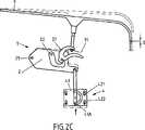
Es zeigenShow it
An der Klappe ist ein Schließbolzen
Das Schloss
Der Antrieb
Demzufolge wird in
In
Abweichend von
Auf besonders einfachere Weise kann man mittels dieses Aufbaus erreichen, dass sich die Motoreinheit
Nach Erreichen dieses Anschlags aus
Auch hier sind Befestigungsmittel denkbar, die nach dem Prinzip von Rasten, insbesondere Einwegrasten, funktionieren: Diese Rasten fixieren zum Zweck des Justierens die Motoreinheit ausreichend, damit die Motoreinheit auf dem Weg zum Motorendanschlag den Türspalt oder Haubenspalt verringern kann, bis der Türspalt oder Haubenspalt einen Anschlag bildet. Die Rasten sind aber nachgiebig genug, damit die Motoreinheit ausreichend beweglich ist, damit nach Erreichen des Anschlags die Motoreinheit bis zum Erreichen des Motorendanschlags verfahren kann, während sich die Motoreinheit zum Ausgleich relativ zum Träger bewegen kann. Dazu sind Einwegrasten bevorzugt, die lediglich diese Bewegungsrichtung zulassen.Here, too, fastening means are conceivable which function according to the principle of detents, in particular disposable pegs: These catches fix the motor unit sufficiently for the purpose of adjustment so that the motor unit can reduce the door gap or hood gap on the way to the motor end stop until the door gap or hood gap Stop forms. However, the detents are compliant enough for the motor unit to be sufficiently mobile to allow the motor unit to negotiate upon reaching the stop until the motor end stop is reached, while the motor unit can move relative to the carrier to compensate. For this purpose Einwegrasten are preferred that allow only this direction of movement.
Abweichend von
BezugszeichenlisteLIST OF REFERENCE NUMBERS
- 11
- Schließvorrichtungclosing device
- 22
- Schlosslock
- 2121
- Drehfallecatch
- 2222
- Sperrklinkepawl
- 2929
- Drehachse SchlossRotary axis lock
- 33
- Türe oder KlappeDoor or flap
- 3131
- Schließbolzenlocking pin
- 44
- Antriebdrive
- 4141
- Motoreinheitmotor unit
- 4242
- Befestigungsmittel für MotoreinheitFastener for motor unit
- 421421
- Schraube/MutterBolt / nut
- 422422
- Bohrung/LanglochHole / slot
- 55
- Sensorsensor
- 5151
- Stellmittel, nämlich RastenAdjusting means, namely notches
- 5252
- Stellmittel, nämlich GegenrasteAdjusting means, namely counter-locking
- 5959
- Drehachse SensorRotary axis sensor
ZITATE ENTHALTEN IN DER BESCHREIBUNG QUOTES INCLUDE IN THE DESCRIPTION
Diese Liste der vom Anmelder aufgeführten Dokumente wurde automatisiert erzeugt und ist ausschließlich zur besseren Information des Lesers aufgenommen. Die Liste ist nicht Bestandteil der deutschen Patent- bzw. Gebrauchsmusteranmeldung. Das DPMA übernimmt keinerlei Haftung für etwaige Fehler oder Auslassungen.This list of the documents listed by the applicant has been generated automatically and is included solely for the better information of the reader. The list is not part of the German patent or utility model application. The DPMA assumes no liability for any errors or omissions.
Zitierte PatentliteraturCited patent literature
- DE 102009026921 A1[0009]DE 102009026921 A1[0009]
- DE 102008005181 A1[0010]DE 102008005181 A1[0010]
- DE 10033092 A1[0010]DE 10033092 A1[0010]
- DE 102004011798 B3[0010]DE 102004011798 B3[0010]
- DE 102004013671 A1[0010]DE 102004013671 A1[0010]
- EP 1489252 B1[0013, 0014]EP 1489252 B1[0013, 0014]
- DE 102013109051[0016, 0016]DE 102013109051[0016, 0016]
Claims (12)
Translated fromGermanPriority Applications (2)
| Application Number | Priority Date | Filing Date | Title |
|---|---|---|---|
| DE102014002580.2ADE102014002580A1 (en) | 2014-02-26 | 2014-02-26 | Closing device for a motor vehicle hood |
| PCT/DE2015/000064WO2015127917A2 (en) | 2014-02-26 | 2015-02-12 | Closing device for a motor vehicle hood |
Applications Claiming Priority (1)
| Application Number | Priority Date | Filing Date | Title |
|---|---|---|---|
| DE102014002580.2ADE102014002580A1 (en) | 2014-02-26 | 2014-02-26 | Closing device for a motor vehicle hood |
Publications (1)
| Publication Number | Publication Date |
|---|---|
| DE102014002580A1true DE102014002580A1 (en) | 2015-08-27 |
Family
ID=52807466
Family Applications (1)
| Application Number | Title | Priority Date | Filing Date |
|---|---|---|---|
| DE102014002580.2APendingDE102014002580A1 (en) | 2014-02-26 | 2014-02-26 | Closing device for a motor vehicle hood |
Country Status (2)
| Country | Link |
|---|---|
| DE (1) | DE102014002580A1 (en) |
| WO (1) | WO2015127917A2 (en) |
Cited By (2)
| Publication number | Priority date | Publication date | Assignee | Title |
|---|---|---|---|---|
| US20170089103A1 (en)* | 2015-09-29 | 2017-03-30 | Magna Closures S.P.A. | One motor latch assembly with power cinch and power release having soft opening function |
| US20170096845A1 (en)* | 2014-04-30 | 2017-04-06 | Kiekert Aktiengesellschaft | Closing device for a motor-vehicle hood, and method |
Families Citing this family (1)
| Publication number | Priority date | Publication date | Assignee | Title |
|---|---|---|---|---|
| CN116332830A (en) | 2021-12-23 | 2023-06-27 | 苏州艾博生物科技有限公司 | Lipid compounds and lipid nanoparticle compositions |
Citations (14)
| Publication number | Priority date | Publication date | Assignee | Title |
|---|---|---|---|---|
| DE3721962A1 (en)* | 1987-07-03 | 1989-01-12 | Kiekert Gmbh Co Kg | Door fastening for a motor-vehicle door |
| US5222775A (en)* | 1991-03-29 | 1993-06-29 | Ohi Seisakusho Co., Ltd. | Power operated latch device for automotive back door |
| US5411302A (en)* | 1992-06-29 | 1995-05-02 | Ohi Seisakusho Co., Ltd. | Powered closing device |
| DE19530725A1 (en)* | 1995-08-18 | 1997-02-20 | Kiekert Ag | Alignment of vehicle door and door lock in door frame |
| DE10033092A1 (en) | 2000-07-07 | 2002-01-24 | Siemens Ag | Rectifier IGBT circuit with several IGBTs in series comprises reverse feed diode for disposing of discharge energy of switching capacitor to storage capacitor on switch-on of IGBT |
| DE10128608A1 (en)* | 2001-06-13 | 2003-07-03 | Valeo Sicherheitssysteme Gmbh | Locking aid for locking a vehicle door |
| DE10218915A1 (en)* | 2002-04-27 | 2003-11-20 | Huf Huelsbeck & Fuerst Gmbh | Actuators for closures on vehicles |
| DE102004011798B3 (en) | 2004-03-11 | 2005-10-13 | Huf Hülsbeck & Fürst Gmbh & Co. Kg | Power operated automotive lock for door has a powered combined closing/opening aid incorporating a gear for two output components |
| DE102004013671A1 (en) | 2004-03-19 | 2005-10-20 | Huf Huelsbeck & Fuerst Gmbh | Lock, in particular for vehicle doors, flaps o. The like. |
| DE102006028570A1 (en)* | 2006-06-22 | 2007-12-27 | Audi Ag | Locking clamp arrangement for locking device of e.g. automobile, has locking clamp fastened at front hood of automobile via retaining component, where clamp is adjusted opposite to retaining component and is fixed in adjusted position |
| DE102008005181A1 (en) | 2008-01-19 | 2009-07-23 | Huf Hülsbeck & Fürst Gmbh & Co. Kg | Locking aid for pulling up e.g. door, at vehicle body, has securing unit set inactive, when locking element is engaged by locking unit and motor-driven movement of locking element begins and continues up to end position of locking element |
| DE102009026921A1 (en) | 2009-06-12 | 2010-12-16 | Kiekert Ag | Motor vehicle lock with closing aid |
| EP1489252B1 (en) | 2003-06-18 | 2012-12-19 | Kiekert Aktiengesellschaft | Motor vehicle door lock |
| DE102013109051A1 (en) | 2013-08-21 | 2015-02-26 | Kiekert Aktiengesellschaft | Motor vehicle door lock |
Family Cites Families (4)
| Publication number | Priority date | Publication date | Assignee | Title |
|---|---|---|---|---|
| US2943880A (en)* | 1958-07-30 | 1960-07-05 | Gen Motors Corp | Closure latch |
| US3378291A (en)* | 1966-04-25 | 1968-04-16 | Gen Motors Corp | Closure latch |
| US4861089A (en)* | 1988-08-29 | 1989-08-29 | General Motors Corporation | Vehicle venting arrangement responsive to side door opening and closing |
| DE102009018188B4 (en)* | 2009-04-22 | 2017-09-07 | BÖCO Böddecker & Co. GmbH & Co. KG | Device for automatically closing a vehicle door |
- 2014
- 2014-02-26DEDE102014002580.2Apatent/DE102014002580A1/enactivePending
- 2015
- 2015-02-12WOPCT/DE2015/000064patent/WO2015127917A2/enactiveApplication Filing
Patent Citations (14)
| Publication number | Priority date | Publication date | Assignee | Title |
|---|---|---|---|---|
| DE3721962A1 (en)* | 1987-07-03 | 1989-01-12 | Kiekert Gmbh Co Kg | Door fastening for a motor-vehicle door |
| US5222775A (en)* | 1991-03-29 | 1993-06-29 | Ohi Seisakusho Co., Ltd. | Power operated latch device for automotive back door |
| US5411302A (en)* | 1992-06-29 | 1995-05-02 | Ohi Seisakusho Co., Ltd. | Powered closing device |
| DE19530725A1 (en)* | 1995-08-18 | 1997-02-20 | Kiekert Ag | Alignment of vehicle door and door lock in door frame |
| DE10033092A1 (en) | 2000-07-07 | 2002-01-24 | Siemens Ag | Rectifier IGBT circuit with several IGBTs in series comprises reverse feed diode for disposing of discharge energy of switching capacitor to storage capacitor on switch-on of IGBT |
| DE10128608A1 (en)* | 2001-06-13 | 2003-07-03 | Valeo Sicherheitssysteme Gmbh | Locking aid for locking a vehicle door |
| DE10218915A1 (en)* | 2002-04-27 | 2003-11-20 | Huf Huelsbeck & Fuerst Gmbh | Actuators for closures on vehicles |
| EP1489252B1 (en) | 2003-06-18 | 2012-12-19 | Kiekert Aktiengesellschaft | Motor vehicle door lock |
| DE102004011798B3 (en) | 2004-03-11 | 2005-10-13 | Huf Hülsbeck & Fürst Gmbh & Co. Kg | Power operated automotive lock for door has a powered combined closing/opening aid incorporating a gear for two output components |
| DE102004013671A1 (en) | 2004-03-19 | 2005-10-20 | Huf Huelsbeck & Fuerst Gmbh | Lock, in particular for vehicle doors, flaps o. The like. |
| DE102006028570A1 (en)* | 2006-06-22 | 2007-12-27 | Audi Ag | Locking clamp arrangement for locking device of e.g. automobile, has locking clamp fastened at front hood of automobile via retaining component, where clamp is adjusted opposite to retaining component and is fixed in adjusted position |
| DE102008005181A1 (en) | 2008-01-19 | 2009-07-23 | Huf Hülsbeck & Fürst Gmbh & Co. Kg | Locking aid for pulling up e.g. door, at vehicle body, has securing unit set inactive, when locking element is engaged by locking unit and motor-driven movement of locking element begins and continues up to end position of locking element |
| DE102009026921A1 (en) | 2009-06-12 | 2010-12-16 | Kiekert Ag | Motor vehicle lock with closing aid |
| DE102013109051A1 (en) | 2013-08-21 | 2015-02-26 | Kiekert Aktiengesellschaft | Motor vehicle door lock |
Cited By (4)
| Publication number | Priority date | Publication date | Assignee | Title |
|---|---|---|---|---|
| US20170096845A1 (en)* | 2014-04-30 | 2017-04-06 | Kiekert Aktiengesellschaft | Closing device for a motor-vehicle hood, and method |
| US10094148B2 (en)* | 2014-04-30 | 2018-10-09 | Kiekert Aktiengesellschaft | Closing device for a motor-vehicle hood, and method |
| US20170089103A1 (en)* | 2015-09-29 | 2017-03-30 | Magna Closures S.P.A. | One motor latch assembly with power cinch and power release having soft opening function |
| US11162284B2 (en)* | 2015-09-29 | 2021-11-02 | Magna Closures S.P.A. | One motor latch assembly with power cinch and power release having soft opening function |
Also Published As
| Publication number | Publication date |
|---|---|
| WO2015127917A2 (en) | 2015-09-03 |
| WO2015127917A3 (en) | 2015-10-15 |
Similar Documents
| Publication | Publication Date | Title |
|---|---|---|
| EP3036390B1 (en) | Motor vehicle door lock | |
| EP3699379B1 (en) | Motor vehicle lock | |
| EP3087237B1 (en) | Locking device for a vehicle hood and process | |
| DE102014119382A1 (en) | Motor vehicle lock arrangement | |
| DE102009021297A1 (en) | Motor vehicle lock | |
| EP3271539B1 (en) | Motor vehicle door | |
| DE102004010294A1 (en) | Tank recess for automobiles | |
| WO2015113547A1 (en) | Closing device for a motor-vehicle hood, and method | |
| EP2492423A2 (en) | Barrier with opening trends | |
| DE102017124525A1 (en) | Motor vehicle door lock | |
| EP2436859A2 (en) | Motor vehicle lock | |
| DE10361168B4 (en) | Motor vehicle lock, in particular for hoods or flaps | |
| DE102017216920A1 (en) | Door handle device for a door of a motor vehicle, door, motor vehicle | |
| DE202015100809U1 (en) | Motor vehicle lock | |
| DE19634898C2 (en) | Device for closing and closing as well as opening the tailgate of a motor vehicle | |
| DE102014002580A1 (en) | Closing device for a motor vehicle hood | |
| EP3196393A1 (en) | Internal pivoting door assembly with over dead point locking device | |
| DE102008024341A1 (en) | Door-actuating device for use in door, particularly motor vehicle door, comprises door handle, electrical actuator and emergency opening device for lock of door, particularly motor vehicle door | |
| EP1772577A2 (en) | Motor vehicle lock | |
| DE102013222053A1 (en) | Locking device for a motor vehicle hood and method | |
| WO2017220078A1 (en) | Motor vehicle locking system | |
| EP2257441A1 (en) | Motor vehicle door | |
| DE102018121382A1 (en) | Drive unit for automotive applications | |
| DE102014117330A1 (en) | Closing device for a hood, flap or door | |
| EP1849940A2 (en) | Locking device for a sliding door with means for blocking the door in open position |
Legal Events
| Date | Code | Title | Description |
|---|---|---|---|
| R163 | Identified publications notified | ||
| R012 | Request for examination validly filed | ||
| R016 | Response to examination communication |