DE102013226912A1 - gas valve - Google Patents
gas valveDownload PDFInfo
- Publication number
- DE102013226912A1 DE102013226912A1DE102013226912.9ADE102013226912ADE102013226912A1DE 102013226912 A1DE102013226912 A1DE 102013226912A1DE 102013226912 ADE102013226912 ADE 102013226912ADE 102013226912 A1DE102013226912 A1DE 102013226912A1
- Authority
- DE
- Germany
- Prior art keywords
- valve
- valve plate
- gas
- holes
- flow
- Prior art date
- Legal status (The legal status is an assumption and is not a legal conclusion. Google has not performed a legal analysis and makes no representation as to the accuracy of the status listed.)
- Withdrawn
Links
Images


Classifications
- F—MECHANICAL ENGINEERING; LIGHTING; HEATING; WEAPONS; BLASTING
- F16—ENGINEERING ELEMENTS AND UNITS; GENERAL MEASURES FOR PRODUCING AND MAINTAINING EFFECTIVE FUNCTIONING OF MACHINES OR INSTALLATIONS; THERMAL INSULATION IN GENERAL
- F16K—VALVES; TAPS; COCKS; ACTUATING-FLOATS; DEVICES FOR VENTING OR AERATING
- F16K31/00—Actuating devices; Operating means; Releasing devices
- F16K31/02—Actuating devices; Operating means; Releasing devices electric; magnetic
- F16K31/06—Actuating devices; Operating means; Releasing devices electric; magnetic using a magnet, e.g. diaphragm valves, cutting off by means of a liquid
- F16K31/0644—One-way valve
- F16K31/0655—Lift valves
- F—MECHANICAL ENGINEERING; LIGHTING; HEATING; WEAPONS; BLASTING
- F02—COMBUSTION ENGINES; HOT-GAS OR COMBUSTION-PRODUCT ENGINE PLANTS
- F02M—SUPPLYING COMBUSTION ENGINES IN GENERAL WITH COMBUSTIBLE MIXTURES OR CONSTITUENTS THEREOF
- F02M21/00—Apparatus for supplying engines with non-liquid fuels, e.g. gaseous fuels stored in liquid form
- F02M21/02—Apparatus for supplying engines with non-liquid fuels, e.g. gaseous fuels stored in liquid form for gaseous fuels
- F02M21/0218—Details on the gaseous fuel supply system, e.g. tanks, valves, pipes, pumps, rails, injectors or mixers
- F02M21/0248—Injectors
- F02M21/0257—Details of the valve closing elements, e.g. valve seats, stems or arrangement of flow passages
- F02M21/026—Lift valves, i.e. stem operated valves
- F02M21/0263—Inwardly opening single or multi nozzle valves, e.g. needle valves
- F—MECHANICAL ENGINEERING; LIGHTING; HEATING; WEAPONS; BLASTING
- F16—ENGINEERING ELEMENTS AND UNITS; GENERAL MEASURES FOR PRODUCING AND MAINTAINING EFFECTIVE FUNCTIONING OF MACHINES OR INSTALLATIONS; THERMAL INSULATION IN GENERAL
- F16K—VALVES; TAPS; COCKS; ACTUATING-FLOATS; DEVICES FOR VENTING OR AERATING
- F16K1/00—Lift valves or globe valves, i.e. cut-off apparatus with closure members having at least a component of their opening and closing motion perpendicular to the closing faces
- F16K1/32—Details
- F16K1/34—Cutting-off parts, e.g. valve members, seats
- F16K1/36—Valve members
- F—MECHANICAL ENGINEERING; LIGHTING; HEATING; WEAPONS; BLASTING
- F16—ENGINEERING ELEMENTS AND UNITS; GENERAL MEASURES FOR PRODUCING AND MAINTAINING EFFECTIVE FUNCTIONING OF MACHINES OR INSTALLATIONS; THERMAL INSULATION IN GENERAL
- F16K—VALVES; TAPS; COCKS; ACTUATING-FLOATS; DEVICES FOR VENTING OR AERATING
- F16K47/00—Means in valves for absorbing fluid energy
- F16K47/04—Means in valves for absorbing fluid energy for decreasing pressure or noise level, the throttle being incorporated in the closure member
- Y—GENERAL TAGGING OF NEW TECHNOLOGICAL DEVELOPMENTS; GENERAL TAGGING OF CROSS-SECTIONAL TECHNOLOGIES SPANNING OVER SEVERAL SECTIONS OF THE IPC; TECHNICAL SUBJECTS COVERED BY FORMER USPC CROSS-REFERENCE ART COLLECTIONS [XRACs] AND DIGESTS
- Y02—TECHNOLOGIES OR APPLICATIONS FOR MITIGATION OR ADAPTATION AGAINST CLIMATE CHANGE
- Y02T—CLIMATE CHANGE MITIGATION TECHNOLOGIES RELATED TO TRANSPORTATION
- Y02T10/00—Road transport of goods or passengers
- Y02T10/10—Internal combustion engine [ICE] based vehicles
- Y02T10/30—Use of alternative fuels, e.g. biofuels
- Y—GENERAL TAGGING OF NEW TECHNOLOGICAL DEVELOPMENTS; GENERAL TAGGING OF CROSS-SECTIONAL TECHNOLOGIES SPANNING OVER SEVERAL SECTIONS OF THE IPC; TECHNICAL SUBJECTS COVERED BY FORMER USPC CROSS-REFERENCE ART COLLECTIONS [XRACs] AND DIGESTS
- Y10—TECHNICAL SUBJECTS COVERED BY FORMER USPC
- Y10T—TECHNICAL SUBJECTS COVERED BY FORMER US CLASSIFICATION
- Y10T137/00—Fluid handling
- Y10T137/8593—Systems
- Y10T137/86493—Multi-way valve unit
- Y10T137/86879—Reciprocating valve unit
Landscapes
- Engineering & Computer Science (AREA)
- General Engineering & Computer Science (AREA)
- Mechanical Engineering (AREA)
- Chemical & Material Sciences (AREA)
- Chemical Kinetics & Catalysis (AREA)
- General Chemical & Material Sciences (AREA)
- Oil, Petroleum & Natural Gas (AREA)
- Combustion & Propulsion (AREA)
- Lift Valve (AREA)
Abstract
Translated fromGermanDescription
Translated fromGermanDie Erfindung betrifft ein Gasventil, wie es zur Brennstoffversorgung von Wärmekraftmaschinen Verwendung findet.The invention relates to a gas valve, as it finds use for supplying fuel to heat engines.
Stand der TechnikState of the art
Wärmekraftmaschinen, die mit gasförmigen Brennstoffen betrieben werden, benötigen zur Dosierung des Gases Einblasventile oder Zumessventile, die die für jeden Arbeitstackt notwendige Gasmenge in den Zustrom der Luft eindüsen oder ggf. auch direkt in den Brennraum einbringen. Solche Motoren werden häufig als Stationärmotoren eingesetzt, die der Stromerzeugung dienen. Die Ventile können dabei für jeden einzelnen Zylinder separat eingesetzt werden oder in einer zentralen Einblaseinheit für mehrere oder alle Motorzylinder. Ein solches Gasventil ist beispielsweise aus der Schrift
Die Gasventile haben die Aufgabe, in der zur Verfügung stehenden Zeit einen entsprechenden Ventilquerschnitt zu öffnen und das zur Eindüsung vorgesehene Gas unter Zuströmdruck in den Ansaugtrakt zu fördern, in dem ein gewisser Ansaugdruck herrscht. Die Druckdifferenz ist dabei positiv, d. h. dass der Zuströmdruck des Gases höher als der Druck im Ansaugtrakt ist, sodass das Gas bei geöffnetem Gasventil ohne weitere Maßnahmen in den Ansaugtrakt einströmt. Die Menge des eingeblasenen Gases hängt aber im Wesentlichen von der Druckdifferenz und der Öffnungsdauer des Ventils ab. Zur Steuerung der eingedüsten Gasmenge wird dabei zumeist die Ansteuerdauer des Gasventils durch entsprechende Bestromung des in der Regel elektromagnetischen Aktors variiert. Wichtig für den Betrieb der Wärmekraftmaschinen ist dabei ein homogenes Brennstoff-Luft-Gemisch im Zylinder. Da die Motoren häufig bei extremem Magerbetrieb betrieben werden, sind die Anforderungen an die Gemischbildung hoch, um eine gleichmäßige Verbrennung und die optimale Flammgeschwindigkeit zu erreichen. Häufig erfolgt die homogene Gemischbildung des gasförmigen Brennstoffs mit der Luft über die Strömungsführung auf dem Weg bis in den Brennraum.The purpose of the gas valves is to open a corresponding valve cross section in the available time and to supply the gas intended for injection under inflow pressure into the intake tract in which a certain suction pressure prevails. The pressure difference is positive, d. H. that the inflow pressure of the gas is higher than the pressure in the intake tract, so that the gas flows into the intake tract with the gas valve open without further measures. However, the amount of injected gas depends essentially on the pressure difference and the opening duration of the valve. To control the injected gas quantity, the activation duration of the gas valve is usually varied by appropriate energization of the electromagnetic actuator, as a rule. Important for the operation of heat engines is a homogeneous fuel-air mixture in the cylinder. Since the engines are often operated in extreme lean operation, the requirements for mixture formation are high, in order to achieve a uniform combustion and the optimum flame speed. Frequently, the homogeneous mixture formation of the gaseous fuel with the air via the flow guide on the way to the combustion chamber.
Bei den heute bekannten Ventilen werden Flachsitze verwendet, die einen oder mehrere ringförmige Spalte freigeben. Diese Ringe werden über Stege zusammengehalten. Dadurch ergeben sich über den Radius Steifigkeitssprünge und über den Umfang unregelmäßige Steifigkeiten von Ventilplatte und Ventilteller, was zu Undichtigkeiten des Ventils im geschlossenen Zustand führen kann. Die Vermeidung dieser Unregelmäßigkeiten in der Steifigkeit durch Variation von Form und Anzahl der Stege ist aufwändig und verteuert das Gasventil und damit den mit der Wärmekraftmaschine erzeugten Strom.In the valves known today flat seats are used, which release one or more annular gaps. These rings are held together by webs. This results in over the radius stiffness jumps and over the circumference irregular stiffness of valve plate and valve disc, which can lead to leaks of the valve in the closed state. The avoidance of these irregularities in the rigidity by varying the shape and number of webs is complex and expensive the gas valve and thus the power generated by the heat engine.
Vorteile der ErfindungAdvantages of the invention
Das erfindungsgemäße Gasventil zur Brennstoffversorgung von Wärmekraftmaschinen weist demgegenüber den Vorteil auf, dass es über eine hohe mechanische Stabilität und damit eine gute Dichtigkeit verfügt bei gleichzeitig geringen Herstellungskosten. Dazu weist das Gasventil zur Brennstoffversorgung der Wärmekraftmaschine eine Ventilplatte auf, in der Strömungsbohrungen zur Durchleitung des zu steuernden Gasstromes ausgebildet sind. Ein Ventilteller ist dabei längsbeweglich im Gasventil angeordnet, der mit der Ventilplatte zum Öffnen und Schließen der Strömungsbohrungen zusammenwirkt, wobei im Ventilteller Bohrungen für den zu steuernden Gasstrom ausgebildet sind. Die Strömungsbohrungen der Ventilplatte sind als Bohrungen mit kreisrundem Querschnitt ausgebildet.The gas valve according to the invention for supplying fuel to heat engines has the advantage that it has a high mechanical stability and thus a good tightness with low production costs. For this purpose, the gas valve for supplying fuel to the heat engine on a valve plate, are formed in the flow holes for the passage of the gas flow to be controlled. A valve disk is arranged longitudinally movably in the gas valve, which cooperates with the valve plate for opening and closing the flow bores, wherein bores for the gas flow to be controlled are formed in the valve disk. The flow holes of the valve plate are formed as holes with a circular cross-section.
Durch die Ausbildung der Bohrungen anstelle der Stege mit den dazwischen ausgebildeten Schlitzen zur Durchleitung des Gases kann die Ventilplatte sehr stabil hergestellt werden. Über die Anzahl und Größe der Bohrungen kann leicht der Durchströmquerschnitt variiert werden und damit ein großer Durchströmquerschnitt schnell geschaltet werden. Die Bohrungen weisen darüber hinaus den Vorteil auf, dass eine sehr homogene Verteilung des Gases stromabwärts des Gasventils erfolgt, was für eine optimale Verbrennung im Brennraum der entsprechenden Wärmekraftmaschine günstig ist.By forming the holes instead of the webs with the slots formed therebetween for the passage of the gas, the valve plate can be made very stable. About the number and size of the holes can easily be varied in the flow area and thus a large flow area are quickly switched. The bores also have the advantage that a very homogeneous distribution of the gas takes place downstream of the gas valve, which is favorable for optimal combustion in the combustion chamber of the corresponding heat engine.
In einer ersten vorteilhaften Ausgestaltung der Erfindung ist die Ventilplatte zumindest im Wesentlichen scheibenförmig ausgebildet und weist eine obere und untere Stirnfläche auf, die parallel zueinander ausgerichtet sind. Die Strömungsbohrungen sind senkrecht zur Stirnfläche der Ventilplatte ausgerichtet, wobei die Ventilplatte vorteilhafterweise ortsfest innerhalb des Gehäuses des Gasventils eingespannt ist. Durch diese Anordnung der Bohrungen in der Ventilplatte lässt sich die maximale Anzahl von Bohrungen unterbringen bei gleichzeitig optimierter Stabilität.In a first advantageous embodiment of the invention, the valve plate is at least substantially disc-shaped and has an upper and lower end face, which are aligned parallel to each other. The flow holes are aligned perpendicular to the end face of the valve plate, wherein the valve plate is advantageously clamped stationary within the housing of the gas valve. This arrangement of the holes in the valve plate can accommodate the maximum number of holes while optimized stability.
In einer weiteren vorteilhaften Ausgestaltung sind auch die Bohrungen im Ventilteller als Bohrungen mit kreisrundem Querschnitt ausgebildet. Dabei sind die Bohrungen des Ventiltellers und der Ventilplatte in vorteilhafter Weise so angeordnet, dass sie sich im geschlossenen Zustand des Gasventils nicht überdecken. Sind darüber hinaus in vorteilhafter Weise zwischen den Bohrungen der Ventilplatte bzw. des Ventiltellers Dichtbereiche ausgebildet, die zum Abdichten der Strömungsbohrungen zusammenwirken, so erreicht das Gasventil eine hohe Dichtigkeit mit nur minimalen Leckageströmen. In a further advantageous embodiment, the holes in the valve disk are formed as holes with a circular cross-section. The holes of the valve disk and the valve plate are advantageously arranged so that they do not overlap in the closed state of the gas valve. Are also formed in an advantageous manner between the bores of the valve plate or the valve disk sealing regions which cooperate to seal the flow holes, the gas valve reaches a high density with minimal leakage currents.
In einer weiteren vorteilhaften Ausgestaltung ist der Ventilteller zumindest im Wesentlichen kreisscheibenförmig ausgebildet und die Bohrungen im Ventilteller sind in Lochkreisen angeordnet, die um das Zentrum des Ventiltellers ausgebildet sind. Die gleiche Anordnung von Bohrungen kann auch in der Ventilplatte vorgesehen sein, wobei auch hier die Lochkreise um das Zentrum einer im Wesentlichen kreisscheibenförmigen Ventilplatte ausgebildet sind. Diese Anordnung der Bohrungen kann auf entsprechenden Bohrmaschinen einfach hergestellt werden und erlaubt eine dichte Anordnung der Bohrungen.In a further advantageous embodiment, the valve disk is at least substantially circular disk-shaped and the holes in the valve disk are arranged in hole circles which are formed around the center of the valve disk. The same arrangement of holes can also be provided in the valve plate, wherein also here the hole circles are formed around the center of a substantially circular disk-shaped valve plate. This arrangement of the holes can be easily made on appropriate drills and allows a dense arrangement of the holes.
In einer weiteren vorteilhaften Ausgestaltung weisen die Bohrungen im Ventilteller nicht alle den gleichen Durchmesser auf. Ebenso können die Strömungsbohrungen in der Ventilplatte nicht alle den gleichen Durchmesser aufweisen. Durch die verschiedenen Bohrungsdurchmesser kann zum einen eine dichtere Packung der Bohrungen bei gleichzeitig ausreichend stabilen Stegen zwischen den Bohrungen erreicht werden. Zum anderen kann dadurch eine optimale Anpassung der Strömung stromabwärts des Gasventils erreicht werden.In a further advantageous embodiment, the holes in the valve disc not all the same diameter. Likewise, the flow holes in the valve plate may not all be the same diameter. Due to the different bore diameters, on the one hand, a denser packing of the bores can be achieved with sufficiently stable webs between the bores. On the other hand, an optimal adaptation of the flow downstream of the gas valve can be achieved.
Die Bohrungen, die im Ventilteller und/oder in der Ventilplatte ausgebildet sind, weisen einen kreisrunden Durchmesser auf, sodass sie durch einen einfachen Bohrprozess herstellbar sind.The holes that are formed in the valve plate and / or in the valve plate, have a circular diameter, so that they can be produced by a simple drilling process.
Zeichnungdrawing
In der Zeichnung ist ein erfindungsgemäßes Gasventil dargestellt. Es zeigt dieIn the drawing, an inventive gas valve is shown. It shows the
Beschreibung der AusführungsbeispieleDescription of the embodiments
In
Der Ventilplatte
Zur Durchströmung des Gases aus dem Gasraum
Der nähere Aufbau des Ventiltellers
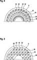
In
Die Bohrungen
In
Die Bohrungen
ZITATE ENTHALTEN IN DER BESCHREIBUNG QUOTES INCLUDE IN THE DESCRIPTION
Diese Liste der vom Anmelder aufgeführten Dokumente wurde automatisiert erzeugt und ist ausschließlich zur besseren Information des Lesers aufgenommen. Die Liste ist nicht Bestandteil der deutschen Patent- bzw. Gebrauchsmusteranmeldung. Das DPMA übernimmt keinerlei Haftung für etwaige Fehler oder Auslassungen.This list of the documents listed by the applicant has been generated automatically and is included solely for the better information of the reader. The list is not part of the German patent or utility model application. The DPMA assumes no liability for any errors or omissions.
Zitierte PatentliteraturCited patent literature
- US 6182943 B1[0002]US 6182943 B1[0002]
Claims (9)
Translated fromGermanPriority Applications (2)
| Application Number | Priority Date | Filing Date | Title |
|---|---|---|---|
| DE102013226912.9ADE102013226912A1 (en) | 2013-12-20 | 2013-12-20 | gas valve |
| US14/578,498US20150176714A1 (en) | 2013-12-20 | 2014-12-22 | Gas valve |
Applications Claiming Priority (1)
| Application Number | Priority Date | Filing Date | Title |
|---|---|---|---|
| DE102013226912.9ADE102013226912A1 (en) | 2013-12-20 | 2013-12-20 | gas valve |
Publications (1)
| Publication Number | Publication Date |
|---|---|
| DE102013226912A1true DE102013226912A1 (en) | 2015-06-25 |
Family
ID=53275221
Family Applications (1)
| Application Number | Title | Priority Date | Filing Date |
|---|---|---|---|
| DE102013226912.9AWithdrawnDE102013226912A1 (en) | 2013-12-20 | 2013-12-20 | gas valve |
Country Status (2)
| Country | Link |
|---|---|
| US (1) | US20150176714A1 (en) |
| DE (1) | DE102013226912A1 (en) |
Cited By (1)
| Publication number | Priority date | Publication date | Assignee | Title |
|---|---|---|---|---|
| DE102016215231A1 (en)* | 2016-08-16 | 2018-02-22 | Robert Bosch Gmbh | Valve for metering gaseous fuel |
Citations (1)
| Publication number | Priority date | Publication date | Assignee | Title |
|---|---|---|---|---|
| US6182943B1 (en) | 1998-02-24 | 2001-02-06 | Hoerbiger Ventilwerke Gmbh | Gas valve with electromagnetic actuation |
Family Cites Families (7)
| Publication number | Priority date | Publication date | Assignee | Title |
|---|---|---|---|---|
| US957012A (en)* | 1907-09-19 | 1910-05-03 | James Stone | Valve. |
| US4538642A (en)* | 1984-04-20 | 1985-09-03 | Eaton Corporation | Fast acting valve |
| US5398724A (en)* | 1993-06-28 | 1995-03-21 | Woodward Governor Company | High speed electrically actuated gaseous fuel admission valve |
| US6112765A (en)* | 1998-05-26 | 2000-09-05 | Caterpillar Inc. | Method and apparatus for monitoring operation of a gaseous fuel admission valve |
| US6527194B1 (en)* | 2000-10-06 | 2003-03-04 | Donald Burke | Flow control damper |
| US7625624B2 (en)* | 2004-04-30 | 2009-12-01 | E.I. Du Pont De Nemours And Company | Adaptive membrane structure with insertable protrusions |
| US8272399B2 (en)* | 2008-06-13 | 2012-09-25 | Woodward, Inc. | Fluid admission system for providing a pressure-balanced valve |
- 2013
- 2013-12-20DEDE102013226912.9Apatent/DE102013226912A1/ennot_activeWithdrawn
- 2014
- 2014-12-22USUS14/578,498patent/US20150176714A1/ennot_activeAbandoned
Patent Citations (1)
| Publication number | Priority date | Publication date | Assignee | Title |
|---|---|---|---|---|
| US6182943B1 (en) | 1998-02-24 | 2001-02-06 | Hoerbiger Ventilwerke Gmbh | Gas valve with electromagnetic actuation |
Cited By (2)
| Publication number | Priority date | Publication date | Assignee | Title |
|---|---|---|---|---|
| DE102016215231A1 (en)* | 2016-08-16 | 2018-02-22 | Robert Bosch Gmbh | Valve for metering gaseous fuel |
| DE102016215231B4 (en) | 2016-08-16 | 2024-06-20 | Robert Bosch Gmbh | Valve for metering gaseous fuel |
Also Published As
| Publication number | Publication date |
|---|---|
| US20150176714A1 (en) | 2015-06-25 |
Similar Documents
| Publication | Publication Date | Title |
|---|---|---|
| DE60025090T2 (en) | Injector for gaseous fuel with valve needle seat with low restriction | |
| DE102007044877A1 (en) | Fluid injection valve | |
| DE19905721A1 (en) | Electromagnetically actuated gas valve for use as a fuel injection valve in a gas engine | |
| EP2818679B1 (en) | Method and device for injecting a gaseous medium | |
| DE102007008901B4 (en) | Fluid injection valve | |
| DE102020203194B4 (en) | INTERNAL COMBUSTION ENGINE FOR OPERATION WITH GASEOUS FUEL, ESPECIALLY HYDROGEN, AND HIGH-PRESSURE VALVE FOR INTRODUCING GASEOUS FUEL INTO THE INTERNAL COMBUSTION ENGINE | |
| DE1476146B2 (en) | Electromagnetically operated fuel injector for internal combustion engines. Änm: Associated Engineering Ltd., Leamington Spa, Warwickshire (Great Britain) | |
| DE69921116T2 (en) | ELECTROMAGNET VALVE FOR GAS FLUIDUM | |
| DE102006055548A1 (en) | fuel injector | |
| DE10201307A1 (en) | Electromagnetically operated fuel shut-off valve | |
| WO2021228496A1 (en) | Gas metering valve for internal combustion engines | |
| AT412807B (en) | ELECTROMAGNETICALLY ACTUATED GAS VALVE | |
| DE102006050810A1 (en) | Fuel injector for internal combustion engines, comprises control valve with stationary valve pin which has internal relief duct that extends from control chamber to annular groove of valve pin | |
| DE10334474A1 (en) | High-flow control valve for motor vehicle fuel injection systems | |
| DE102013226912A1 (en) | gas valve | |
| DE102011089360A1 (en) | Fuel injection valve for internal combustion engines | |
| DE4239280C2 (en) | Device for the combined blowing out of fuel and air | |
| DE102007006946A1 (en) | Injector for injecting fuel into combustion chambers of internal combustion engines | |
| DE602004005052T2 (en) | Injection valve for internal combustion engine | |
| DE102021212503A1 (en) | Gaseous fuel injector | |
| DE102015216759A1 (en) | Two-substance injector for two media | |
| EP3464865A1 (en) | Gas valve for dosing gaseous fuels | |
| DE102007001650A1 (en) | Valve e.g. solenoid valve, for use in e.g. internal-combustion engine, has valve unit with flat seat, for releasing and closing opening, where flow direction of gaseous medium through opening is same as actuation direction for opening valve | |
| AT413135B (en) | Electromagnetically actuated gas valve for use as a fuel injection valve in a gas engine | |
| DE60318526T2 (en) | FUEL INJECTION DEVICE FOR A COMBUSTION ENGINE WITH HYDRAULIC PENETRATING |
Legal Events
| Date | Code | Title | Description |
|---|---|---|---|
| R119 | Application deemed withdrawn, or ip right lapsed, due to non-payment of renewal fee |