DE102013225575A1 - Arrangement and method for collision detection and imaging device with an arrangement for collision detection - Google Patents
Arrangement and method for collision detection and imaging device with an arrangement for collision detectionDownload PDFInfo
- Publication number
- DE102013225575A1 DE102013225575A1DE102013225575.6ADE102013225575ADE102013225575A1DE 102013225575 A1DE102013225575 A1DE 102013225575A1DE 102013225575 ADE102013225575 ADE 102013225575ADE 102013225575 A1DE102013225575 A1DE 102013225575A1
- Authority
- DE
- Germany
- Prior art keywords
- housing
- collision
- sensor element
- edge
- tactile sensor
- Prior art date
- Legal status (The legal status is an assumption and is not a legal conclusion. Google has not performed a legal analysis and makes no representation as to the accuracy of the status listed.)
- Granted
Links
- 238000001514detection methodMethods0.000titleclaimsabstractdescription13
- 238000003384imaging methodMethods0.000titleclaimsabstractdescription11
- 238000000034methodMethods0.000titleclaimsabstractdescription9
- 125000006850spacer groupChemical group0.000claimsdescription13
- 238000011156evaluationMethods0.000claimsdescription6
- 239000004753textileSubstances0.000claimsdescription6
- 239000007788liquidSubstances0.000claimsdescription3
- 230000000694effectsEffects0.000abstractdescription2
- 230000002093peripheral effectEffects0.000abstract2
- 239000004744fabricSubstances0.000description4
- 238000011161developmentMethods0.000description2
- 230000018109developmental processEffects0.000description2
- BUHVIAUBTBOHAG-FOYDDCNASA-N(2r,3r,4s,5r)-2-[6-[[2-(3,5-dimethoxyphenyl)-2-(2-methylphenyl)ethyl]amino]purin-9-yl]-5-(hydroxymethyl)oxolane-3,4-diolChemical compoundCOC1=CC(OC)=CC(C(CNC=2C=3N=CN(C=3N=CN=2)[C@H]2[C@@H]([C@H](O)[C@@H](CO)O2)O)C=2C(=CC=CC=2)C)=C1BUHVIAUBTBOHAG-FOYDDCNASA-N0.000description1
- 229920000049Carbon (fiber)Polymers0.000description1
- 239000004917carbon fiberSubstances0.000description1
- 230000001419dependent effectEffects0.000description1
- 238000003745diagnosisMethods0.000description1
- 239000013013elastic materialSubstances0.000description1
- 230000004807localizationEffects0.000description1
- 238000007789sealingMethods0.000description1
- 238000002560therapeutic procedureMethods0.000description1
- 230000001960triggered effectEffects0.000description1
Images


Classifications
- A—HUMAN NECESSITIES
- A61—MEDICAL OR VETERINARY SCIENCE; HYGIENE
- A61B—DIAGNOSIS; SURGERY; IDENTIFICATION
- A61B6/00—Apparatus or devices for radiation diagnosis; Apparatus or devices for radiation diagnosis combined with radiation therapy equipment
- A61B6/10—Safety means specially adapted therefor
- A61B6/102—Protection against mechanical damage, e.g. anti-collision devices
- G—PHYSICS
- G01—MEASURING; TESTING
- G01L—MEASURING FORCE, STRESS, TORQUE, WORK, MECHANICAL POWER, MECHANICAL EFFICIENCY, OR FLUID PRESSURE
- G01L1/00—Measuring force or stress, in general
- G01L1/02—Measuring force or stress, in general by hydraulic or pneumatic means
- A—HUMAN NECESSITIES
- A61—MEDICAL OR VETERINARY SCIENCE; HYGIENE
- A61B—DIAGNOSIS; SURGERY; IDENTIFICATION
- A61B6/00—Apparatus or devices for radiation diagnosis; Apparatus or devices for radiation diagnosis combined with radiation therapy equipment
- A61B6/44—Constructional features of apparatus for radiation diagnosis
- A61B6/4429—Constructional features of apparatus for radiation diagnosis related to the mounting of source units and detector units
- A61B6/4435—Constructional features of apparatus for radiation diagnosis related to the mounting of source units and detector units the source unit and the detector unit being coupled by a rigid structure
- A61B6/4441—Constructional features of apparatus for radiation diagnosis related to the mounting of source units and detector units the source unit and the detector unit being coupled by a rigid structure the rigid structure being a C-arm or U-arm
Landscapes
- Health & Medical Sciences (AREA)
- Life Sciences & Earth Sciences (AREA)
- Medical Informatics (AREA)
- Engineering & Computer Science (AREA)
- Physics & Mathematics (AREA)
- Radiology & Medical Imaging (AREA)
- Heart & Thoracic Surgery (AREA)
- Nuclear Medicine, Radiotherapy & Molecular Imaging (AREA)
- Optics & Photonics (AREA)
- Pathology (AREA)
- Biophysics (AREA)
- Biomedical Technology (AREA)
- High Energy & Nuclear Physics (AREA)
- Molecular Biology (AREA)
- Surgery (AREA)
- Animal Behavior & Ethology (AREA)
- General Health & Medical Sciences (AREA)
- Public Health (AREA)
- Veterinary Medicine (AREA)
- General Physics & Mathematics (AREA)
- Apparatus For Radiation Diagnosis (AREA)
Abstract
Translated fromGermanDescription
Translated fromGermanGebiet der ErfindungField of the invention
Die Erfindung betrifft eine Anordnung und ein Verfahren zur Kollisionserkennung eines Gehäuses mit einem Objekt sowie ein Bildgebungsgerät mit einer derartigen Anordnung.The invention relates to an arrangement and a method for collision detection of a housing with an object and an imaging device with such an arrangement.
Hintergrund der ErfindungBackground of the invention
Ein bildgebendes Röntgengerät ist beispielsweise aus der Patentschrift
Medizintechnische Geräte für die medizinische Diagnose oder Therapie weisen in der Regel einen Röntgenstrahler und einen Röntgendetektor jeweils in einem Gehäuse auf. Diese beiden Komponenten sind in einem Abstand zueinander angeordnet, wobei ein zu untersuchender oder zu behandelnder Patient zwischen dem Röntgenstrahler und dem Röntgendetektor gelagert wird. Der Röntgenstrahler und der Röntgendetektor sind relativ zum Körper des Patienten so positioniert, dass ein Bild des gewünschten Querschnitts des Körperinneren aufgenommen werden kann. Die Ausrichtung und die Positionierung des medizintechnischen Geräts können meist mit Hilfe eines motorischen Antriebs vorgenommen werden.Medical devices for medical diagnosis or therapy usually have an X-ray source and an X-ray detector in each case in a housing. These two components are arranged at a distance to each other, wherein a patient to be examined or treated between the X-ray source and the X-ray detector is stored. The x-ray emitter and the x-ray detector are positioned relative to the body of the patient so that an image of the desired cross-section of the interior of the body can be taken. The alignment and positioning of the medical device can usually be carried out with the aid of a motor drive.
Derartige Geräte sind oftmals mit einem C-Bogen ausgestattet, d.h. einer bogenförmigen Halterung, die mit Hilfe eines Schienensystems um mehrere Ebenen gedreht werden kann. Während der Benutzung des medizintechnischen Geräts ist es wichtig, dass ein bewegtes Teil, zum Beispiel der Röntgendetektor, nahe an das zu untersuchende Objekt herankommt, um die gewünschte Bildqualität zu erreichen. Der Röntgendetektor hat eine vergleichsweise große Frontfläche zum Empfangen der Röntgenstrahlen und jeder beliebige Punkt auf dieser Frontfläche oder auf ihrem Umfang könnte mit dem zu untersuchenden Patienten oder weiteren Personen sowie Gegenständen in der Umgebung in Berührung kommen. Eine derartige Kollision kann in jeder Bewegungsrichtung des Röntgendetektors erfolgen. Dies ist unerwünscht, und daher ist ein Gerät dieser Art mit einer Detektionsvorrichtung zum Erkennen der Kollision mit einem Objekt ausgestattet.Such devices are often equipped with a C-arm, i. an arcuate bracket, which can be rotated by a rail system around several levels. During use of the medical device, it is important that a moving part, for example the X-ray detector, comes close to the object to be examined in order to achieve the desired image quality. The X-ray detector has a comparatively large frontal area for receiving X-rays and any point on or on its periphery could come in contact with the patient or other persons and objects in the environment to be examined. Such a collision can occur in any direction of movement of the X-ray detector. This is undesirable and therefore a device of this kind is equipped with a detection device for detecting the collision with an object.
Wenn ein Kontakt zwischen dem beweglichen Teil des Geräts und dem Objekt erkannt wird, kann die Bewegung des genannten Geräts gestoppt werden, um dadurch den Schweregrad der Folgen einer Kollision zu minimieren. In der genannten Patentschrift
Bekannt sind auch Gehäuseverkleidungen von bewegbaren medizintechnischen Geräten bzw. Teile von Verkleidungen, bei denen eine Kollision mit einem Objekt auf einen elektrischen Schalter oder auf elektrisch schaltbare Kontakte wirkt. Derartige Gehäuseverkleidungen sind beispielsweise federnd gelagert, wobei deren Positionsverschiebung durch eine Kollision erkannt wird. Des Weiteren gibt es Lösungen mit elastischen Materialen, die bei einer vorgebbaren Nachgiebigkeit den elektrischen Schalter betätigen. Die so gewonnenen Schaltsignale werden verwendet, um eine Bewegung des medizintechnischen Geräts abzuschalten.Also known are housing panels of movable medical equipment or parts of panels in which a collision with an object acts on an electrical switch or on electrically switchable contacts. Such housing linings are, for example, resiliently mounted, their positional shift being detected by a collision. Furthermore, there are solutions with elastic materials that actuate the electrical switch with a predetermined compliance. The switching signals obtained in this way are used to switch off a movement of the medical device.
Eine andere Art der Kollisionserkennung ist in der nachveröffentlichten Patentanmeldung
Zusammenfassung der ErfindungSummary of the invention
Es ist Aufgabe der Erfindung, eine weitere Anordnung und ein weiteres Verfahren zur Kollisionserkennung bei einem Gehäuse mit einem Objekt sowie ein Bildgebungsgerät mit einer derartigen Anordnung anzugeben.It is an object of the invention to provide a further arrangement and another method for collision detection in a housing with an object and an imaging device with such an arrangement.
Gemäß der Erfindung wird die gestellte Aufgabe mit der Anordnung, dem Verfahren und dem Bildgebungsgerät der unabhängigen Patentansprüche gelöst. Vorteilhafte Weiterbildungen sind in den abhängigen Ansprüchen angegeben.According to the invention, the stated object is achieved with the arrangement, the method and the imaging device of the independent claims. Advantageous developments are specified in the dependent claims.
Die grundlegende Idee der Erfindung besteht darin, zwischen zwei gegenüberliegenden umlaufenden Rändern zweier Gehäuseschalen ein schlauchförmiges, reversibel verformbares, taktiles Sensorelement anzuordnen, das bei Kollision einer Gehäuseschale mit einem Objekt gequetscht, gedrückt oder verformt wird. Diese Kollisionskraft wird erfasst und einer Auswertung zugeführt. Bevorzugt ist das Sensorelement ein gas- oder flüssigkeitsgefüllter Schlauch oder ein taktiler Textilsensor.The basic idea of the invention is a tubular, reversibly deformable, tactile between two opposite circumferential edges of two housing shells Sensor element to be squashed, pressed or deformed upon collision of a housing shell with an object. This collision force is detected and fed to an evaluation. The sensor element is preferably a gas- or liquid-filled tube or a tactile textile sensor.
Um einen Nachlaufweg zu gewährleisten, ist beispielsweise ein Abstandsgewirk in den Schlauch oder den Textilsensor eingearbeitet. Der Nachlaufweg ist derjenige Weg, den die Gehäuseschale nach Auslösung eines Not-Stopps noch zurücklegt.In order to ensure a follow-up path, for example, a spacer fabric is incorporated in the hose or the textile sensor. The overtravel is the path the housing shell travels after an emergency stop is triggered.
Die Erfindung beansprucht eine Anordnung zur Kollisionserkennung eines Gehäuses mit einem Objekt, umfassend eine erste Gehäuseschale mit einem umlaufenden ersten Rand und eine zweite Gehäuseschale mit einem umlaufenden zweiten Rand, wobei der erste und der zweite Rand einander zugewandt sind. Die Anordnung umfasst des Weiteren ein schlauchförmiges, umlaufendes, zwischen dem ersten und zweiten Rand angeordnetes, reversibel verformbares, taktiles Sensorelement, das derart ausgebildet und angeordnet ist, dass es bei einer Kollision der ersten und/oder zweiten Gehäuseschale mit dem Objekt zumindest punktuell einem durch die Kollision verursachten Druck ausgesetzt ist.The invention claims an arrangement for collision detection of a housing with an object, comprising a first housing shell with a circumferential first edge and a second housing shell with a circumferential second edge, wherein the first and the second edge facing each other. The arrangement further comprises a tubular, circumferential, arranged between the first and second edge, reversibly deformable, tactile sensor element which is designed and arranged such that it at least punctually at a collision of the first and / or second housing shell with the object the collision caused pressure is exposed.
Druck ist ein Maß für den Widerstand, den Materie einer Verkleinerung des zur Verfügung stehenden Raumes entgegensetzt.Pressure is a measure of the resistance that matter opposes to a reduction in the available space.
Die Erfindung bietet den Vorteil, dass kostengünstig ohne aufwendige Mechanik Kollisionen flächig erfasst werden können. Außerdem hat das taktile Sensorelement eine Rückstellfunktion, d.h. dass nach einer Krafteinwirkung der Ursprungszustand wieder hergestellt wird. Vorteilhaft ist, dass auch seitliche Kollisionen erkannt werden können.The invention has the advantage that cost-effective collisions can be detected areally without expensive mechanics. In addition, the tactile sensor element has a reset function, i. that after a force effect the original state is restored. It is advantageous that lateral collisions can be detected.
In einer Weiterbildung kann die Anordnung eine mit dem taktilen Sensorelement verbundene Steuer- und Auswerteeinheit umfassen, die auf das taktile Sensorelement wirkende Druckänderungen erfasst.In a development, the arrangement may include a control and evaluation unit connected to the tactile sensor element, which detects pressure changes acting on the tactile sensor element.
In einer weiteren Ausführungsform kann das taktile Sensorelement als mit Gas oder einer Flüssigkeit gefüllter Schlauch ausgebildet sein.In a further embodiment, the tactile sensor element can be designed as a tube filled with gas or a liquid.
In einer weiteren Ausbildung kann das taktile Sensorelement als taktiler Textilsensor ausgebildet sein.In a further embodiment, the tactile sensor element may be formed as a tactile textile sensor.
Des Weiteren kann die Anordnung mindestens ein zwischen dem ersten und dem zweiten Rand angeordnetes Abstandselement umfassen, das ausgebildet ist, einen Nachlaufweg zu gewähren.Furthermore, the arrangement may comprise at least one spacer arranged between the first and the second edge, which is designed to provide a follow-up path.
In einer weiteren Ausführungsform kann die Anordnung mindestens ein Abstandselement umfassen, das Teil des taktilen Sensorelements und ausgebildet ist, einen Nachlaufweg zu gewähren.In a further embodiment, the arrangement may comprise at least one spacer which is part of the tactile sensor element and designed to provide a follow-up path.
In einer weiteren Ausführungsform der Erfindung kann das Abstandselement ein Abstandsgewirk sein.In a further embodiment of the invention, the spacer element may be a spacer fabric.
Außerdem kann die Anordnung eine umlaufende, zwischen dem ersten und dem zweiten Rand an den Außenseiten der ersten und zweiten Gehäuseschale angeordnete Gummilippe umfassen.In addition, the arrangement may comprise a circumferential, arranged between the first and the second edge on the outer sides of the first and second housing shell rubber lip.
Die Erfindung beansprucht auch ein Verfahren zur Kollisionserkennung eines Gehäuses mit einem Objekt mit einer erfindungsgemäßen Anordnung, wobei das taktile Sensorelement bei Kollision des Gehäuses mit einem Objekt verformt wird und dadurch die durch die Kollision wirkende Kraft messbar wird.The invention also claims a method for collision detection of a housing with an object having an arrangement according to the invention, wherein the tactile sensor element is deformed upon collision of the housing with an object and thereby the force acting through the collision is measurable.
In einer weiteren Ausführungsform des Verfahrens kann eine Bewegung des Gehäuses gestoppt oder verlangsamt werden, wenn die Kraft einen vorgebbaren Schwellwert überschreitet.In a further embodiment of the method, a movement of the housing can be stopped or slowed down if the force exceeds a predefinable threshold value.
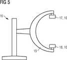
Die Erfindung beansprucht auch ein Bildgebungsgerät mit einem Röntgendetektor und einem Röntgenstrahler, jeweils angeordnet in einer erfindungsgemäßen Anordnung.The invention also claims an imaging device with an X-ray detector and an X-ray emitter, each arranged in an arrangement according to the invention.
Weitere Besonderheiten und Vorteile der Erfindung werden aus den nachfolgenden Erläuterungen mehrerer Ausführungsbeispiele anhand von schematischen Zeichnungen ersichtlich.Other features and advantages of the invention will become apparent from the following explanations of several embodiments with reference to schematic drawings.
Es zeigen:Show it:
Detaillierte Beschreibung mehrerer AusführungsbeispieleDetailed description of several embodiments
Zwischen dem ersten und dem zweiten Rand
Bei einer Kollision, beispielsweise der zweiten Gehäuseschale
Das taktile Sensorelement
BezugszeichenlisteLIST OF REFERENCE NUMBERS
- 11
- Schlauchförmiges SensorelementTubular sensor element
- 22
- erste Gehäuseschalefirst housing shell
- 33
- zweite Gehäuseschalesecond housing shell
- 44
- erster Randfirst edge
- 55
- zweiter Randsecond edge
- 66
- Abstandselement/AbstandsgewirkSpacer / spacer fabric
- 77
- Gummilipperubber lip
- 88th
- Steuer- und AuswerteeinheitControl and evaluation unit
- 99
- Innenraum des Gehäuses
10 Interior of thehousing 10 - 1010
- Gehäusecasing
- 1111
- Objektobject
- 1212
- Druckleitungpressure line
- 1313
- Druckwandlerpressure transducer
- 1414
- Referenzdruckreference pressure
- 1515
- Luft-Druck-SchlauchAir-pressure hose
- 1616
- Bildgebungsgerätimaging device
- 1717
- RöntgenstrahlerX-ray
- 1818
- RöntgendetektorX-ray detector
- 1919
- C-BogenC-arm
- FF
- Kollisionskraftcollision force
ZITATE ENTHALTEN IN DER BESCHREIBUNG QUOTES INCLUDE IN THE DESCRIPTION
Diese Liste der vom Anmelder aufgeführten Dokumente wurde automatisiert erzeugt und ist ausschließlich zur besseren Information des Lesers aufgenommen. Die Liste ist nicht Bestandteil der deutschen Patent- bzw. Gebrauchsmusteranmeldung. Das DPMA übernimmt keinerlei Haftung für etwaige Fehler oder Auslassungen.This list of the documents listed by the applicant has been generated automatically and is included solely for the better information of the reader. The list is not part of the German patent or utility model application. The DPMA assumes no liability for any errors or omissions.
Zitierte PatentliteraturCited patent literature
- US 5570770[0002, 0005]US 5570770[0002, 0005]
- DE 102012219024 A1[0007]DE 102012219024 A1[0007]
Claims (11)
Translated fromGermanPriority Applications (2)
| Application Number | Priority Date | Filing Date | Title |
|---|---|---|---|
| DE102013225575.6ADE102013225575B4 (en) | 2013-12-11 | 2013-12-11 | Arrangement and method for collision detection and imaging device with an arrangement for collision detection |
| CN201420748355.4UCN204612843U (en) | 2013-12-11 | 2014-12-03 | For identifying the device of collision and there is the imaging device of the device identifying collision |
Applications Claiming Priority (1)
| Application Number | Priority Date | Filing Date | Title |
|---|---|---|---|
| DE102013225575.6ADE102013225575B4 (en) | 2013-12-11 | 2013-12-11 | Arrangement and method for collision detection and imaging device with an arrangement for collision detection |
Publications (2)
| Publication Number | Publication Date |
|---|---|
| DE102013225575A1true DE102013225575A1 (en) | 2015-06-11 |
| DE102013225575B4 DE102013225575B4 (en) | 2018-04-19 |
Family
ID=53185282
Family Applications (1)
| Application Number | Title | Priority Date | Filing Date |
|---|---|---|---|
| DE102013225575.6AActiveDE102013225575B4 (en) | 2013-12-11 | 2013-12-11 | Arrangement and method for collision detection and imaging device with an arrangement for collision detection |
Country Status (2)
| Country | Link |
|---|---|
| CN (1) | CN204612843U (en) |
| DE (1) | DE102013225575B4 (en) |
Cited By (2)
| Publication number | Priority date | Publication date | Assignee | Title |
|---|---|---|---|---|
| CN114407017A (en)* | 2022-01-28 | 2022-04-29 | 广东弘讯智能科技有限公司 | Collision sensor, industrial robot and automatic adjustment method |
| EP4389012A1 (en)* | 2022-12-21 | 2024-06-26 | Siemens Healthineers AG | Tactile sensor cover and manufacturing method and medical device |
Families Citing this family (2)
| Publication number | Priority date | Publication date | Assignee | Title |
|---|---|---|---|---|
| CN107065775B (en)* | 2017-04-18 | 2019-08-02 | 上海柏楚电子科技股份有限公司 | The method of active dodge cutting head side crash in a kind of processing of numerically-controlled machine tool |
| CN115624344B (en)* | 2022-10-26 | 2025-07-22 | 上海联影医疗科技股份有限公司 | Anti-collision shell module and C-arm device |
Citations (7)
| Publication number | Priority date | Publication date | Assignee | Title |
|---|---|---|---|---|
| US5570770A (en) | 1992-09-14 | 1996-11-05 | U.S. Philips Corporation | Apparatus, in particular an x-ray examination apparatus, with arrangement for collision protection |
| JPH09328782A (en)* | 1996-06-12 | 1997-12-22 | Shin Caterpillar Mitsubishi Ltd | Work device controller of construction machine |
| DE10137250A1 (en)* | 2001-07-31 | 2003-02-13 | Bayerische Motoren Werke Ag | Sensor device for vehicles |
| US20070090931A1 (en)* | 2005-09-28 | 2007-04-26 | Hawes Kevin J | Pedestrian impact sensing apparatus for a vehicle bumper |
| DE102006050098A1 (en)* | 2005-10-28 | 2007-05-03 | Denso Corp., Kariya | Collision-detecting device for a vehicle comprises a unit for determining the flow value of a fluid flowing through an opening and collision-detecting unit for establishing whether a collision taken place based on the determined flow value |
| DE102011011962A1 (en)* | 2011-02-22 | 2012-08-23 | Continental Automotive Gmbh | Crash sensor for motor car, has deformable hose with cavity and pressure sensor for acquisition of pressure change in cavity of hose, where crash is resilient, and hose is made of cross linked silicone material |
| DE102012219024A1 (en) | 2012-10-18 | 2014-04-24 | Siemens Aktiengesellschaft | Housing panel module, arrangement and method with collision detection for medical devices |
- 2013
- 2013-12-11DEDE102013225575.6Apatent/DE102013225575B4/enactiveActive
- 2014
- 2014-12-03CNCN201420748355.4Upatent/CN204612843U/ennot_activeExpired - Lifetime
Patent Citations (7)
| Publication number | Priority date | Publication date | Assignee | Title |
|---|---|---|---|---|
| US5570770A (en) | 1992-09-14 | 1996-11-05 | U.S. Philips Corporation | Apparatus, in particular an x-ray examination apparatus, with arrangement for collision protection |
| JPH09328782A (en)* | 1996-06-12 | 1997-12-22 | Shin Caterpillar Mitsubishi Ltd | Work device controller of construction machine |
| DE10137250A1 (en)* | 2001-07-31 | 2003-02-13 | Bayerische Motoren Werke Ag | Sensor device for vehicles |
| US20070090931A1 (en)* | 2005-09-28 | 2007-04-26 | Hawes Kevin J | Pedestrian impact sensing apparatus for a vehicle bumper |
| DE102006050098A1 (en)* | 2005-10-28 | 2007-05-03 | Denso Corp., Kariya | Collision-detecting device for a vehicle comprises a unit for determining the flow value of a fluid flowing through an opening and collision-detecting unit for establishing whether a collision taken place based on the determined flow value |
| DE102011011962A1 (en)* | 2011-02-22 | 2012-08-23 | Continental Automotive Gmbh | Crash sensor for motor car, has deformable hose with cavity and pressure sensor for acquisition of pressure change in cavity of hose, where crash is resilient, and hose is made of cross linked silicone material |
| DE102012219024A1 (en) | 2012-10-18 | 2014-04-24 | Siemens Aktiengesellschaft | Housing panel module, arrangement and method with collision detection for medical devices |
Cited By (3)
| Publication number | Priority date | Publication date | Assignee | Title |
|---|---|---|---|---|
| CN114407017A (en)* | 2022-01-28 | 2022-04-29 | 广东弘讯智能科技有限公司 | Collision sensor, industrial robot and automatic adjustment method |
| CN114407017B (en)* | 2022-01-28 | 2024-04-26 | 广东弘讯智能科技有限公司 | Industrial robot and automatic adjustment method |
| EP4389012A1 (en)* | 2022-12-21 | 2024-06-26 | Siemens Healthineers AG | Tactile sensor cover and manufacturing method and medical device |
Also Published As
| Publication number | Publication date |
|---|---|
| CN204612843U (en) | 2015-09-02 |
| DE102013225575B4 (en) | 2018-04-19 |
Similar Documents
| Publication | Publication Date | Title |
|---|---|---|
| DE102013225575B4 (en) | Arrangement and method for collision detection and imaging device with an arrangement for collision detection | |
| DE102015206230B4 (en) | CT system and method for determining the position and range of a mobile operating element for controlling the CT system | |
| WO2011018439A1 (en) | Operating unit, device, and method | |
| DE19826484A1 (en) | Sensor for location and / or time-resolving force or pressure measurement | |
| EP2861938A1 (en) | Capacitive sensor for detecting the movement of an object | |
| EP1770480A2 (en) | Method and evaluation of touch signals and touch unit | |
| DE102014224171B4 (en) | Arrangement with a collision detection device, medical imaging device with a collision detection device and method for operating a collision detection device | |
| DE102013217533B4 (en) | Positioning device and a patient positioning device and a medical imaging device with the positioning device | |
| EP2853195B1 (en) | Seat or couch in a vehicle with a sensor for non-contact electrocardiographic measurement | |
| EP3309967A1 (en) | Capacitive switching device | |
| DE602005004785T2 (en) | COLLISION DETECTION APPARATUS AND METHOD | |
| EP4128536A1 (en) | Sensor device for an operator control input device | |
| DE102012219024B4 (en) | Housing panel module, arrangement and method with collision detection for medical devices | |
| EP3497407B1 (en) | Monitoring relative motion of two elements | |
| DE19958305A1 (en) | Device for functional monitoring of finger protection strip for vehicle doors, has airtight hollow chamber in which pipeline connected with compressed air source opens out and pressure pulse brings about alarm signal | |
| DE102009017842B4 (en) | Method and device for emergency shutdown of an electrically controlled system and medical device with such a device | |
| EP1835303B2 (en) | Method for operating a surroundings recognition system of a vehicle, in particular the recognition system for the immediate vicinity or parking assistance and corresponding system | |
| DE102016204676A1 (en) | X-ray image detector and X-ray imaging device with a collision detection unit and method for detecting a collision | |
| DE102011084295A1 (en) | Movable c-arm X-ray unit for recording X-ray images of patient in clinic, has measuring instruments in active connection with c-arm, X-ray source and X-ray detector such that accelerations of arm, source and detector are measurable | |
| EP3436835B1 (en) | Protective clothing | |
| DE102013202703A1 (en) | Apparatus and method for collision detection in a medical device | |
| DE2522556C2 (en) | Device for controlling the heating of a rotating body, in particular a vehicle wheel | |
| EP3224955B1 (en) | Switch actuating device, mobile device, and method for actuating a switch by means of a non-tactile gesture | |
| DE102011001976B4 (en) | Measuring head for a coordinate measuring machine | |
| DE102009006764A1 (en) | X-ray system for taking photographs of patient from different angles, has system control receiving trigger signal and blocking movement of photograph system depending on received trigger signal |
Legal Events
| Date | Code | Title | Description |
|---|---|---|---|
| R012 | Request for examination validly filed | ||
| R079 | Amendment of ipc main class | Free format text:PREVIOUS MAIN CLASS: G01L0001220000 Ipc:G01L0001020000 | |
| R016 | Response to examination communication | ||
| R081 | Change of applicant/patentee | Owner name:SIEMENS HEALTHCARE GMBH, DE Free format text:FORMER OWNER: SIEMENS AKTIENGESELLSCHAFT, 80333 MUENCHEN, DE | |
| R018 | Grant decision by examination section/examining division | ||
| R020 | Patent grant now final | ||
| R081 | Change of applicant/patentee | Owner name:SIEMENS HEALTHINEERS AG, DE Free format text:FORMER OWNER: SIEMENS HEALTHCARE GMBH, MUENCHEN, DE |