DE102013224753A1 - Instrument, in particular a medical-endoscopic instrument or technoscope - Google Patents
Instrument, in particular a medical-endoscopic instrument or technoscopeDownload PDFInfo
- Publication number
- DE102013224753A1 DE102013224753A1DE102013224753.2ADE102013224753ADE102013224753A1DE 102013224753 A1DE102013224753 A1DE 102013224753A1DE 102013224753 ADE102013224753 ADE 102013224753ADE 102013224753 A1DE102013224753 A1DE 102013224753A1
- Authority
- DE
- Germany
- Prior art keywords
- instrument
- shaft
- joint part
- instrument according
- tool carrier
- Prior art date
- Legal status (The legal status is an assumption and is not a legal conclusion. Google has not performed a legal analysis and makes no representation as to the accuracy of the status listed.)
- Withdrawn
Links
- 230000033001locomotionEffects0.000claimsabstractdescription20
- 238000005096rolling processMethods0.000claimsdescription24
- 238000005452bendingMethods0.000claimsdescription15
- 230000003042antagnostic effectEffects0.000claimsdescription4
- 230000005540biological transmissionEffects0.000description2
- 230000000694effectsEffects0.000description2
- BUHVIAUBTBOHAG-FOYDDCNASA-N(2r,3r,4s,5r)-2-[6-[[2-(3,5-dimethoxyphenyl)-2-(2-methylphenyl)ethyl]amino]purin-9-yl]-5-(hydroxymethyl)oxolane-3,4-diolChemical compoundCOC1=CC(OC)=CC(C(CNC=2C=3N=CN(C=3N=CN=2)[C@H]2[C@@H]([C@H](O)[C@@H](CO)O2)O)C=2C(=CC=CC=2)C)=C1BUHVIAUBTBOHAG-FOYDDCNASA-N0.000description1
- 230000008878couplingEffects0.000description1
- 238000010168coupling processMethods0.000description1
- 238000005859coupling reactionMethods0.000description1
- 238000005520cutting processMethods0.000description1
- 230000001419dependent effectEffects0.000description1
- 238000011161developmentMethods0.000description1
- 230000018109developmental processEffects0.000description1
- 239000003814drugSubstances0.000description1
- 238000001839endoscopyMethods0.000description1
- 239000004519greaseSubstances0.000description1
- 238000005461lubricationMethods0.000description1
- 238000004519manufacturing processMethods0.000description1
- 230000002093peripheral effectEffects0.000description1
Images


Classifications
- A—HUMAN NECESSITIES
- A61—MEDICAL OR VETERINARY SCIENCE; HYGIENE
- A61B—DIAGNOSIS; SURGERY; IDENTIFICATION
- A61B34/00—Computer-aided surgery; Manipulators or robots specially adapted for use in surgery
- A61B34/70—Manipulators specially adapted for use in surgery
- A61B34/71—Manipulators operated by drive cable mechanisms
- A—HUMAN NECESSITIES
- A61—MEDICAL OR VETERINARY SCIENCE; HYGIENE
- A61B—DIAGNOSIS; SURGERY; IDENTIFICATION
- A61B34/00—Computer-aided surgery; Manipulators or robots specially adapted for use in surgery
- A61B34/30—Surgical robots
- A—HUMAN NECESSITIES
- A61—MEDICAL OR VETERINARY SCIENCE; HYGIENE
- A61B—DIAGNOSIS; SURGERY; IDENTIFICATION
- A61B17/00—Surgical instruments, devices or methods
- A61B17/28—Surgical forceps
- A61B17/29—Forceps for use in minimally invasive surgery
- A—HUMAN NECESSITIES
- A61—MEDICAL OR VETERINARY SCIENCE; HYGIENE
- A61B—DIAGNOSIS; SURGERY; IDENTIFICATION
- A61B17/00—Surgical instruments, devices or methods
- A61B17/00234—Surgical instruments, devices or methods for minimally invasive surgery
- A61B2017/00292—Surgical instruments, devices or methods for minimally invasive surgery mounted on or guided by flexible, e.g. catheter-like, means
- A61B2017/003—Steerable
- A61B2017/00318—Steering mechanisms
- A61B2017/00323—Cables or rods
- A—HUMAN NECESSITIES
- A61—MEDICAL OR VETERINARY SCIENCE; HYGIENE
- A61B—DIAGNOSIS; SURGERY; IDENTIFICATION
- A61B17/00—Surgical instruments, devices or methods
- A61B17/28—Surgical forceps
- A61B17/29—Forceps for use in minimally invasive surgery
- A61B2017/2926—Details of heads or jaws
- A61B2017/2927—Details of heads or jaws the angular position of the head being adjustable with respect to the shaft
- A—HUMAN NECESSITIES
- A61—MEDICAL OR VETERINARY SCIENCE; HYGIENE
- A61B—DIAGNOSIS; SURGERY; IDENTIFICATION
- A61B34/00—Computer-aided surgery; Manipulators or robots specially adapted for use in surgery
- A61B34/30—Surgical robots
- A61B2034/305—Details of wrist mechanisms at distal ends of robotic arms
Landscapes
- Health & Medical Sciences (AREA)
- Surgery (AREA)
- Engineering & Computer Science (AREA)
- Life Sciences & Earth Sciences (AREA)
- Medical Informatics (AREA)
- Robotics (AREA)
- Biomedical Technology (AREA)
- Heart & Thoracic Surgery (AREA)
- Nuclear Medicine, Radiotherapy & Molecular Imaging (AREA)
- Molecular Biology (AREA)
- Animal Behavior & Ethology (AREA)
- General Health & Medical Sciences (AREA)
- Public Health (AREA)
- Veterinary Medicine (AREA)
- Surgical Instruments (AREA)
- Endoscopes (AREA)
- Instruments For Viewing The Inside Of Hollow Bodies (AREA)
Abstract
Translated fromGermanDescription
Translated fromGermanDie Erfindung betrifft ein Instrument und insbesondere ein medizinisch-endoskopisches Instrument oder ein Technoskop.The invention relates to an instrument and in particular a medical-endoscopic instrument or a technoscope.
Im Bereich der Medizin und dort insbesondere im Bereich der Endoskopie werden Schaftinstrumente eingesetzt, die an dem distalen Ende eines Schaftes einen Instrumentenkopf mit einem daran angeordneten Werkzeug aufweisen. Instrumente dieser Art, bei denen es sich zum Beispiel um Fass- oder Schneidinstrumente handeln kann, finden darüber hinaus auch auf anderen Gebieten, beispielsweise bei Technoskopen zum Einsatz in Hohlräumen technischer Objekte Verwendung.In the field of medicine, and in particular in the field of endoscopy, shaft instruments are used which have at the distal end of a shaft an instrument head with a tool arranged thereon. Instruments of this type, which may be, for example, drum or cutting instruments, are also used in other fields, for example in technoscopes for use in cavities of technical objects use.
Den Ausgangspunkt der Erfindung bilden solche Instrumente, bei denen der Instrumentenkopf relativ zu dem Schaft und das Werkzeug oder zumindest ein Teil des Werkzeugs relativ zu einem Werkzeugträger des Instrumentenkopfes abwinkelbar sind. Ein derartiges Instrument ist aus
Hierbei erweist es sich als nachteilig, dass zur Steuerung der Abwinkelung des Instrumentenkopfes konstruktionsbedingt nur vergleichsweise kleine Momente auf das Gelenkteil übertragen werden können. Ein weiterer Nachteil dieses Instruments besteht darin, dass das Gelenkteil selbst bei einer Gesamtabwinkelung des Instrumentenkopfes von +/–120° nur eine seitliche Auslenkung von +/–60° erfährt, sodass die Abwinkelung des Instrumentenkopfes relativ zu dem Schaft nur verhältnismäßig grob einstellbar ist.In this case, it proves to be disadvantageous that due to the design, only comparatively small moments can be transmitted to the joint part in order to control the bending of the instrument head. Another disadvantage of this instrument is that the joint part undergoes only a lateral deflection of +/- 60 ° even with a total angulation of the instrument head of +/- 120 °, so that the bending of the instrument head relative to the shaft is only relatively coarse adjustable.
Vor diesem Hintergrund liegt der Erfindung die Aufgabe zugrunde, ein Instrument der in Rede stehenden Art zu schaffen, welches die oben beschriebenen Nachteile nicht aufweist.Against this background, the invention has for its object to provide an instrument of the type in question, which does not have the disadvantages described above.
Diese Aufgabe wird durch ein Instrument mit den in Anspruch 1 angegebenen Merkmalen gelöst. Vorteilhafte Weiterbildungen dieses Instruments ergeben sich aus den Unteransprüchen, der nachfolgenden Beschreibung sowie der Zeichnung. Hierbei können die in den Unteransprüchen angegebenen Merkmale vorteilhaft in der angegebenen Kombination, aber auch, soweit technisch sinnvoll, für sich oder in anderer Kombination zur Ausgestaltung der Erfindung beitragen.This object is achieved by an instrument having the features specified in claim 1. Advantageous developments of this instrument will become apparent from the dependent claims, the following description and the drawings. In this case, the features specified in the subclaims can advantageously contribute in the specified combination, but also, as far as is technically meaningful, alone or in another combination for the embodiment of the invention.
Das erfindungsgemäße Instrument ist bevorzugt ein medizinisch-endoskopisches Instrument. Es kann sich bei ihm aber auch um ein Technoskop handeln, das in schwer zugänglichen Hohlräumen technischer Objekte eingesetzt wird. Wie bei solchen Instrumenten üblich, weist auch das erfindungsgemäße Instrument einen länglichen, vorzugsweise gerade und starr ausgebildeten Schaft mit einem distalseitig daran angeordneten Instrumentenkopf auf.The instrument according to the invention is preferably a medical-endoscopic instrument. But it can also be a technoscope, which is used in hard to reach cavities of technical objects. As usual with such instruments, the instrument according to the invention also has an elongated, preferably straight and rigid shaft with an instrument head arranged distally thereon.
Der Instrumentenkopf weist mindestens ein an dem distalen Schaftende abwinkelbar angelenktes Gelenkteil und einen distalseitig an dem Gelenkteil in der Abwinkelungsebene des Gelenkteils abwinkelbar angelenkten Werkzeugträger auf. Erfindungsgemäß ist an dem proximalen Ende des Gelenkteils eine Verzahnung vorzugsweise in Form eines Zahnradsegments ausgebildet, die mit einem in dem Schaft drehbar gelagerten und mit einem Seilzugpaar zur Bewegungssteuerung des Instrumentenkopfes bewegungsgekoppelten Verzahnkörper in Eingriff ist. Die Abwinkelung des Instrumentenkopfes erfolgt hierbei durch eine Drehbewegung des Verzahnkörpers, die durch Zugbeanspruchung eines der Seilzüge des mit dem Verzahnkörper bewegungsgekoppelten antagonistisch auf den Verzahnkörper wirkenden Seilzugpaares verursacht wird. Aufgrund der Maßnahme, das Gelenkteil und damit den Werkzeugträger bzw. den gesamten Instrumentenkopf über den in dem Schaft proximalseitig der Anlenkung des Gelenkteils angeordneten Verzahnkörper zu verschwenken, ist es bei dem erfindunsgemäßen Instrument, anders als bei den bislang bekannten Instrumenten der in Rede stehenden Art, nicht erforderlich, die Seilzüge über den Abwinkelungsbereich zwischen Schaft und Instrumentenkopf hinweg zu führen. Stattdessen sind die Seilzüge unabhängig von der Abwinkelung des Instrumentenkopfes in dem Schaft immer weitestgehend linear geführt, sodass bei der Abwinkelung des Instrumentenkopfes einer der Seilzüge in gleichem Maße in distaler Richtung bewegt wird, wie der andere in proximaler Richtung bewegt wird.The instrument head has at least one articulated part, which is articulated at an angle to the distal end of the shaft, and a tool carrier, which can be angled distally on the articulated part in the articulation plane of the articulated part. According to the invention, a toothing is preferably formed in the form of a gear segment at the proximal end of the joint part, which is engaged with a toothed body rotatably mounted in the shaft and motion-coupled with a cable pair for controlling the movement of the instrument head. The bending of the instrument head takes place here by a rotational movement of the toothed body, which is caused by tensile stress of one of the cables of motion-coupled with the toothed body antagonistic acting on the toothed body cable pair. Due to the measure of pivoting the joint part and thus the tool carrier or the entire instrument head over the toothed body arranged in the shank on the proximal side of the articulation part, it is in the inventive instrument, unlike the previously known instruments of the type in question, It is not necessary to guide the cables over the bending area between the shaft and the instrument head. Instead, regardless of the angulation of the instrument head in the shaft, the cables are always guided largely linearly, so that, when the instrument head is bent, one of the cables moves to the same extent in the distal direction as the other is moved in the proximal direction.
Zur Bewegungskopplung des Seilzugpaares mit dem Verzahnkörper ist bevorzugt mindestens eine Betätigungsrolle vorgesehen, die achsgleich mit dem Verzahnkörper in dem Schaft drehbar gelagert ist und mit dem Verzahnkörper drehfest verbunden ist. Mit dieser Betätigungsrolle ist das Seilzugpaar zweckmäßigerweise derart verbunden, dass die Betätigungsrolle und der Verzahnkörper bei einer Zugbeanspruchung eines ersten Seilzugs des Seilzugpaares in eine erste Richtung gedreht werden und bei einer Zugbeanspruchung des anderen Seilzugs des Seilzugpaares in eine zweite, entgegengesetzte Richtung gedreht werden. Die Befestigung der Seilzüge des Seilzugpaares an der Befestigungsrolle erfolgt günstig umfänglich der Befestigungsrolle, wobei die Seilzüge an der Betätigungsrolle typischerweise bezogen auf die Drehachse der Betätigungsrolle an zwei einander gegenüberliegenden Seiten befestigt sind. Als Betätigungsrolle ist zwar bevorzugt ein Bauteil mit einer kreisförmigen Querschnittskontur vorgesehen, allerdings sind im Sinne der Erfindung unter dem Begriff „Betätigungsrolle“ grundsätzlich alle Bauteile zu verstehen, die lediglich einen teilkreisförmigen oder teilkreisähnlichen Umfangsabschnitt aufweisen, der von den beiden Seilzügen teilweise umschlungen wird, ansonsten aber eine beliebige Umfangskontur aufweisen können.For coupling movement of the cable pair with the toothed body at least one actuating roller is preferably provided, which is rotatably mounted coaxially with the toothed body in the shaft and is rotatably connected to the toothed body. With this actuating roller, the cable pair is expediently connected such that the actuating roller and the toothed body are rotated in a first direction at a tensile stress of a first cable of the cable pair and at a tensile stress of the other cable of the cable pair are rotated in a second, opposite direction. The attachment of the cables of the cable pair to the mounting roller is conveniently circumferentially the mounting roller, the cables are attached to the actuating roller typically based on the axis of rotation of the actuating roller on two opposite sides. Although a component with a circular cross-sectional contour is preferably provided as the actuating roller, in the sense of the invention the term "actuating roller" basically means all components which have only a part-circular or part-circle-shaped peripheral portion which is partially wrapped around the two cable pulls, otherwise but may have any circumferential contour.
Sinnvollerweise ist vorzusehen, dass die Betätigungsrolle einen möglichst großen Wirkradius aufweist, um bei möglichst geringem Kraftaufwand das zum Abwinkeln des Instrumentenkopfes erforderliche Bewegungsmoment erzeugen zu können. Zu diesem Zweck weist die in dem Schaft angeordnete Betätigungsrolle vorteilhaft einen Durchmesser auf, der im Wesentlichen mit dem Innendurchmesser des Schaftes übereinstimmt. Diese Dimensionierung der Betätigungsrolle setzt typischerweise voraus, dass die Betätigungsrolle zumindest in unmittelbarer Nähe der Mittelachse des Schaftes drehbar gelagert ist.It is expedient to provide that the actuating roller has the largest possible effective radius in order to be able to generate the movement moment required for bending the instrument head with the least possible expenditure of force. For this purpose, the actuating roller arranged in the shaft advantageously has a diameter which substantially coincides with the inner diameter of the shaft. This dimensioning of the actuating roller typically requires that the actuating roller is rotatably mounted at least in the immediate vicinity of the central axis of the shaft.
Der Verzahnkörper ist vorzugsweise quer zu seiner Drehachse zweigeteilt ausgebildet, wobei die beiden Teile des Verzahnkörpers relativ zueinander drehbar sind. In Verbindung mit dieser Ausgestaltung ist weiter vorteilhaft vorgesehen, dass jeder der beiden Teile des Verzahnkörpers drehfest mit einer Betätigungsrolle verbunden ist, an welcher jeweils ein Seilzug bezogen auf den anderen Seilzug antagonistisch angreift. Diese konstruktiven Maßnahmen dienen dazu, ein bei einem einteiligen Verzahnkörper bei Umkehr der Drehrichtung des Verzahnkörpers ggf. auftretendes Zahnspiel zu verhindern, da aufgrund der Vorspannung der mit den beiden Betätigungsrollen verbundenen Seilzüge zumindest immer eines der Teile des Verzahnkörpers mit der an dem proximalen Ende des Gelenkteils ausgebildeten Verzahnung spielfrei in Eingriff ist.The toothed body is preferably formed in two parts transversely to its axis of rotation, wherein the two parts of the toothed body are rotatable relative to each other. In connection with this embodiment, it is further advantageously provided that each of the two parts of the toothed body is rotatably connected to an actuating roller on which a respective cable draws antagonistic with respect to the other cable pull. These constructive measures serve to prevent a backlash occurring in a one-piece gear when reversing the direction of rotation of the gear body, since due to the bias of the cables connected to the two actuators at least one of the parts of the gear body with the at the proximal end of the joint part trained gearing play is engaged.
Um eine kontrollierte Abwinkelung des Werkzeugträgers relativ zu dem Gelenkteil zu gewährleisten, ist der Werkzeugträger bevorzugt mit dem Schaft über mindestens eine Wälzkörperpaarung gekoppelt. So ist vorzugsweise vorgesehen, dass an dem distalen Ende des Schaftes mindestens ein starr mit dem Schaft verbundener Wälzkörper angeordnet ist, der in reibschlüssiger oder vorzugsweise in formschlüssiger Verbindung mit einem an dem Werkzeugträger starr angeordneten Wälzkörper steht. Bei einer über den Verzahnkörper eingeleiteten Abwinkelung des Gelenkteils führt dies zu einer definierten Abrollbewegung des werkzeugträgerseitigen Wälzkörpers auf dem schaftseitigen Wälzkörper und damit einhergehend zu einer definierten Abwinkelung des Instrumentenkopfes relativ zu dem Schaft.In order to ensure a controlled bending of the tool carrier relative to the joint part, the tool carrier is preferably coupled to the shaft via at least one Wälzkörperpaarung. Thus, it is preferably provided that at least one rigidly connected to the shaft rolling elements is arranged at the distal end of the shaft, which is in frictional or preferably in positive connection with a rigidly arranged on the tool carrier rolling elements. In an introduced over the gear body bending of the joint part, this leads to a defined rolling movement of the tool carrier side rolling elements on the shaft side rolling elements and, consequently, to a defined bending of the instrument head relative to the shaft.
Die Wälzkörper der Wälzkörperpaarung sind bevorzugt verzahnt ausgebildet. Vorteilhafterweise ist somit zumindest ein mit dem Schaft starr verbundenes Zahnradsegment vorgesehen, das mit einem mit dem Werkzeugträger starr verbundenen Zahnradsegment in Eingriff ist. Sowohl die Art der an den Zahnradsegmenten ausgebildeten Verzahnung als auch die Art der an dem Gelenkteil und dem Verzahnkörper ausgebildeten Verzahnungen ist grundsätzlich beliebig. Beispielsweise können die Verzahnungen als Evolventenverzahnung ausgebildet sein. Eine solche Verzahnung hat den Vorteil, dass sie vergleichsweise unempfindlich auf Abstandsänderungen der beiden Zahnradsegmente voneinander reagiert und ihre Herstellung vergleichsweise wenig aufwändig ist. Allerdings erfolgt die Abwälzbewegung der Zahnradsegmente bei einer Evolventenverzahnung nicht völlig gleitfrei, sodass es zu unerwünschten Stick-Slip-Effekten kommen kann. Zwar ist es generell möglich, diesen Stick-Slip-Effekten mit einer Fett- oder Ölschmierung der Verzahnung entgegenzuwirken, allerdings ist eine solche Maßnahme bei einem medizinischen Instrument nur bedingt oder gar nicht möglich. Daher ist es insbesondere dann, wenn es sich bei dem erfindungsgemäßen Instrument um ein medizinisch-endoskopisches Instrument handelt, zweckmäßiger, eine auf reine Rollreibung optimierte Verzahnung, beispielsweise eine Zykloidenverzahnung zu verwenden.The rolling elements of the rolling element pairing are preferably formed toothed. Advantageously, at least one gear segment rigidly connected to the shaft is thus provided, which engages with a gear segment rigidly connected to the tool carrier. Both the type of toothing formed on the gear segments and the type of toothing formed on the joint part and the toothed body are basically arbitrary. For example, the teeth may be formed as involute. Such a toothing has the advantage that it reacts relatively insensitive to changes in the distance of the two gear segments from each other and their production is relatively inexpensive. However, the rolling movement of the gear segments in an involute gear is not completely slippery, so it can lead to unwanted stick-slip effects. Although it is generally possible to counteract these stick-slip effects with a grease or oil lubrication of the teeth, but such a measure in a medical instrument only partially or not possible. Therefore, if the instrument according to the invention is a medical-endoscopic instrument, it is more expedient to use toothing optimized for pure rolling friction, for example a cycloidal toothing.
Das Übersetzungsverhältnis zwischen dem Verzahnkörper und dem verzahnten Bereich des Gelenkteils und das Übersetzungsverhältnis der Wälzkörperpaarung zwischen Werkzeugträger und Schaft sind zweckmäßigerweise so gewählt, dass ein möglichst großes Moment zum Abwinkeln des Instrumentenkopfes zur Verfügung steht.The transmission ratio between the toothed body and the toothed region of the joint part and the transmission ratio of Wälzkörperpaarung between the tool carrier and shaft are suitably chosen so that the largest possible moment for bending the instrument head is available.
Bevorzugt bilden der Verzahnkörper und die damit in Eingriff befindliche Verzahnung des Gelenkteils ein Untersetzungsgetriebe, das heißt, vorzugsweise weist der Verzahnkörper einen geringeren Wälzdurchmesser, als der an dem Gelenkteil ausgebildete verzahnte Bereich auf, sodass bei Drehung des Verzahnkörpers der Winkel, um den das Gelenkteil dann verschwenkt wird, kleiner als der Drehwinkel des Verzahnkörpers ist. Dies ist insofern vorteilhaft, als sich auf diese Weise der Winkel, in dem der Instrumentenkopf relativ zu dem Schaft abgewinkelt werden soll, besonders genau einstellen lässt.The toothed body and the toothing of the joint part engaged therewith preferably form a reduction gear, that is, the toothed body preferably has a smaller rolling diameter than the toothed region formed on the joint part, so that when the toothed body rotates, the angle about which the joint part then rotates is pivoted, is smaller than the angle of rotation of the gear body. This is advantageous in that in this way the angle at which the instrument head is to be angled relative to the shaft can be adjusted particularly precisely.
Alternativ oder zusätzlich zu einem von dem Verzahnkörper und der Verzahnung des Gelenkteils gebildeten Untersetzungsgetriebe können auch ein schaftseitig angeordneter Wälzkörper und ein werkzeugträgerseitig angeordneter Wälzkörper der Wälzkörperpaarung zwischen dem Werkzeugträger und dem Schaft ein Untersetzungsgetriebe bilden. Hierbei ist vorgesehen, dass der schaftseitige Wälzkörper einen geringeren Wälzdurchmesser als der werkzeugträgerseitige Wälzkörper aufweist. Auch mit dieser Maßnahme wird bewirkt, dass der Winkel, in dem der Instrumentenkopf relativ zu dem Schaft abgewinkelt werden soll, besonders genau eingestellt werden kann.Alternatively or in addition to a reduction gear formed by the gear body and the toothing of the joint part can also be a shaft side arranged rolling elements and a Tool carrier side arranged rolling elements of the rolling element pairing between the tool carrier and the shaft form a reduction gear. It is provided that the shaft-side rolling elements has a smaller rolling diameter than the tool carrier-side rolling elements. This measure also causes the angle at which the instrument head is to be angled relative to the shaft to be adjusted particularly accurately.
Bevorzugt werden das von dem Verzahnkörper und der Verzahnung des Gelenkteils gebildete Untersetzungsgetriebe und das von den beiden Wälzkörpern der Wälzkörperpaarung zwischen Werkzeugträger und Schaft gebildete Untersetzungsgetriebe so ausgelegt, dass sich bei der Abwinkelung des Instrumentenkopfes das Moment um den Momentanpol der Bewegung gegenüber dem auf die Betätigungsrolle ausgeübten Moment vergrößert. Weiter bevorzugt werden das von dem Verzahnkörper und der Verzahnung des Gelenkteils gebildete Untersetzungsgetriebe und das von den beiden Wälzkörpern der Wälzkörperpaarung zwischen Werkzeugträger und Schaft gebildete Untersetzungsgetriebe so ausgelegt, dass die Betätigungsrolle und damit einhergehend der Verzahnkörper um nahezu +/–180° verdreht werden müssen, um eine Abwinkelung des Werkzeugträgers relativ zu dem Schaft von +/–120° zu bewirken. Zu diesem Zweck ist vorteilhaft vorgesehen, dass die Seilzüge des Seilzugpaares die Betätigungsrolle in einer Grundstellung des Instruments, in welcher der Instrumentenkopf in gerader Verlängerung des Schaftes angeordnet ist, jeweils in einem Winkelbereich von zumindest 180° umschlingen. Ist eine andere Abwinkelung des Werkzeugträgers als die vorab beschriebene von +/–120° gefordert, so kann die Gesamtuntersetzung der beschriebenen Wälzkörperpaarungen konstruktiv so ausgeführt werden, dass die maximal mögliche Seilbewegung die geforderte Abwinkelung des Werkzeugträgers ergibt.Preferably, the reduction gear formed by the toothing body and the toothing of the joint part and the reduction gear formed by the two rolling elements of Wälzkörperpaarung between the tool carrier and shaft are designed so that at the bend of the instrument head, the moment about the instantaneous pole of movement relative to that exerted on the actuating roller Moment increased. More preferably, the reduction gear formed by the toothed body and the toothing of the joint part and the reduction gear formed by the two rolling elements of Wälzkörperpaarung between the tool carrier and shaft are designed so that the actuating roller and, consequently, the toothed body must be rotated by nearly +/- 180 °, to cause a bending of the tool carrier relative to the shaft of +/- 120 °. For this purpose, it is advantageously provided that the cables of the pair of cables loop around the actuating roller in a basic position of the instrument, in which the instrument head is arranged in a straight extension of the shaft, in each case in an angular range of at least 180 °. If a different bend of the tool carrier is required than the one described above of +/- 120 °, then the overall reduction of the rolling element pairings described can be designed so that the maximum possible cable movement results in the required bending of the tool carrier.
Nachfolgend ist die Erfindung anhand von in der Zeichnung dargestellten Ausführungsbeispielen näher erläutert. In der Zeichnung zeigt schematisch vereinfacht und in unterschiedlichen Maßstäben:The invention is explained in more detail with reference to embodiments shown in the drawing. In the drawing shows schematically simplified and in different scales:
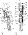
Bei dem in der Zeichnung dargestellten Instrument handelt es sich um ein medizinisch-endoskopisches Instrument in Form einer Zange. Dieses Instrument weist einen länglichen, hohlzylindrisch ausgebildeten Schaft
Das distale Ende des Schaftes
Distalseitig schließt sich an das Gelenkteil
Aufgrund der schwenkbeweglichen Anordnung des Gelenkteils
Um eine definierte Abwinkelung des Werkzeugträgers
An dem abgerundeten proximalen Ende des Gelenkteils
Auf dem Gelenkstift
Der Werkzeugträger
Zur Steuerung der Maulteile
Außenseitig der an dem Endstück
Anhand der
In
BezugszeichenlisteLIST OF REFERENCE NUMBERS
- 22
- Schaft shaft
- 44
- Endstück tail
- 66
- Instrumentenkopf instrument head
- 88th
- Vorsprung head Start
- 1010
- Gelenkstift pintle
- 1212
- Gelenkteil joint part
- 1414
- Werkzeugträger tool carrier
- 1616
- Vorsprung head Start
- 1818
- Gelenkstift pintle
- 2020
- Gelenkstift pintle
- 2222
- Verzahnkörper Verzahnkörper
- 2424
- Betätigungsrolle actuating roll
- 2626
- Seilzug cable
- 2828
- Seilzug cable
- 3030
- Einschnitt incision
- 3232
- Maulteil jaw
- 3434
- Maulteil jaw
- 3636
- Wandungsabschnitt wall section
- 3838
- Wandungsabschnitt wall section
- 4040
- Loch hole
- 4242
- Seilzug cable
- 4444
- Seilzug cable
- 4646
- Seilzug cable
- 4848
- Seilzug cable
- 5050
- Betätigungsrolle actuating roll
- 5252
- Betätigungsrolle actuating roll
- 5454
- Führungsrolle leadership
- 5656
- Führungsrolle leadership
- 5858
- Führungsrolle leadership
- 6060
- Führungsrolle leadership
- 6262
- Verzahnkörper Verzahnkörper
- 6464
- Teil part
- 6666
- Teil part
- 6868
- Betätigungsrolle actuating roll
- AA
- Mittelachse central axis
- BB
- Mittelachse central axis
- CC
- Mittelachse central axis
- DD
- Schwenkachse swivel axis
ZITATE ENTHALTEN IN DER BESCHREIBUNG QUOTES INCLUDE IN THE DESCRIPTION
Diese Liste der vom Anmelder aufgeführten Dokumente wurde automatisiert erzeugt und ist ausschließlich zur besseren Information des Lesers aufgenommen. Die Liste ist nicht Bestandteil der deutschen Patent- bzw. Gebrauchsmusteranmeldung. Das DPMA übernimmt keinerlei Haftung für etwaige Fehler oder Auslassungen.This list of the documents listed by the applicant has been generated automatically and is included solely for the better information of the reader. The list is not part of the German patent or utility model application. The DPMA assumes no liability for any errors or omissions.
Zitierte PatentliteraturCited patent literature
- US 2007/0208375 A1[0003]US 2007/0208375 A1[0003]
Claims (11)
Translated fromGermanPriority Applications (6)
| Application Number | Priority Date | Filing Date | Title |
|---|---|---|---|
| DE102013224753.2ADE102013224753A1 (en) | 2013-12-03 | 2013-12-03 | Instrument, in particular a medical-endoscopic instrument or technoscope |
| US15/101,225US10413375B2 (en) | 2013-12-03 | 2014-11-10 | Instrument, in particular a medical endoscopic instrument or technoscope |
| EP14833337.0AEP3076882B1 (en) | 2013-12-03 | 2014-11-10 | Instrument, in particular a medical endoscopic instrument or technoscope |
| JP2016536151AJP6475726B2 (en) | 2013-12-03 | 2014-11-10 | Instruments, especially medical endoscopic instruments or technoscopes |
| ES14833337TES2759076T3 (en) | 2013-12-03 | 2014-11-10 | Instrument, in particular a medical-endoscopic instrument or technoscope |
| PCT/DE2014/200624WO2015081946A1 (en) | 2013-12-03 | 2014-11-10 | Instrument, in particular a medical endoscopic instrument or technoscope |
Applications Claiming Priority (1)
| Application Number | Priority Date | Filing Date | Title |
|---|---|---|---|
| DE102013224753.2ADE102013224753A1 (en) | 2013-12-03 | 2013-12-03 | Instrument, in particular a medical-endoscopic instrument or technoscope |
Publications (1)
| Publication Number | Publication Date |
|---|---|
| DE102013224753A1true DE102013224753A1 (en) | 2015-06-03 |
Family
ID=52440497
Family Applications (1)
| Application Number | Title | Priority Date | Filing Date |
|---|---|---|---|
| DE102013224753.2AWithdrawnDE102013224753A1 (en) | 2013-12-03 | 2013-12-03 | Instrument, in particular a medical-endoscopic instrument or technoscope |
Country Status (6)
| Country | Link |
|---|---|
| US (1) | US10413375B2 (en) |
| EP (1) | EP3076882B1 (en) |
| JP (1) | JP6475726B2 (en) |
| DE (1) | DE102013224753A1 (en) |
| ES (1) | ES2759076T3 (en) |
| WO (1) | WO2015081946A1 (en) |
Cited By (2)
| Publication number | Priority date | Publication date | Assignee | Title |
|---|---|---|---|---|
| WO2017064306A1 (en)* | 2015-10-16 | 2017-04-20 | Medical Microinstruments S.R.L. | A surgical tool |
| DE102020207018A1 (en) | 2020-06-04 | 2021-12-09 | Richard Wolf Gmbh | Instrument, in particular a medical endoscopic instrument or technoscope |
Families Citing this family (31)
| Publication number | Priority date | Publication date | Assignee | Title |
|---|---|---|---|---|
| EP2627278B1 (en) | 2010-10-11 | 2015-03-25 | Ecole Polytechnique Fédérale de Lausanne (EPFL) | Mechanical manipulator for surgical instruments |
| WO2013014621A2 (en) | 2011-07-27 | 2013-01-31 | Ecole Polytechnique Federale De Lausanne (Epfl) | Mechanical teleoperated device for remote manipulation |
| US12402960B2 (en) | 2010-10-11 | 2025-09-02 | Ecole Polytechnique Federale De Lausanne (Epfl) | Mechanical manipulator for surgical instruments |
| CN106659540B (en) | 2014-02-03 | 2019-03-05 | 迪斯塔莫申股份公司 | Mechanical teleoperated devices including interchangeable distal instruments |
| EP3185808B1 (en) | 2014-08-27 | 2022-02-23 | DistalMotion SA | Surgical system for microsurgical techniques |
| WO2016097861A1 (en) | 2014-12-19 | 2016-06-23 | Distalmotion Sa | Sterile interface for articulated surgical instruments |
| EP3653145B1 (en) | 2014-12-19 | 2024-01-24 | DistalMotion SA | Reusable surgical instrument for minimally invasive procedures |
| WO2016097873A2 (en) | 2014-12-19 | 2016-06-23 | Distalmotion Sa | Articulated handle for mechanical telemanipulator |
| EP3232951B1 (en)* | 2014-12-19 | 2023-10-25 | DistalMotion SA | Surgical instrument with articulated end-effector |
| WO2016097871A1 (en) | 2014-12-19 | 2016-06-23 | Distalmotion Sa | Docking system for mechanical telemanipulator |
| US10568709B2 (en) | 2015-04-09 | 2020-02-25 | Distalmotion Sa | Mechanical teleoperated device for remote manipulation |
| EP3280337B1 (en) | 2015-04-09 | 2019-11-13 | DistalMotion SA | Articulated hand-held instrument |
| WO2017037532A1 (en) | 2015-08-28 | 2017-03-09 | Distalmotion Sa | Surgical instrument with increased actuation force |
| JP6557731B2 (en)* | 2015-11-04 | 2019-08-07 | オリンパス株式会社 | Joint mechanism |
| JP6177486B1 (en)* | 2016-01-22 | 2017-08-09 | オリンパス株式会社 | Medical instruments |
| IT201700041980A1 (en) | 2017-04-14 | 2018-10-14 | Medical Microinstruments Spa | ROBOTIC ASSEMBLY FOR MICROSURGERY |
| US11058503B2 (en) | 2017-05-11 | 2021-07-13 | Distalmotion Sa | Translational instrument interface for surgical robot and surgical robot systems comprising the same |
| US10258418B2 (en)* | 2017-06-29 | 2019-04-16 | Ethicon Llc | System for controlling articulation forces |
| US12376927B2 (en) | 2018-02-07 | 2025-08-05 | Distalmotion Sa | Surgical robot systems comprising robotic telemanipulators and integrated laparoscopy |
| AU2019218707B2 (en) | 2018-02-07 | 2024-10-24 | Distalmotion Sa | Surgical robot systems comprising robotic telemanipulators and integrated laparoscopy |
| CN108724243B (en)* | 2018-08-17 | 2024-07-02 | 深圳市丞辉威世智能科技有限公司 | Flexible bionic joint and robot |
| CN109222861B (en)* | 2018-09-20 | 2022-03-04 | 深圳市精锋医疗科技股份有限公司 | Endoscope, operation arm, slave operation device, and surgical robot |
| US11510687B2 (en) | 2018-11-16 | 2022-11-29 | Joint Preservation Innovations, LLC | Surgical rotary cutting tool including articulable head |
| US12089865B2 (en) | 2018-11-16 | 2024-09-17 | Joint Preservation Innovations, LLC | Surgical rotary cutting tool including articulable head |
| CN112617968B (en)* | 2020-12-31 | 2022-08-26 | 杭州康基医疗器械有限公司 | Surgical forceps head structure capable of rotating in multiple directions |
| WO2023037273A1 (en) | 2021-09-13 | 2023-03-16 | Distalmotion Sa | Instruments for surgical robotic system and interfaces for the same |
| KR20230068324A (en)* | 2021-11-09 | 2023-05-17 | 주식회사 로엔서지컬 | Surgical joint |
| KR20240152824A (en) | 2021-12-17 | 2024-10-22 | 조인트 프리저베이션 이노베이션스, 엘엘씨 | Articulated rotary cutting tool |
| CN115300049B (en)* | 2022-08-25 | 2025-04-18 | 艺柏湾医疗科技(上海)有限公司 | Multi-degree-of-freedom surgical clamp |
| WO2024079672A1 (en)* | 2022-10-12 | 2024-04-18 | Multi-Scale Medical Robotics Center Limited | End-efector for robotic arms |
| US11844585B1 (en) | 2023-02-10 | 2023-12-19 | Distalmotion Sa | Surgical robotics systems and devices having a sterile restart, and methods thereof |
Citations (2)
| Publication number | Priority date | Publication date | Assignee | Title |
|---|---|---|---|---|
| US20050011296A1 (en)* | 2001-09-05 | 2005-01-20 | Mitsuhiro Koseki | Rotation transmission device |
| US20070208375A1 (en) | 2006-02-23 | 2007-09-06 | Kouji Nishizawa | Surgical device |
Family Cites Families (13)
| Publication number | Priority date | Publication date | Assignee | Title |
|---|---|---|---|---|
| JPS6310088U (en)* | 1986-07-08 | 1988-01-22 | ||
| JPH0642609A (en)* | 1992-05-28 | 1994-02-18 | Takashi Takahashi | Control transmission mechanism |
| US5710870A (en) | 1995-09-07 | 1998-01-20 | California Institute Of Technology | Decoupled six degree-of-freedom robot manipulator |
| US8241322B2 (en) | 2005-07-27 | 2012-08-14 | Tyco Healthcare Group Lp | Surgical device |
| JP3912251B2 (en) | 2002-10-02 | 2007-05-09 | 株式会社日立製作所 | manipulator |
| WO2007108635A1 (en)* | 2006-03-23 | 2007-09-27 | Lg Electronics Inc. | Method of moving tracks, method and apparatus of recording and/or playback |
| JP4755047B2 (en)* | 2006-08-08 | 2011-08-24 | テルモ株式会社 | Working mechanism and manipulator |
| JP5041361B2 (en)* | 2007-06-18 | 2012-10-03 | 株式会社日立製作所 | Manipulator and manipulator device using the same |
| JP5042738B2 (en)* | 2007-07-30 | 2012-10-03 | テルモ株式会社 | Working mechanism and cleaning method of medical manipulator |
| AU2008302043B2 (en)* | 2007-09-21 | 2013-06-27 | Covidien Lp | Surgical device |
| CA2709634C (en) | 2007-12-21 | 2017-04-25 | Benny Hon Bun Yeung | Surgical manipulator |
| US8887595B2 (en) | 2009-12-22 | 2014-11-18 | Intuitive Surgical Operations, Inc. | Instrument wrist with cycloidal surfaces |
| WO2013140426A1 (en)* | 2012-02-21 | 2013-09-26 | Calabrian High Tech Srl | Twin forceps for single access laparoscopy |
- 2013
- 2013-12-03DEDE102013224753.2Apatent/DE102013224753A1/ennot_activeWithdrawn
- 2014
- 2014-11-10USUS15/101,225patent/US10413375B2/enactiveActive
- 2014-11-10WOPCT/DE2014/200624patent/WO2015081946A1/enactiveApplication Filing
- 2014-11-10JPJP2016536151Apatent/JP6475726B2/enactiveActive
- 2014-11-10EPEP14833337.0Apatent/EP3076882B1/enactiveActive
- 2014-11-10ESES14833337Tpatent/ES2759076T3/enactiveActive
Patent Citations (2)
| Publication number | Priority date | Publication date | Assignee | Title |
|---|---|---|---|---|
| US20050011296A1 (en)* | 2001-09-05 | 2005-01-20 | Mitsuhiro Koseki | Rotation transmission device |
| US20070208375A1 (en) | 2006-02-23 | 2007-09-06 | Kouji Nishizawa | Surgical device |
Cited By (12)
| Publication number | Priority date | Publication date | Assignee | Title |
|---|---|---|---|---|
| WO2017064306A1 (en)* | 2015-10-16 | 2017-04-20 | Medical Microinstruments S.R.L. | A surgical tool |
| EP3361982A1 (en)* | 2015-10-16 | 2018-08-22 | Medical Microinstruments S.r.L. | A surgical tool |
| JP2018532531A (en)* | 2015-10-16 | 2018-11-08 | メディカル・マイクロインストゥルメンツ・ソチエタ・ペル・アツィオーニMedical Microinstruments S.P.A. | Surgical instruments |
| US10582975B2 (en) | 2015-10-16 | 2020-03-10 | Medical Microinstruments S.p.A. | Surgical tool |
| AU2016337031B2 (en)* | 2015-10-16 | 2021-08-05 | Medical Microinstruments, Inc. | A surgical tool |
| US11096748B2 (en) | 2015-10-16 | 2021-08-24 | Medical Microinstruments S.p.A. | Surgical tool |
| US11103319B2 (en) | 2015-10-16 | 2021-08-31 | Medical Microinstruments S.p.A. | Surgical tool |
| JP2021166718A (en)* | 2015-10-16 | 2021-10-21 | メディカル・マイクロインストゥルメンツ・ソチエタ・ペル・アツィオーニMedical Microinstruments S.P.A. | Surgical instrument |
| JP2021166719A (en)* | 2015-10-16 | 2021-10-21 | メディカル・マイクロインストゥルメンツ・ソチエタ・ペル・アツィオーニMedical Microinstruments S.P.A. | Surgical instrument |
| JP7249051B2 (en) | 2015-10-16 | 2023-03-30 | メディカル・マイクロインストゥルメンツ・インコーポレイテッド | surgical instruments |
| JP7249052B2 (en) | 2015-10-16 | 2023-03-30 | メディカル・マイクロインストゥルメンツ・インコーポレイテッド | surgical instruments |
| DE102020207018A1 (en) | 2020-06-04 | 2021-12-09 | Richard Wolf Gmbh | Instrument, in particular a medical endoscopic instrument or technoscope |
Also Published As
| Publication number | Publication date |
|---|---|
| JP2017500933A (en) | 2017-01-12 |
| ES2759076T3 (en) | 2020-05-07 |
| EP3076882B1 (en) | 2019-08-28 |
| US10413375B2 (en) | 2019-09-17 |
| EP3076882A1 (en) | 2016-10-12 |
| US20160302876A1 (en) | 2016-10-20 |
| WO2015081946A1 (en) | 2015-06-11 |
| JP6475726B2 (en) | 2019-02-27 |
Similar Documents
| Publication | Publication Date | Title |
|---|---|---|
| EP3076882B1 (en) | Instrument, in particular a medical endoscopic instrument or technoscope | |
| EP1464290B1 (en) | Surgical instrument | |
| EP1484024B1 (en) | Surgical instrument with handgrip and zero setting arrangment | |
| DE102012212510B4 (en) | Endoscopic instrument | |
| EP2510887B1 (en) | Tool for a micro-surgical instrument | |
| EP3020346B1 (en) | Medical instrument | |
| DE102012222755A1 (en) | Instrument e.g. medical endoscopic instrument, has actuating shaft that is movement coupled in region of pivot axis of instrument head arranged in articulated coupling with pivotable first mouth portion of tool | |
| DE102009037898A1 (en) | gripper | |
| DE102012219881A1 (en) | Endoscopic instrument | |
| DE102014217796B4 (en) | Instrument, in particular medical-endoscopic instrument or technoscope | |
| WO2014124846A1 (en) | Instrument, in particular medical endoscopic instrument or technoscope | |
| DE102012212094B4 (en) | Endoscopic instrument | |
| EP3779239A1 (en) | High speed transmission | |
| EP1721577B1 (en) | Endoscopic instrument | |
| DE102021119386A1 (en) | Bendable shaft for a medical hand instrument | |
| DE102021119528A1 (en) | Bearing arrangement of a swash plate in a steering gear component and surgical instrument | |
| EP2489315A1 (en) | Medical instrument | |
| DE102011085512A1 (en) | Handle for a medical instrument | |
| EP4376728B1 (en) | Surgical instrument and steering gear for same | |
| DE102014219195B4 (en) | Instrument, in particular medical-endoscopic shaft instrument | |
| DE102011088003A1 (en) | Medical instrument | |
| DE102014206930B4 (en) | Instrument, in particular medical endoscopic instrument | |
| DE102013114557A1 (en) | Medical instrument with flexible toothed belt | |
| EP4376730B1 (en) | Surgical instrument and steering gear for same | |
| DE102015215469A1 (en) | Instrument, in particular medical endoscopic instrument |
Legal Events
| Date | Code | Title | Description |
|---|---|---|---|
| R163 | Identified publications notified | ||
| R005 | Application deemed withdrawn due to failure to request examination |