DE102013224683A1 - ENDOSCOPIC HEAD AND ENDOSCOPE - Google Patents
ENDOSCOPIC HEAD AND ENDOSCOPEDownload PDFInfo
- Publication number
- DE102013224683A1 DE102013224683A1DE102013224683.8ADE102013224683ADE102013224683A1DE 102013224683 A1DE102013224683 A1DE 102013224683A1DE 102013224683 ADE102013224683 ADE 102013224683ADE 102013224683 A1DE102013224683 A1DE 102013224683A1
- Authority
- DE
- Germany
- Prior art keywords
- mid
- endoscope head
- endoscope
- conductor track
- head body
- Prior art date
- Legal status (The legal status is an assumption and is not a legal conclusion. Google has not performed a legal analysis and makes no representation as to the accuracy of the status listed.)
- Withdrawn
Links
- 239000004020conductorSubstances0.000claimsabstractdescription58
- 238000000465mouldingMethods0.000claimsdescription37
- 150000001875compoundsChemical class0.000claimsdescription17
- 238000004382pottingMethods0.000claimsdescription16
- 238000011010flushing procedureMethods0.000claimsdescription10
- 230000003287optical effectEffects0.000claimsdescription7
- 230000005611electricityEffects0.000abstract2
- 238000007373indentationMethods0.000description8
- 238000004873anchoringMethods0.000description5
- 230000002262irrigationEffects0.000description5
- 238000003973irrigationMethods0.000description5
- 239000000463materialSubstances0.000description5
- 238000001746injection mouldingMethods0.000description4
- 238000000034methodMethods0.000description4
- 230000004308accommodationEffects0.000description3
- 238000004519manufacturing processMethods0.000description3
- 210000002445nippleAnatomy0.000description3
- -1polypropylenePolymers0.000description3
- 239000004952PolyamideSubstances0.000description2
- 239000004697PolyetherimideSubstances0.000description2
- 239000004734Polyphenylene sulfideSubstances0.000description2
- 239000004743PolypropyleneSubstances0.000description2
- 238000001839endoscopyMethods0.000description2
- 238000002347injectionMethods0.000description2
- 239000007924injectionSubstances0.000description2
- 230000002093peripheral effectEffects0.000description2
- 239000004033plasticSubstances0.000description2
- 229920003023plasticPolymers0.000description2
- 229920002492poly(sulfone)Polymers0.000description2
- 229920002647polyamidePolymers0.000description2
- 229920001707polybutylene terephthalatePolymers0.000description2
- 229920001601polyetherimidePolymers0.000description2
- 239000005020polyethylene terephthalateSubstances0.000description2
- 229920000139polyethylene terephthalatePolymers0.000description2
- 229920000069polyphenylene sulfidePolymers0.000description2
- 229920001155polypropylenePolymers0.000description2
- 238000002604ultrasonographyMethods0.000description2
- 229920012266Poly(ether sulfone) PESPolymers0.000description1
- 239000004695Polyether sulfoneSubstances0.000description1
- 235000014443Pyrus communisNutrition0.000description1
- 239000004676acrylonitrile butadiene styreneSubstances0.000description1
- 230000004323axial lengthEffects0.000description1
- 230000015572biosynthetic processEffects0.000description1
- 230000037237body shapeEffects0.000description1
- 238000005266castingMethods0.000description1
- 238000010276constructionMethods0.000description1
- 230000001419dependent effectEffects0.000description1
- 238000011161developmentMethods0.000description1
- 230000018109developmental processEffects0.000description1
- 238000005553drillingMethods0.000description1
- 230000003670easy-to-cleanEffects0.000description1
- 239000004417polycarbonateSubstances0.000description1
- 229920000515polycarbonatePolymers0.000description1
- 229920006393polyether sulfonePolymers0.000description1
- 238000010926purgeMethods0.000description1
- 230000005855radiationEffects0.000description1
- 230000002000scavenging effectEffects0.000description1
- 230000008054signal transmissionEffects0.000description1
- 239000000243solutionSubstances0.000description1
- 229920001169thermoplasticPolymers0.000description1
- 229920001187thermosetting polymerPolymers0.000description1
- 239000004416thermosoftening plasticSubstances0.000description1
Images


Classifications
- A—HUMAN NECESSITIES
- A61—MEDICAL OR VETERINARY SCIENCE; HYGIENE
- A61B—DIAGNOSIS; SURGERY; IDENTIFICATION
- A61B1/00—Instruments for performing medical examinations of the interior of cavities or tubes of the body by visual or photographical inspection, e.g. endoscopes; Illuminating arrangements therefor
- A61B1/00064—Constructional details of the endoscope body
- A61B1/00071—Insertion part of the endoscope body
- A61B1/0008—Insertion part of the endoscope body characterised by distal tip features
- A61B1/00097—Sensors
- A—HUMAN NECESSITIES
- A61—MEDICAL OR VETERINARY SCIENCE; HYGIENE
- A61B—DIAGNOSIS; SURGERY; IDENTIFICATION
- A61B1/00—Instruments for performing medical examinations of the interior of cavities or tubes of the body by visual or photographical inspection, e.g. endoscopes; Illuminating arrangements therefor
- A61B1/00002—Operational features of endoscopes
- A61B1/00011—Operational features of endoscopes characterised by signal transmission
- A—HUMAN NECESSITIES
- A61—MEDICAL OR VETERINARY SCIENCE; HYGIENE
- A61B—DIAGNOSIS; SURGERY; IDENTIFICATION
- A61B1/00—Instruments for performing medical examinations of the interior of cavities or tubes of the body by visual or photographical inspection, e.g. endoscopes; Illuminating arrangements therefor
- A61B1/00002—Operational features of endoscopes
- A61B1/00025—Operational features of endoscopes characterised by power management
- A61B1/00027—Operational features of endoscopes characterised by power management characterised by power supply
- A—HUMAN NECESSITIES
- A61—MEDICAL OR VETERINARY SCIENCE; HYGIENE
- A61B—DIAGNOSIS; SURGERY; IDENTIFICATION
- A61B1/00—Instruments for performing medical examinations of the interior of cavities or tubes of the body by visual or photographical inspection, e.g. endoscopes; Illuminating arrangements therefor
- A61B1/00064—Constructional details of the endoscope body
- A61B1/00071—Insertion part of the endoscope body
- A61B1/0008—Insertion part of the endoscope body characterised by distal tip features
- A61B1/00098—Deflecting means for inserted tools
- A—HUMAN NECESSITIES
- A61—MEDICAL OR VETERINARY SCIENCE; HYGIENE
- A61B—DIAGNOSIS; SURGERY; IDENTIFICATION
- A61B1/00—Instruments for performing medical examinations of the interior of cavities or tubes of the body by visual or photographical inspection, e.g. endoscopes; Illuminating arrangements therefor
- A61B1/00064—Constructional details of the endoscope body
- A61B1/0011—Manufacturing of endoscope parts
- A—HUMAN NECESSITIES
- A61—MEDICAL OR VETERINARY SCIENCE; HYGIENE
- A61B—DIAGNOSIS; SURGERY; IDENTIFICATION
- A61B1/00—Instruments for performing medical examinations of the interior of cavities or tubes of the body by visual or photographical inspection, e.g. endoscopes; Illuminating arrangements therefor
- A61B1/005—Flexible endoscopes
- A61B1/0051—Flexible endoscopes with controlled bending of insertion part
- A61B1/0057—Constructional details of force transmission elements, e.g. control wires
- A—HUMAN NECESSITIES
- A61—MEDICAL OR VETERINARY SCIENCE; HYGIENE
- A61B—DIAGNOSIS; SURGERY; IDENTIFICATION
- A61B1/00—Instruments for performing medical examinations of the interior of cavities or tubes of the body by visual or photographical inspection, e.g. endoscopes; Illuminating arrangements therefor
- A61B1/012—Instruments for performing medical examinations of the interior of cavities or tubes of the body by visual or photographical inspection, e.g. endoscopes; Illuminating arrangements therefor characterised by internal passages or accessories therefor
- A61B1/015—Control of fluid supply or evacuation
- A—HUMAN NECESSITIES
- A61—MEDICAL OR VETERINARY SCIENCE; HYGIENE
- A61B—DIAGNOSIS; SURGERY; IDENTIFICATION
- A61B1/00—Instruments for performing medical examinations of the interior of cavities or tubes of the body by visual or photographical inspection, e.g. endoscopes; Illuminating arrangements therefor
- A61B1/012—Instruments for performing medical examinations of the interior of cavities or tubes of the body by visual or photographical inspection, e.g. endoscopes; Illuminating arrangements therefor characterised by internal passages or accessories therefor
- A61B1/018—Instruments for performing medical examinations of the interior of cavities or tubes of the body by visual or photographical inspection, e.g. endoscopes; Illuminating arrangements therefor characterised by internal passages or accessories therefor for receiving instruments
- A—HUMAN NECESSITIES
- A61—MEDICAL OR VETERINARY SCIENCE; HYGIENE
- A61B—DIAGNOSIS; SURGERY; IDENTIFICATION
- A61B1/00—Instruments for performing medical examinations of the interior of cavities or tubes of the body by visual or photographical inspection, e.g. endoscopes; Illuminating arrangements therefor
- A61B1/04—Instruments for performing medical examinations of the interior of cavities or tubes of the body by visual or photographical inspection, e.g. endoscopes; Illuminating arrangements therefor combined with photographic or television appliances
- A61B1/05—Instruments for performing medical examinations of the interior of cavities or tubes of the body by visual or photographical inspection, e.g. endoscopes; Illuminating arrangements therefor combined with photographic or television appliances characterised by the image sensor, e.g. camera, being in the distal end portion
- A61B1/051—Details of CCD assembly
- A—HUMAN NECESSITIES
- A61—MEDICAL OR VETERINARY SCIENCE; HYGIENE
- A61B—DIAGNOSIS; SURGERY; IDENTIFICATION
- A61B1/00—Instruments for performing medical examinations of the interior of cavities or tubes of the body by visual or photographical inspection, e.g. endoscopes; Illuminating arrangements therefor
- A61B1/06—Instruments for performing medical examinations of the interior of cavities or tubes of the body by visual or photographical inspection, e.g. endoscopes; Illuminating arrangements therefor with illuminating arrangements
- A61B1/0661—Endoscope light sources
- A61B1/0684—Endoscope light sources using light emitting diodes [LED]
- A—HUMAN NECESSITIES
- A61—MEDICAL OR VETERINARY SCIENCE; HYGIENE
- A61B—DIAGNOSIS; SURGERY; IDENTIFICATION
- A61B8/00—Diagnosis using ultrasonic, sonic or infrasonic waves
- A61B8/12—Diagnosis using ultrasonic, sonic or infrasonic waves in body cavities or body tracts, e.g. by using catheters
Landscapes
- Health & Medical Sciences (AREA)
- Life Sciences & Earth Sciences (AREA)
- Surgery (AREA)
- Engineering & Computer Science (AREA)
- Physics & Mathematics (AREA)
- Medical Informatics (AREA)
- Veterinary Medicine (AREA)
- Nuclear Medicine, Radiotherapy & Molecular Imaging (AREA)
- Pathology (AREA)
- Radiology & Medical Imaging (AREA)
- Biophysics (AREA)
- Biomedical Technology (AREA)
- Heart & Thoracic Surgery (AREA)
- Optics & Photonics (AREA)
- Molecular Biology (AREA)
- Animal Behavior & Ethology (AREA)
- General Health & Medical Sciences (AREA)
- Public Health (AREA)
- Manufacturing & Machinery (AREA)
- Microelectronics & Electronic Packaging (AREA)
- Endoscopes (AREA)
- Instruments For Viewing The Inside Of Hollow Bodies (AREA)
- Ultra Sonic Daignosis Equipment (AREA)
Abstract
Translated fromGermanDescription
Translated fromGermanDie vorliegende Erfindung bezieht sich auf einen Endoskopkopf und auf ein mit diesem versehenes Endoskop. Genauer gesagt bezieht sich die vorliegende Erfindung auf einen verbesserten Endoskopkopf, der am distalen Ende eines Deflectingabschnittes eines Endoskops einsetzbar ist.The present invention relates to an endoscope head and an endoscope provided therewith. More particularly, the present invention relates to an improved endoscope head that is insertable at the distal end of a deflecting portion of an endoscope.
Ausgangspunkt der ErfindungStarting point of the invention
In der Endoskopie geht der Trend seit geraumer Zeit hin zu immer kleineren Endoskopen. In diesem Zusammenhang wird auch ein Endoskopkopf, der am distalen Ende eines Deflectingabschnittes eines Endoskops angeordnet ist, immer kleiner gestaltet. Dabei wird es immer schwieriger, die in der Endoskopie genutzten Einrichtungen wie z.B. LED, Kamera und/oder Arbeitskanal etc. im Endoskopkopf zu integrieren.In endoscopy, the trend has long been towards ever smaller endoscopes. In this connection, an endoscope head, which is arranged at the distal end of a Deflectingabschnittes an endoscope, designed smaller and smaller. It is becoming increasingly difficult to use the devices used in endoscopy, such as LED, camera and / or working channel etc. in the endoscope head to integrate.
Die vorliegende Erfindung soll einen neuen Weg aufzeigen, wie durch innovative Gestaltung eines Endoskopkopfes eine weitere Miniaturisierung von Endoskopen und Endoskopköpfen möglich wird.The present invention is intended to show a new way, as a further miniaturization of endoscopes and endoscope heads is possible by innovative design of an endoscope head.
Aufgabe der ErfindungObject of the invention
Somit ist es eine Aufgabe der vorliegenden Erfindung, einen verbesserten Endoskopkopf zu schaffen. Darüber hinaus soll ein verbessertes Endoskop geschaffen werden.Thus, it is an object of the present invention to provide an improved endoscope head. In addition, an improved endoscope is to be created.
Lösungsolution
Im Hinblick auf den Endoskopkopf ist die Aufgabe durch einen Endoskopkopf gemäß Anspruch 1 gelöst. Ein alternativer Endoskopkopf ist in Anspruch 7 aufgezeigt. Im Hinblick auf das Endoskop ist die Aufgabe durch ein Endoskop gemäß Anspruch 11 gelöst. Vorteilhafte Weiterbildungen sind Gegenstand der abhängigen Ansprüche.With regard to the endoscope head, the object is achieved by an endoscope head according to
Die Erfindung betrifft somit einen Endoskopkopf an einem Deflectingende eines Endoskops, mit einem MID-Formelement mit an diesem aufgetragenen Leiterbahnen; zumindest einem elektronischen Instrument, das im MID-Formelement sitzt und durch dessen Leiterbahnen elektrisch versorgbar ist; und einem Sensor. Ein solcher Endoskopkopf ist kostengünstig herstellbar und kann als besonders kleiner Körper geschaffen werden, der quasi als dreidimensionale Leiterplatte aufgebaut ist. Dadurch kann das elektronische Instrument geschickt an die Leiterbahnen dieser dreidimensionalen Leiterplatte angebunden werden. Die Funktionen des Endoskopkopfes können auf kleinstem Raum gewährleistet werden.The invention thus relates to an endoscope head on a Deflectingende an endoscope, with a MID-form element with this applied to conductor tracks; at least one electronic instrument, which sits in the MID-form element and is electrically supplied by the conductor tracks; and a sensor. Such an endoscope head is inexpensive to produce and can be created as a particularly small body, which is constructed as a kind of three-dimensional circuit board. As a result, the electronic instrument can be cleverly connected to the tracks of this three-dimensional circuit board. The functions of the endoscope head can be ensured in the smallest space.
Im Endoskopkopf kann das MID-Formelement eine Arbeitskanalöffnung und/oder zumindest eine Spülkanalöffnung aufweisen. Das MID-Formelement kann bereits bei der Herstellung z.B. mittels Spritzgießen so gestaltet werden, dass eine Arbeitskanalöffnung und/oder zumindest eine Spülkanalöffnung ausgebildet sind. Ein nachträgliches Bohren oder anderweitiges Herstellverfahren zur Ausbildung der Arbeitskanalöffnung und/oder Spülkanalöffnung entfällt.In the endoscope head, the MID molding element can have a working channel opening and / or at least one flushing channel opening. The MID molding can already be used in the manufacture e.g. be designed by injection molding so that a working channel opening and / or at least one Spülkanalöffnung are formed. Subsequent drilling or other manufacturing process for the formation of the working channel opening and / or Spülkanalöffnung deleted.
Im Endoskopkopf kann der Sensor ein optischer Sensor oder ein akustischer Sensor sein. Eine Vielfalt an Sensoren kann eingesetzt werden. Der optische Sensor kann eine Kamera sein. Der akustische Sensor kann ein Ultraschallsensor sein.In the endoscope head, the sensor may be an optical sensor or an acoustic sensor. A variety of sensors can be used. The optical sensor may be a camera. The acoustic sensor may be an ultrasonic sensor.
Der Endoskopkopf kann zumindest ein Zugseil haben, dessen Zugseilverankerung im MID-Formelement sitzt. Dadurch ist das MID-Formelement durch die Zugseilbetätigung auslenkbar und kann in verschiedene Richtungen gebogen werden.The endoscope head can have at least one pull rope whose tension cable anchoring is seated in the MID form element. As a result, the MID-form element is deflected by the Zugseilbetätigung and can be bent in different directions.
Im Endoskopkopf kann am distalen Ende des MID-Formelementes ein Hohlraum vorhanden sein, in dem das zumindest eine elektronischen Instrument auf einer Leiterbahn des MID-Formelementes sitzt, wobei der Hohlraum durch eine transparente und ausgehärtete Vergussmasse gefüllt ist. Der Boden des Hohlraums kann eine dreidimensionale Form mit Erhebungen und Vertiefungen aufweisen und bildet quasi eine Oberfläche der dreidimensionalen Leiterplatte. Die Vergussmasse schützt die Leiterbahnen und die an ihnen angeordneten elektronischen Bauteile und elektronischen Instrumente und somit die Oberfläche der dreidimensionalen Leiterplatte. Die Vergussmasse ist lichtdurchlässig. Vorzugsweise kann die Vergussmasse so gestaltet sein, dass die Signalübertragung von und zu dem elektronischen Instrument nicht von ihr beeinträchtigt wird.In the endoscope head, a cavity can be present at the distal end of the MID molding element, in which the at least one electronic instrument sits on a conductor track of the MID molding element, wherein the cavity is filled by a transparent and hardened potting compound. The bottom of the cavity may have a three-dimensional shape with elevations and depressions and forms virtually a surface of the three-dimensional circuit board. The casting compound protects the printed conductors and the electronic components and electronic instruments arranged thereon, and thus the surface of the three-dimensional printed circuit board. The potting compound is translucent. Preferably, the potting compound can be designed so that the signal transmission from and to the electronic instrument is not affected by it.
Das zumindest eine elektronischen Instrument kann eine, vorzugsweise zwei LED sein. Am distalen Ende des MID-Formelementes kann benachbart zum Hohlraum ein Kameramodul als optischer Sensor angeordnet sein, wobei das Kameramodul zum Hohlraum hin abgeschirmt ist.The at least one electronic instrument can be one, preferably two LEDs. At the distal end of the MID molding element, a camera module may be arranged as an optical sensor adjacent to the cavity, wherein the camera module is shielded towards the cavity.
Alternativ kann das zumindest eine elektronischen Instrument eine Ultraschallemittiereinrichtung sein. Am distalen Ende des MID-Formelementes kann benachbart zum Hohlraum ein Akustiksensor angeordnet sein, wobei der Akustiksensor zum Hohlraum hin abgeschirmt ist.Alternatively, the at least one electronic instrument may be an ultrasound emitting device. At the distal end of the MID-form element may be arranged adjacent to the cavity, an acoustic sensor, wherein the acoustic sensor is shielded towards the cavity.
Die Abschirmung verhindert, dass der Sensor von der LED/Ultraschallemittiereinrichtung ausgehende Signale direkt empfängt und dadurch von diesen direkten Signalen beeinflusst wird.The shield prevents the sensor from directly receiving signals emanating from the LED / ultrasonic emitter and thereby being affected by these direct signals.
Es können auch mehr als zwei elektronische Instrumente eingesetzt werden.It can also be used more than two electronic instruments.
Die Deckfläche der transparenten und ausgehärteten Vergussmasse kann an der distalen Seite des MID-Formelementes sich plan erstrecken oder nach innen gewölbt sein. Eine sich plan erstreckende Deckfläche ist leicht zu reinigen. Eine nach innen gewölbte Deckfläche unterstützt die Abschirmung gegen direkte Signale. The top surface of the transparent and cured potting compound may extend flat on the distal side of the MID molding element or be curved inwards. A flat extending top surface is easy to clean. An inwardly curved top surface supports the shield against direct signals.
Alternativ betrifft die Erfindung einen Endoskopkopf an einem Deflectingende eines Endoskops, mit einem Endoskopkopfkörper mit zumindest einer an diesem aufgetragenen Leiterbahn; zumindest einem elektronischen Instrument, das im Endoskopkopfkörper sitzt und durch dessen zumindest eine Leiterbahn elektrisch versorgbar ist; und zumindest einem Zugseil, dessen Zugseilverankerung im Endoskopkopfkörper sitzt; wobei das zumindest eine Zugseil mit der zumindest einen Leiterbahn des Endoskopkopfkörpers elektrisch in Verbindung steht.Alternatively, the invention relates to an endoscope head on a deflecting end of an endoscope, with an endoscope head body having at least one conductor track applied thereto; at least one electronic instrument which is seated in the endoscope head body and by means of which at least one conductor track can be supplied electrically; and at least one pull rope whose Zugseilverankerung sits in the endoscope head body; wherein the at least one pull cable is electrically connected to the at least one conductor track of the endoscope head body.
Dadurch ergibt sich eine kostengünstig gestaltete elektrische Versorgung des Endoskopkopfes bei platzsparender Ausführung. Auf ein Raum benötigendes elektrisches Versorgungskabel für das elektronische Instrument kann verzichtet werden.This results in a cost-designed electrical supply of the endoscope head with space-saving design. On a space-requiring electrical supply cable for the electronic instrument can be omitted.
Im Endoskopkopf kann das zumindest eine Zugseil über seine Zugseilverankerung mit der zumindest einen Leiterbahn des Endoskopkopfkörpers elektrisch in Verbindung stehen. Die Zugseilverankerung kann ein elektrisch leitfähiger Körper sein, der die Leiterbahn und das Zugseil elektrisch verbindet.In the endoscope head, the at least one traction cable can be electrically connected to the at least one conductor track of the endoscope head body via its traction cable anchorage. The Zugseilverankerung may be an electrically conductive body, which electrically connects the conductor track and the pull cable.
Im Endoskopkopf können am Endoskopkopfkörper vier Zugseile verankert sein, von denen zwei Zugseile mit der zumindest einen Leiterbahn des Endoskopkopfkörpers elektrisch in Verbindung stehen. Von den vier Zugseilen können zwei Zugseile elektrisch leitfähig sein. Die Funktionsweise ist die gleiche wie bei einem herkömmlichen Endoskopkopf, bei dem mittels vier Zugseilen die Auslenkbewegung gesteuert wird. Es können auch alle vier Zugseile elektrisch leitfähig sein.In the endoscope head four traction cables can be anchored to the endoscope head body, of which two traction cables are electrically connected to the at least one conductor track of the endoscope head body. Of the four pull ropes, two pull ropes can be electrically conductive. The operation is the same as in a conventional endoscope head, in which by means of four tension cables, the deflection movement is controlled. It can also be all four traction cables electrically conductive.
Die Anzahl an Zugseilen ist nicht eingeschränkt.The number of tension cables is not limited.
Der Endoskopkopfkörper kann ein MID-Formelement sein.The endoscope head body may be an MID molding element.
Der Endoskopkopfkörper ist dadurch kostengünstig und umweltverträglich herstellbar, kann vielseitig und mit hoher Gestaltungsfreiheit geformt werden. Beliebige Endoskopkopfkörperformen sind daher möglich. Eine weitere Miniaturisierung der Endoskopkopfe wird verwirklicht. Die Anzahl an verwendeten Materialen zur Herstellung des Endoskopkopfkörpers ist auf ein Minimum beschränkt, was zu einer Material- und Teilezahleinsparung führt. Die Anzahl an Montageschritten wird verringert. Die Genauigkeit der Formgebung und damit auch die Zuverlässigkeit des Endoskopkopfes werden drastisch erhöht. Für den Endoskopkopfkörper können im Gegensatz zu herkömmlichen Leiterplatten unproblematisch entsorgbare Materialien eingesetzt werden. Die axiale Länge des Endoskopkopfkörpers kann verkürzt werden.The endoscope head body is thereby inexpensive and environmentally friendly to produce, can be shaped versatile and with high design freedom. Any endoscope head body shapes are therefore possible. Further miniaturization of the endoscope heads is realized. The number of materials used to fabricate the endoscope head body is kept to a minimum, resulting in material and parts savings. The number of assembly steps is reduced. The accuracy of the shape and thus the reliability of the endoscope head are dramatically increased. In contrast to conventional printed circuit boards, disposable materials can be used without problems for the endoscope head body. The axial length of the endoscope head body can be shortened.
Die Merkmale der Erfindung können geeignet kombiniert werden.The features of the invention can be suitably combined.
Nachstehend ist die Erfindung detailliert anhand von Beispielen erläutert.In the following, the invention will be explained in detail by way of examples.
Kurzbeschreibung der ZeichnungenBrief description of the drawings
Nachstehend ist die vorliegenden Erfindung detailliert anhand der Zeichnungen beschrieben.Hereinafter, the present invention will be described in detail with reference to the drawings.
Das erfindungsgemäße Endoskop weist an einem (nicht gezeigten) Katheterabschnitt einen Deflectingabschnitt (ebenfalls nicht gezeigt) auf. Der Deflectingabschnitt erstreckt sich von einem (nicht gezeigten) Ringelement an der proximalen Seite des Deflectingabschnittes zu einem Endoskopkopf
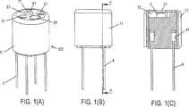
Der erfindungsgemäße Endoskopkopf
Das MID-Formelement
An der distalen Seite und an den Seitenflächen ist das MID-Formelement
An der distalen Stirnfläche besitzt die Kappe
Im am MID-Formelement
Das MID-Formelement
Genauer gesagt sind am MID-Formelement
Nachstehend sind die Leiterbahnen genauer beschrieben.Below the tracks are described in more detail.
Unter Betrachtung von
Beabstandet zur proximalen Endfläche besitzt das MID-Formelement
Zumindest für zwei Zugseilverankerungskörper (in
An der proximalen Seite des Kameraunterbringungsraums, d.h. auf der zweiten Ebene des MID-Formelements
Außerdem weist das MID-Formelement
Nachstehend ist der weitere Aufbau des Endoskopkopfes
In jede seitliche Einbauchung am MID-Formelement
Im vorliegenden Beispiel sind zwei seitliche Einbauchung am MID-Formelement
Die beiden in
Ein solcher Zugseilverankerungskörper
Im vorliegenden Beispiel hat das MID-Formelement
Der Endoskopkopf
Auf dem flächigen Leiterbahnabschnitt
In den Kameraunterbringungsraum ist das Kameramodul
Die Abschirmung
Die Wandstärke der distalen Endfläche der Kappe
Zwischen der proximalen Innenfläche der distalen Endfläche der Kappe
Der Hohlraum
Verfahren zum Herstellen des MID-Formelementes Method for producing the MID molding element
Das MID-Formelement
Beispielsweise kann ein Zweistufenformverfahren angewendet werden.For example, a two-stage molding process can be used.
Zunächst wird ein Kunststoffträger als Grundkörper des MID-Formelementes
Die Formgebung ist dabei weitgehend frei wählbar. Als Endoskopkopfkörper wird das MID-Formelement
Weitere AlternativenOther alternatives
Im vorliegenden Beispiel der
Im vorliegenden Beispiel ist die Kappe
Im vorliegenden Beispiel der
Bei weggelassener Kappe
Im MID-Formelement
Im vorliegenden Beispiel ist ein Kameramodul
Wenn der Sensorbereich für eine andere Sensorart genutzt wird, wie z.B. ein akustischer Sensor, können die von der distalen Endfläche der Vergussmasse vorragenden Abschirmungswandabschnitte auch weggelassen werden.If the sensor area is used for another type of sensor, such as an acoustic sensor, the shield wall portions projecting from the distal end face of the potting compound may also be omitted.
BezugszeichenlisteLIST OF REFERENCE NUMBERS
- 11
- MID-Formelement MID-shaped element
- 1111
- Kappe cap
- 1212
- Hohlraum cavity
- 21–28, 110, 11121-28, 110, 111
- Leiterbahn conductor path
- 33
- LED-Chip LED chip
- 3131
- Öffnung opening
- 44
- Zugseil rope
- 4141
- Zugseilverankerungskörper Zugseilverankerungskörper
- 66
- Kameramodul camera module
- 6161
- Kamerafenster camera window
- 6262
- Kameraabschirmung camera shield
- 6363
- Kameraanschlusskontakte Camera connection contacts
- 77
- Arbeitskanalelement Working channel element
- 7171
- distale Arbeitskanalöffnung distal working channel opening
- 88th
- Spülkanal irrigation channel
- 8181
- distale Spülkanalöffnung distal flushing channel opening
- 102102
- Endoskopkopf endoscope head
- 110110
- Leiterbahnabschnitte Trace sections
- 111111
- Leiterbahnabschnitte für Anschluss des Kameramoduls Track sections for connecting the camera module
Claims (11)
Translated fromGermanPriority Applications (6)
| Application Number | Priority Date | Filing Date | Title |
|---|---|---|---|
| DE102013224683.8ADE102013224683A1 (en) | 2013-12-02 | 2013-12-02 | ENDOSCOPIC HEAD AND ENDOSCOPE |
| CN201480074685.2ACN106061350B (en) | 2013-12-02 | 2014-11-28 | Endoscope head and endoscope |
| PCT/EP2014/075902WO2015082328A1 (en) | 2013-12-02 | 2014-11-28 | Endoscope head and endoscope |
| EP14806228.4AEP3076851B1 (en) | 2013-12-02 | 2014-11-28 | Endoscope head and endoscope |
| US15/101,391US10939803B2 (en) | 2013-12-02 | 2014-11-28 | Endoscope head and endoscope |
| JP2016536635AJP6533787B2 (en) | 2013-12-02 | 2014-11-28 | Endoscope head and endoscope |
Applications Claiming Priority (1)
| Application Number | Priority Date | Filing Date | Title |
|---|---|---|---|
| DE102013224683.8ADE102013224683A1 (en) | 2013-12-02 | 2013-12-02 | ENDOSCOPIC HEAD AND ENDOSCOPE |
Publications (1)
| Publication Number | Publication Date |
|---|---|
| DE102013224683A1true DE102013224683A1 (en) | 2015-06-03 |
Family
ID=52003751
Family Applications (1)
| Application Number | Title | Priority Date | Filing Date |
|---|---|---|---|
| DE102013224683.8AWithdrawnDE102013224683A1 (en) | 2013-12-02 | 2013-12-02 | ENDOSCOPIC HEAD AND ENDOSCOPE |
Country Status (6)
| Country | Link |
|---|---|
| US (1) | US10939803B2 (en) |
| EP (1) | EP3076851B1 (en) |
| JP (1) | JP6533787B2 (en) |
| CN (1) | CN106061350B (en) |
| DE (1) | DE102013224683A1 (en) |
| WO (1) | WO2015082328A1 (en) |
Cited By (3)
| Publication number | Priority date | Publication date | Assignee | Title |
|---|---|---|---|---|
| WO2017025432A1 (en)* | 2015-08-07 | 2017-02-16 | Digital Endoscopy Gmbh | Endoscope head, endoscope, cap and cap forming method |
| WO2018189230A1 (en) | 2017-04-12 | 2018-10-18 | Konstantin Bob | Endoscope head having a pivotable camera and working channel unit |
| DE102019100395A1 (en) | 2019-01-09 | 2020-07-09 | Olympus Winter & Ibe Gmbh | Endoscope connector body and method for mounting an endoscope |
Families Citing this family (34)
| Publication number | Priority date | Publication date | Assignee | Title |
|---|---|---|---|---|
| US10849483B2 (en)* | 2014-09-15 | 2020-12-01 | Vivid Medical, Inc. | Single-use, port deployable articulating endoscope |
| DE102017107106A1 (en) | 2017-04-03 | 2018-10-04 | Hoya Corporation | ENDOSCOPE WITH WIDE ANGLE OPTICS AND WORKING CHANNEL |
| US10485950B2 (en)* | 2017-08-03 | 2019-11-26 | ART MEDICAL Ltd. | Multipurpose cabling |
| CN107822580A (en)* | 2017-10-20 | 2018-03-23 | 上海安清医疗器械有限公司 | First end head, endoscope and its manufacture method of a kind of honeycomb structure |
| CN107802230B (en)* | 2017-11-21 | 2023-09-26 | 江苏西铭医药有限公司 | Direction-adjustable sleeve assembly for endoscope and endoscope device |
| CN112312818B (en)* | 2018-06-28 | 2025-01-21 | 波士顿科学国际有限公司 | Medical device packaging assembly and method thereof |
| CN109717820B (en)* | 2018-12-07 | 2024-06-07 | 上海英诺伟医疗器械股份有限公司 | In-vivo detection device and system based on flexible tube |
| WO2020121435A1 (en)* | 2018-12-12 | 2020-06-18 | オリンパス株式会社 | Endoscope tip and endoscope |
| CN113164021B (en)* | 2018-12-18 | 2024-05-24 | 奥林巴斯株式会社 | Endoscope front end structure and endoscope |
| CN109700432B (en)* | 2018-12-21 | 2024-06-07 | 上海英诺伟医疗器械股份有限公司 | Detection packaging structure and in-vivo detection device based on flexible pipe |
| US11986163B2 (en)* | 2018-12-28 | 2024-05-21 | Hoya Corporation | Endoscope and endoscope system controlled by pair of cable bundles |
| TWI733074B (en)* | 2019-01-09 | 2021-07-11 | 榮晶生物科技股份有限公司 | Microelectronic device and circuit board thereof |
| CN113271837B (en)* | 2019-02-19 | 2024-09-27 | 奥林巴斯株式会社 | Endoscope front end structure and endoscope |
| DE102019105671A1 (en)* | 2019-03-06 | 2020-09-10 | Hoya Corporation | Endoscope with light emitting device and image recording device at the distal end section |
| CN113423321B (en)* | 2019-03-18 | 2024-06-14 | 奥林巴斯株式会社 | Front end frame of endoscope, front end unit and endoscope |
| WO2020188723A1 (en)* | 2019-03-18 | 2020-09-24 | オリンパス株式会社 | Holding frame, endoscope distal end structure, and endoscope |
| CN113382669A (en) | 2019-03-18 | 2021-09-10 | 奥林巴斯株式会社 | Endoscope front end unit |
| WO2020188688A1 (en)* | 2019-03-18 | 2020-09-24 | オリンパス株式会社 | Tip end unit of endoscope |
| CN113365541B (en) | 2019-03-28 | 2024-05-07 | 奥林巴斯株式会社 | Front end frame of endoscope, front end unit and endoscope |
| WO2021181530A1 (en) | 2020-03-10 | 2021-09-16 | オリンパス株式会社 | Endoscope, distal end frame member of endoscope, and insertion part of endoscope |
| WO2021181528A1 (en)* | 2020-03-10 | 2021-09-16 | オリンパス株式会社 | Endoscope, distal end frame member of endoscope, and insertion part of endoscope |
| CN115209780A (en)* | 2020-03-10 | 2022-10-18 | 奥林巴斯株式会社 | Endoscope, distal end frame member of endoscope, and insertion section of endoscope |
| US12268368B2 (en) | 2020-04-30 | 2025-04-08 | Ambu A/S | Medical visualisation device |
| US11931066B2 (en)* | 2021-02-25 | 2024-03-19 | Avent, Inc. | Directly connected smart invasive medical device assembly |
| US11707182B2 (en)* | 2021-03-24 | 2023-07-25 | PacificMD Biotech, LLC | Endoscope and endoscope sheath with diagnostic and therapeutic interfaces |
| JP7500902B2 (en) | 2021-06-29 | 2024-06-18 | オリンパスメディカルシステムズ株式会社 | Imaging unit, endoscope, and method for manufacturing imaging unit |
| WO2023017598A1 (en)* | 2021-08-12 | 2023-02-16 | オリンパスメディカルシステムズ株式会社 | Imaging unit and endoscope applying said imaging unit |
| JP7654088B2 (en)* | 2021-08-19 | 2025-03-31 | オリンパス株式会社 | Image capture module, endoscope, and method for manufacturing image capture module |
| CN114052829B (en)* | 2021-10-11 | 2023-12-19 | 武汉威润八方医疗科技有限公司 | Ureter stone removing device |
| US20230165450A1 (en)* | 2021-11-26 | 2023-06-01 | Altek Biotechnology Corporation | Endoscopic image capturing assembly and endoscopic device therewith |
| US11963667B2 (en) | 2021-11-26 | 2024-04-23 | Altek Biotechnology Corporation | Endoscopic image capturing assembly and endoscopic device therewith |
| WO2024004150A1 (en)* | 2022-06-30 | 2024-01-04 | ジェイソル・メディカル株式会社 | Electronic unit |
| TWI836767B (en)* | 2022-12-02 | 2024-03-21 | 群光電子股份有限公司 | Endoscope module |
| JP7717236B1 (en) | 2024-01-19 | 2025-08-01 | オリンパスメディカルシステムズ株式会社 | Endoscope, imaging module, and method for manufacturing endoscope |
Family Cites Families (86)
| Publication number | Priority date | Publication date | Assignee | Title |
|---|---|---|---|---|
| US3549806A (en) | 1967-05-05 | 1970-12-22 | Gen Electric | Fundamental pitch frequency signal extraction system for complex signals |
| US3605725A (en) | 1968-08-07 | 1971-09-20 | Medi Tech Inc | Controlled motion devices |
| DE6905185U (en) | 1969-02-11 | 1972-04-06 | Bowden Controls Ltd | BOWDEN TRAIN. |
| JPS4827116B1 (en) | 1969-09-12 | 1973-08-18 | ||
| JPS6121041Y2 (en) | 1977-08-04 | 1986-06-24 | ||
| JPS5939128B2 (en) | 1979-10-31 | 1984-09-21 | オリンパス光学工業株式会社 | Endoscope |
| JPS57110228A (en) | 1980-12-26 | 1982-07-09 | Olympus Optical Co | Air and water sending switch apparatus of endoscope |
| US4415767A (en) | 1981-10-19 | 1983-11-15 | Votan | Method and apparatus for speech recognition and reproduction |
| JPS60148536A (en) | 1984-01-17 | 1985-08-05 | オリンパス光学工業株式会社 | Endoscope |
| EP0161834B1 (en)* | 1984-05-04 | 1988-01-07 | Warner-Lambert Technologies, Inc. | Objective head for fibrescopes |
| JPS61118713A (en)* | 1984-11-14 | 1986-06-06 | Olympus Optical Co Ltd | Endoscope |
| US4670009A (en) | 1985-04-16 | 1987-06-02 | American Hospital Supply Corp. | Backform inserts for catheter |
| JPS62227312A (en) | 1986-03-27 | 1987-10-06 | 旭光学工業株式会社 | Mount structure of curving operation wire of endoscope |
| US5245133A (en) | 1991-10-15 | 1993-09-14 | Thomas & Betts Corporation | Moisture-resistant cable splice and sealing structure thereof |
| JP3219521B2 (en) | 1993-03-01 | 2001-10-15 | オリンパス光学工業株式会社 | Endoscope |
| US5569157A (en) | 1993-05-07 | 1996-10-29 | Olympus Optical Co., Ltd. | Endoscope |
| US5588950A (en) | 1994-07-11 | 1996-12-31 | Asahi Kogaku Kogyo Kabushiki Kaisha | Portable endoscope system |
| US5630419A (en) | 1994-12-20 | 1997-05-20 | Tetrad Corporation | Sealing connector for multiconductor cables |
| DE19627016C1 (en) | 1996-07-04 | 1998-02-12 | Etm Endotech Gmbh Medizintechn | Flexible endoscope |
| US5845241A (en) | 1996-09-04 | 1998-12-01 | Hughes Electronics Corporation | High-accuracy, low-distortion time-frequency analysis of signals using rotated-window spectrograms |
| JPH10225439A (en) | 1997-02-17 | 1998-08-25 | Olympus Optical Co Ltd | Image pickup device for endoscope |
| DE19731965A1 (en) | 1997-07-24 | 1999-01-28 | Etm Endotech Gmbh Medizintechn | Air / water and suction valves on endoscopes |
| US5968056A (en)* | 1997-11-13 | 1999-10-19 | Boston Scientific Corporation | Device and method for severing lesions |
| DE19840986A1 (en) | 1998-09-08 | 2000-03-09 | Etm Endoskopische Technik Gmbh | Quick release for an endoscope |
| DE19843337A1 (en) | 1998-09-22 | 2000-03-23 | Sram De Gmbh | Cable control adjustment mechanism for bicycle has fewer components than prior art and retains lubricating grease |
| US6734893B1 (en) | 1998-12-04 | 2004-05-11 | Olympus Winter & Ibe Gmbh | Endoscopy illumination system for stroboscopy |
| JP3179426B2 (en)* | 1998-12-21 | 2001-06-25 | オリンパス光学工業株式会社 | Endoscope device |
| US6547722B1 (en) | 1999-07-13 | 2003-04-15 | Olympus Optical Co., Ltd. | Endoscope having resistance to high-temperature and high-pressure steam |
| JP2001061772A (en) | 1999-08-30 | 2001-03-13 | Fuji Photo Optical Co Ltd | Fluid controller for endoscope |
| JP3488170B2 (en) | 2000-03-21 | 2004-01-19 | オリンパス株式会社 | Endoscope |
| JP3821206B2 (en) | 2000-09-29 | 2006-09-13 | フジノン株式会社 | Waterproof cap for connector of endoscope |
| JP2002160691A (en) | 2000-11-28 | 2002-06-04 | Nissin Kogyo Co Ltd | Brake system for bar handle vehicles |
| JP2002238831A (en) | 2001-02-16 | 2002-08-27 | Fuji Photo Optical Co Ltd | Endoscope |
| JP2002291699A (en) | 2001-03-30 | 2002-10-08 | Asahi Optical Co Ltd | Endoscope system for vocal fold observation |
| US20060199999A1 (en) | 2001-06-29 | 2006-09-07 | Intuitive Surgical Inc. | Cardiac tissue ablation instrument with flexible wrist |
| US6793622B2 (en) | 2001-09-05 | 2004-09-21 | Olympus Optical Co., Ltd. | Electric bending endoscope |
| JP2003190085A (en) | 2001-12-25 | 2003-07-08 | Olympus Optical Co Ltd | Electrical connector |
| JP2004049891A (en) | 2002-05-29 | 2004-02-19 | Olympus Corp | Endoscope apparatus |
| JP2007111541A (en) | 2002-05-29 | 2007-05-10 | Olympus Corp | Endoscope apparatus and connecting device for endoscope |
| US7179223B2 (en) | 2002-08-06 | 2007-02-20 | Olympus Optical Co., Ltd. | Endoscope apparatus having an internal channel |
| DE10254609B4 (en)* | 2002-11-22 | 2017-12-07 | Stm Medizintechnik Starnberg Gmbh | endoscope head |
| DE10320228A1 (en) | 2003-05-05 | 2004-11-25 | Stm Medizintechnik Starnberg Gmbh | endoscope shaft |
| JP2005006769A (en)* | 2003-06-17 | 2005-01-13 | Olympus Corp | Encapsulated endoscope |
| US7842028B2 (en) | 2005-04-14 | 2010-11-30 | Cambridge Endoscopic Devices, Inc. | Surgical instrument guide device |
| JP4461100B2 (en) | 2004-02-16 | 2010-05-12 | オリンパス株式会社 | Endoscope system |
| ES2552252T3 (en) | 2004-03-23 | 2015-11-26 | Boston Scientific Limited | Live View System |
| JP2005304586A (en) | 2004-04-19 | 2005-11-04 | Pentax Corp | The tip of a side-viewing endoscope |
| US7811277B2 (en)* | 2004-09-30 | 2010-10-12 | Boston Scientific Scimed, Inc. | Steerable device and system |
| JP4661190B2 (en) | 2004-11-30 | 2011-03-30 | 富士フイルム株式会社 | Cleaning adapter |
| CN2762381Y (en) | 2004-12-17 | 2006-03-01 | 亮泰企业股份有限公司 | Waterproof structure of AC power plug and socket |
| US20060252993A1 (en) | 2005-03-23 | 2006-11-09 | Freed David I | Medical devices and systems |
| US8287449B2 (en) | 2005-05-26 | 2012-10-16 | Ars Co., Ltd. | Endoscope device |
| WO2007002526A1 (en) | 2005-06-24 | 2007-01-04 | Everest Vit, Inc. | Insertion tube storage carousel |
| DE102005041454A1 (en) | 2005-08-31 | 2007-03-01 | Karl Storz Gmbh & Co. Kg | Endoscope, has bowden cable that is mounted proximal-laterally by clamping grippers, where plug-in depth of towing cable of bowden cable is limited in clamping grippers by pressing unit, which acts on towing cable and clamping grippers |
| AU2007201204B2 (en) | 2006-03-23 | 2012-07-12 | Ethicon Endo-Surgery, Inc. | Articulating endoscopic accessory channel |
| US8236010B2 (en) | 2006-03-23 | 2012-08-07 | Ethicon Endo-Surgery, Inc. | Surgical fastener and cutter with mimicking end effector |
| JP4812515B2 (en) | 2006-05-26 | 2011-11-09 | 富士フイルム株式会社 | Cleaning adapter |
| US7615067B2 (en) | 2006-06-05 | 2009-11-10 | Cambridge Endoscopic Devices, Inc. | Surgical instrument |
| JP2008119057A (en)* | 2006-11-08 | 2008-05-29 | Matsushita Electric Works Ltd | Capsule-type imaging device |
| KR200444134Y1 (en) | 2007-07-09 | 2009-04-10 | 유메디칼 주식회사 | Laryngeal Stroboscope Using Voice Signal |
| US9005238B2 (en) | 2007-08-23 | 2015-04-14 | Covidien Lp | Endoscopic surgical devices |
| ES2356497T3 (en) | 2007-08-23 | 2011-04-08 | Tyco Healthcare Group Lp | ENDOSCOPIC SURGICAL DEVICES. |
| JP2009201762A (en) | 2008-02-28 | 2009-09-10 | Hoya Corp | Endoscope and photographing module |
| EP2119390B1 (en) | 2008-05-16 | 2011-07-20 | FUJIFILM Corporation | Connector for endoscope |
| ES2551131T3 (en)* | 2008-12-10 | 2015-11-16 | Ambu A/S | Endoscope that has a camera receptacle and procedure for manufacturing a camera receptacle |
| US8700129B2 (en) | 2008-12-31 | 2014-04-15 | St. Jude Medical, Atrial Fibrillation Division, Inc. | Devices and methods for catheter localization |
| US8512371B2 (en)* | 2009-10-06 | 2013-08-20 | Covidien Lp | Jaw, blade and gap manufacturing for surgical instruments with small jaws |
| DE102009060500B4 (en) | 2009-12-22 | 2015-12-17 | Xion Gmbh | A method for stroboscopically examining repetitive processes and arrangement for operating this method |
| WO2011108157A1 (en) | 2010-03-05 | 2011-09-09 | オリンパスメディカルシステムズ株式会社 | Endoscope |
| JPWO2011114772A1 (en) | 2010-03-16 | 2013-06-27 | オリンパスメディカルシステムズ株式会社 | Connector receiver, connector connection system |
| TW201201641A (en) | 2010-06-18 | 2012-01-01 | Sun Wei Ren | Micro sensor |
| DE102010034623A1 (en) | 2010-08-17 | 2012-02-23 | Olympus Winter & Ibe Gmbh | Generic endoscope used for e.g. laparoscopic surgery, has video camera, electrical conductors and contact device that are enclosed in cast structure of main portion |
| DE102010039731A1 (en)* | 2010-08-25 | 2012-03-01 | Olympus Winter & Ibe Gmbh | Electrical connector and endoscopy system |
| JP5552014B2 (en) | 2010-09-29 | 2014-07-16 | 富士フイルム株式会社 | Endoscope suction button |
| JP4897117B1 (en) | 2010-12-24 | 2012-03-14 | オリンパス株式会社 | Endoscope device |
| WO2012089671A1 (en) | 2010-12-29 | 2012-07-05 | Skype | Dynamical adaptation of data encoding dependent on cpu load |
| DE102012100933A1 (en) | 2011-02-04 | 2012-08-09 | Schott Ag | Detention system for connection of two subject matters, has adhesive layer comprising bionic structure that is present in form of spatulas and producible over embossing method, where adhesive layer is applied on substrate |
| JP5851118B2 (en) | 2011-05-25 | 2016-02-03 | オリンパス株式会社 | Endoscope device |
| CN103717120B (en) | 2011-08-03 | 2015-12-23 | 奥林巴斯株式会社 | Line haulage gear and endoscope apparatus |
| CN102401995B (en) | 2011-11-18 | 2013-05-29 | 无锡微奥科技有限公司 | Micro optical probe of endoscope |
| JP5883683B2 (en) | 2012-03-02 | 2016-03-15 | Hoya株式会社 | Optical scanning endoscope |
| CN202748535U (en)* | 2012-08-16 | 2013-02-20 | 宁波舜宇光电信息有限公司 | Industrial endoscope |
| WO2014038638A1 (en) | 2012-09-05 | 2014-03-13 | オリンパスメディカルシステムズ株式会社 | Ultrasonic endoscope |
| US9549666B2 (en)* | 2012-11-10 | 2017-01-24 | Curvo Medical, Inc. | Coaxial micro-endoscope |
| CN103211566B (en) | 2013-04-17 | 2014-12-10 | 杭州安杰思医学科技有限公司 | Endoscope with water injection and gas injection selecting button |
| WO2015026557A1 (en) | 2013-08-20 | 2015-02-26 | Cook Medical Technologies Llc | Endoscope mountable visualization device and handle |
- 2013
- 2013-12-02DEDE102013224683.8Apatent/DE102013224683A1/ennot_activeWithdrawn
- 2014
- 2014-11-28WOPCT/EP2014/075902patent/WO2015082328A1/enactiveApplication Filing
- 2014-11-28USUS15/101,391patent/US10939803B2/enactiveActive
- 2014-11-28EPEP14806228.4Apatent/EP3076851B1/enactiveActive
- 2014-11-28JPJP2016536635Apatent/JP6533787B2/enactiveActive
- 2014-11-28CNCN201480074685.2Apatent/CN106061350B/enactiveActive
Cited By (11)
| Publication number | Priority date | Publication date | Assignee | Title |
|---|---|---|---|---|
| WO2017025432A1 (en)* | 2015-08-07 | 2017-02-16 | Digital Endoscopy Gmbh | Endoscope head, endoscope, cap and cap forming method |
| CN113475998A (en)* | 2015-08-07 | 2021-10-08 | 数字内窥镜检查有限公司 | Endoscope with a detachable handle |
| US11278187B2 (en) | 2015-08-07 | 2022-03-22 | Digital Endoscopy Gmbh | Endoscope head |
| US12082778B2 (en) | 2015-08-07 | 2024-09-10 | Digital Endoscopy Gmbh | Endoscope head |
| WO2018189230A1 (en) | 2017-04-12 | 2018-10-18 | Konstantin Bob | Endoscope head having a pivotable camera and working channel unit |
| DE102017107978A1 (en)* | 2017-04-12 | 2018-10-18 | Konstantin Bob | Endoscope with swiveling camera and working channel unit |
| DE102017107978B4 (en) | 2017-04-12 | 2019-01-10 | Konstantin Bob | Endoscope head with swiveling camera and working channel unit |
| US12042122B2 (en) | 2017-04-12 | 2024-07-23 | Konstantin Bob | Endoscope head having a pivotable camera and working channel unit |
| DE102019100395A1 (en) | 2019-01-09 | 2020-07-09 | Olympus Winter & Ibe Gmbh | Endoscope connector body and method for mounting an endoscope |
| WO2020144107A1 (en) | 2019-01-09 | 2020-07-16 | Olympus Winter & Ibe Gmbh | Connection body of an endoscope and method for assembling an endoscope |
| US12004713B2 (en) | 2019-01-09 | 2024-06-11 | Olympus Winter & Ibe Gmbh | Connection body of an endoscope and method for assembling an endoscope |
Also Published As
| Publication number | Publication date |
|---|---|
| CN106061350B (en) | 2019-10-29 |
| US20170127915A1 (en) | 2017-05-11 |
| WO2015082328A1 (en) | 2015-06-11 |
| EP3076851B1 (en) | 2022-08-03 |
| JP6533787B2 (en) | 2019-06-19 |
| CN106061350A (en) | 2016-10-26 |
| JP2017505154A (en) | 2017-02-16 |
| EP3076851A1 (en) | 2016-10-12 |
| US10939803B2 (en) | 2021-03-09 |
Similar Documents
| Publication | Publication Date | Title |
|---|---|---|
| DE102013224683A1 (en) | ENDOSCOPIC HEAD AND ENDOSCOPE | |
| DE102006001290C5 (en) | Housing termination for electronics housings and method for its manufacture | |
| EP1182959B1 (en) | Modular image recording system and method of assembling such a modular image recording system | |
| EP2240949B1 (en) | Sensor | |
| DE102007012818B4 (en) | Semiconductor device with connections | |
| DE102004056946A1 (en) | Image pick-up module and method of assembling an image pick-up module | |
| DE102004046725B4 (en) | Housing for a light grid | |
| DE102006006726A1 (en) | Electrical connector | |
| EP2520142B1 (en) | Sensor with a housing, and method for the production thereof | |
| DE102014009103B4 (en) | TORQUE SENSOR COVER | |
| DE102004026210B4 (en) | Device for detecting a physical quantity and housing for a device for measuring a physical quantity | |
| EP1347233A2 (en) | Signal column | |
| DE102009056212A1 (en) | An electronic component manufactured by injection molding, method and tool for manufacturing the same, and electronic apparatus for using the same | |
| DE102009012538B4 (en) | Photocell and method for producing a light barrier | |
| EP2730952B1 (en) | Light grid | |
| DE102004017899A1 (en) | Position sensor arrangement with a plurality of magnetic field-sensitive sensors arranged in a row, in particular Hall sensors | |
| EP3408865B1 (en) | Device carrier comprising contact chambers for an optoelectronic apparatus | |
| DE19901913A1 (en) | Electrical device with a housing | |
| EP2031356A2 (en) | Sensor | |
| EP2192420A1 (en) | Optical send and receive component and sensor with such | |
| DE60221363T2 (en) | Magnetostrictive encoder | |
| EP4560354A1 (en) | Method for manufacturing a measuring unit and measuring unit | |
| HK1261106B (en) | Device carrier comprising contact chambers for an optoelectronic apparatus | |
| WO2020064540A1 (en) | Optoelectronic device and connection element | |
| DE202018006073U1 (en) | Component carrier and injection mold |
Legal Events
| Date | Code | Title | Description |
|---|---|---|---|
| R086 | Non-binding declaration of licensing interest | ||
| R012 | Request for examination validly filed | ||
| R016 | Response to examination communication | ||
| R119 | Application deemed withdrawn, or ip right lapsed, due to non-payment of renewal fee |