DE102013221664A1 - Wire-wound inductor of a switched-mode power supply and switched-mode power supply with the wire-wound inductor - Google Patents
Wire-wound inductor of a switched-mode power supply and switched-mode power supply with the wire-wound inductorDownload PDFInfo
- Publication number
- DE102013221664A1 DE102013221664A1DE102013221664.5ADE102013221664ADE102013221664A1DE 102013221664 A1DE102013221664 A1DE 102013221664A1DE 102013221664 ADE102013221664 ADE 102013221664ADE 102013221664 A1DE102013221664 A1DE 102013221664A1
- Authority
- DE
- Germany
- Prior art keywords
- buffering pad
- magnetic core
- wound inductor
- winding
- wire wound
- Prior art date
- Legal status (The legal status is an assumption and is not a legal conclusion. Google has not performed a legal analysis and makes no representation as to the accuracy of the status listed.)
- Withdrawn
Links
- 230000003139buffering effectEffects0.000claimsabstractdescription82
- 238000004804windingMethods0.000claimsabstractdescription40
- 239000013013elastic materialSubstances0.000claimsdescription9
- 239000004020conductorSubstances0.000claimsdescription6
- 230000005389magnetismEffects0.000claimsdescription4
- 230000001052transient effectEffects0.000description3
- 229910000838Al alloyInorganic materials0.000description2
- XEEYBQQBJWHFJM-UHFFFAOYSA-NIronChemical compound[Fe]XEEYBQQBJWHFJM-UHFFFAOYSA-N0.000description2
- 230000000694effectsEffects0.000description2
- 238000004519manufacturing processMethods0.000description2
- 239000000463materialSubstances0.000description2
- 229910052751metalInorganic materials0.000description2
- 239000002184metalSubstances0.000description2
- BUHVIAUBTBOHAG-FOYDDCNASA-N(2r,3r,4s,5r)-2-[6-[[2-(3,5-dimethoxyphenyl)-2-(2-methylphenyl)ethyl]amino]purin-9-yl]-5-(hydroxymethyl)oxolane-3,4-diolChemical compoundCOC1=CC(OC)=CC(C(CNC=2C=3N=CN(C=3N=CN=2)[C@H]2[C@@H]([C@H](O)[C@@H](CO)O2)O)C=2C(=CC=CC=2)C)=C1BUHVIAUBTBOHAG-FOYDDCNASA-N0.000description1
- 229910000531Co alloyInorganic materials0.000description1
- RYGMFSIKBFXOCR-UHFFFAOYSA-NCopperChemical compound[Cu]RYGMFSIKBFXOCR-UHFFFAOYSA-N0.000description1
- 229910001030Iron–nickel alloyInorganic materials0.000description1
- 229910001209Low-carbon steelInorganic materials0.000description1
- 229910000676Si alloyInorganic materials0.000description1
- BQCADISMDOOEFD-UHFFFAOYSA-NSilverChemical compound[Ag]BQCADISMDOOEFD-UHFFFAOYSA-N0.000description1
- QVYYOKWPCQYKEY-UHFFFAOYSA-N[Fe].[Co]Chemical compound[Fe].[Co]QVYYOKWPCQYKEY-UHFFFAOYSA-N0.000description1
- 230000006978adaptationEffects0.000description1
- KCZFLPPCFOHPNI-UHFFFAOYSA-Nalumane;ironChemical compound[AlH3].[Fe]KCZFLPPCFOHPNI-UHFFFAOYSA-N0.000description1
- 229910052782aluminiumInorganic materials0.000description1
- XAGFODPZIPBFFR-UHFFFAOYSA-NaluminiumChemical compound[Al]XAGFODPZIPBFFR-UHFFFAOYSA-N0.000description1
- 230000004323axial lengthEffects0.000description1
- 230000005489elastic deformationEffects0.000description1
- 229910052742ironInorganic materials0.000description1
- XWHPIFXRKKHEKR-UHFFFAOYSA-Niron siliconChemical compound[Si].[Fe]XWHPIFXRKKHEKR-UHFFFAOYSA-N0.000description1
- -1iron-silicon-aluminumChemical compound0.000description1
- 239000000696magnetic materialSubstances0.000description1
- 230000005415magnetizationEffects0.000description1
- 239000011159matrix materialSubstances0.000description1
- 238000012986modificationMethods0.000description1
- 230000004048modificationEffects0.000description1
- 230000001105regulatory effectEffects0.000description1
Images


Classifications
- H—ELECTRICITY
- H01—ELECTRIC ELEMENTS
- H01F—MAGNETS; INDUCTANCES; TRANSFORMERS; SELECTION OF MATERIALS FOR THEIR MAGNETIC PROPERTIES
- H01F27/00—Details of transformers or inductances, in general
- H01F27/33—Arrangements for noise damping
- H—ELECTRICITY
- H01—ELECTRIC ELEMENTS
- H01F—MAGNETS; INDUCTANCES; TRANSFORMERS; SELECTION OF MATERIALS FOR THEIR MAGNETIC PROPERTIES
- H01F5/00—Coils
- H01F5/02—Coils wound on non-magnetic supports, e.g. formers
Landscapes
- Engineering & Computer Science (AREA)
- Power Engineering (AREA)
- Coils Or Transformers For Communication (AREA)
Abstract
Translated fromGermanDescription
Translated fromGermanKREUZBEZUG AUF BETREFFENDE ANMELDUNGENCROSS-REFERENCE TO RELATED APPLICATIONS
Diese Anmeldung beansprucht die Priorität der
GEBIET DER ERFINDUNGFIELD OF THE INVENTION
Die vorliegende Erfindung betrifft im Allgemeinen ein Schaltnetzteil und insbesondere einen drahtgewickelten (wirewound) Induktor des Schaltnetzteils und ein Schaltnetzteil mit dem drahtgewickelten Induktor.The present invention generally relates to a switched-mode power supply and, more particularly, to a wirewound inductor of the switched mode power supply and to a switched mode power supply having the wire wound inductor.
HINTERGRUNDBACKGROUND
Das Schaltnetzteil hat schrittweise das lineare Netzteil ersetzt und ist auf verschiedene elektronische Produkte aufgrund seiner vielen Vorteile, wie etwa kleines Volumen, niedriges Gewicht und großer Bereich der Eingangsspannung, ein niedriger Wärmeverbrauch usw., angewendet worden. Die Hauptkomponenten, welche in dem Schaltnetzteil umfasst sind, weisen einen drahtgewickelten bzw. drahtgewundenen Induktor auf. Der Strom in der Wicklung des drahtgewickelten Induktors des Schaltnetzteils übersteigt gewöhnlich 20A und es ist wohlbekannt, dass sich die transiente Last (transient loading) des Schaltnetzteils schnell ändert und es somit zu einem offensichtlichen Magnetostriktions-Phänomen führt, welches in dem magnetischen Körper (d. h. der magnetische Kern des drahtgewickelten Induktors) erzeugt ist. Die Magnetostriktion bezieht sich auf die Ausdehnungs-Änderungen in jeder Richtung aufgrund der Änderung der Magnetisierung.The switching power supply has gradually replaced the linear power supply and has been applied to various electronic products because of its many advantages such as small volume, low weight and wide range of input voltage, low heat consumption, etc. The main components included in the switching power supply include a wire wound inductor. The current in the winding of the wirewound inductor of the switched mode power supply usually exceeds 20A and it is well known that the transient loading of the switched mode power supply changes rapidly, thus leading to an obvious magnetostriction phenomenon occurring in the magnetic body (ie magnetic core of the wire wound inductor) is generated. The magnetostriction refers to the expansion changes in each direction due to the change in magnetization.
Das Magnetostriktions-Phänomen führt zu einer natürlichen Vibration in dem magnetischen Körper und führt dann zu einer Kollision zwischen dem magnetischen Körper und der Wicklung, während diese Vibration und Kollision das störende Geräusch in dem Schaltnetzteil erzeugen. Wie vorher erwähnt ist, gehört die Vibration, welche mittels des Magnetostriktions-Phänomens induziert ist, zu einem unausweichlichen Phänomen, welches in dem magnetischen Körper auftritt. Gewöhnlich ist der Dezibel-Wert des Geräusches, welches mittels der Kollision erzeugt ist, größer als das Geräusch, welches mittels der Vibration erzeugt ist, und daher kann der Dezibel-Wert des Geräusches in dem Schaltnetzteil effektiv dadurch vermindert werden, dass das Geräusch, welches mittels der Kollision erzeugt ist, vermindert wird.The magnetostriction phenomenon results in natural vibration in the magnetic body and then causes a collision between the magnetic body and the coil, while this vibration and collision generate the disturbing noise in the switching power supply. As mentioned previously, the vibration induced by the magnetostriction phenomenon belongs to an inevitable phenomenon which occurs in the magnetic body. Usually, the decibel value of the noise generated by the collision is larger than the noise generated by the vibration, and therefore, the decibel value of the noise in the switching power supply can be effectively reduced by reducing the noise is generated by the collision is reduced.
Daher gibt es einen Bedarf zum Bereitstellen eines drahtgewickelten Induktors eines Schaltnetzteils und eines Schaltnetzteils mit dem drahtgewickelten Induktor, um das obige Problem in dem Stand der Technik zu lösen.Therefore, there is a need to provide a wire wound inductor of a switched mode power supply and a switched mode power supply with the wire wound inductor to solve the above problem in the related art.
ZUSAMMENFASSUNG DER ERFINDUNGSUMMARY OF THE INVENTION
Um das obige Problem zu lösen, ist ein drahtgewickelter Induktor eines Schaltnetzteils gemäß einem Aspekt der vorliegenden Erfindung bereitgestellt, welcher einen magnetischen Kern und eine Wicklung, welche auf den elektrischen Kern gewickelt ist, aufweist. Ein Pufferungs-Dämpfer bzw. Pufferungs-Polster (buffering cushion) ist zwischen dem magnetischen Kern und der Wicklung angeordnet. Das Pufferungs-Polster ist aus einem elastischen Material gebildet und die Dicke des Pufferungs-Polsters ist größer als ein radialer Abstand zwischen dem magnetischen Kern und der Wicklung.In order to solve the above problem, there is provided a wirewound inductor of a switching power supply according to an aspect of the present invention, which has a magnetic core and a winding wound on the electric core. A buffering cushion is disposed between the magnetic core and the winding. The buffering pad is formed of an elastic material and the thickness of the buffering pad is greater than a radial distance between the magnetic core and the winding.
Vorzugsweise ist das Pufferungs-Polster aus einem elastischen Material mit einer hohen Temperatur-Widerstandsfähigkeit gebildet.Preferably, the buffering pad is formed of an elastic material having a high temperature resistance.
Vorzugsweise deckt das Pufferungs-Polster eine Fläche des magnetischen Kerns entsprechend der Wicklung ab.Preferably, the buffering pad covers an area of the magnetic core corresponding to the winding.
Vorzugsweise ist das Pufferungs-Polster röhrenförmig.Preferably, the buffering pad is tubular.
Vorzugsweise ist das Pufferungs-Polster mit einem axialen Schlitz bereitgestellt, welcher sich entlang einer axialen Richtung des drahtgewickelten Induktors erstreckt.Preferably, the buffering pad is provided with an axial slot extending along an axial direction of the wire wound inductor.
Vorzugsweise ist eine Breite des axialen Schlitzes kleiner als oder gleich wie 3/4 eines Umfangs des Pufferungs-Polsters.Preferably, a width of the axial slot is less than or equal to 3/4 of a circumference of the buffering pad.
Vorzugsweise ist das Pufferungs-Polster mit einem Umfangs-Schlitz bereitgestellt, welcher sich entlang einer Umfangsrichtung des drahtgewickelten Induktors erstreckt.Preferably, the buffering pad is provided with a circumferential slot extending along a circumferential direction of the wire wound inductor.
Vorzugsweise ist das Pufferungs-Polster mit einer Mehrzahl von Umfangs-Schlitzen bereitgestellt, wobei die Mehrzahl von Umfangs-Schlitzen uniform verteilt sind.Preferably, the buffering pad is provided with a plurality of circumferential slots, wherein the plurality of circumferential slots are uniformly distributed.
Vorzugsweise ist das Pufferungs-Polster mit einer Mehrzahl von Wärme-dissipierenden Öffnungen bereitgestellt.Preferably, the buffering pad is provided with a plurality of heat-dissipating openings.
Vorzugsweise ist das Pufferungs-Polster aus einem schlechten Leiter von Magnetismus gebildet.Preferably, the buffering pad is formed from a bad conductor of magnetism.
Ein Schaltnetz-Werk ist ferner gemäß einem anderen Aspekt der vorliegenden Erfindung bereitgestellt, welches einen drahtgewickelten Induktor hat. Der drahtgebundene Induktor weist einen magnetischen Kern und eine Wicklung, welche auf dem magnetischen Kern gewickelt ist, auf. Ein Pufferungs-Polster ist zwischen dem magnetischen Kern und der Wicklung angeordnet. Das Pufferungs-Polster ist aus einem elastischen Material gebildet und eine Dicke des Pufferungs-Polsters ist größer als ein radialer Abstand zwischen dem magnetischen Kern und der Wicklung.A switching power plant is further provided in accordance with another aspect of the present invention having a wirewound inductor. The wired inductor has a magnetic core and a winding wound on the magnetic core. A buffering pad is disposed between the magnetic core and the winding. The buffering pad is formed of an elastic material and a thickness of the buffering pad is greater than a radial distance between the magnetic core and the winding.
Vorzugsweise ist das Pufferungs-Polster aus einem elastischen Material mit einer hohen Temperatur-Widerstandsfähigkeit gebildet.Preferably, the buffering pad is formed of an elastic material having a high temperature resistance.
Vorzugsweise deckt das Pufferungs-Polster eine Fläche des magnetischen Kerns entsprechend der Wicklung ab.Preferably, the buffering pad covers an area of the magnetic core corresponding to the winding.
Vorzugsweise ist das Pufferungs-Polster röhrenförmig.Preferably, the buffering pad is tubular.
Vorzugsweise ist das Pufferungs-Polster mit einem axialen Schlitz bereitgestellt, welcher sich entlang einer axialen Richtung des drahtgewickelten Induktors erstreckt.Preferably, the buffering pad is provided with an axial slot extending along an axial direction of the wire wound inductor.
Vorzugsweise ist eine Breite des axialen Schlitzes kleiner als oder gleich wie 3/4 eines Umfangs des Pufferungs-Polsters.Preferably, a width of the axial slot is less than or equal to 3/4 of a circumference of the buffering pad.
Vorzugsweise ist das Pufferungs-Polster mit einem Umfangs-Schlitz bereitgestellt, welcher sich entlang einer Umfangsrichtung des drahtgewickelten Induktors erstreckt.Preferably, the buffering pad is provided with a circumferential slot extending along a circumferential direction of the wire wound inductor.
Vorzugsweise ist das Pufferungs-Polster mit einer Mehrzahl von Umfangs-Schlitzen bereitgestellt, wobei die Mehrzahl von Umfangs-Schlitzen uniform verteilt sind.Preferably, the buffering pad is provided with a plurality of circumferential slots, wherein the plurality of circumferential slots are uniformly distributed.
Vorzugsweise ist das Pufferungs-Polster mit einer Mehrzahl von Wärme-dissipierenden Öffnungen bereitgestellt.Preferably, the buffering pad is provided with a plurality of heat-dissipating openings.
Vorzugsweise ist das Pufferungs-Polster aus einem schlechten Leiter von Magnetismus gebildet.Preferably, the buffering pad is formed from a bad conductor of magnetism.
Der drahtgewickelte Induktor, welcher durch die vorliegende Erfindung bereitgestellt ist, ist mit dem Pufferungs-Polster zwischen dem magnetischen Kern und der Wicklung bereitgestellt, um die Ausdehnungs-Änderungen des magnetischen Kerns, welche durch das Magnetostriktions-Phänomen verursacht sind, zu absorbieren und somit sind die relativen Positionen der Komponenten aufrechterhalten, die Kollision zwischen dem magnetischen Kern und der Wicklung kann verhindert werden und dann ist das Geräusch vermindert.The wire wound inductor provided by the present invention is provided with the buffering pad between the magnetic core and the winding to absorb and thus are the expansion changes of the magnetic core caused by the magnetostriction phenomenon maintain the relative positions of the components, the collision between the magnetic core and the winding can be prevented and then the noise is reduced.
Eine Serie von vereinfachten Konzeptionen sind in die Zusammenfassung der Erfindung inkorporiert, welche ferner in größerem Detail in der detaillierten Beschreibung beschrieben werden. Die Zusammenfassung der Erfindung impliziert weder, dass sie beabsichtigt ist, die essentiellen Merkmale und notwendigen technischen Merkmale der zu schützenden technischen Lösung zu begrenzen, noch impliziert sie, dass es beabsichtigt ist, den Schutz-Geltungsbereich der zu schützenden technischen Lösung zu definieren.A series of simplified conceptions are incorporated into the summary of the invention, which are further described in greater detail in the detailed description. The summary of the invention neither implies that it is intended to limit the essential features and necessary technical features of the technical solution to be protected, nor does it imply that it is intended to define the scope of protection of the technical solution to be protected.
Vorteile und Merkmale der vorliegenden Erfindung werden unten im Zusammenhang mit den begleitenden Zeichnungen im Detail beschrieben.Advantages and features of the present invention will be described below in detail in conjunction with the accompanying drawings.
KURZE BESCHREIBUNG DER ZEICHNUNGENBRIEF DESCRIPTION OF THE DRAWINGS
Die folgenden Zeichnungen der vorliegenden Erfindung werden als ein Teil der vorliegenden Erfindung zum Verstehen der vorliegenden Erfindung benutzt, wobei die Ausführungsformen und Beschreibungen davon in den Zeichnungen zum Erklären des Prinzips der vorliegenden Erfindung illustriert sind. In den ZeichnungenThe following drawings of the present invention are used as a part of the present invention for understanding the present invention, the embodiments and descriptions of which are illustrated in the drawings for explaining the principle of the present invention. In the drawings
ist
ist
DETAILLIERTE BESCHREIBUNGDETAILED DESCRIPTION
Eine Fülle von spezifischen Details sind präsentiert, um so ein durchgängigeres Verständnis der vorliegenden Erfindung in der Beschreibung unten bereitzustellen. Die vorliegende Erfindung kann jedoch ohne eines oder mehrere dieser Details implementiert werden, wie für den Fachmann in der Technik offensichtlich ist. In anderen Beispielen sind einige der technischen Merkmale, welche in der Technik bekannt sind, nicht beschrieben, um so Konfusionen mit der vorliegenden Erfindung zu vermeiden.A wealth of specific details are presented so as to provide a more thorough understanding of the present invention in the description below. However, the present invention may be implemented without one or more of these details, as will be apparent to those skilled in the art. In other examples, some of the technical features known in the art are not described so as to avoid confusion with the present invention.
Gemäß einem Aspekt der vorliegenden Erfindung ist ein drahtgewickelter Induktor eines Schaltnetzteils (hierin nachfolgend als der drahtgewickelte Induktor bezeichnet) bereitgestellt.
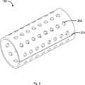
Wie in
Um auf das Magnetostriktions-Phänomen zu adaptieren, welches in dem magnetischen Kern
Auf der einen Seite läuft gewöhnlich der Strom mit einer größeren Strom-Intensität in der Wicklung
Um Materialien einzusparen und Kosten zu vermindern, kann bzw. braucht das Pufferungs-Polster
Während der Herstellung des drahtgewickelten Induktors wird der magnetische Kern
Gemäß einem Aspekt der vorliegenden Erfindung kann das Pufferungs-Polster
Gemäß einem anderen Aspekt der vorliegenden Erfindung kann das Pufferungs-Polster
Wie oben erwähnt ist, können der magnetische Kern
Um zu vermeiden, dass das Pufferungs-Polster
Gemäß einem anderen Aspekt der vorliegenden Erfindung ist ferner ein Schaltnetzteil bereitgestellt. Das Schaltnetzteil weist irgendeine Art von drahtgewickeltem Induktor, welcher oben erwähnt ist, auf. Die Form und die Struktur jeder Komponente, welche in dem drahtgewickelten Induktor umfasst ist, können sich auf die Beschreibung des entsprechenden oben erwähnten Teiles beziehen und sind nicht länger im Detail hierin beschrieben.According to another aspect of the present invention, there is further provided a switching power supply. The switching power supply includes any type of wire wound inductor mentioned above. The shape and structure of each component included in the wirewound inductor may be related to the description of the corresponding part mentioned above and are no longer described in detail herein.
Zusammenfassend ist der mittels der vorliegenden Erfindung bereitgestellte drahtgewickelte Induktor mit einem Pufferungs-Polster zwischen dem magnetischen Kern und der Wicklung bereitgestellt, um die Dimensions-Änderungen des magnetischen Kerns, welche mittels des Magnetostriktions-Phänomen verursacht sind, zu absorbieren und somit sind die relativen Positionen der Komponenten aufrechterhalten, die Kollision zwischen dem magnetischen Kern und der Wicklung kann verhindert werden und dann ist das Geräusch vermindert.In summary, the wirewound inductor provided with the present invention is provided with a buffering pad between the magnetic core and the coil to absorb the dimensional changes of the magnetic core caused by the magnetostriction phenomenon, and hence the relative positions of the components, the collision between the magnetic core and the winding can be prevented and then the noise is reduced.
Die vorliegende Erfindung ist mittels der oben erwähnten Ausführungsformen beschrieben worden. Es wird jedoch verstanden, dass die oben erwähnten Ausführungsformen für Demonstrations- und Beschreibungs-Zweck sind und nicht für den Zweck, die vorliegende Erfindung auf den Geltungsbereich der beschriebenen Ausführungsformen zu begrenzen. Außerdem könnten die Fachleute in der Technik schätzen, dass die vorliegende Erfindung nicht auf die oben erwähnten Ausführungsformen begrenzt ist und dass verschiedene Modifikationen und Anpassungen in Übereinstimmung mit der Lehre der vorliegenden Erfindung innerhalb des Geltungsbereichs und des Geistes der vorliegenden Erfindung gemacht werden können. Der Schutz-Geltungsbereich der vorliegenden Erfindung ist ferner durch die folgenden Ansprüche und dem äquivalenten Geltungsbereich davon definiert.The present invention has been described by means of the above-mentioned embodiments. It is understood, however, that the above-mentioned embodiments are for purposes of demonstration and description, and not for the purpose of limiting the present invention to the scope of the described embodiments. In addition, those skilled in the art may appreciate that the present invention is not limited to the above-mentioned embodiments, and that various modifications and adaptations can be made in accordance with the teachings of the present invention within the scope and spirit of the present invention. The scope of protection of the present invention is further defined by the following claims and the equivalent scope thereof.
ZITATE ENTHALTEN IN DER BESCHREIBUNG QUOTES INCLUDE IN THE DESCRIPTION
Diese Liste der vom Anmelder aufgeführten Dokumente wurde automatisiert erzeugt und ist ausschließlich zur besseren Information des Lesers aufgenommen. Die Liste ist nicht Bestandteil der deutschen Patent- bzw. Gebrauchsmusteranmeldung. Das DPMA übernimmt keinerlei Haftung für etwaige Fehler oder Auslassungen.This list of the documents listed by the applicant has been generated automatically and is included solely for the better information of the reader. The list is not part of the German patent or utility model application. The DPMA assumes no liability for any errors or omissions.
Zitierte PatentliteraturCited patent literature
- CN 201210449298[0001]CN 201210449298[0001]
Claims (11)
Translated fromGermanApplications Claiming Priority (2)
| Application Number | Priority Date | Filing Date | Title |
|---|---|---|---|
| CN201210449298.5ACN103811148A (en) | 2012-11-09 | 2012-11-09 | Winding inductor for switching power supply and switching power supply with winding inductor |
| CN201210449298.5 | 2012-11-09 |
Publications (1)
| Publication Number | Publication Date |
|---|---|
| DE102013221664A1true DE102013221664A1 (en) | 2014-05-15 |
Family
ID=50556035
Family Applications (1)
| Application Number | Title | Priority Date | Filing Date |
|---|---|---|---|
| DE102013221664.5AWithdrawnDE102013221664A1 (en) | 2012-11-09 | 2013-10-24 | Wire-wound inductor of a switched-mode power supply and switched-mode power supply with the wire-wound inductor |
Country Status (4)
| Country | Link |
|---|---|
| US (1) | US20140132384A1 (en) |
| CN (1) | CN103811148A (en) |
| DE (1) | DE102013221664A1 (en) |
| TW (1) | TW201428779A (en) |
Families Citing this family (3)
| Publication number | Priority date | Publication date | Assignee | Title |
|---|---|---|---|---|
| KR101533081B1 (en)* | 2014-09-26 | 2015-07-03 | 성균관대학교산학협력단 | Redundancy-ready control apparatus, redundancy system and method for configuring redundant logics for assuring low power consumption and reliability at the same time |
| US11562854B1 (en)* | 2019-07-12 | 2023-01-24 | Bel Power Solutions Inc. | Dual slotted bobbin magnetic component with two-legged core |
| CN110911094B (en)* | 2019-12-05 | 2021-11-26 | 龙南县方成科技有限公司 | Surround durable inductor |
Family Cites Families (8)
| Publication number | Priority date | Publication date | Assignee | Title |
|---|---|---|---|---|
| CH316009A (en)* | 1952-02-22 | 1956-09-15 | Siemens Ag | Coil with a cast resin coil body consisting of a tubular body and flanges, in particular for transducers or the like |
| DE2118084B2 (en)* | 1971-04-14 | 1974-11-14 | Licentia Patent-Verwaltungs-Gmbh, 6000 Frankfurt | Broadband transmitters in communications engineering |
| JPS5445735A (en)* | 1977-09-19 | 1979-04-11 | Hitachi Ltd | Mold transformer |
| US5951881A (en)* | 1996-07-22 | 1999-09-14 | President And Fellows Of Harvard College | Fabrication of small-scale cylindrical articles |
| US6690255B2 (en)* | 2002-02-21 | 2004-02-10 | Coilcraft, Incorporated | Electronic component |
| WO2005041224A1 (en)* | 2003-10-23 | 2005-05-06 | Kabushiki Kaisha Toshiba | Inductive device and method for manufacturing same |
| US20090313812A1 (en)* | 2008-06-24 | 2009-12-24 | Sergey Pulnikov | Method for making electrical windings for electrical apparatus and transformers and winding obtained by said method |
| JP5658153B2 (en)* | 2009-07-24 | 2015-01-21 | 株式会社東芝 | Coil antenna and electronic equipment using it |
- 2012
- 2012-11-09CNCN201210449298.5Apatent/CN103811148A/enactivePending
- 2013
- 2013-06-05USUS13/910,989patent/US20140132384A1/ennot_activeAbandoned
- 2013-10-23TWTW102138278Apatent/TW201428779A/enunknown
- 2013-10-24DEDE102013221664.5Apatent/DE102013221664A1/ennot_activeWithdrawn
Also Published As
| Publication number | Publication date |
|---|---|
| US20140132384A1 (en) | 2014-05-15 |
| CN103811148A (en) | 2014-05-21 |
| TW201428779A (en) | 2014-07-16 |
Similar Documents
| Publication | Publication Date | Title |
|---|---|---|
| EP2462596B1 (en) | Current compensated inductor and method for producing a current compensated inductor | |
| DE102018105029A1 (en) | inductor | |
| DE102013221664A1 (en) | Wire-wound inductor of a switched-mode power supply and switched-mode power supply with the wire-wound inductor | |
| EP2546842A2 (en) | Coil for limiting energy | |
| EP3001435B1 (en) | Dry transformer core | |
| DE102011007334A1 (en) | Liquid-cooled inductive component | |
| EP2793244B1 (en) | Dry transformer coil and dry transformer | |
| DE102012218513A1 (en) | induction device | |
| DE102006026466B3 (en) | Inductive electrical element particularly transformer, has winding conductor, particularly formed as filament, which is wounded partly around ferromagnetic core for formation of winding | |
| DE102004012743A1 (en) | Magnet arrangement for carrying, guiding and / or braking systems in magnetic levitation vehicles | |
| DE102017220782A1 (en) | Transformer for attachment to a mast of an energy distribution network | |
| EP2863403A1 (en) | Transformer | |
| EP1722998B1 (en) | Magnetic pole for magnetic levitation vehicles | |
| DE102010023115A1 (en) | Conductor arrangement for use in transformer, has coiled strip conductor and terminal conductor, where coiled strip conductor is extended about terminal region to form dead conductor elongation end by flow of electric current | |
| DE202014105157U1 (en) | Inductive component with improved cooling | |
| DE102012218714A1 (en) | MAGNETIC CORE AND INDUCTION DEVICE | |
| DE724113C (en) | Winding arrangement in the stand of high-voltage machines | |
| DE102011082170A1 (en) | Current converter i.e. iron-core converter, for use in low-voltage power switch, has tertiary coil whose ends are electrically connected with one another, where tertiary coil is wrapped around part of magnetic core by through hole | |
| DE102017005120A1 (en) | transformer | |
| DE1285061B (en) | High current coil with toroidal core | |
| DE102017114924A1 (en) | coil assembly | |
| AT83185B (en) | Ferrous throttle device. | |
| DE112021008516T5 (en) | Method for producing a coil part and coil part | |
| DE903827C (en) | High frequency coil | |
| DE102014112143A1 (en) | Winding material, coil, transformer, and method for producing a winding material |
Legal Events
| Date | Code | Title | Description |
|---|---|---|---|
| R012 | Request for examination validly filed | ||
| R082 | Change of representative | Representative=s name:KRAUS & WEISERT PATENTANWAELTE PARTGMBB, DE | |
| R119 | Application deemed withdrawn, or ip right lapsed, due to non-payment of renewal fee |